
Field Study and Multimethod Analysis of an EV Battery System Disassembly

 ,
,  ,
, 
Abstract
:1. Introduction
2. Literature and Research Gap
3. Materials and Methods
3.1. Experimental Plan and Documentation
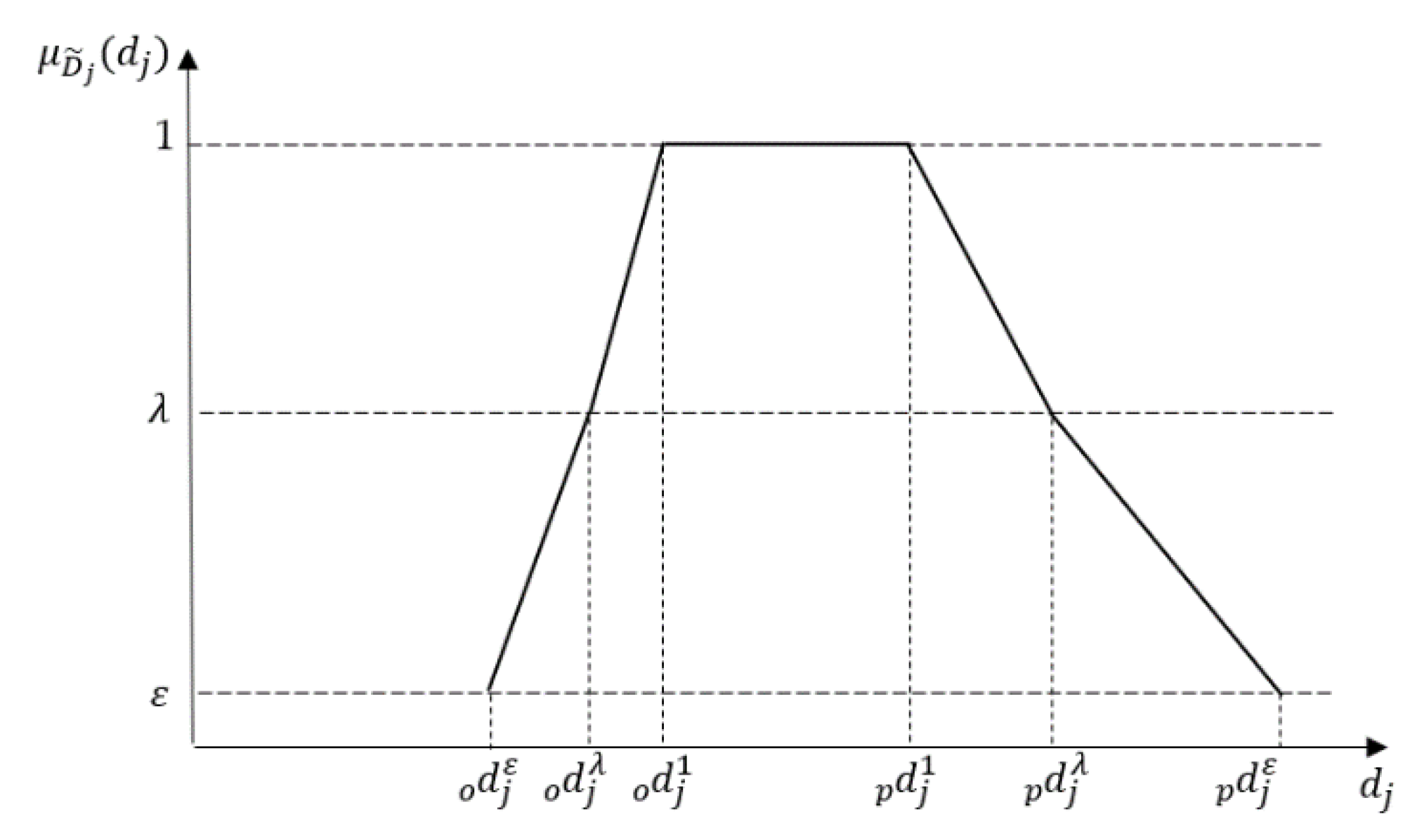
3.2. Disassembling Duration Assessment by Fuzzy Logic
- Determine fuzzy durations for each disassembly step based on the conducted disassembling experiment and expert knowledge to validate the durations.
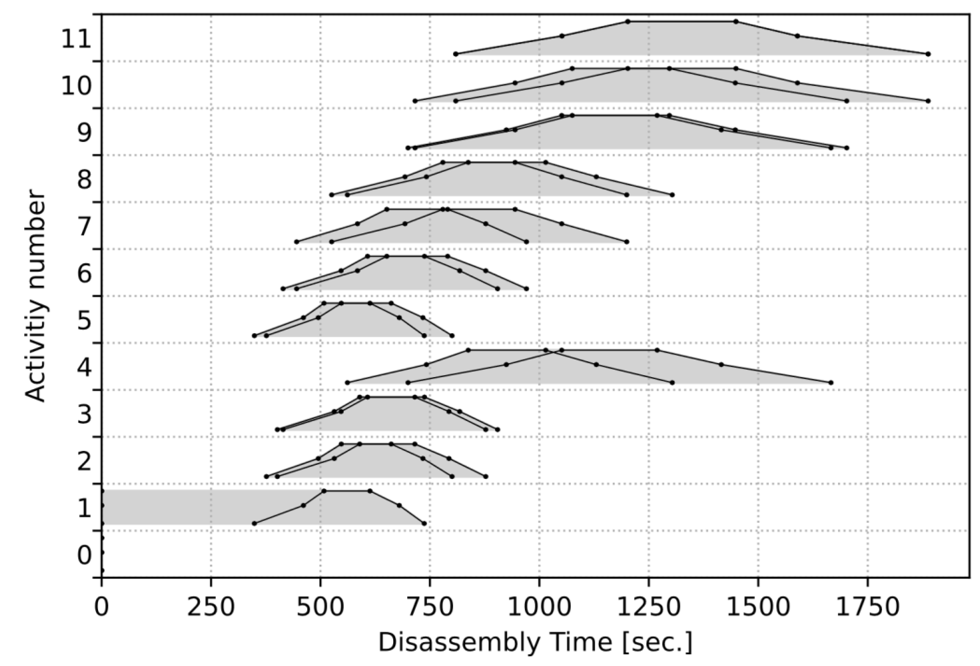
- Conduct the critical path method (CPM), known for scheduling tasks with fuzzy durations to gain a feasible disassembling schedule with minimum total fuzzy disassembling time.
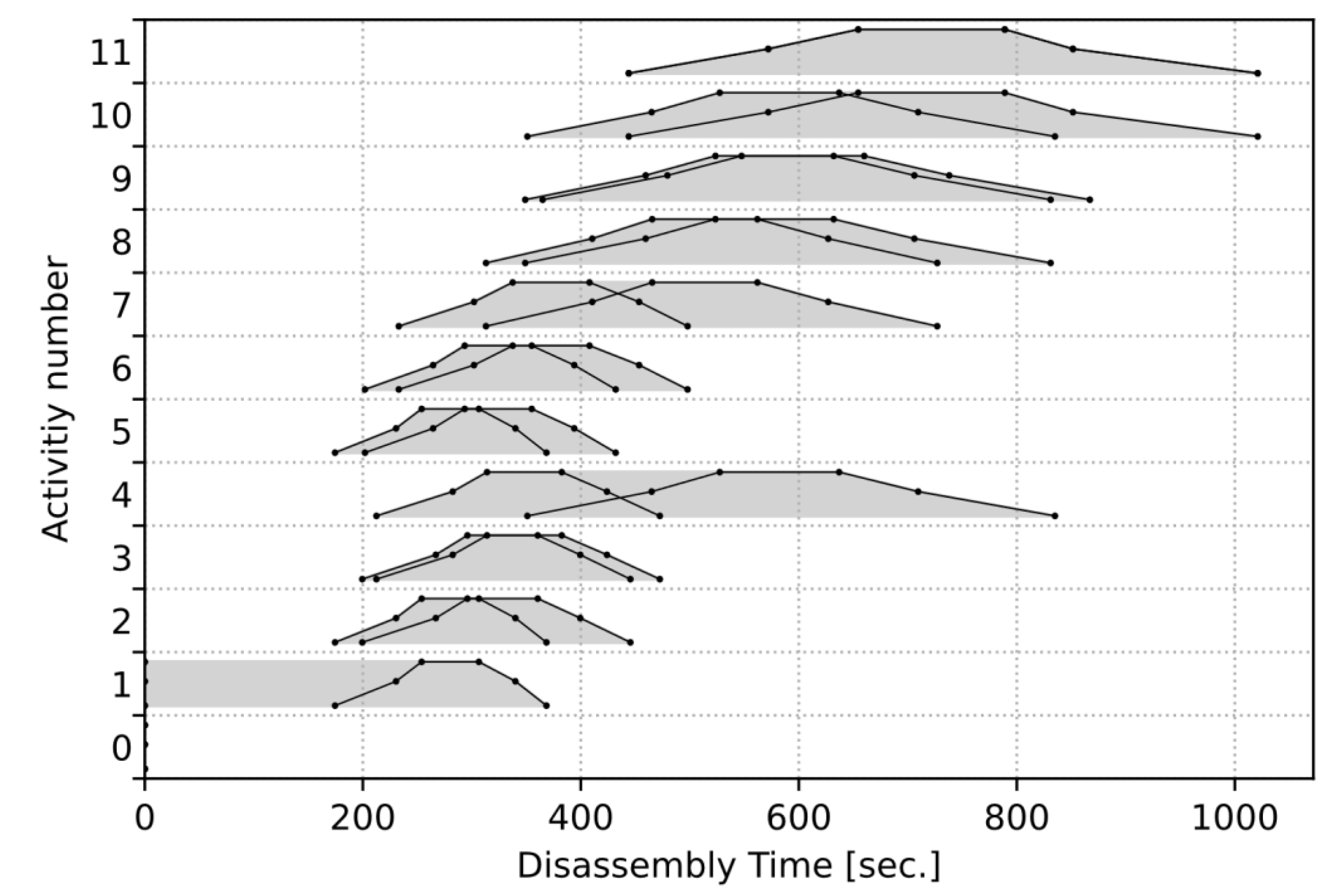
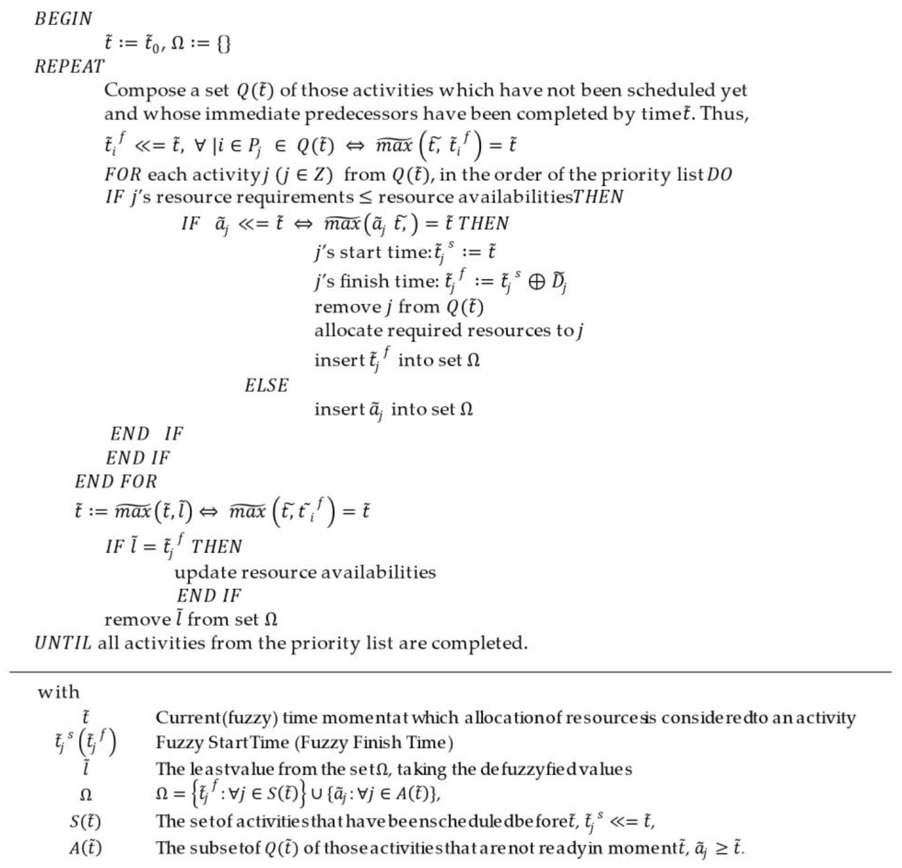
- Apply a heuristic scheduling procedure with resource constraints to calculate the fuzzy and defuzzyfied disassembling times for different workforce settings.
3.3. Cost Estimation
4. Results
4.1. Disassembling Results from Experiment
4.2. Disassembling Duration Assessment by Fuzzy Logic
4.3. Cost Estimation
5. Discussion
5.1. Disassembling Results from Experiment
5.2. Disassembling Duration Assessment by Fuzzy Logic
5.3. Cost Estimation
5.4. View on EVBS Disassembly Automation
- If screws are used, minimize the number of different screw heads to lower the number of needed tool changes.
- Use screws and plug connections instead of adhesives whenever possible or give instructions to best solve adhesive connections (examples: solvent, ultrasound)
- If non-destructive disassembly is the goal, minimize the number of different snap-fit connections.
- Screws should be accessible from a vertical position wherever possible or at least from the same direction for as many screws as possible.
- Supply accessible fixing points to secure the battery system during disassembly.
- Use modular construction that allows disassembly into sub-assemblies.
- Try to minimize the use of different materials in sub-assemblies, which is beneficial for further treatment and separation.
- Have connectors directly accessible whenever possible without having to remove other components.
- Have a fixed cable routing so that a robot will be less likely to get stuck during operation.
- Label the battery system with a unique code to retrieve disassembly instructions (example: QR code).
6. Conclusions and Outlook
Supplementary Materials
Author Contributions
Funding
Data Availability Statement
Acknowledgments
Conflicts of Interest
Nomenclature and Abbreviations
| Abbreviations | Translation |
| BEV | Battery electric vehicle |
| BMC | Battery management controller |
| CPM | Critical path method |
| EoL | End-of-Life |
| EV | Electric vehicle |
| EVB | Electric vehicle battery |
| EVBS | Electric vehicle battery system |
| FTE | Fulltime employee |
| HV | High voltage |
| PHEV | Plug-in hybrid vehicle |
| Symbol | Meaning |
| Several membership levels | |
| Fuzzy set | |
| -level cuts of Interval | |
| Scaled battery module weight | |
| Original battery module weight | |
| Exponential scaling factor | |
| Term for an additional disassembling time change | |
| Fuzzy disassembling duration ofactivity j (six-point representation) | |
| Scaled disassembly duration | |
| Original disassembly duration | |
| Membership level | |
| Fuzzy earliest finish of activity j | |
| Fuzzy earliest start of activity j | |
| Defuzzyfied latest finish time step j | |
| Height of normalized fuzzy set | |
| Membership level | |
| Fuzzy latest finish time of activity j | |
| Membership function [0, 1] | |
| Membership function | |
| Latest completion time of the project | |
| Fuzzy finish time | |
| Fuzzy start time | |
| ⊖ | Subtraction |
| Addition | |
| Inverse addition |
Appendix A
Appendix B
Appendix C

| Description of Included Activities | |
|---|---|
| 1 | 1.1 Screws are removed: (3, 3.5, 4, 5, 5.5, 6) × 40 1.2 Cutting of adhesive is time-consuming and less standardized (variation in duration expected):(220, 300, 320, 380, 420, 450) 1.3 Remove of clamping bar by hand: (1, 1.5, 2, 2, 2.5, 3) ×4 1.4 Lift off upper cover and if necessary recut: (5, 15, 20, 25, 30, 35) |
| 2 | 2.1 Screws identical to upper cover screw, removed with extension, add one second for extension:(4, 4.5, 5, 6, 6.5, 6, 7) × 2 2.2 Remove plugs with a combination of hand and hand screwdriver, variances may occur: (8, 13, 15, 20, 22, 30) × 2 2.3 Remove busbar by hand: (1, 1.5, 2, 2, 2.5, 3) |
| 3 | 3.1 Screws are removed: (3, 3.5, 4, 5, 5.5, 6) × 4 3.2 Remove support strut by hand: (1, 1.5, 2, 2, 2.5, 3) |
| 4 | 4.1 Remove air dryer; snap-on fasteners with latches are difficult to open because pressure points are poorly accessible; therefore, variance is expected: (10, 12, 15, 20, 23, 25) 4.2 Open air dryer; force is needed, or experience; the variance is expected; own disassembling time was longer than expected in most cases: (15, 20, 23, 27, 30, 35) 4.3 Remove plugs from BMC; variance expected; although different plugs, same time per plug in the calculation:(4, 6, 7, 8, 9, 14) × 6 4.4 Remove screw from interference suppression filter: (3, 3.5, 4, 5, 5.5, 6) 4.5 Remove interference suppression filter by hand: (1, 1.5, 2, 2, 2.5, 3) 4.6 Remove screws from air dryer bracket: (3, 3.5, 4, 5, 5.5, 6) × 2 4.7 Remove air dryer bracket by hand: (1, 1.5, 2, 2, 2.5, 3) 4.8 Remove plug from interference suppression filter; pointed pliers is used (time for tool changing). Add 0.5 s per plug: (4.5, 6.5, 7.5, 8.5, 9.5, 14.5) × 5 4.9 Remove further plugs; poorly accessible; time comparable to 4.2: (15, 20, 23, 27, 30, 35) 4.10 Remove screws from interference filter: (3, 3.5, 4, 5, 5.5, 6) × 3 4.11 Remove interference filter holder, took slightly longer than other removal by hand because of position (add 2 s): (3, 3.5, 4, 4, 4.5, 5) 4.12 Remove screws from the BMC: (3, 3.5, 4, 5, 5.5, 6) × 2 4.13 Remove screws from the BMC; outside the battery cover, tool change; add 0.5 s per screw: (3.5, 4, 4.5, 5.5, 6, 6.5) × 4 4.14 Remove BMC by hand: (1, 1.5, 2, 2, 2.5, 3) 4.15 Open BMC, comparable to snap-fastener of air dryer for removal, but two seconds faster:(8, 10, 13, 18, 21, 23) |
| 5 | 5.1 Remove screws from battery sensor with shunt: (3, 3.5, 4, 5, 5.5, 6) × 8 5.2 Remove plug; better accessible than 4.8; 1.5 s less: (2.5, 4.5, 5.5, 6.5, 7.5, 12.5) 5.3 Remove battery sensor with shunt by hand: (1, 1.5, 2, 2, 2.5, 3) |
| 6 | 6.1 Remove screws from busbar 2: (3, 3.5, 4, 5, 5.5, 6) × 2 6.2 Remove busbar 2 by hand: (1, 1.5, 2, 2, 2.5, 3) 6.3 Remove power plugs and cable fixers; plugs and fixers are easily accessible and better accessible than 5.2; time equivalent to screws: (3, 3.5, 4, 5, 5.5, 6) × 5 6.4 Remove screws from busbar 3 with integrated fuse: (3, 3.5, 4, 5, 5.5, 6) × 4 6.5 Remove busbar 3 with integrated fuse: (1, 1.5, 2, 2, 2.5, 3) 6.6 Remove screws on busbar 3; same time assumptions as for other screws, although they have slightly more weight: (3, 3.5, 4, 5, 5.5, 6) × 2 6.7 Remove the fuse from busbar 3 by hand: (1, 1.5, 2, 2, 2.5, 3) |
| 7 | 7.1 Remove plugs from console; comparable to 5.2: (2.5, 4.5, 5.5, 6.5, 7.5, 12.5) × 7 7.2 Remove screws from console: (3, 3.5, 4, 5, 5.5, 6) × 5 7.3 Remove console by hand: (1, 1.5, 2, 2, 2.5, 3) 7.4 Remove plugs from wiring harness and relay; comparable to 7.1/5.2: (2.5, 4.5, 5.5, 6.5, 7.5, 12.5) × 2 7.5 Remove screws and nut from series resistor; add 0.5 to screw time per screw to include change of tool to wrench: (3.5, 4, 4.5, 5.5, 6, 6.5) × 5 7.6 Remove relay by hand: (1, 1.5, 2, 2, 2.5, 3) 7.7 Remove screws from connectors: (3, 3.5, 4, 5, 5.5, 6) × 7 7.8 Remove copper coils by hand: (1, 1.5, 2, 2, 2.5, 3) × 2 |
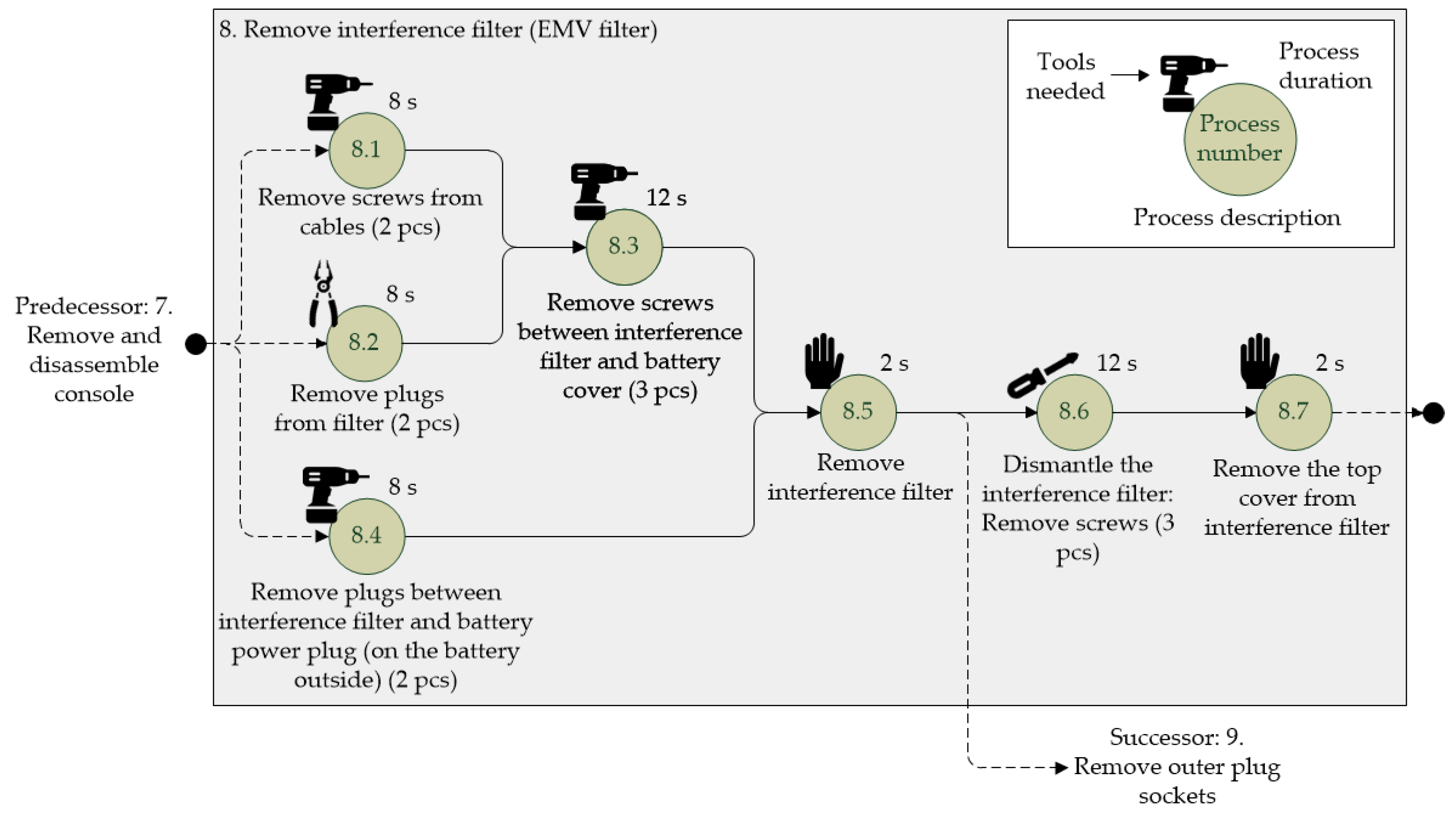
| 8 | 8.1 Remove screws from cables: (3, 3.5, 4, 5, 5.5, 6) × 2 8.2 Remove plugs from filter; comparable to 5.2: (2.5, 4.5, 5.5, 6.5, 7.5, 12.5) × 2 8.3 Remove screws between interference […]; comparable to 5.2: (2.5, 4.5, 5.5, 6.5, 7.5, 12.5) × 2 8.4 Remove screws between interference filter and battery cover: (3, 3.5, 4, 5, 5.5, 6) × 3 8.5 Remove interference filter by hand: (1, 1.5, 2, 2, 2.5, 3) 8.6 Remove screws to dismantle the interference filter: (3, 3.5, 4, 5, 5.5, 6) × 3 8.7 Remove the top cover of the interference filter by hand: (1, 1.5, 2, 2, 2.5, 3) |
| 9 | 9.1 Remove screws from HV connector form the outside of the cover: (3, 3.5, 4, 5, 5.5, 6) × 2 9.2 Remove HV connector by hand: (1, 1.5, 2, 2, 2.5, 3) 9.3 Remove screws inside console from orange component: (3, 3.5, 4, 5, 5.5, 6) × 2 9.4 Remove orange component by hand: (1, 1.5, 2, 2, 2.5, 3) 9.5 Open orange component to retrieve cover by hand: (1, 1.5, 2, 2, 2.5, 3) 9.6 Remove diagnostic connector by hand: (1, 1.5, 2, 2, 2.5, 3) |
| 10 | 10.1 Remove screws that connect modules to lower battery cover; screws are longer than others (add 0.5 s); change of bit set to keep the same tool (add 1 s): (4.5, 5, 5.5, 6.5, 6.5, 7.5) × 8 10.2 Move lifting/pulling device (winch) to work station; assumed that it is provided closely without need to walk: (3, 3.5, 4, 5, 5.5, 6) 10.3 Hook up the corner of the battery module to the lifting device and clamp the lower battery cover to the working station (screw clamps): (17, 20, 25, 30, 35, 37) 10.4 Operate the winch by hand; Reference is a previously conducted experiment with a similar battery type: (17, 20, 25, 30, 35, 37) 10.5 Place battery modules next to lower battery cover and unhook; release clamped lower batter cover): (17, 20, 25, 30, 35, 37) 10.6 Put away lifting/pulling device: (3, 3.5, 4, 5, 5.5, 6) |
| 0 | (0, 0, 0, 0, 0, 0) | |
| 1 | (0, 0, 0, 0, 0, 0) | |
| 2 | (349, 461, 508, 615, 680, 737) | |
| 3 | (374, 497.5, 550, 667, 739.5, 814) | |
| 4 | (387, 513, 568, 689, 764, 841) | |
| 5 | (349, 461, 508, 615, 680, 737) | |
| 6 | (376.5, 495, 547.5, 661.5, 734, 800.5) | |
| 7 | (407.5, 532.5, 591.5, 714.5, 793.5, 866.5) | |
| 8 | (487.5, 641, 719.5, 868.5, 967, 1095.5) | |
| (523.5, 690, 777.5, 938.5, 1046, 1199.5) | ||
| (407.5, 532.5, 591.5, 714.5, 793.5, 866.5) | ||
| 11 | (539.5, 710, 801.5, 966.5, 1078, 1235.5) |
| 0 | (0, 0, 0, 0, 0, 0, 0) | |
| 1 | (349, 461, 508, 615, 680, 737) | |
| 2 | (388, 512, 570, 690, 768, 846) | |
| 3 | (401, 527.5, 588, 712, 792.5, 873) | |
| 4 | (487.5, 641, 719.5, 868.5, 967, 1095.5) | |
| 5 | (376.5, 495, 547.5, 661.5, 734, 800.5) | |
| 6 | (407.5, 532.5, 591.5, 714.5, 793.5, 866.5) | |
| 7 | (487.5, 641, 719.5, 868.5, 967, 1095.5) | |
| 8 | (523.5, 690, 777.5, 935.5, 1046, 1199.5) | |
| (539.5, 710, 801.5, 966.5, 1078, 1235.5) | ||
| (539.5, 710, 801.5, 966.5, 1078, 1235.5) | ||
| 11 | (539.5, 710, 801.5, 966.5, 1078, 1235.5) |
| Planning Order | Fuzzy Start Time [s] | Fuzzy Finish Time [s] | |
|---|---|---|---|
| 1 | 0 | (0, 0, 0, 0, 0, 0, 0) | (0, 0, 0, 0, 0, 0, 0) |
| 2 | 1 | (0, 0, 0, 0, 0, 0, 0) | (349, 461, 508, 615, 680, 737) |
| 3 | 5 | (349, 461, 508, 615, 680, 737) | (376.5, 495, 547.5, 661.5, 734, 800.5) |
| 4 | 2 | (376.5, 495, 547.5, 661.5, 734, 800.5) | (401.5, 531.5, 589.5, 715.5, 793.5, 877.5) |
| 5 | 3 | (401.5, 531.5, 589.5, 715.5, 793.5, 877.5) | (414.5, 547, 607.5, 735.5, 818, 904.5) |
| 6 | 6 | (414.5, 547, 607.5, 735.5, 818, 904.5) | (445.5, 584.5, 651.5, 790.5, 877.5, 970.5) |
| 7 | 7 | (445.5, 584.5, 651.5, 790.5, 877.5, 970.5) | (525.5, 693, 779.5, 944.5, 1051, 1199.5) |
| 8 | 8 | (525.5, 693, 779.5, 944.5, 1051, 1199.5) | (561.5, 742, 837.5, 1014.5, 1130, 1303.5) |
| 9 | 4 | (561.5, 742, 837.5, 1014.5, 1130, 1303.5) | (700, 924.5, 1051, 1269, 1415.5, 1666) |
| 10 | (700, 924.5, 1051, 1269, 1415.5, 1666) | (716, 944.5, 1075, 1297, 1447.5, 1702) | |
| 11 | (716, 944.5, 1075, 1297, 1447.5, 1702) | (809, 1051.5, 1202, 1449, 1589.5, 1888) | |
| 12 | 11 | (809, 1051.5, 1202, 1449, 1589.5, 1888) | (809, 1051.5, 1202, 1449, 1589.5, 1888) |
| Planning Order | Worker One Step | Worker Two Step | Fuzzy Start Time [s] | Fuzzy Finish Time [s] |
|---|---|---|---|---|
| 1 | ||||
| 2 | 1 | (349, 461, 508, 615, 680, 737) | ||
| 3 | 5 | (349, 461, 508, 615, 680, 737) | (376.5, 495, 547.5, 661.5, 734, 800.5) | |
| 3 | 2 | (349, 461, 508, 615, 680, 737) | (374, 497.5, 550, 667, 739.5, 814) | |
| 4 | 6 | (376.5, 495, 547.5, 661.5, 734, 800.5) | (407.5, 532.5, 591.5, 714.5, 793.5, 866.5) | |
| 5 | 3 | (374, 497.5, 550, 667, 739.5, 814) | (387, 513, 568, 689, 764, 841) | |
| 6 | 4 | (387, 513, 568, 689, 764, 841) | (525.5, 695.5, 781.5, 943.5, 1049.5, 1203.5) | |
| 7 | 7 | (407.5, 532.5, 591.5, 714.5, 793.5, 866.5) | (487.5, 641, 719.5, 868.5, 967, 1095.5) | |
| 8 | 8 | (487.5, 641, 719.5, 868.5, 967, 1095.5) | (523.5, 690, 777.5, 938.5, 1046, 1199.5) | |
| 9 | 9 | (523.5, 690, 777.5, 938.5, 1046, 1199.5) | (539.5, 710, 801.5, 966.5, 1078, 1235.5) | |
| 10 | 10 | (525.5, 695.5, 781.5, 943.5, 1049.5, 1203.5) | (618, 802.5, 908.5, 1095.5, 1191.5, 1389.5) | |
| 11 | (618, 802.5, 908.5, 1095.5, 1191.5, 1389.5) | (618, 802.5, 908.5, 1095.5, 1191.5, 1389.5) |
| Planning Order | Worker One Step j | Worker Two Step j | Fuzzy Start Time [s] | Fuzzy Finish Time [s] |
|---|---|---|---|---|
| 1 | ||||
| 2 | 1 | 1 | ||
| 3 | 2 | |||
| 3 | 5 | |||
| 4 | 6 | |||
| 5 | 3 | |||
| 6 | 4 | |||
| 7 | 7 | |||
| 8 | 8 | |||
| 9 | 9 | |||
| 10 | 10 | |||
| 11 |

References
- European Commission. The European Green Deal (COM(2019) 640 Final). 2019. Available online: https://eur-lex.europa.eu/legal-content/EN/TXT/?uri=CELEX%3A52019DC0640&qid=1639045060648 (accessed on 8 December 2021).
- European Commission. A Clean Planet for all: A European Strategic Long-Term Vision for a Prosperous, Modern, Competitive and Climate Neutral Economy (COM(2018) 773 Final). 2018. Available online: https://eur-lex.europa.eu/legal-content/EN/ALL/?uri=COM%3A2018%3A773%3AFIN (accessed on 8 December 2021).
- European Commission. A New Circular Economy Action Plan for a Cleaner and More Competitive Europe (COM(2020) 98 Final). 2020. Available online: https://eur-lex.europa.eu/legal-content/EN/TXT/?qid=1583933814386&uri=COM:2020:98:FIN (accessed on 8 December 2021).
- Pagliaro, M.; Meneguzzo, F. Lithium battery reusing and recycling: A circular economy insight. Heliyon 2019, 5, e01866. [Google Scholar] [CrossRef] [PubMed] [Green Version]
- Glöser-Chahoud, S.; Huster, S.; Rosenberg, S.; Baazouzi, S.; Kiemel, S.; Singh, S.; Schneider, C.; Weeber, M.; Miehe, R.; Schultmann, F. Industrial disassembling as a key enabler of circular economy solutions for obsolete electric vehicle battery systems. Resour. Conserv. Recycl. 2021, 174, 105735. [Google Scholar] [CrossRef]
- Baazouzi, S.; Rist, F.P.; Weeber, M.; Birke, K.P. Optimization of disassembly strategies for electric vehicle batteries. Batteries 2021, 7, 74. [Google Scholar] [CrossRef]
- Baars, J.; Domenech, T.; Bleischwitz, R.; Melin, H.E.; Heidrich, O. Circular economy strategies for electric vehicle batteries reduce reliance on raw materials. Nat. Sustain. 2021, 4, 71–79. [Google Scholar] [CrossRef]
- Moore, E.A.; Russell, J.D.; Babbitt, C.W.; Tomaszewski, B.; Clark, S.S. Spatial modeling of a second-use strategy for electric vehicle batteries to improve disaster resilience and circular economy. Resour. Conserv. Recycl. 2020, 160, 104889. [Google Scholar] [CrossRef]
- Kirchherr, J.; Reike, D.; Hekkert, M. Conceptualizing the circular economy: An analysis of 114 definitions. Resour. Conserv. Recycl. 2017, 127, 221–232. [Google Scholar] [CrossRef]
- Alfaro-Algaba, M.; Ramirez, F.J. Techno-economic and environmental disassembly planning of lithium-ion electric vehicle battery packs for remanufacturing. Resour. Conserv. Recycl. 2020, 154, 104461. [Google Scholar] [CrossRef]
- Windisch-Kern, S.; Gerold, E.; Nigl, T.; Jandric, A.; Altendorfer, M.; Rutrecht, B.; Scherhaufer, S.; Raupenstrauch, H.; Pomberger, R.; Antrekowitsch, H.; et al. Recycling chains for lithium-ion batteries: A critical examination of current challenges, opportunities and process dependencies. Waste Manag. 2022, 138, 125–139. [Google Scholar] [CrossRef]
- Li, L.; Zheng, P.; Yang, T.; Sturges, R.; Ellis, M.W.; Li, Z. Disassembly automation for recycling end-of-life lithium-ion pouch cells. JOM 2019, 71, 4457–4464. [Google Scholar] [CrossRef] [Green Version]
- Marshall, J.; Gastol, D.; Sommerville, R.; Middleton, B.; Goodship, V.; Kendrick, E. Disassembly of Li ion cells—characterization and safety considerations of a recycling scheme. Metals 2020, 10, 773. [Google Scholar] [CrossRef]
- Elwert, T.; Goldmann, D.; Römer, F.; Buchert, M.; Merz, C.; Schueler, D.; Sutter, J. Current developments and challenges in the recycling of key components of (hybrid) electric vehicles. Recycling 2016, 1, 25–60. [Google Scholar] [CrossRef]
- Lisbona, D.; Snee, T. A review of hazards associated with primary lithium and lithium-ion batteries. Process Saf. Environ. Prot. 2011, 89, 434–442. [Google Scholar] [CrossRef]
- Gumanova, V.; Sobotova, L. Proposal for disassembly of electric vehicle batteries used in the volkswagen jetta hybrid system. In Proceedings of the 2019 International Council on Technologies of Environmental Protection (ICTEP), Stary Smokovec, Slovakia, 23–25 October 2019; pp. 100–106. [Google Scholar]
- Wegener, K.; Andrew, S.; Raatz, A.; Dröder, K.; Herrmann, C. Disassembly of electric vehicle batteries using the example of the audi Q5 hybrid system. Procedia CIRP 2014, 23, 155–160. [Google Scholar] [CrossRef] [Green Version]
- Rallo, H.; Benveniste, G.; Gestoso, I.; Amante, B. Economic analysis of the disassembling activities to the reuse of electric vehicles Li-ion batteries. Resour. Conserv. Recycl. 2020, 159, 104785. [Google Scholar] [CrossRef]
- Hellmuth, J.F.; DiFilippo, N.M.; Jouaneh, M.K. Assessment of the automation potential of electric vehicle battery disassembly. J. Manuf. Syst. 2021, 59, 398–412. [Google Scholar] [CrossRef]
- Gerlitz, E.; Greifenstein, M.; Hofmann, J.; Fleischer, J. Analysis of the variety of lithium-ion battery modules and the challenges for an agile automated disassembly system. Procedia CIRP 2021, 96, 175–180. [Google Scholar] [CrossRef]
- Herrmann, C.; Raatz, A.; Mennenga, M.; Schmitt, J.; Andrew, S. Assessment of automation potentials for the disassembly of automotive lithium ion battery systems. In Leveraging Technology for a Sustainable World; Dornfeld, D.A., Linke, B.S., Eds.; Springer: Berlin/Heidelberg, Germany, 2012; pp. 149–154. [Google Scholar]
- Wegener, K.; Chen, W.H.; Dietrich, F.; Dröder, K.; Kara, S. Robot assisted disassembly for the recycling of electric vehicle batteries. Procedia CIRP 2015, 29, 716–721. [Google Scholar] [CrossRef]
- Garrido-Hidalgo, C.; Ramirez, F.J.; Olivares, T.; Roda-Sanchez, L. The adoption of internet of things in a circular supply chain framework for the recovery of WEEE: The case of lithium-ion electric vehicle battery packs. Waste Manag. 2020, 103, 32–44. [Google Scholar] [CrossRef] [PubMed]
- Tan, W.J.; Chin, C.M.M.; Garg, A.; Gao, L. A hybrid disassembly framework for disassembly of electric vehicle batteries. Int. J. Energy Res. 2021, 45, 8073–8082. [Google Scholar] [CrossRef]
- Lander, L.; Cleaver, T.; Rajaeifar, M.A.; Nguyen-Tien, V.; Elliott, R.J.; Heidrich, O.; Kendrick, E.; Edge, J.S.; Offer, G. Financial viability of electric vehicle lithium-ion battery recycling. Iscience 2021, 24, 102787. [Google Scholar] [CrossRef]
- Schultmann, F. Stoffstrombasiertes Produktionsmanagement: Betriebswirtschaftliche Planung und Steuerung Industrieller Kreislaufwirtschaftssysteme; Erich Schmidt: Berlin, Germany, 2003; Volume 58. [Google Scholar]
- Nguyen, H.T.; Walker, E.A.; Walker, E. A First Course in Fuzzy Logic, 2nd ed.; Chapman & Hall/CRC: Boca Raton, FL, USA, 2020. [Google Scholar]
- Liang, J.; Guo, S.; Zhang, Y.; Liu, W.; Zhou, S. Energy-efficient optimization of two-sided disassembly line balance considering parallel operation and uncertain using multiobjective flatworm algorithm. Sustainability 2021, 13, 3358. [Google Scholar] [CrossRef]
- Bentaha, M.L.; Battaïa, O.; Dolgui, A.; Hu, S.J. Dealing with uncertainty in disassembly line design. CIRP Ann. 2014, 63, 21–24. [Google Scholar] [CrossRef]
- Ke, Q.; Zhang, P.; Zhang, L.; Song, S. Electric vehicle battery disassembly sequence planning based on frame-subgroup structure combined with genetic algorithm. Front. Mech. Eng. 2020, 6, 576642. [Google Scholar] [CrossRef]
- Shaocheng, T. Interval number and fuzzy number linear programmings. Fuzzy Sets Syst. 1994, 66, 301–306. [Google Scholar] [CrossRef]
- Hapke, M.; Slowinski, R. Fuzzy priority heuristics for project scheduling. Fuzzy Sets Syst. 1996, 83, 291–299. [Google Scholar] [CrossRef]
- Sadollah, A. Fuzzy Logic Based in Optimization Methods and Control Systems and Its Applications; InTechOpen: London, UK, 2018. [Google Scholar]
- Rommelfanger, H. Fuzzy decision support-systeme: Entscheiden bei Unschärfe. In Springer-Lehrbuch, 2nd ed.; Springer: Berlin/Heidelberg, Germany, 1994. [Google Scholar]
- Radot, A.D.; Rakshit, A. A ‘fuzzy’ approach to facilities lay-out planning. Int. J. Prod. Res. 1991, 29, 835–857. [Google Scholar] [CrossRef]
- Schultmann, F.; Rentz, O. Fuzzy scheduling for the dismantling of complex products. In Operations Research, Proceedings of the 2002: Selected Papers of the International Conference on Operations Research (SOR 2002), Klagenfurt, Austria, 2–5 September 2002; Leopold-Wildburger, U., Ed.; Springer: Berlin/Heidelberg, Germany, 2003; pp. 302–307. [Google Scholar]
- Zadeh, L.A. Fuzzy sets. Inf. Control. 1965, 8, 338–353. [Google Scholar] [CrossRef] [Green Version]
- Schultmann, F.; Fröhling, M.; Rentz, O. Fuzzy approach for production planning and detailed scheduling in paints manufacturing. Int. J. Prod. Res. 2006, 44, 1589–1612. [Google Scholar] [CrossRef]
- Bhunia, A.K.; Sahoo, L.; Shaikh, A.A. Project management. In Advanced Optimization and Operations Research; Bhunia, A.K., Sahoo, L., Shaikh, A.A., Eds.; Springer: Singapore, 2019; Volume 153, pp. 367–402. [Google Scholar]
- Hapke, M.; Jaszkiewicz, A.; Słowiński, R. Fuzzy multi-mode resource-constrained project scheduling with multiple objectives. In Project Scheduling; Hillier, F.S., Węglarz, J., Eds.; Springer: Boston, MA, USA, 1999; Volume 14, pp. 353–380. [Google Scholar]
- Wang, K. Computational intelligence in agile manufacturing engineering. In Agile Manufacturing: The 21st Century Competitive Strategy; Gunasekaran, A., Ed.; Elsevier: Amsterdam, The Netherlands, 2001; pp. 297–315. [Google Scholar]
- Cho, J.-H.; Kim, Y.-D. A simulated annealing algorithm for resource constrained project scheduling problems. J. Oper. Res. Soc. 1997, 48, 736–744. [Google Scholar] [CrossRef]
- Hapke, M.; Jaszkiewicz, A.; Slowinski, R. Fuzzy project scheduling system for software development. Fuzzy Sets Syst. 1994, 67, 101–117. [Google Scholar] [CrossRef]
- Hapke, M.; Słowiński, R. Fuzzy set approach to multi-objective and multi-mode project scheduling under uncertainty. In Scheduling under fuzziness: With 29 Tables; Słowiński, R., Ed.; Physica-Verlag: Heidelberg, Germamy, 2000; pp. 197–221. [Google Scholar]
- Kwade, A.; Bärwaldt, G. Recycling von Lithium-Ionen-Batterien im Rahmen des FuE-Programms. Förderung von Forschung und Entwicklung im Bereich der Elektromobilität. Abschlussbericht, Braunschweig, Germany. 2012. Available online: https://www.erneuerbar-mobil.de/sites/default/files/publications/abschlussbericht-lithorec.pdf (accessed on 26 November 2021).
- Thies, C.; Kieckhäfer, K.; Hoyer, C.; Spengler, T.S. Economic assessment of the lithorec process. In Recycling of Lithium-Ion Batteries: The LithoRec Way; Kwade, A., Diekmann, J., Eds.; Springer: Cham, Switzerland, 2018. [Google Scholar]
- Dai, Q.; Spangenberger, J.; Ahmed, S.; Gaines, L.; Kelly, J.C.; Wang, M. EverBatt: A Closed-Loop Battery Recycling Cost and Environmental Impacts Model; Argonne National Lab.(ANL): Argonne, IL, USA, 2019. [Google Scholar] [CrossRef]
- Lambert, A.J.D.; Gupta, S.M. Disassembly modeling for assembly, maintenance, reuse, and recycling. In The St. Lucie Press Series on Resource Management; CRC Press: Boca Raton, FL, USA, 2005. [Google Scholar]
- Vanegas Pena, P.; Peeters, J.; Cattrysse, D.; Duflou, J.; Tecchio, P.; Mathieux, F.; Ardente, F. Study for a Method to Assess the Ease of Disassembly of Electrical and Electronic Equipment: Method Development and Application to a Flat Panel Display Case Study; Publications Office of the European Union: Luxembourg, 2016. [Google Scholar]
- Asiedu, Y.; Gu, P. Product life cycle cost analysis: State of the art review. Int. J. Prod. Res. 1998, 36, 883–908. [Google Scholar] [CrossRef]
- Kroll, E. Application of work-measurement analysis to product disassembly for recycling. Concurr. Eng. 1996, 4, 149–158. [Google Scholar] [CrossRef]
- Mandolini, M.; Favi, C.; Germani, M.; Marconi, M. Time-based disassembly method: How to assess the best disassembly sequence and time of target components in complex products. Int. J. Adv. Manuf. Technol. 2018, 95, 409–430. [Google Scholar] [CrossRef]
- Desai, A.; Mital, A. Evaluation of disassemblability to enable design for disassembly in mass production. Int. J. Ind. Ergon. 2003, 32, 265–281. [Google Scholar] [CrossRef]
- Vanegas, P.; Peeters, J.R.; Cattrysse, D.; Tecchio, P.; Ardente, F.; Mathieux, F.; Dewulf, W.; Duflou, J.R. Ease of disassembly of products to support circular economy strategies. Resour. Conserv. Recycl. 2018, 135, 323–334. [Google Scholar] [CrossRef] [PubMed]
- Boks, C.B.; Kroll, E.; Brouwers, W.; Stevels, A. Disassembly modeling: Two applications to a Philips 21" television set. In Proceedings of the 1996 IEEE International Symposium on Electronics and the Environment. ISEE-1996, Dallas, TX, USA, 6–8 May 1996; pp. 224–229. [Google Scholar]
- McGlothlin, S.; Kroll, E. Systematic estimation of disassembly difficulties: Application to computer monitors. In Proceedings of the 1995 IEEE International Symposium on Electronics and the Environment ISEE (Cat. No.95CH35718), Orlando, FL, USA, 1–3 May 1995; pp. 83–88. [Google Scholar]
- Favi, C.; Marconi, M.; Germani, M.; Mandolini, M. A design for disassembly tool oriented to mechatronic product de-manufacturing and recycling. Adv. Eng. Inform. 2019, 39, 62–79. [Google Scholar] [CrossRef]
- Kroll, E.; Carver, B.S. Disassembly analysis through time estimation and other metrics. Robot. Comput. Integr. Manuf. 1999, 15, 191–200. [Google Scholar] [CrossRef]
- Das, S.K.; Yedlarajiah, P.; Narendra, R. An approach for estimating the end-of-life product disassembly effort and cost. Int. J. Prod. Res. 2000, 38, 657–673. [Google Scholar] [CrossRef]
- Recchioni, M.; Ardente, F. Environmental Footprint and Material Efficiency Support for Product Policy: Feasibility Study for a Standardised Method to Measure the Time Taken to Extract Certain Parts from Electrical and Electronic Equipment (JRC84311); Publications Office of the European Union: Luxembourg, 2016; Available online: https://op.europa.eu/s/nxGV (accessed on 15 May 2022).
- Fulvio, A.; Fabrice, M.; Marco, R. Recycling of electronic displays: Analysis of pre-processing and potential ecodesign improvements. Resour. Conserv. Recycl. 2014, 92, 158–171. [Google Scholar] [CrossRef]
- Salhofer, S.; Spitzbart, M.; Maurer, K. Recycling of LCD screens in europe-state of the art and challenges. In Glocalized Solutions for Sustainability in Manufacturing, Proceedings of the 18th CIRP International Conference on Life Cycle Engineering, Technische Universität Braunschweig, Braunschweig, Germany, 2–4 May 2011; Hesselbach, J., Ed.; Springer: Berlin/Heidelberg, Germany, 2011. [Google Scholar]
- IEA. Global EV Outlook 2020: Entering the Decade of Electric Drive? 2020. Available online: https://www.iea.org/reports/global-ev-outlook-2020#the-global-electric-vehicle-fleet-expanded-significantly-over-the-last-decade-underpinned-by-supportive-policies-and-technology-advances (accessed on 9 May 2022).
- Malmborg, C.J. Facility design: The block layout planning process for manufacturing systems. In Handbook of Design, Manufacturing and Automation; Dorf, R.C., Kusiak, A., Eds.; John Wiley & Sons, Inc.: Hoboken, NJ, USA, 1994; pp. 461–479. [Google Scholar]
- Sawanishi, H.; Torihara, K.; Mishima, N. A study on disassemblability and feasibility of component reuse of mobile phones. Procedia CIRP 2015, 26, 740–745. [Google Scholar] [CrossRef] [Green Version]
- Stevels, A. Applied EcoDesign Take Back & Recycling. Available online: https://slidetodoc.com/applied-eco-design-take-back-recycling-prof-dr/ (accessed on 2 May 2022).
- Sodhi, R.; Sonnenberg, M.; Das, S. Evaluating the unfastening effort in design for disassembly and serviceability. J. Eng. Des. 2004, 15, 69–90. [Google Scholar] [CrossRef]
- Liu, S.; Yung, K.L.; Ip, W.H. Genetic local search for resource-constrained project scheduling under uncertainty. Int. J. Inf. Manag. Sci. 2007, 347–363. [Google Scholar]
- Sanguesa, J.A.; Torres-Sanz, V.; Garrido, P.; Martinez, F.J.; Marquez-Barja, J.M. A review on electric vehicles: Technologies and challenges. Smart Cities 2021, 4, 22. [Google Scholar] [CrossRef]
- Kondo, Y.; Deguchi, K.; Hayashi, Y.; Obata, F. Reversibility and disassembly time of part connection. Resour. Conserv. Recycl. 2003, 38, 175–184. [Google Scholar] [CrossRef]
- Eucar. Battery Requirements for Future Automotive Applications. 2019. Available online: https://eucar.be/wp-content/uploads/2019/08/20190710-EG-BEV-FCEV-Battery-requirements-FINAL.pdf (accessed on 31 March 2022).
- Prochazka, P.; Cervinka, D.; Martis, J.; Cipin, R.; Vorel, P. Li-ion battery deep discharge degradation. ECS Trans. 2016, 74, 31–36. [Google Scholar] [CrossRef]
- Kampker, A.; Wessel, S.; Fiedler, F.; Maltoni, F. Battery pack remanufacturing process up to cell level with sorting and repurposing of battery cells. J. Remanuf. 2021, 11, 1–23. [Google Scholar] [CrossRef]
- Bhowmick, S. Tesla Model S Battery System: An Engineer’s Perspective. 2021. Available online: https://circuitdigest.com/article/tesla-model-s-battery-system-an-engineers-perspective (accessed on 9 May 2022).
- Volkswagen, A.G. Long Range and Rapid Charging: The Battery System Is at the Heart of the VOLKSWAGEN ID.3, ID.4 and ID.4 GTX. 2021. Available online: https://www.volkswagenag.com/en/news/2021/05/long-range-and-rapid-charging.html# (accessed on 9 May 2022).
- Das, A.; Li, D.; Williams, D.; Greenwood, D. Joining technologies for automotive battery systems manufacturing. World Electr. Veh. J. 2018, 9, 22. [Google Scholar] [CrossRef] [Green Version]
- Arnberger, A.; Coskun, E.; Rutrecht, B. Recycling von lithium-ionen batterien. In Recycling und Rohstoffe; Thiel, S., Thomé-Kozmiensky, E., Goldmann, D., Eds.; Thomé-Kozmiensky Verlag GmbH: Neuruppin, Germany, 2018; pp. 584–599. [Google Scholar]
- Schwarz, T.E.; Rübenbauer, W.; Rutrecht, B.; Pomberger, R. Forecasting real disassembly time of industrial batteries based on virtual MTM-UAS data. Procedia CIRP 2018, 69, 927–931. [Google Scholar] [CrossRef]
- Rohr, S.; Wagner, S.; Baumann, M.; Müller, S.; Lienkamp, M. A techno-economic analysis of end of life value chains for lithium-ion batteries from electric vehicles. In Proceedings of the 2017 Twelfth International Conference on Ecological Vehicles and Renewable Energies (EVER), Monte-Carlo, Monaco, 11–13 April 2017; pp. 1–14. [Google Scholar]
- Hartmann, S.; Briskorn, D. An updated survey of variants and extensions of the resource-constrained project scheduling problem. Eur. J. Oper. Res. 2022, 297, 1–14. [Google Scholar] [CrossRef]
- Herroelen, W.; Leus, R. Project scheduling under uncertainty: Survey and research potentials. Eur. J. Oper. Res. 2005, 165, 289–306. [Google Scholar] [CrossRef] [Green Version]
- Slama, I.; Ben-Ammar, O.; Masmoudi, F.; Dolgui, A. Disassembly scheduling problem: Literature review and future research directions. IFAC-Pap. OnLine 2019, 52, 601–606. [Google Scholar] [CrossRef]
- Wang, H.; Peng QZhang, J.; Gu, P. Selective disassembly planning for the end-of-life product. Procedia CIRP 2017, 60, 512–517. [Google Scholar] [CrossRef]
- Glocalized Solutions for Sustainability in Manufacturing. Proceedings of the 18th CIRP International Conference on Life Cycle Engineering, Technische Universität Braunschweig, Braunschweig, Germany, 2–4 May 2011; Hesselbach, J. (Ed.) Springer: Berlin/Heidelberg, Germany, 2011. [Google Scholar]
- Hjorth, S.; Chrysostomou, D. Human–robot collaboration in industrial environments: A literature review on non-destructive disassembly. Robot. Comput.-Integr. Manuf. 2022, 73, 102208. [Google Scholar] [CrossRef]
- Arbeitsschutzausschüsse beim BMAS. Technische Regel für Arbeitsstätten-Pausen- und Bereitschaftsräume: ASR A4.2. 2022. Available online: https://www.baua.de/DE/Angebote/Rechtstexte-und-Technische-Regeln/Regelwerk/ASR/ASR-A4-2.html (accessed on 15 May 2022).
- Arbeitsschutzausschüsse beim BMAS. Technische Regel für Arbeitsstätten-Raumabmessungen und Bewegungsflächen: ASR A1.2. 2022. Available online: https://www.baua.de/DE/Angebote/Rechtstexte-und-Technische-Regeln/Regelwerk/ASR/ASR-A1-2.html (accessed on 15 May 2022).
- Arbeitsschutzausschüsse beim BMAS. Technische Regel für Arbeitsstätten-Sanitärräume: ASR A4.1. 2022. Available online: https://www.baua.de/DE/Angebote/Rechtstexte-und-Technische-Regeln/Regelwerk/ASR/ASR-A4-1.html (accessed on 15 May 2022).
- Arbeitsschutzausschüsse beim BMAS. Technische Regel für Arbeitsstätten-Verkehrswege: ASR A1.8. 2022. Available online: https://www.baua.de/DE/Angebote/Rechtstexte-und-Technische-Regeln/Regelwerk/ASR/ASR-A1-8.html (accessed on 15 May 2022).
- Deutsche Fassung EN 15221-6:2011; Facility Management-Teil 6: Flächenbemessung im Facility Management. Beuth Verlag GmbH: Berlin, Germany, 2011.
- DIN 277; Grundflächen und Rauminhalte im Hochbau. Beuth Verlag GmbH: Berlin, Germany, 2021.
- Buckley, J.J.; Eslami, E. An introduction to fuzzy logic and fuzzy sets: With 14 tables. In Advances in Soft Computing; Physica-Verlag: Heidelberg, Germany, 2002. [Google Scholar]
- Zadeh, L.A. Fuzzy logic. Computer 1988, 21, 83–93. [Google Scholar] [CrossRef]
- Zhang, H.-C.; Huang, S.H. A fuzzy approach to process plan selection. Int. J. Prod. Res. 1994, 32, 1265–1279. [Google Scholar] [CrossRef]
- Lai, Y.-J. Fuzzy mathematical programming: Methods and applications. In Springer eBook Collection; Springer: Berlin/Heidelberg, Germany, 1992; Volume 394. [Google Scholar]
- Santo Pedro, F.; Carvalho de Barros, L.; Takata Gomes, L. A Survey on Fuzzy Differences. In Proceedings of the 2015 Conference of the International Fuzzy Systems Association and the European Society for Fuzzy Logic and Technology, Gijón, Spain, 30 June–3 July 2015; Atlantis Press: Paris, France, 2015. [Google Scholar]
- Zand, M.; Nasab, M.A.; Hatami, A.; Kargar, M.; Chamorro, H.R. Using adaptive fuzzy logic for intelligent energy management in hybrid vehicles. In Proceedings of the 2020 28th Iranian Conference on Electrical Engineering (ICEE), Tabriz, Iran, 4–6 August 2020; pp. 1–7. [Google Scholar]
- Cetin, M.S.; Guler, H.; Gencoglu, M.T. Fuzzy logic based battery control system design for electric vehicles. In Proceedings of the 2021 Innovations in Intelligent Systems and Applications Conference (ASYU), Elazig, Turkey, 6–8 October 2021; pp. 1–4. [Google Scholar]
- Pamucar, D.; Ebadi Torkayesh, A.; Deveci, M.; Simic, V. Recovery center selection for end-of-life automotive lithium-ion batteries using an integrated fuzzy WASPAS approach. Expert Syst. Appl. 2022, 206, 117827. [Google Scholar] [CrossRef]


| Source | Year | Vehicle/ Battery | Product Information | Disassembly Output | Disassembly Duration/Time | Disassembling Cost |
|---|---|---|---|---|---|---|
| [17] | 2014 | Audi Q5 Hybrid | Components | Priority Matrix; Disassembly graph process steps | ||
| [16] | 2019 | VW Jetta Hybrid | Components | Priority Matrix; Disassembly graph process steps | ||
| [10] | 2020 | Audi A3 Sportback e-tron Hybrid | Components and fasteners (quantities) | Disassembly graph process steps Disassembly Level | Costs are included in a simulation model; not given, e.g., based on disassembly time | |
| [18] | 2020 | Smart EQ Forfour | Time in minutes for conducting process steps, e.g., cover removal | Costs for disassembly to module and cell level 1 (only direct labor) | ||
| [19] | 2021 | 2017 Chevy Bolt | Components and fasteners incl. specification; partly with weights and sizes | Disassembly graph incl. component specification | ||
| This Paper | 2022 | PHEV 2018 midsize/large vehicle | Components and fasteners with information on quantities, screw types, sizes, material, etc. | Disassembly graph on component/component group level; Disassembly graph on detailed activity level 2 | Measured disassembling durations for each activity 2 Fuzzy Logic Approach to include uncertainty about real disassembling time for battery system and steps | Cost estimation for disassembly to module level
|
| Symbol | Arithmetic Operation in Six-Point Representation |
|---|---|
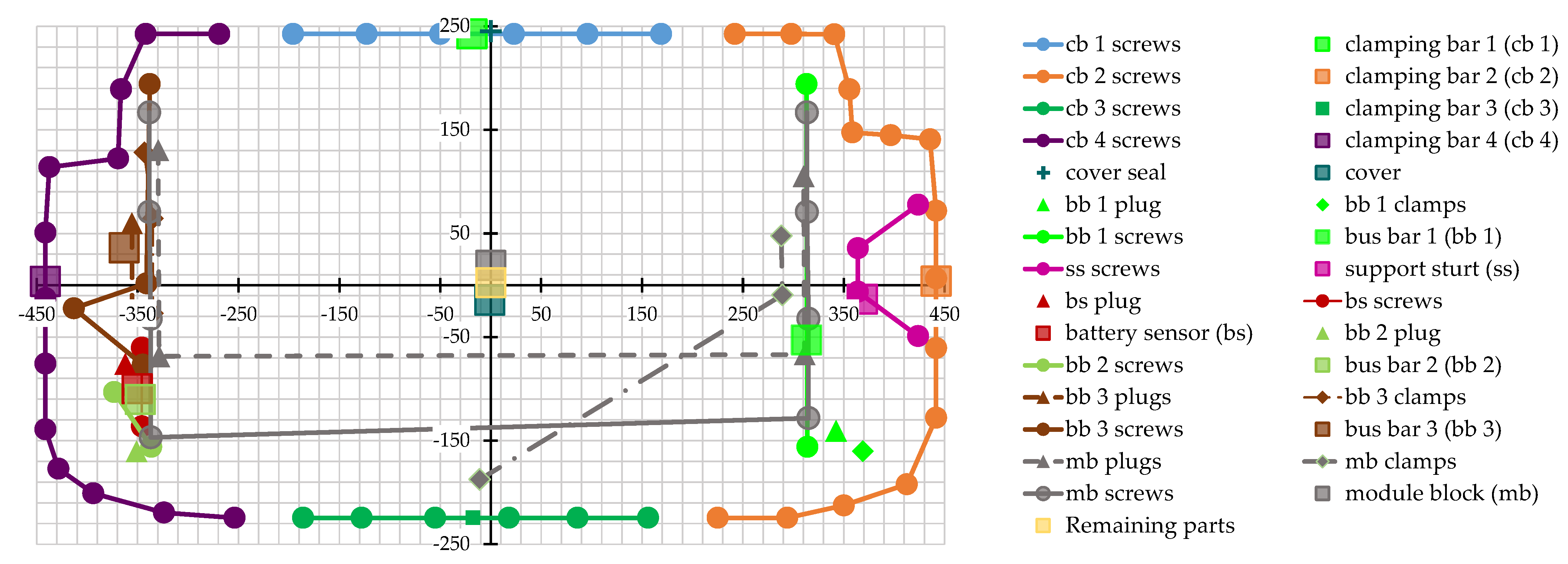
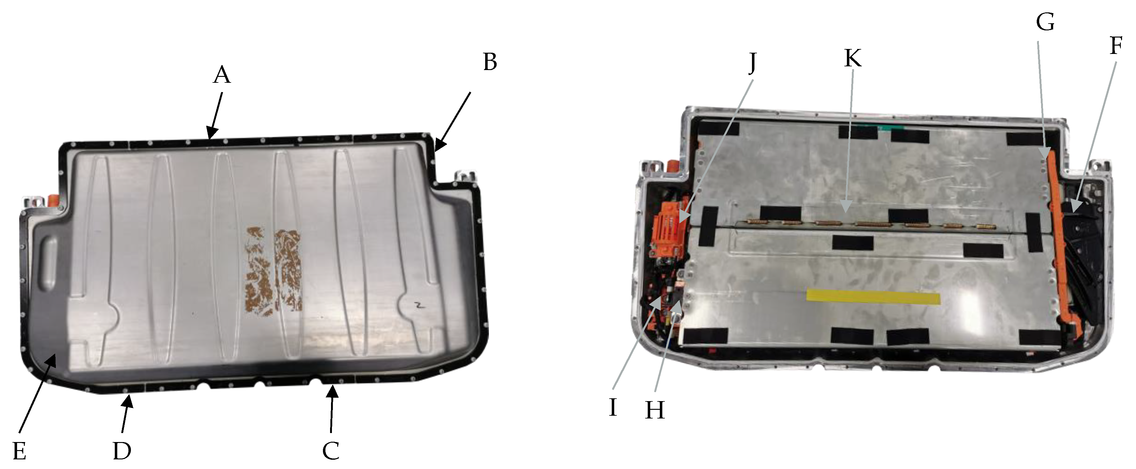
| Parts | ID | Connections |
|---|---|---|
| Clamping bar 1 | A | 6 screws |
| Clamping bar 2 | B | 15 screws |
| Clamping bar 3 | C | 6 screws |
| Clamping bar 4 | D | 13 screws |
| Cover | E | 1 glue |
| Bus bar 1 | F | 2 screws |
| 1 plug | ||
| 2 clamps | ||
| Support strut | G | 4 screws |
| Battery sensor | H | 2 screws |
| 1 plug | ||
| Bus bar 2 | I | 2 screws |
| 1 plug | ||
| Bus bar 3 with integrated fuse | J | 4 screws |
| 2 plugs | ||
| 3 clamps | ||
| Module block | K | 8 screws |
| 4 plugs | ||
| 4 clamps | ||
| Remaining parts | - | - |
| Main Components | Measures [mm] | Weight [g] | Materials |
|---|---|---|---|
| Upper cover | 900 × 480 × 100 | 3690 | Steel |
| Housing base | 898 × 480 × 180 | unknown | Steel |
| Busbars (3) | 380 × 20 × 15 | 256 + 66 + 217 | Metal core, coated with plastic |
| Support strut | 230 × 150 × 20 | 1252.5 | Steel |
| Air dryer | 225 × 14 × 27 | 594 | Plastic and silicate |
| Interference suppression filter | 135 × 60 × 20 | 153 | Plastic and cables |
| BMC | 190 × 105 × 25 | 343 | Plastic housing, circuit board |
| Battery sensor | 95 × 45 × 15 | 47 | Steel, copper, plastic |
| Fuse | 92 × 31 × 31 | 138 | Metal |
| Console | 140 × 110 × 60 | 1284 | Mixed |
| Interference filter | 120 × 73 × 107 | 882 | Mixed |
| Outer plugs | 43 × 45 × 43 (excluding cables) | 59 | Plastic and cables |
| 50 × 65 × 35 | 141 | Steel | |
| Modules | 610 × 398 × 185 | 136,000 | Mixed |
| Rest | - | approx. 2700 (1300 for screws, nuts, and clamping bars) | Mixed |
| Description | ||
|---|---|---|
| Start | (0, 0, 0, 0, 0, 0) | |
| 1 | Remove upper cover | (349, 461, 508, 615, 680, 737) |
| 2 | Remove bus bar 1 | (25, 36.5, 42, 54.5, 59.5, 77) |
| 3 | Remove support strut | (13, 15.5, 18, 22.5, 24.5, 27) |
| 4 | Remove air dryer etc. | (138.5, 182.5, 213.5, 254.5, 285.5, 365.5) |
| 5 | Remove battery sensor | (27.5, 34, 39.5, 48.5, 54, 63.5) |
| 6 | Remove bus bar 2+3 and integrated fuse | (31, 37.5, 44, 53, 59.5, 66) |
| 7 | Remove and disassemble console | (80, 108.5, 128, 154, 173.5, 229) |
| 8 | Remove interference filter | (36, 49, 58, 70, 79, 104) |
| 9 | Remove outer plug sockets | (16, 20, 24, 28, 32, 36) |
| 10 | Remove modules | (93, 107, 127, 152, 142, 186) |
| 11 | End | (0, 0, 0, 0, 0, 0) |
| Defuzzyfied Latest Finish Time | Priority Number Based on
(1: Highest Priority) | |
|---|---|---|
| 0 | 1 | |
| 1 | 560.64 | 2 |
| 2 | 631.39 | 4 |
| 3 | 631.39 | 5 |
| 4 | 889.97 | 8 |
| 5 | 605.06 | 3 |
| 6 | 653.56 | 6 |
| 7 | 798.31 | 7 |
| 8 | 889.97 | 9 * |
| 889.97 | 10 * | |
| 889.97 | 11 * | |
| 889.97 | 12 * |
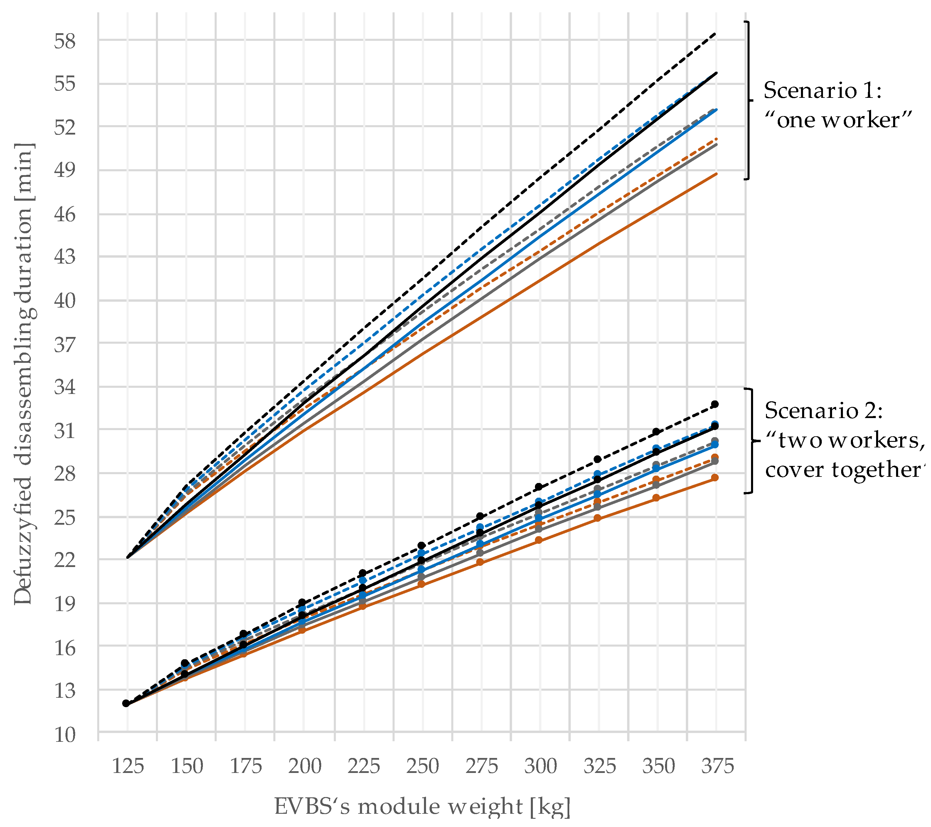
| Scenario Name | Defuzzyfied Disassembling Completion Time [min] | Reduction in % | |
|---|---|---|---|
| Conducted | Alternative | ||
| One worker | 22.2 | 18 | 19 |
| Two workers | 16.7 | 15 | 11.3 |
| Two workers, cover together | 12 | 10.3 | 16.5 |
| Description of Step | Proportionality | Beta Value (for Equation (15)) | |
|---|---|---|---|
| 1 | Remove upper cover | [0.6; 0,7; 0,8; 0.9] | |
| 2 | Remove bus bar 1 | 1 | |
| 3 | Remove support strut | 1 | |
| 4 | Remove air dryer etc. | 0.7 | |
| 5 | Remove battery sensor | 0.7 | |
| 6 | Remove bus bar 2 + 3 and integrated fuse | 1 | |
| 7 | Remove and disassemble console | 0.7 | |
| 8 | Remove interference filter | 0.7 | |
| Remove outer plug sockets | 0 | ||
| Remove modules | 1 |
Publisher’s Note: MDPI stays neutral with regard to jurisdictional claims in published maps and institutional affiliations. |
© 2022 by the authors. Licensee MDPI, Basel, Switzerland. This article is an open access article distributed under the terms and conditions of the Creative Commons Attribution (CC BY) license (https://creativecommons.org/licenses/by/4.0/).
Share and Cite
Rosenberg, S.; Huster, S.; Baazouzi, S.; Glöser-Chahoud, S.; Al Assadi, A.; Schultmann, F. Field Study and Multimethod Analysis of an EV Battery System Disassembly. Energies 2022, 15, 5324. https://doi.org/10.3390/en15155324
Rosenberg S, Huster S, Baazouzi S, Glöser-Chahoud S, Al Assadi A, Schultmann F. Field Study and Multimethod Analysis of an EV Battery System Disassembly. Energies. 2022; 15(15):5324. https://doi.org/10.3390/en15155324
Chicago/Turabian StyleRosenberg, Sonja, Sandra Huster, Sabri Baazouzi, Simon Glöser-Chahoud, Anwar Al Assadi, and Frank Schultmann. 2022. "Field Study and Multimethod Analysis of an EV Battery System Disassembly" Energies 15, no. 15: 5324. https://doi.org/10.3390/en15155324
APA StyleRosenberg, S., Huster, S., Baazouzi, S., Glöser-Chahoud, S., Al Assadi, A., & Schultmann, F. (2022). Field Study and Multimethod Analysis of an EV Battery System Disassembly. Energies, 15(15), 5324. https://doi.org/10.3390/en15155324