Review

Review of Recent Development in Copper/Carbon Composites Prepared by Infiltration Technique

by
Selim Burak Cantürk
1,2,* and
Jaroslav Kováčik
1,*
1
Institute of Materials and Machine Mechanics, Slovak Academy of Sciences, Dúbravská cesta 9, 845 13 Bratislava, Slovakia
2
Faculty of Mechanical Engineering, Slovak University of Technology, Námestie slobody 17, 812 31 Bratislava, Slovakia
*
Authors to whom correspondence should be addressed.
Energies 2022, 15(14), 5227; https://doi.org/10.3390/en15145227
Submission received: 16 June 2022 / Revised: 8 July 2022 / Accepted: 14 July 2022 / Published: 19 July 2022

Abstract

:
The liquid metal infiltration of carbon preformed with copper and its alloys is already an established and well-known process. It is extensively used by the electronic industry to produce heat sinks of power electronics and electric contacts and sliding electric contacts. The advantage of the process is its ability to produce near net shape components with high volume fractions of carbon at a relatively low price. The process is carried out in a vacuum and with low applied pressure. However, a strong dependence on the temperature of infiltration and its precise control is significant for the sound final product. For certain pair carbon matrix–copper alloys, different results could be obtained according to the infiltration temperature. If the temperature is too low, the solidification may occur prior to complete infiltration (high final porosity). When the temperature is too high, undesirable reactions may occur at the fiber–matrix interface (e.g., corrosive carbides). Therefore, there are still a lot of scientific papers pushing this technology to new directions and over old limits. Publications inside scientific journals within this field deal with composite materials for sliding electrical contact and electrical contact materials, sealing materials, parts of brake disks, pantograph strips for high-speed railways, other electric and mechanical applications and even for wall surface shields in future fusion devices. The present paper reviews used carbon preforms, copper alloys, technological parameters, properties of prepared composites prepared via infiltration during the last 12 years. It can be stated that 1/3 of the papers were published within the last 3 years. Moreover, renewed interest in this low-cost technique could be expected within the next few years due to climate programs and increasing prices of the energy resources.

1. Introduction

Climate issues have been a growing concern for humanity over the past 50 years. To tackle issues such as environmental pollution and climate change, it is critical to find out new solutions or redesign old ones. Another concern is caused by the limited raw materials and fossil energy sources with their increasing demand due to increasing number of humans on Earth.
Within this frame, studies that are concerned with decreasing the use of fossil sources and offering redesigned cheap and energy-friendly old production solutions to the mentioned problems are welcome.
Today, carbon is the most widely used reinforcement element in composite material production with its low density, high specific strength and high impact resistance properties. Over the years, a range of processing methods have been developed in an effort to improve the structure and properties of the Cu/carbon type composites. Achieving a homogeneous distribution of alloy in the matrix, forming a strong interfacial bond, and maintaining the carbon’s structural stability are always the most difficult tasks, regardless of the method used. Besides metal infiltration [1,2], other processing techniques that have been used include powder metallurgy [3,4], electrochemical deposition [5,6], CVD [7,8], cold spraying [9], layer-by-layer assembly [10,11], preform impregnation [12], and accumulative roll bonding [13], among others.
When it comes to creating intricate structures, liquid infiltration is by far the most versatile and cheap method. Two main steps are (i) preparation of the preform, which is typically achieved through pressing finely divided material into a mould; (ii) liquid penetration of molten metal into the preform.
Infiltration composite materials are made up of a porous frame made of material with a higher melting point that is surrounded by a low melting point material. When the frame is dipped into a melt of an infiltration material (dipping infiltration), the infiltration material and the porous substrate are heated together above the melting temperature of the infiltration material and after the infiltration, the material and the porous substrate are then removed from the frame. Most typically, the component with a high melting point is tungsten, molybdenum, or tungsten carbide, that is then generally infiltrated with silver, copper or lead. High-loading contact materials are typical applications for tungsten-copper infiltration materials, as well as tungsten-silver and tungsten carbide silver infiltration materials [14,15]. Composites such as molybdenum-copper (MoCu) are also employed as heat sinks for electronic components.
In this method, if the moulds are appropriately designed, near-net-shape production is possible, but final machining is occasionally required. Its primary disadvantage derives from the slow rate of penetration of molten metals into porous preforms, which is frequently caused by the poor wettability of metal-matrix systems [16,17]. This makes the production of large parts more challenging.
The infiltration process is a type of liquid state processing in the case of copper matrix composites. A vacuum can be used first, and then pressure can be applied by using a pressurized gas, such as Ar or N2. Instead of using an inert gas, a vacuum is also another option for providing self-infiltration. Preforms need to be wetted out expeditiously and efficiently via this method [18].
It is possible to achieve liquid infiltration by forcing the hot molten metal via an evacuated and pressurized chamber into the preform. The pressure remains constant until the solidification process is complete [19].
In general, the process takes place is follows [18,20]: Cu alloys are prepared by casting and induction melting in vacuum furnaces, whereas preforms are prepared via powder metallurgy routes, such as stirring, compacting and sintering, respectively. Then, they are both placed in an autoclave. The molten Cu alloys are injected into the carbon substrate in an impregnating tank under gas pressure at a specific temperature for a predetermined amount of time. Following infiltration, samples are cool down to room temperature.
Copper/carbon composites have drawn the interest of scientists for a long time. Hence, there have been various review papers released in the last two decades about these composites. As part of a review study on infiltrating metal matrix composites, R. Etemadi et al. [21] briefly discussed copper/carbon composites. While copper/graphite composites were examined in a review study conducted in 2016 [22], a few years later Paloma Hidalgo-Manrique et al. [23] released a comprehensive review publication on copper/graphene composites. In recent years, with the increasing importance of nano materials, carbon nanotubes have started to become widespread. Copper/CNT composites are used in many application areas, such as electrical, thermal and structural areas [24,25,26,27]. For this reason, they have been studied by different researchers in the last few years. In these papers [28,29], the infiltration method was not discussed, while many other composite production methods were mentioned.
In the article written by S. R. Bakshi et al. [30], both Cu/CNT composites and metal infiltration method were examined under separate chapters.
The aim of the present review is to summarize the technological approaches, obtained structures and mechanical and physical properties published in scientific papers. This study focuses on the development of gas infiltration of copper-carbon matrix composites in the recent years. The novelty of this paper is to review recent developments in the field of copper/carbon composites prepared by the infiltration technique for energy applications during the last 12 years. The focus is given on the used carbon preforms, copper alloys, technological parameters, and properties of prepared composites prepared via infiltration. The mechanical and physical properties are also reviewed.

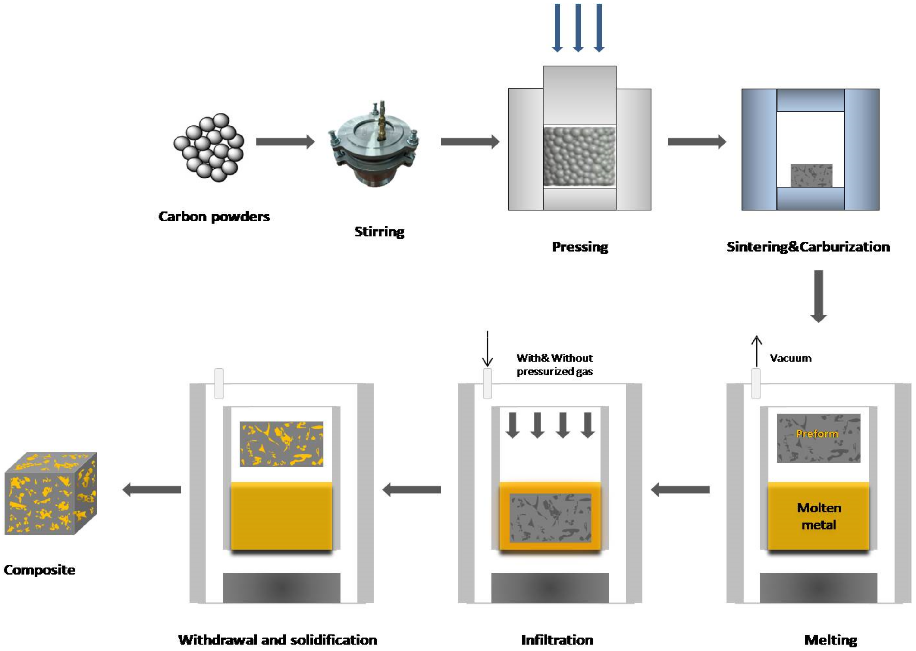
2. Infiltration Technology Preparation of Copper/Carbon Matrix Composites

The method of preparation is based on the infiltration of a prepared carbon preform in an enclosed and heated chamber with molten metal (Figure 1). A preform is usually immersed in a molten matrix metal under a vacuum after the infiltration temperature is reached. Then, the molten metal tends to fill the gaps between the dispersed reinforcing phases. An external pressure (usually inert gas) given to the liquid matrix phase can drive the infiltration process (pressure infiltration), or it can be driven by the capillary forces between the alloy and the dispersed carbon phase (pressureless infiltration).
In general, the biggest problem encountered during the research is the low wetting angle at the copper–carbon interface and the resulting weak interface bonding. Two methods usually come to the fore to solve this problem. The first is to strengthen the interfacial bond by doping carbide-forming elements into the copper metal alloy [31]. The second is to strengthen the interfacial bond by making modifications to the carbon preform. For example, Bo Kong [32] coated carbon preforms with chromium and was able to improve the wettability between carbon and copper surfaces by reducing the contact angle from 140° down to 60°.
In the pressure gas sintering case, in order to ensure that the pore structure of the preform is completely filled and to not hinder the preform deforming, pressures, supported by gas, typically do not exceed 15 MPa [33] because it is adequate to ensure full pore filling in the structure and that the preform is not subjected to deformation.
The infiltration temperature is usually used as high as possible for the used equipment. A key role is also played by the time of infiltration, thus affecting the reaction of the preform with the alloy via the carbide forming elements present in mixture.
Cu/carbon composite materials for electronics can be manufactured cost effectively using this method. As molten metals (and consequently elevated temperatures) increase the kinetics of interaction between metal and carbon via carbide forming elements, it is significant to take into the account the kinetics of infiltration as well as the chemical protection of the preform if the reaction kinetics are very rapid.

3. Current Stage of the Art of the Infiltration of Copper/Carbon Matrix

This part deals with the recent development in the field of the infiltration of carbon preform with copper. Even though this study focuses on a single method of sample preparation, the infiltration method, some differences still stand out. The most important of these are whether or not the external pressure is used during infiltration. For this reason, this part of the review is examined under two separate chapters. They are further divided by the fact regarding which part (matrix or carbon preform) was modified with carbide forming elements.
In this review part, the investigated characteristics and possible industrial applications are also mentioned.

3.1. Infiltration Technologies of Carbon Matrix without Pressure

3.1.1. Addition of Elements into Copper

In order to increase the wettability between the interfaces, the most preferred method is to alloy the copper. According to the literature, titanium is the most prominent as an alloying carbide forming element [34,35,36,37,38,39,40]. Apart from this, it has been observed that Cr and Si elements are also used [32,41,42]. In this chapter, one can find a comprehensive review of these studies.
Using the melting infiltration process under a vacuum, Yiwen Liu et al. [34] developed C/Cu composites. First, under a vacuum, the thermosetting phenolic resin was infiltrated into a continuous carbon fiber T300 (PAN) weave fabric in a self-made soak pot. After that, it was pyrolyzed at 773 K under Ar in a carbonization furnace. The processes were carried out twice again. It was possible to produce a porous C-C preform with a density of 1.3 g/cm3. Under a vacuum, in an electromagnetic induction melting furnace, a Cu alloy containing 1wt.%Cr and 8wt.%Ti was produced. Then, the C-C preform and Cu alloy were placed in the vacuum chamber of the electric furnace. Concerning the melting of the Cu alloy, the materials were heated to 1373 K after evacuation to 10−3 Pa. Ten minutes later, the alloy was fully melted. It was overheated to 1673 K and kept there for 30 min so that the molten alloy and preform could penetrate entirely with the Cu alloy.
Wetting between the Cu and C-C preform, as well as Cu’s capacity to infiltrate into the C-C preform, was considerably increased by the addition of Ti and Cr to the matrix alloy. Interfacial bonding and high density are hallmarks of the C/Cu composites that have been developed. Ti and C react with carbon fiber in the presence of copper to form TiC. When these composites are exposed to plasma or an electric arc, the cathode spots travel over the surface, resulting in mass loss and degradation of the materials’ properties. To better understand cathode spot behaviour on a carbon fiber reinforced copper matrix composite (Cf/Cu), the same research group [42] used high-speed digital video cameras and scanning electron microscopes. Vacuum arc erosion is more easily resisted by carbon fibers than by a copper matrix. Instead of following the carbon fibers, the cathode spot travels across the matrix. This type of Cf/Cu has fewer cathode spots than other types of Cf/Cu.
Zhang Huayu and Yiwen Liu [35] worked with the same materials and process to produce Cu-C composites. They examined the arc erosion resistance of these composites. Under a vacuum atmosphere, the arc erosion rate of a Cf/Cu composite was determined. Infiltration of Cu into the C/C preform was shown to be considerably enhanced by the addition of Ti and Cr, as observed by the outcomes. Fibers and matrix produced a TiC at the interface. Because of this, even after the material had been exposed to plasma, the fiber and matrix remained well-bonded. So, the carbon fibers prevented the composite from being highly eroded as a result of this. Cu, on the other hand, was fully depleted during the arc erosion process. As a result, the graphite had deteriorated to the point where it resembled cauliflower morphology. Because of this, the prepared Cf/Cu was able to withstand significantly higher arc erosion than the usual Cu-C material.
In another study published in 2015, Carlos R Rambo [36] tried to produce carbon preform via 3D printing. The electrical characteristics and microstructure of dense TiC/Ti-Cu/C composites were investigated. Preforms with 65–78% porosities were infiltrated by 50wt.%Cu-50wt.%Ti at 1373 K with flowing Ar gas.
The process resulted in the development of a composite that was mostly composed of TiC, binary intermetallic Ti-Cu phases, and residual carbon. Given the low electrical resistivity of the samples (ranging from 15 to 60 µΩcm), the newly developed TiC/Ti-Cu/C composites appear to be a very interesting choice for electrical-mechanical applications.
Use of this alloy with porous carbon preforms that can be machined via 3D printing in different shapes can attract new processing technologies with diverse applications, such as EDM electrodes.
Ti element is a good candidate as a dopant for Cu, since it can easily form a carbide layer between carbon and matrix. For this reason, K.X. Zhang et al. [37] examined the interfacial microstructures that are generated during the infiltration of carbon/carbon (C/C) composites with molten Cu-8wt.%Ti. Before infiltration, the Cu–Ti alloy was placed on top of the C/C preform with a volume ratio of approximately 2:1 between the alloy and the preform, before being infiltrated. After that, the pressureless infiltration procedure was carried out at 1373 K under a vacuum of 10 Pa with a holding time of 30 min. The short-cut fiber web zone has the following two types of interfaces: (i) a combination of fine-grained (FG) TiC and nanosized Cu particles, and (ii) a “Cu layer” with a thickness of max. 500 nm at the pyrolytic carbon (PyC)/coarse-grained (CG) TiC contact. The forming of the PyC/TiC and PyC/Cu2O interfaces, as well as the PyC/Cu2O interface, are the primary mechanisms for the two interfaces’ bonding.
For the purpose of manufacturing the sliding contact material, Cu–Ti alloys were infiltrated into the C/C matrix by Lin Yang [38]. Preforms made of porous carbon/carbon with a porosity of 20% were immersed in a crucible filled with copper and titanium powders mixed together. In the furnace, they were placed under a vacuum of 10−2 Pa and infiltration took place at 1573 K for 10 min. Mass fraction of copper within the composite was 28wt.%. There were comparisons of the C/C-Cu composite with a carbon/copper contact strip for the electrical, mechanical and tribological properties, respectively. This material has an advantage over the C/Cu strip in terms of mechanical and electrical properties due to its considerably lower electrical resistivity (0.58 m), better bending strength (186 MPa), along with its 4.7 J/cm2 impact strength. Compared to the C/Cu strip, the C/C-Cu composite was shown to have superior wear resistance and a lower risk of damaging the copper counterpart. As a result, the C/C-Cu-Ti combination has great promise for use as a new sliding electrical contact material.
Another group, led by Lihui Cui [39], from Beihang University, also worked on C-C/Cu composites for sliding contacts. In this study, the researchers used carbon fiber 2.5D-braided preforms. Powder Cu-Ti (10wt.%) and C/C preforms with 25% porosity were inserted in the furnace and heated to 1673 K under vacuum pressure for 1 h. As a result, outstanding electrical and mechanical properties were achieved by the C/C-Cu composite’s component phases (TiC), forming an excellent interconnected structure. A compression strength of 324 MPa, flexural strength of 215 MPa, and electrical resistance of 0.63 µΩm proved the composite’s mechanical and electrical superiority over the C/Cu composite strip. Hence, this material might be a good candidate for railway current collector applications.
A Cu–Ti alloy was used in this study [40]. The ablation properties of the C/C-Cu composite were investigated. Porous C/C composites were encased in a crucible with a mixture of Cu-10wt.%Ti powders. For 30 min, substances were held at 1573 K in a vacuum furnace so as to complete infiltration. The ablation of the Cu and TiC in the composite occurred prior to the mechanical denudation of the C/C composite when the process was carried out under an O2-C2H2 flame. The composite demonstrated superior ablation performance in terms of short-term anti-ablation when compared to a commonly used carbon/carbon composite.
Besides titanium, Si has attracted attention alongside copper and have been used to make the composite brake discs [41]. A preform was created by hot forming at 170 °C for 30 min at a high temperature. Then, they were pyrolyzed at 2000 °C in an inert gas atmosphere to complete the process. The liquid Si and Cu were infiltrated into the C/C composite after it had been heated to 1823 K under a vacuum. They discovered that the inclusion of copper increased thermal conductivity. Friction coefficients were the more stable in the C/C-SiC-CuxSiy discs than they were in the C/C-SiC discs.

3.1.2. Modification of Carbon Matrix

Although the option to modify the carbon matrix is not as popular as the alloying of the copper metal, some applications are available in the literature for this solution.
Wen Yan Zhou [43] focused his research on modifying a carbon matrix with Mo2C to improve the wettability between Cu and C/C. As a result, he published two related articles on this topic. He used an ammonium paramolybdate ((NH4)6Mo24·4H2O) with a 1:1 molar ratio of sodium chloride and potassium chloride, which was combined to form a flux. Mo2C coatings were created by burying the C/C preform in the prepared mixture and heating it to 1273 K for 60 min in an alumina crucible. Pure copper was introduced into the Mo2C-coated C/C preform at a temperature of 1573 K in a vacuum. In one study, the resulting Mo2C layers had a thickness of about 1 µm and covered the C/C preform’s internal pore surface equally. The non-wettable copper–carbon interface was changed into Mo2C/carbon and wettable Cu/Mo2C interfaces by the development of the Mo2C layer.
In the case of the other study [44], examination of the microstructure and characteristics of the C/C-Cu composites as a result of graphitization was carried out using two distinct types of preforms (with and without graphitized preforms). Because of the increased degree of graphitization, the C/C-Cu composite with graphitization has reduced electrical resistance, a lower friction coefficient, a lower thermal expansion coefficient, and a significantly higher thermal conductivity. Despite this, the material has lesser flexural strength, impact toughness, and the wear rate was higher. Mostly abrasive wear was observed in the graphitized composite, whereas adhesion wear was observed in the non-graphitized composite. Oxidation wear was observed for both composites.
Reactive melt infiltration (RMI) of the Cu–Ti alloy into porous C/C-SiC composites resulted in the formation of novel friction composites (C/C-Cu5Si-TiC) with improved friction properties [45]. Stacks of short fiber webs were needle-punched repeatedly. After that, chemical vapor infiltration (CVI) was used to create porous C/C composites at 1273 K for 120 h in an argon environment with an absolute pressure of 0.1 MPa. H2 was used as a carrier and diluting gas, while C3H6 used as commercial gas. Finally, the C/C-Cu5Si-TiC composites were prepared by performing a combined LSI (liquid silicon infiltration) and RMI procedure on the porous C/C composites. In order to obtain porous C/C-SiC composites, the LSI procedure was first carried out at 2023 K under a vacuum for 0.5 h. At 1573 K, the C/C-SiC composites were infiltrated by RMI in a vacuum (absolute pressure 1 Pa) for two hours. The RMI process was carried out using a mixture of Cu and Ti powders with a mass ratio of Cu/Ti = 90/10wt.%. The microstructure of the resulting composite revealed that it constituted a Cu5Si matrix reinforced by TiC particles and intact C/C structures. To put it another way, compared to C/C composites, the C/C-Cu5Si-TiC composite had better flexural strength, impact resistance, and thermal diffusivity.

3.2. Gas PressureInfiltration of Carbon Matrix

3.2.1. Addition of Elements into Copper

In the gas pressure infiltration methods, many elements, such as Si, B, Fe, are alloyed with copper with various concentrations in recently published papers.
Gionata Schneider and his team [46] have also worked on Cu infiltration of carbon preforms. The way of response at the interface between a solid porous ceramic and an infiltrating molten metal effects wetting was investigated. In particular, Cu 46 at.% of silicon at 1323–1473 K is required to transform silicon into graphite preforms with 22% porosity. The graphite combines with the silicon in the copper alloy to generate silicon carbide, which may be wetted more effectively by the alloy than the original graphite. According to the results, unlike what has observed in non-reactive systems, metal saturation cannot be stabilized when a constant applied pressure is used. The data can be used to derive an activation volume and an activation energy for the interfacial process that governs the reaction-driven motion of the triple line in this system, with the assumption that applied pressure influences the local rate of thermally activated triple line motion, as applied stress influences the rate of thermally activated dislocation motion.
In another study in Southwest Jiaotong University, China [47], boron was used as a dopant for Cu. Copper alloying with varying concentrations of the B element to form binary alloys to strengthen the bonding force between carbon and copper was effectively accomplished. Induction melting furnaces were used to make alloys with varying amounts of Cu-B (0, 1.2, and 2.5wt.%). To create the C/Cu composites, gas pressure infiltration was used. Cu–B alloys were cast into a graphite mould, heated to 1423 K under a vacuum of 10−2 Pa, and held at that temperature for 30 min to guarantee that the substances had melted completely.
A high-purity nitrogen atmosphere was then used to apply a pressure of 5 MPa for 30 min. In the experiments, it was discovered that the electrical conductivity and mechanical strength were proportional to the boron concentration; however, the contact angle was found to be inversely proportional to the amount of boron. Compared to unmodified composites, the flexural strength and electrical conductivity were both improved by 65% and 54%, respectively, when the doping amount was 2.5wt.%. The contact angle was also reduced to 21° when the doping amount was 2.5wt.%. According to the results, the presence of boron carbide at the interface with a modest thickness might strengthen the Cu/C interfacial bonding by converting it from physical bonding to chemical bonding. Boron is shown to increase the wettability of C/Cu systems in this work, leading to improved mechanical and electrical characteristics in Cu-B/sintered-carbon composites.
Previous work [47] was further expanded by doping 0.6–3.0wt.% boron into copper [48]. Cu–B (0, 0.6, 1.2, 2.5, and 3.0wt.%) alloys were placed in a graphite mould and heated to 1423 K in a high-temperature infiltration furnace under a vacuum level of 10−2 Pa for 1 h. Following that, a pressure of 8 MPa was applied in a nitrogen environment for 30 min, and the pressure was maintained throughout the whole process. Based on the results, it can be concluded that the flexural and compressive strengths of the modified composites were raised by 54% and 39%, respectively, and that the C/Cu contact angle fell from 123.6° to 21.3° when 2.5wt.% B doping was used.
Fe element was also one of the metals that was utilized to overcome copper and carbon’s limited wettability [49]. C/Cu-Fe composites with outstanding characteristics were produced using the gas pressure infiltration approach. The carbon preform and Cu-Fe (0, 3, and 6wt.%) alloy were preheated to 1473 K in a sintering furnace and left to dwell for 2 h before being used. Following complete melting of the Cu alloys, materials were pushed into the carbon substrate in an impregnating tank under a nitrogen pressure of 10 MPa to form a solid bond. The elemental Fe, which was dispersed between the carbon and the copper, reacted with the carbon to generate a Fe3C layer, which significantly increased the wettability of the carbon/copper combination. The contact angle diminished from 124° to 21° over the course of the experiment. The C/Cu-Fe composites have much higher compressive and flexural strengths when compared to composites without Fe doping, as well as electrical resistivity that is six times greater than the industry standard. Researchers found that introducing Fe3C into C/Cu composites is a good way to improve the mechanical properties of these materials.
A study held in 2010 [50] focused on Cf/Cu composite’s thermal conductivity and thermal expansion measurements in both the longitudinal and transversal directions. Preforms (Figure 2) had been placed in a high-pressure autoclave and preheated in a vacuum of 100 Pa before being used in the process. It was necessary to allow approximately 30 min for the system to thermally equilibrate, once the infiltration temperature of 1473 K had been reached. Afterwards, the fibre preforms were immersed in a graphite crucible filled with molten copper to complete the reaction. Nitrogen gas pressure was applied up to 6.0 MPa in 5 min, and the pressure was maintained (Figure 3). Thermal conductivities were reported as 650 Wm−1K−1 in the longitudinal direction and 60.7 Wm−1K−1 in the transversal directions, and the mean coefficients of thermal expansion were 0.8 × 10⁻⁶ K−1 in the longitudinal direction while 23.5 × 10⁻⁶ K−1 for transversal directions.
In a study from Japan, researchers utilized carbon-carbon preforms (C/C) with 20% porosity so as to infiltrate by pure copper [51]. Liquid copper was added to the low-cost C/C laminate to decrease porosity, enhance oxidation resistance, frictional characteristics, and wear resistance. Perpendicular stacked layers of carbon fibers were sintered via hot press. Then, Cu infiltration into C/C was carried out for around 20 min at temperatures of approximately 1473 K, pressures of 10 MPa, and with Ar gas. Infiltration of liquid copper into the C/C composites had a considerable impact on the tensile strength, stiffness, and fracture toughness of the composites, according to the results of this study.

3.2.2. Modification of Carbon Matrix

Fe2O3 and nickel were introduced into the carbon matrix and composites were obtained with the gas pressure infiltration method.
Ultrafine iron oxide (Fe2O3) was added by Wenfu Wei et al. [52] into the carbon matrix as a precursor in order to increase the interfacial bonding of carbon/copper composites made by pressure infiltration. The interface performance was, therefore, adjusted. The electro-mechanical properties of the impregnated carbon strip were also improved. The carbon matrix with varied Fe2O3 content (1wt.%, 3wt.%, 5wt.%, 7wt.%, and 9wt.%) is impregnated with the copper molten solution to produce the C/Cu composite pantograph strip. Compression moulding under 150 MPa with a 5-min dwell time in a cylindrical mould produced carbon powder and active element powder mixed together. Pressed samples were then heated in a carbonization furnace at 1357 K for 120 h, and various types of porous preforms were produced. Infiltration of the carbon matrix was carried out with 18 MPa pressure in the atmosphere, which was created by air and the molten metal was held at 1357 K for 3 min. In addition, a short study on an infiltration simulation in which the carbon preform is doped with WC was included. The composites’ electrical conductivity went up 140.8%, while the compressive and flexural strengths improved by 37.4% and 120.4%, respectively. This work will pave the way for the manufacturing of a new generation of pantograph strips for high-speed train railways.
The same research group led by Wenfu Wei expanded their previous work mentioned above by alloying the copper [53]. In the experiment, a crucible containing Cu-5wt.% Sn alloy was heated to 1473 K before the Fe2O3 doped carbon matrix was added. For 30 min, nitrogen gas from a cylinder was used to enter the carbon matrix. The pressure was set to 12 MPa. Iron carbide (Fe3C) significantly improved the interfacial bonding between copper and carbon. The contact angle between Cu and carbon was reduced from 124° to 38°, and the wettability was improved. Composites doped with 5wt.% Fe2O3 outperformed their unmodified counterparts. The compression and flexural strengths both increased by 37.4% and 120.4%, respectively. Compared to the previous work of the authors [38], while the mechanical properties remained the same, the electrical conductivity further improved in this study, with an increase of 283.7%.
The composite’s mechanical and electrical characteristics are limited due to the weak interfacial bonding force caused by the inherent non-wetting of the copper and carbon graphite matrix. Qianhua Liao et al. [54] intend to dope nickel into the carbon matrix to overcome this problem. Different contents of nickel (0wt.%, 1wt.%, 3wt.%, 5wt.%, 7wt.%) were added carbon matrix and then pressed at 150 MPa and sintered at 1300 °C for 2 h to obtain the preform. The Cu-10wt.% Sn alloy was infiltrated at 1523 K for 5 min with 18 MPa pressure into the carbon matrix. The carbon/copper modified composite’s porosity was notably decreased and was joined by a solid solution rather than mechanical interlock, resulting in a much better interfacial condition. The compressive strength and electrical conductivity of the composites were improved by about 52% and 35%, respectively, when the nickel concentration was 3wt.%.
Detailed information about the papers in which we discussed above are given in Table 1 and Table 2.

4. Observed Mechanical and Physical Properties of Cu/Carbon Composites

In comparison to unreinforced matrices, the papers show that the Cu/C composites have higher hardness, flexural strength, compressive strength and also other physical properties. There are a number of variables that are affecting the results, including alloy composition, matrix type and processing route. In order to generate Cu matrix composites with better strength, secondary phases must be introduced into Cu and its alloys. Forming an interface between metal and carbon results in a chemical bond, which makes it consume more energy during the damage process. As an alternative to the introduction of secondary phases to the copper alloy, changes in the carbon matrix are also made to improve the mechanical properties.
The used materials and technology variations significantly influence the final properties of the investigated composites. In particular, the creation of the interface between carbon and copper is mostly the result of the presence of carbide forming elements either in the carbon preform or as the copper alloy/admixed powder to copper. The trend is to use as small as possible size of carbide forming elements. For example, the highest flexural strength of 254.9 MPa is possessed by the composite where the carbon preform was coated with Mo2C [43], the carbon preform thickness was below 1 micron and interlayer thickness was around 1 micron.
The carbon preform is an important factor in determining the mechanical and physical properties of composites. The carbon preforms used in reviewed studies can be broadly divided into two categories, carbon/carbon preforms [37,38,51] and carbon preforms [48,49,50,53]. Although most of them are produced from carbon fibers [34,35,37,44,50,51], it has been observed in some cases that the starting material was carbon powder [47,52,53]. Apart from this, preforms produced with 3D printing [36] are slowly starting to be used by researchers also. Long [41] and short fibers [38,45] or continuous fibers [34] have been used in different studies. Moreover, these preforms were preferred to be knitted in some studies [34,35,51] and non-woven in others [37,38,39,40].
The preforms produced from powder consist of more than one raw material and the main components are mostly pitch coke powder, needle coke powder, carbon black, flake graphite, etc. [48,53]. Carbide-forming metal powders are added and mixed at this stage to create an interface in the preforms produced from powder, and it is aimed to ensure homogeneous distribution [52,53,54]. Generally, these preforms are moulded and sintered after pressing.
C/C preforms are formed by stacking on more than one layer [39,41,45,51] and then compacted with CVI [38,39,40,45] and CVD [43,44]. The preforms are often pyrolized (PyC) thus changing the carbon structure in preforms and also affecting the resulting interface phases after the infiltration process [37].
Interfacing and increasing wettability by applying coating to the preforms are also among the methods applied [43,44]. A few studies have been found in which the fibers are coated with phenolic resin [41,42]. The phenolic resin ensures that the carbon fiber remains intact during infiltration [42]. In one of these studies, the fibers were first coated with phenolic resin and then cut and mixed with phenolic resin powders [41].
It is evident that the raw material used, the degree of graphitization, pore size, density and porosity of the preform have significant effects on the infiltration quality.
In addition, the differences between the microstructures of the prepared composites are so different, due to the use of different raw materials, pyrolysis, coating, admixing of powders, that it is not possible to find any general connections between the structural/morphological findings and material performance.
Only general aspects, such as better interface bonding, Hall–Petch effects, homogeneity and anisotropy could be emphasized in general for this review. Therefore, the reader is referred to use Table 3 as a guideline for the further readings with regard to the microstructure properties’ dependence of particulate materials of interest.

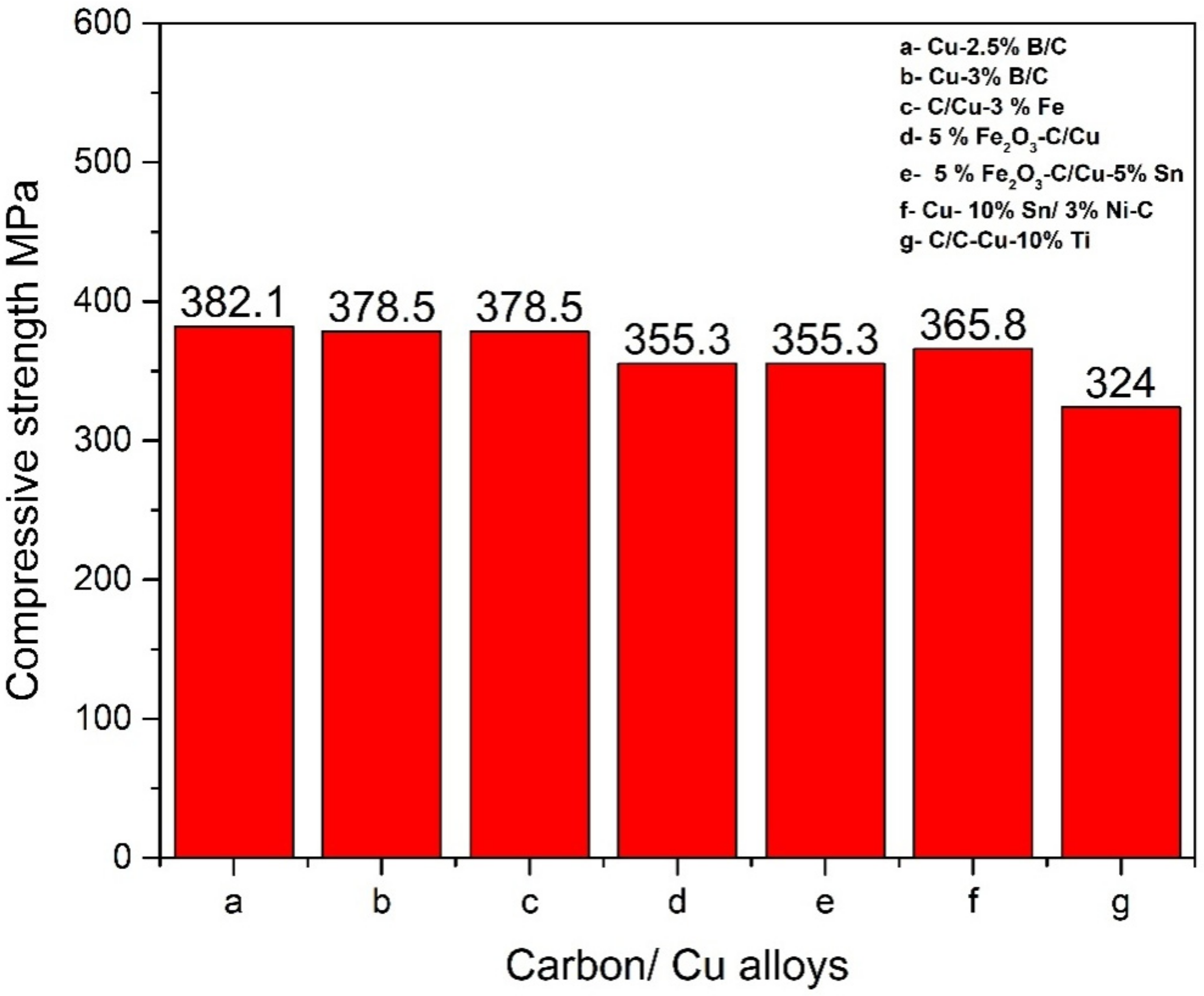
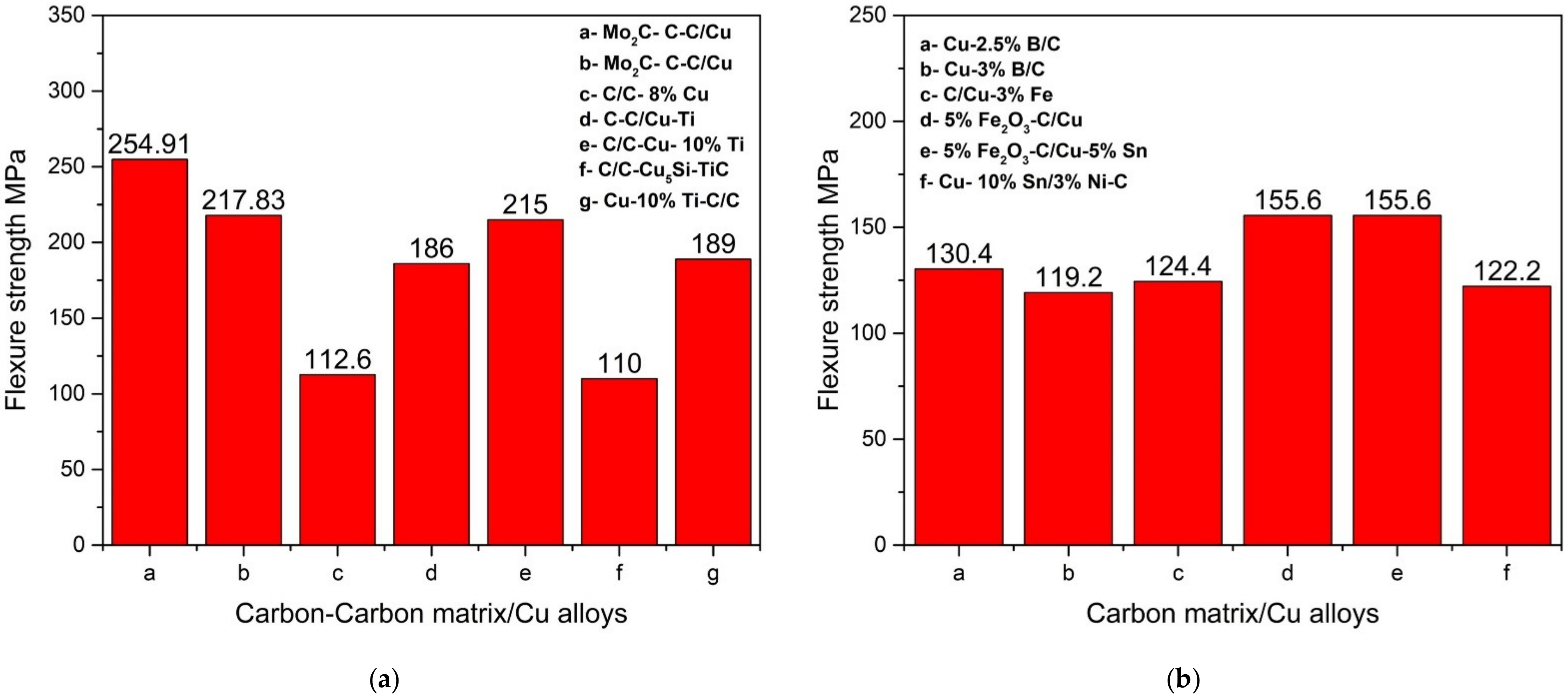
4.1. Mechanical Properties

The compressive strength is the capacity of a material or structure to withstand loads that tend to reduce one size of it. It is opposed to tensile strength, which withstands loads that tend to elongate one size of the sample. The compressive strength of copper is in the range of 45–330 MPa [56] depending on the compaction of starting powders, porosity, production method, pre and postproduction applications, such as rolling, extrusion, age-hardening, tempering and annealing. For example, Vijay Ponraj et al. observed a compressive strength of copper around 260 MPa [57]. The similar value above 250 MPa was found for extruded copper by Dean and Clyne [58]. A different work has been carried out by Hao Du [59], examining the compressive behaviour of lotus type copper samples with almost 50% porosity. Samples were manufactured by using a unidirectional solidification process to form porous copper with cylindrical pores. The results for compressive strength were below 30 MPa, which proves the fact that it depends on the production method and compressive strength exhibits various ranges of values. In order to support this, the compressive strength of the copper foam (70% pore) material obtained by the freeze casting method in a Korean-Hungarian co-produced article also resulted in the range of 20–29 MPa [60].
All of the investigate composites prepared by the infiltration technique possess a compressive strength higher than the compressive strength of pure copper. The lowest value was observed for the composite with 90wt.%Cu-10wt.% Ti-C/C, which was 324 MPa. As can be observed from the Figure 4, the highest compressive strength belongs to Cu-2.5wt.% B/C composite at 382 MPa.
Flexural strength is defined as the highest amount of bending stress that can be given to the material without it failing. In other words, it is normal stress that occurs in the material due to bending of the test sample in a flexural test. The test is usually carried out via three or four points bending.
All of the investigated composites possess flexural strength in the range of 110–260 MPa. The lowest value was observed for the composite with C/C-53.5wt.% Cu5Si-21wt.%TiC at 110 MPa. As can be observed from the Figure 5, the highest flexural strength belongs to Mo2C modified C-C/Cu composite at 255 MPa due to the small size of the carbon preform and interface layer.
The flexural strength is directly connected to the method of preparation, residual porosity and quality of the interface between the copper and carbon phase. The cracks on the interface lead to the reductions in the flexural strength of the investigated composites. Therefore, carbon-carbon matrix/Cu composites have in general higher flexural strength than simple carbon matrix/Cu composites.

4.1.1. Effect of Metal Alloying

Addition of boron (1.2wt.%, 2.5wt.%) into copper resulted in the improvement of the composites’ flexural strength by 8% and 54%, while compressive strength increased by 28% and 39%, respectively, in comparison to the Cu/C composite [47]. Later, this study was expanded by adding two more boron contents (0.6wt.%, 3wt.%) into copper. Between unmodified and 1.2wt.% B-Cu, 0.6wt.% exhibited slightly increases in both compressive and flexural strength, whereas this trend was not maintained in the case of 3wt.% B-Cu/C composites. When B content was increased from 2.5wt.% to 3wt.%, the compressive strength decreased from 382.1 MPa to 378.5 MPa, while flexural strength also decreased from 130.4 MPa to 119.2 MPa. Moreover, the elongation to the fracture rose from 1.4% to 1.5%. Improvements in mechanical properties are expected since wettability is better after adding boron into the alloy and forming an interlayer B4C. The decrease in the mechanical properties after 2.5wt.% was explained by the authors as follows: a thicker interface layer may cause the copper alloy to segregate and inhibit further infiltration into the carbon matrix, hence reducing the strengthening impact of copper compared to the composites. A thicker interlayer would also result in increased volume shrinkage and thermal stress during cooling, which might lead to a cohesive fracture and diminish the mechanical strength since the C, Cu, or B4C thermal expansion coefficients are significantly different [42].
C/Cu-3wt.% Fe is very close to the highest compressive strength, which is slightly below 380 MPa, with copper alloying with 10wt.% Titanium, on the other hand, resulted in low compressive strength around 320 MPa. In terms of flexural strength, the results were vice versa. The strength of Ti alloyed Cu composites was higher. Two different Cu-10wt.%Ti/C composites exhibit different flexural strengths and this can be explained by the differences in production processes leading to different microstructures and interfaces [39,40,49].

4.1.2. Effect of Carbon Preform Doping

Modifying the carbon matrix is another way to improve wettability and mechanical properties. Fe2O3 proved that enhancement of the mechanical properties in comparison to the regular carbon matrix obtained from the two related paper studies published by Wenfu Wei [52,53]. In addition, the 5wt.%Fe2O3-C/Cu composite has 355.3 MPa compressive strength, which is 37.4% higher than the undoped material and flexural strength is increased by 120.4% to 155.6 MPa. Higher mechanical strength before failure is achieved by the Fe3C interphase’s excellent load transfer between the Cu and carbon matrix. Moreover, in comparison to carbon, the strength of Fe3C is better [40]. The outcomes interpreted by the authors are as follows: lattice dislocations inside metal grains cause plastic deformation [61]. Because solid–solution alloying is efficient in the formation of blocks to the movement of lattice dislocations, the small addition of iron oxide content can strengthen the Cu–alloy, which results in the composites having a high strength. There is a noticeable decrease in both strengths for 7wt.% and 9wt.% Fe2O3 added composites, owing to the fact that agglomeration of the nanometric particles of the iron compound in the carbon matrix with a high-volume fraction occurs. In addition, thicker Fe3C interlayers would cause abnormal shrinkage and fracture development since their thermal expansion coefficients do not match. Hence, higher addition of Fe2O3 decreases the mechanical strength [62,63]. Addition of % Sn into Cu did not affect either the compressive or flexural strengths when these two articles were compared.
Mo2C modification of the carbon matrix is another method that has been carried out. Flexural strength is approximately 4 times higher than commercial C/Cu composites (42 MPa) currently being used as contact strip pantographs [43]. The same research group produced composites with low graphitization treatment to preforms and improved flexural strength around 500% with 254 MPa in comparison to commercial C/Cu composites pantographs [44]. Yet, composites with high graphitization treatment exhibited lower flexural strength around 190 MPa. According to W.Y. Zhou, the reason is that the high level graphitization caused the volume of the C/Cu layer to shrink, and the interfacial connection between the PyC(pyrolytic carbon) layers decreased, resulting in delamination of the PyC layers and decrease in flexural strength.
In the recent work published by Qianhua Liao et al. in 2020, 3wt.% nickel was doped into a carbon matrix for preparation of the carbon/Cu-10wt.%. Sn composites [54]. Compressive strength was improved significantly by 51.8% and flexural strength by 58%. However, when we compare it with another carbon matrix dope sample (Mo2C-C), it is noticed that its flexural strength is almost half, and although its compressive strength is close to these values, it is still less compared to the higher Mo2C doped composite.

4.2. Tribological Properties

Tribology studies the wear, friction and lubrication of two different surfaces, which are in contact in motion. Tribological properties of materials can be designated by the type of motion and sliding speed, thickness of interfacial substance, contact geometry and test environment (temperature, pressure force etc.) [64].
In general, the investigation of tribology properties in publications is due to the use of these composites as electrical contact materials, mostly in tram lines. Apart from this, these composites have potential products as brake discs for vehicles. Since these products are subject to high wear, they are expected to have good tribology properties. In addition, corrosion also falls within the scope of tribology because corrosive surfaces are subject to wear and loss mass. However, the subject of corrosion will not be covered here, due to the lack of data in the investigated papers.
Regarding the tribological properties of the composites studied, the production route did not always result in an increase in the coefficient of friction (Table 4).
The friction performance coefficient of friction decreased when the Cu alloy was infiltrated into the C/C preform from 0.152 to 0.169, which means the composites’ surface is exposed more to friction. In this case, after the friction test surfaces were examined, it was found that the sample had formed a thick coating of wear debris on its surface. However, the counterpart was unable to remove the C particles due to the strong interface interactions between the Cu and the TiC.
The C/C-Cu composites were found to have moderate-intensity adhesive wear compared to the C/C material, owing to the fact that these preforms are composed of 2.5D layers. The layer structure efficiently spread the friction stresses, preventing surface exfoliation and reducing adhesion [39]. It also had a minor effect on the Cu-C/C friction coefficient as a result of composite fabrication, with a slight decrease from 0.25 to 0.23 compared to the preform [51]. However, while the load or pressure used in the first study was 0.15 MPa, in the latter, it was 10 MPa. The effects of the applied contact loads on the result should not be ignored. In the case of Mo2C doped C-C/Cu, the authors revealed that the higher graphitization process improved the friction performance by decreasing the coefficient of friction from 0.251 to 0.203. If graphitization reduced, the composite tended to have stronger adhesion, leading to flake-like debris as a typical feature of adhesion wear. The 50 N load was applied for 2 h of the wear experiment [44]. B.C. Goo [41] reported friction coefficient results for C/C-SiC-Cu brake discs in the range of 0.32–0.47 under several conditions, such as initial speed (km/h), deceleration and initial temperature (see Table 4 below). These measurements were performed at various contact pressures (0.5, 0.6, and 0.7 MPa).
Table 4. Friction coefficient of infiltrated composites.
CompositeFriction Coefficient (-)Counter MaterialReference
Mo2C-C-C/Cu0.251(F:50 N)Pure Cu ring[44]
Cu-C/C0.23 (P: 10 MPa)Metal pin[51]
C/C-Cu-10wt.% Ti0.169 (F:15 N, P:0.15 MPa)Hardened steel[39]
C/C-SiC-Cu0.32–0.47(P: 0.5–0.7 MPa)Cu (24.5wt.%), Fe (19.8), C (14.3)[41]

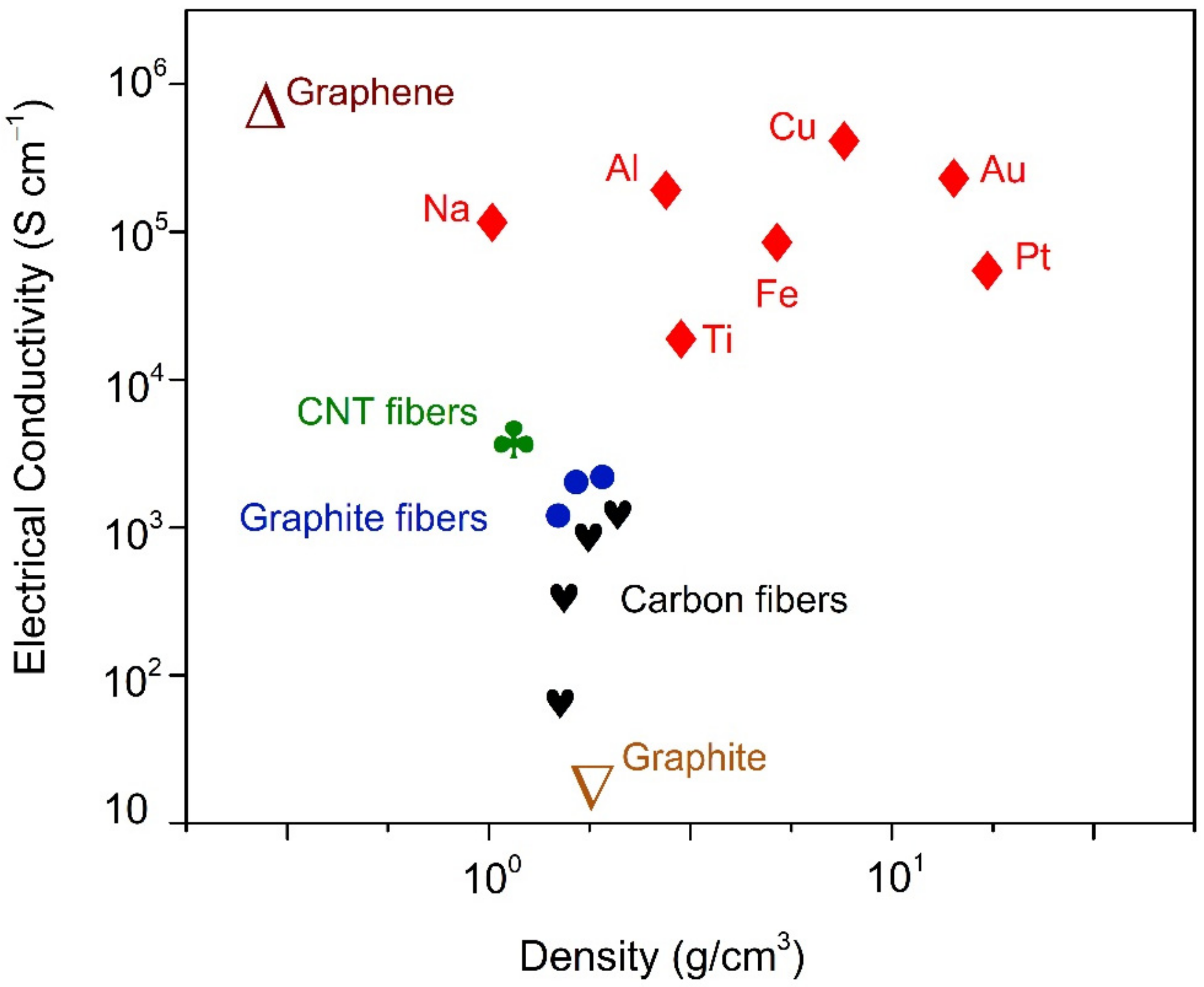
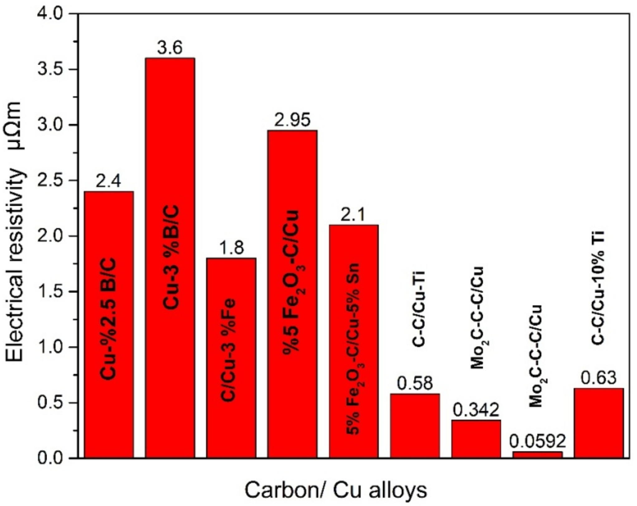
4.3. Electrical and Thermal Properties

The resistivity of a material is a measure of its resistance to electrical and thermal conduction for a specific substance. Conductors are materials that readily transmit electrical current and have low resistivity, which means that they are good conductors of electricity. Hence, this plays a major role in selecting materials for electrical applications.
Comparisons are presented in Figure 6 below between the electrical conductivities of the various types of carbon materials and those of other materials. On the basis of this figure, it may be concluded that CNT and graphene fibers may possess qualities that are comparable to or superior to those of metals. For the carbon fibers that have been constructed, a broad range of values has been found. Graphite is a non-metallic substance that has a less conductivity than metals (~103 S/cm) [65,66]. When compared to graphite, the conductivity of carbon fibers might be lower depending on the kind of precursor used, the method of synthesis, and the temperature at which the fibers are heated. Copper has high electrical conductivity (5.8 × 10⁵ S/cm) and combining with carbon type materials expected to result in better electrical properties [67].
Since the ability of a material to carry electrical current is measured by its resistivity, it is significant, therefore, to have knowledge about the electrical resistance of copper and carbon-based materials. In the literature, resistivity of carbon at room temperature is around 30–35 μΩm [68], whereas this property is substantially low for copper (about 0.0172 µΩm) [69]. Carbon fibers may be made more thermally and electrically conductive by coating them with a metal, since metals are more conductive than the fibers. Metal-coated carbon fibers are more electrically conductive than bare carbon fibers. For example, the electrical resistivity of PAN-based AS-4 (Hercules) carbon fiber is decreased considerably from 15.3 to 0.07 µΩm with nickel coating [70].
Similar cases were found in the reviewed studies. Composite materials produced from copper with high electrical conductivity and carbon are an efficient method to reduce electrical resistivity. According to the Figure 7, Mo2C-C-C/Cu composites have the best results among the others. Wenyan Zhou et al., explained this enhancement due to the fact that the presence of strong interfacial bonding and high PyC orientation in composite may result in dispersion of the current carrier induced by interface resistance effects and lattice defects, respectively [43,44]. They were able to decrease the resistivity from 29.732 to 0.0592 µΩm via coating preforms with molybdenum metal [43]. Both Cu-Ti metal matrix composites demonstrated significantly lower resistivity than commercial C/Cu strips, which demonstrates resistivity of 13.2 µΩm [38,39]. The addition of a small quantity of titanium, which generates TiC compounds at the interface, strengthens the chemical interactions between the copper and the C/C preform. An essential way to improve the composite’s physical qualities when the interface bonding is exceedingly poor is to increase the interfacial strength. The development of strong connections at the C–Cu interface would improve electronic conduction and stress conduction by increasing the cohesion. Electrical characteristics of the C/C-Cu composite have been increased consequently. When we look at the Cu-B alloy composites, the electrical resistance first decreased from 7.6 to 1.7 µΩm and then increased to 2.4 µΩm with the increasing B content [47]. Haozi Zuo, explained this situation as follows: in C/Cu composites, there are at first numerous conductivity phases. The impregnated phase is made up of the Cu–B alloy, while the matrix phase is made up of sintered carbon. These four types of bonds might be present simultaneously in the composites Cu-Cu, Cu-B semimetal, CuB-Cu covalent, and CuB-C covalent. There are two key factors influencing composite electrical conductivity, including volume percentage of the copper alloy and the carbon-copper contact. Composites with B element doping may have lower electrical resistivity because of their increased Cu–B alloy composition and better penetration degree, since the metallic component has a large impact on composite electrical resistivity. The rest of the composites have electrical resistivity between 2 and 3.6 µΩm.
Even with these results, composites have shown important development. It can be stated from the Figure 7 that in terms of electrical characteristics, the C/C-Cu composites clearly outperform the C/Cu composites. The reason behind this might be strongly connected to the structure between the C/C preform and the copper matrix, resulting in exceptional mechanical performance from the C/C-Cu composite. “Network conduction” can also be ascribed to the increased resistivity of the C/C-Cu composite, which has an interconnected structure and a unique electric conductive mechanism. When using this technique, the pure copper matrix acts as a conductor, and the carbon phase has almost no impact on that conductivity. Electrical conductivity increases due to the copper phase’s continuous network, which contains a small amount of interface phase and interfacial resistance. Moreover, when the interfacial connection is strong, there is not only in-phase carrier migration of the carbon phase and the copper phase, but also transboundary surface migration of the charge carrier. The interfacial layer thickness and the volume percentage of the molten phase are the primary factors that determine the extent to which the impact of interfacial bonding is exerted on the electron conductive behaviour of composites. Consequently, the thickness of the interfacial layer is a significant factor in determining the electron conductivity of Cu/C composites (note: this only applies if all other conditions are the same).
Thermal properties are crucial for applications such as electronic packaging and heat sinks. In order to avoid overheating, modern integrated circuits and other powerful electrical components need to be cooled down and distributed. Reliable and long-lasting performance is dependent on effective heat control.
Thermal properties for several allotropes of carbon and copper are given in Table 5 below. Data are collected from various references. Thermal conductivity (1.7 Wm−1K−1) and low coefficient of linear thermal expansion, CTE (1.1–1.3 × 10⁻⁶·K−1), are known properties of carbon [71,72].
Copper demonstrates thermal conductivity between 410 and 340 Wm−1K−1 from 0 to 927 °C, respectively [54]. Carbon fibers could be divided into three groups according to their production types, including polymer fibers (e.g., polyacrylonitrile, PAN), pitch fibers or carbonaceous gases. Yet, the most commonly preferred fibers are pitch and polymer-based ones. Although the structure of carbon fibers has a great influence on their properties, it is generally possible to state that carbon fibers have low thermal expansion coefficients. It can be observed from Table 4 that Cf from Hercules have negative value CTEs and thermal conductivity of 7.2 Wm−1K−1 [70] (p. 74).
When carbon is combined with copper, it may greatly enhance its thermal conductivity, while simultaneously decreasing the coefficient of thermal expansion (CTE). As a result, Cu/C composites have a high potential for application in thermal management.
Unfortunately, the provided values of thermal conductivity and CTE mostly do not confirm this trend and it is the drawback of the investigated composites (see Table 6). Wen Yan Zhou et.al realized that after graphitization, for the Mo2C-C-C/Cu at higher volume fractions of Cu, the thermal conductivity increased from 27.29 to 125.03 Wm−1K−1. On the other hand, the CTE value slightly decreased from 4.72 to 4.02. The reason behind this was that carbon was highly graphitized in this composite. The composite has a shorter phonon mean free path because of reduced defect-caused lattice wave scattering. According to the Grüneisen equation where CTE is related with isobaric specific heat (Cp), C/Cu would have a lower Cp, which means a lower thermal expansion coefficient with higher Cu [44]. In another study with Mo2C-C-C/Cu, the thermal conductivity improved more than 10 times with regard to C/C preforms with 12 Wm−1K−1 before infiltration. Because of the C/C-Cu composite’s connected structure through the interfaces, the unique electrically conductive process known as network conduction is developed [43]. Naďa Beronská and her colleagues used HM carbon fibres with 900–1000 Wm−1K−1 thermal conductivity and—1.5 × 10⁻⁶ CTE in the longitudinal direction. The thermal conductivity improved more than 60% in the longitudinal direction, since copper has conductivity of 400 Wm−1K−1 [50]. Addition of Cu caused a major impact on the thermal conductivity by reaching a value almost double in comparison to C/C-SiC, which was 45.9 Wm−1K−1 in the horizontal direction [41]. Liping Ran et al., also managed to enhance the thermal conductivity of C/C preforms by 26.1% via producing Cu-10wt.%Ti-C/C [40].

5. Industrial Applications

It has been stated by the authors of the published papers that the materials that emerged from the research works are candidates for use in many industrial areas, mainly in mechanical and electrical applications. Two of these application areas stand out significantly. Including sliding electrical contact materials, e.g., pantograph strips [39,43,47,52] and brake discs [41,45,51]. When these studies are examined in detail, it is striking that materials with at least the same and better properties than those used in the market were obtained. For example, as a result of the study conducted by Lin Yang et al. [38], novel C/C-Cu composites exhibit better electrical conductivity and bending strength than commercial C-Cu contact strips.
Besides the applications mentioned above, the authors proposed also the following industrial applications: wall surface shields in fusion devices, electric discharge machining electrodes, and sealing and electrical contact materials.

6. Summary and Future Direction

The researchers in the field of infiltration of carbon preforms with copper and copper alloys mostly copied the ideas of older works in this field during the past 12 years. The review indicates that in the past 2 years, the number of works and their citations is increasing in this field, above 30% for both.
Moreover, new trends in technologies and improvements were incorporated, such as the usage of ultra-fine particles and nanoparticles of carbide forming elements on the carbon–copper interface usually in the range of 500 nanometers to 3 microns (Table 3). It can be expected that the trend of using nano-sized carbide forming elements will increase in future works. Even previously well-known carbides, such as WC or TiC, ZrC, will be probably reconsidered again and used.
Another aspect involves the use of recently developed technologies, such as spark plasma sintering for the preparation of carbon preforms. In this field, it can be expected that additive manufacturing technologies for the preparation of complex 3D carbon preforms with controlled pore size (important for perfect infiltration) will be used more often in the near future.
The alloying of copper will be probably based on computation techniques that will also employ artificial intelligence to determine the best alloying elements and their wt.% in copper to achieve the best wettability at the lowest possible infiltration temperature.
This will enable us to produce cost effectively and most simply large complex parts of very good quality for the energy sector, transportation and electronic components, thus decreasing the carbon footprint and energy requirements.

Author Contributions

S.B.C.; resources, data collection, writing—original draft preparation, J.K.; writing—review and editing, visualization, supervision, project administration. All authors have read and agreed to the published version of the manuscript.

Funding

This research was funded by Slovak Academy of Sciences project No. 1907 (Project: “Changes in the interface microstructure of copper-based composite materials with a carbon skeleton prepared by gas pressure infiltration”).

Institutional Review Board Statement

Not applicable.

Informed Consent Statement

Not applicable.

Data Availability Statement

Not applicable.

Conflicts of Interest

The authors declare no conflict of interest.

References

  1. Dong, L.; Chen, W.; Zheng, C.; Deng, N. Microstructure and properties characterization of tungsten-copper composite materials doped with graphene. J. Alloys Compd. 2017, 695, 1637–1646. [Google Scholar] [CrossRef]
  2. Dong, L.; Chen, W.; Deng, N.; Song, J.; Wang, J. Investigation on arc erosion behaviors and mechanisms of W70Cu30 electrical contact materials adding graphene. J. Alloys Compd. 2017, 696, 923–930. [Google Scholar] [CrossRef]
  3. Cui, Y.; Wang, L.; Li, B.; Cao, G.; Fei, W. Effect of ball milling on the defeat of few-layer graphene and properties of copper matrix composites. Acta Metall. Sin. 2014, 27, 937–943. [Google Scholar] [CrossRef]
  4. Li, M.; Che, H.; Liu, X.; Liang, S.; Xie, H. Highly enhanced mechanical properties in Cu matrix composites reinforced with graphene decorated metallic nanoparticles. J. Mater. Sci. 2014, 49, 3725–3731. [Google Scholar] [CrossRef]
  5. Hwang, J.; Yoon, T.; Jin, H.; Lee, J.; Kim, T.S.; Hong, S.H.; Jeon, S. Enhanced mechanical properties of graphene/copper nanocomposites using a molecular-level mixing process. Adv. Mater. 2013, 25, 6724–6729. [Google Scholar] [CrossRef]
  6. Jagannadham, K. Volume fraction of graphene platelets in copper-graphene composites. Metall. Mater. Trans. A 2013, 44, 552–559. [Google Scholar] [CrossRef]
  7. Koltsova, T.S.; Nasibulina, L.I.; Anoshlin, I.V. New hybrid copper composite materials based on carbon nanostructures. J. Mater. Sci. Eng. B 2012, 2, 240–246. [Google Scholar]
  8. Nasibulin, A.G.; Koltsova, T. A novel approach to composite preparation by direct synthesis of carbon nanomaterial on matrix or filler particles. Acta Mater. 2013, 61, 1862–1871. [Google Scholar] [CrossRef]
  9. Yin, S.; Zhang, Z.; Ekoi, E.J.; Wang, J.J.; Dowling, D.P.; Nicolosi, V. Novel cold spray for fabricating graphene reinforced metal matrix composites. Mater. Lett. 2017, 196, 172–175. [Google Scholar] [CrossRef]
  10. Jagannadham, K. Orientation dependence of thermal conductivity in copper-graphene composites. J. Appl Phys. 2011, 110, 074901. [Google Scholar] [CrossRef]
  11. Kim, Y.; Lee, J.; Yeom, M.S. Strengthening effect of single-atomic-layer graphene in metal–graphene nanolayered composites. Nat. Commun. 2013, 4, 2114. [Google Scholar] [CrossRef] [PubMed]
  12. Xiong, D.B.; Cao, M.; Guo, Q.; Tan, Z.; Fan, G. Graphene-and-copper artificial nacre fabricated by a preform impregnation process: Bioinspired strategy for strengthening-toughening of metal matrix composite. Acs Nano 2015, 9, 6934–6943. [Google Scholar] [CrossRef] [PubMed]
  13. Liu, X.; Wei, D.; Zhuang, L. Fabrication of high-strength graphene nanosheets/Cu composites by accumulative roll bonding. Mater. Sci. Eng. A 2015, 642, 1–6. [Google Scholar] [CrossRef]
  14. Blawert, C. Noble and Nonferrous Metal Matrix Composite Materials. In Metal Matrix Composites: Custom-Made Materials for Automotive and Aerospace Engineering; Kainer, K.U., Ed.; WILEY-VCH Verlag GmbH & Co. KGaA: Weinheim, Germany, 2006; pp. 295–307. [Google Scholar]
  15. Stöckel, D. Verbundwerkstoffe; Bartz, W.J., Wippler, E., Eds.; Lexika-Verlag: Munich, Germany, 1978. [Google Scholar]
  16. Nicolas, E.; Michael, G.; Nicholas, M.G.; Drevet, B. Wettability at High Temperatures; Cahn, R.W., Ed.; Pergamon Materials Series; Elsevier: Oxford, UK, 1999. [Google Scholar]
  17. Piñero, E.; Molina, J.M.; Narciso, J.; Louis, E. Liquid metal infiltration into ceramic particle compacts chemically and morphologically heterogeneous. Mater. Sci. Eng. A 2008, 495, 288–291. [Google Scholar] [CrossRef]
  18. Manu, K.M.S.; Raag, L.A.; Rajan, T.P.D.; Gupta, M.; Pai, B.C. Liquid Metal Infiltration Processing of Metallic Composites: A Critical Review. Metall. Mater. Trans. B 2016, 47, 2799–2819. [Google Scholar] [CrossRef]
  19. Cook, A.J.; Werner, P.S. Pressure infiltration casting of metal matrix composites. Mater. Sci. Eng. A 1991, 144, 189–206. [Google Scholar] [CrossRef]
  20. Blucher, J.T. Discussion of a liquid metal pressure infiltration process to produce metal matrix composites. J. Mater. Process. Technol. 1992, 30, 381–390. [Google Scholar] [CrossRef]
  21. Etemadi, R.; Wang, B.; Pillai, K.M.; Niroumand, B.; Omrani, E.; Rohatgi, P. Pressure infiltration processes to synthesize metal matrix composites–A review of metal matrix composites, the technology and process simulation. Mater. Manuf. Processes 2018, 33, 1261–1290. [Google Scholar] [CrossRef]
  22. Sikhar, G.; Himanshu, B. A review on copper-graphite composite material fabrication & its mechanical properties. Int. J. Adv. Res. Innov. Ideas Educ. 2016, 2, 594–599. [Google Scholar]
  23. Hidalgo-Manrique, P.; Lei, X.; Xu, R.; Zhou, M.; Kinloch, I.A.; Young, R.J. Copper/graphene composites: A review. J. Mater. Sci. 2019, 54, 12236–12289. [Google Scholar] [CrossRef] [Green Version]
  24. Subramaniam, C.; Yamada, T.; Kobashi, K.; Sekiguchi, A.; Futaba, D.N.; Yumura, M.; Hata, K. One hundred fold increase in current carrying capacity in a carbon nanotube–copper composite. Nat. Commun. 2013, 4, 2202. [Google Scholar] [CrossRef] [PubMed] [Green Version]
  25. Subramaniam, C.; Yasuda, Y.; Takeya, S.; Ata, S.; Nishizawa, A.; Futaba, D.; Hata, K. Carbon nanotube-copper exhibiting metal-like thermal conductivity and silicon-like thermal expansion for efficient cooling of electronics. Nanoscale 2014, 6, 2669–2674. [Google Scholar] [CrossRef] [PubMed]
  26. Arnaud, C.; Lecouturier, F.; Mesguich, D.; Ferreira, N.; Chevallier, G.; Estournès, C.; Laurent, C. High strength—High conductivity double-walled carbon nanotube—Copper composite wires. Carbon 2016, 96, 212–215. [Google Scholar] [CrossRef] [Green Version]
  27. Xu, G.; Zhao, J.; Li, S.; Zhang, X.; Yong, Z.; Li, Q. Continuous electrodeposition for lightweight, highly conducting and strong carbon nanotube-copper composite fibers. Nanoscale 2011, 3, 4215–4219. [Google Scholar] [CrossRef]
  28. Sundaram, R.M.; Sekiguchi, A.; Sekiya, M.; Yamada, T.; Hata, K. Copper/carbon nanotube composites: Research trends and outlook. R. Soc. Open Sci. 2018, 5, 180814. [Google Scholar] [CrossRef] [PubMed] [Green Version]
  29. Janas, D.; Liszka, B. Copper matrix nanocomposites based on carbon nanotubes or graphene. Mater. Chem. Front. 2018, 2, 22–35. [Google Scholar] [CrossRef]
  30. Bakshi, S.R.; Lahiri, D.; Agarwal, A. Carbon nanotube reinforced metal matrix composites-a review. Int. Mater. Rev. 2010, 55, 41–64. [Google Scholar] [CrossRef]
  31. Léger, A.; Weber, L.; Mortensen, A. Influence of the wetting angle on capillary forces in pressure infiltration. Acta Mater. 2015, 91, 57–69. [Google Scholar] [CrossRef] [Green Version]
  32. Kong, B.; Ru, J.; Zhang, H.; Fan, T. Enhanced wetting and properties of carbon/carbon-Cu composites with Cr3C2 coatings by Cr-solution immersion method. J. Mater. Sci. Technol. 2018, 34, 458–465. [Google Scholar] [CrossRef]
  33. Paulo Davim, J. Metal Matrix Composites, Materials, Manufacturing and Engineering; De Gruyter: Berlin, Germany, 2014; pp. 4–5. [Google Scholar]
  34. Liu, Y.; Zhang, C.; Qiao, S.; Yang, Z. Fabrication and microstructure of C/Cu composites. Adv. Eng. Mater. 2010, 12, 493–496. [Google Scholar] [CrossRef]
  35. Zhang, H.; Liu, Y.; Zhao, X.; Luan, X. Preparation and arc erosion resistance of Cf/Cu composite by vacuum melting infiltration. J. Wuhan Univ. Technol. Mater. Sci. Ed. 2014, 29, 1039–1043. [Google Scholar] [CrossRef]
  36. Rambo, C.R.; Travitzky, N.; Greil, P. Conductive TiC/Ti–Cu/C composites fabricated by Ti–Cu alloy reactive infiltration into 3D-printed carbon performs. J. Compos. Mater. 2015, 49, 1971–1976. [Google Scholar] [CrossRef] [Green Version]
  37. Zhang, K.X.; Guo, X.S.; Zhao, W.K.; Zhang, F.Q.; He, L.L. TEM study on the microstructure of the interface at the scale of nanometer formed between Cu-8wt.% Ti melt and C/C preform. Mater. Chem. Phys. 2020, 246, 122795. [Google Scholar] [CrossRef]
  38. Yang, L.; Ran, L.; Yi, M. Carbon fiber knitted fabric reinforced copper composite for sliding contact material. Mater. Des. 2011, 32, 2365–2369. [Google Scholar] [CrossRef]
  39. Cui, L.; Luo, R.; Wang, L.; Luo, H.; Deng, C. Novel copper-impregnated carbon strip for sliding contact materials. J. Alloys Compd. 2018, 735, 1846–1853. [Google Scholar] [CrossRef]
  40. Ran, L.; Peng, K.; Yi, M.; Yang, L. Ablation property of a C/C–Cu composite prepared by pressureless infiltration. Mater. Lett. 2011, 65, 2076–2078. [Google Scholar] [CrossRef]
  41. Goo, B.C. Tribological Properties of a C/C–SiC–Cu Composite Brake Disc. J. Frict. Wear 2017, 38, 455–461. [Google Scholar] [CrossRef]
  42. Zhang, C.; Liu, Y.; Yang, Z.; Chen, L.; Qiao, S. Cathode spot movement on a continuous carbon fiber reinforced Cu matrix composite in vacuum. Vacuum 2013, 93, 45–49. [Google Scholar] [CrossRef]
  43. Zhou, W.; Yi, M.; Peng, K.; Ran, L.; Ge, Y. Preparation of a C/C–Cu composite with Mo2C coatings as a modification interlayer. Mater. Lett. 2015, 145, 264–268. [Google Scholar] [CrossRef]
  44. Zhou, W.Y.; Peng, K.; Ran, L.P.; Ge, Y.C.; Yi, M.Z. Effect of Graphitization on the Microstructure and Properties of Mo2C-Modified C/C–Cu Composites. Adv. Eng. Mater. 2016, 18, 1017–1021. [Google Scholar] [CrossRef]
  45. Xiao, P.; Lu, Y.H.; Liu, Y.Z.; Li, Z.; Fang, H.C.; Zhou, W.; Li, Y. Microstructure and properties of Cu-Ti alloy infiltrated chopped Cf reinforced ceramics composites. Ceram. Int. 2017, 43, 16628–16637. [Google Scholar] [CrossRef]
  46. Schneider, G.; Weber, L.; Mortensen, A. Reactive pressure infiltration of Cu-46at. pct. Si into carbon. Acta Mater. 2019, 177, 9–19. [Google Scholar] [CrossRef]
  47. Zuo, H.; Wu, G.; Li, X.; Huang, Z.; Wei, W.; Yang, Z. Improvement of Interfacial Wetting and Mechanical Electrical Properties of Cu-B/sintered-carbon Composites. In Proceedings of the 2021 International Conference on Electrical Materials and Power Equipment (ICEMPE), Chongqing, China, 11–15 April 2021; pp. 1–4. [Google Scholar]
  48. Zuo, H.; Wei, W.; Yang, Z.; Li, X.; Ren, J.; Xian, Y.; Wu, G. Performance enhancement of carbon/copper composites based on boron doping. J. Alloys Compd. 2021, 876, 160213. [Google Scholar] [CrossRef]
  49. Zuo, H.; Wei, W.; Li, X.; Yang, Z.; Liao, Q.; Xian, Y.; Wu, G. Enhanced wetting and properties of Carbon/Copper composites by Cu-Fe alloying. Compos. Interfaces 2022, 29, 111–120. [Google Scholar] [CrossRef]
  50. Beronská, N.; Štefánik, P.; Iždinský, K. Thermal Conductivity and Thermal Expansion of Copper Matrix Composites Reinforced with High Modulus C Fibres. Defect Diffus. Forum 2010, 297, 820–825. [Google Scholar] [CrossRef]
  51. Wang, W.X.; Takao, Y.; Matsubara, T. Tensile strength and fracture toughness of C/C and metal infiltrated composites Si–C/C and Cu–C/C. Compos. Part A Appl. Sci. Manuf. 2008, 39, 231–242. [Google Scholar] [CrossRef]
  52. Wei, W.; Li, X.; Liao, Q.; Zuo, H.; Yang, Z.; Wu, G. Electro-mechanical Performance Improvement of Pantograph Strip for High-speed Railway. In Proceedings of the 2021 International Conference on Electrical Materials and Power Equipment (ICEMPE), Chongqing, China, 11–15 April 2021; pp. 1–4. [Google Scholar]
  53. Zuo, H.; Wei, W.; Yang, Z.; Li, X.; Xie, W.; Liao, Q.; Wu, G. Synchronously improved mechanical strength and electrical conductivity of Carbon/Copper composites by forming Fe3C interlayer at C/Cu interface. Mater. Today Commun. 2021, 28, 102661. [Google Scholar] [CrossRef]
  54. Liao, Q.; Wei, W.; Zuo, H.; Li, X.; Yang, Z.; Xiao, S.; Wu, G. Interfacial bonding enhancement and properties improvement of carbon/copper composites based on nickel doping. Compos. Interfaces 2021, 28, 637–649. [Google Scholar] [CrossRef]
  55. Liu, L.; Li, H.; Shi, X.; Feng, W.; Feng, B.; Sun, C. Effect of Cu particles on the ablation properties of C/C composites. Solid State Sci. 2013, 25, 78–84. [Google Scholar] [CrossRef]
  56. Davis, J.R. Cast copper and copper alloys. In ASM Specialty Handbook Copper and Copper Alloys; ASM International: Materials Park, OH, USA, 2001; p. 98. [Google Scholar]
  57. Ponraj, N.V.; Azhagurajan, A.; Vettivel, S.C.; Shajan, X.S.; Nabhiraj, P.Y.; Sivapragash, M. Graphene nanosheet as reinforcement agent in copper matrix composite by using powder metallurgy method. Surf. Interfaces 2017, 6, 190–196. [Google Scholar] [CrossRef]
  58. Dean, J.; Clyne, T.W. Extraction of plasticity parameters from a single test using a spherical indenter and FEM modelling. Mech. Mater. 2017, 105, 112–122. [Google Scholar] [CrossRef]
  59. Du, H.; Cui, C.; Liu, H.; Song, G.; Xiong, T. Improvement on compressive properties of lotus-type porous copper by a nickel coating on pore walls. J. Mater. Sci. Technol. 2020, 37, 114–122. [Google Scholar] [CrossRef]
  60. Hong, K.; Kádár, C.; Knapek, M.; Drozdenko, D.; Jenei, P.; Kim, M.Y.; Gubicza, J. Comparison of morphology and compressive deformation behavior of copper foams manufactured via freeze-casting and space-holder methods. J. Mater. Res. Technol. 2021, 15, 6855–6865. [Google Scholar] [CrossRef]
  61. Chu, K.; Jia, C.C.; Jiang, L.K.; Li, W.S. Improvement of interface and mechanical properties in carbon nanotube reinforced Cu–Cr matrix composites. Mater. Des. 2013, 45, 407–411. [Google Scholar] [CrossRef]
  62. Zhao, M.; Feng, W.; Li, C.; Xiu, W.; Li, M.; Liu, S.; Wang, L.; Huang, W.; Zhao, Q. Thermally conductive, mechanically strong dielectric film made from aramid nanofiber and edge-hydroxylated boron nitride nanosheet for thermal management applications. Compos. Interfaces 2020, 8, 1067–1080. [Google Scholar]
  63. Jiang, X.; Fang, H.C.; Xiao, P.; Liu, T.; Zhu, J.M.; Wang, Y.C.; Liu, P.F.; Li, Y. Influence of carbon coating with phenolic resin in natural graphite on the microstructures and properties of graphite/Cu composites. J. Alloys Compd. 2018, 744, 165–173. [Google Scholar] [CrossRef]
  64. Takadoum, J. Materials for Tribology. In Materials and Surface Engineering in Tribology; Béguin, V., Ed.; John Wiley & Sons: Hoboken, NJ, USA, 2013; pp. 109–113. [Google Scholar]
  65. Koo, C.M.; Shahzad, F.; Kumar, P.; Yu, S.; Lee, S.H.; Hong, J.P. Polymer-based EMI shielding materials. In Advanced Materials for Electromagnetic Shielding: Fundamentals, Properties, and Applications; Kuruvilla, J., Wilson, R., Gejo, G., Eds.; Wiley: Hoboken, NJ, USA, 2018; pp. 177–217. [Google Scholar]
  66. Bhattacharjee, Y.; Biswas, S.; Bose, S. Thermoplastic polymer composites for EMI shielding applications. In Materials for Potential EMI Shielding Applications: Processing, Properties and Current Trends; Elsevier: Oxford, UK, 2019. [Google Scholar]
  67. Cesano, F.; Uddin, M.J.; Lozano, K.; Zanetti, M.; Scarano, D. All-carbon conductors for electronic and electrical wiring applications. Front. Mater. 2020, 7, 219. [Google Scholar] [CrossRef]
  68. Giancoli, D.C. Physik; Pearson Deutschland GmbH: Hallbergmoos, Germany, 2006. [Google Scholar]
  69. DeLand, F.H. CRC Handbook of Chemistry and Physics; West, R.C., Astle, M.J., Beyer, W.H., Eds.; CRC Press, Inc.: Boca Raton, FL, USA, 1983; p. 2386. [Google Scholar]
  70. Chung, D. Properties of Carbon Fibers. In Carbon Fiber Composites; Butterworth-Heinemann: Waltham, MA, USA, 2012; p. 74. [Google Scholar]
  71. Carvill, J. Thermodynamics and heat transfer. In Mechanical Engineer’s Data Handbook; Butterworth-Heinemann: Waltham, MA, USA, 1994. [Google Scholar]
  72. Engineering Toolbox. Thermal Expansion—Linear Expansion Coefficients. 2003. Available online: https://www.engineeringtoolbox.com/linear-expansion-coefficients-d_95.html (accessed on 29 May 2022).
  73. Dunn, B.D. Materials and Processes: For Spacecraft and High Reliability Applications; Springer: Cham, Switzerland, 2016. [Google Scholar]
  74. Engineering Toolbox. Solids, Liquids and Gases—Thermal Conductivities. 2003. Available online: https://www.engineeringtoolbox.com/thermal-conductivity-d_429.html (accessed on 29 May 2022).
  75. Kidalov, S.V.; Shakhov, F.M. Thermal conductivity of diamond composites. Materials 2009, 2, 2467–2495. [Google Scholar] [CrossRef] [Green Version]
Figure 1. Gas infiltration process.
Energies 15 05227 g001
Figure 2. SEM images of long carbon fibers K1100 typically used for the preparation of carbon preform: (a) 100× magnification image; (b) 1000× magnification image (IMMS SAS).
Energies 15 05227 g002
Figure 3. SEM microstructure of prepared Cf/Cu composites: (a) longitudinal to fibers; (b) perpendicular to fibers (IMMM SAS).
Energies 15 05227 g003
Figure 4. Compressive strength of composites (a: [47]; b: [48]; c: [49]; d: [52]; e: [53]; f: [54]; g: [39]).
Energies 15 05227 g004
Figure 5. (a) Flexural strength of C/C matrix-Cu composites (a: [44]; b: [43]; c: [55]; d: [38]; e: [39]; f: [45]; g: [40]); (b) carbon matrix/Cu composites (a: [47]; b: [48]; c: [49]; d: [52]; e: [53]; f: [54]).
Energies 15 05227 g005
Figure 6. Electrical conductivity of materials [67] (p. 17).
Energies 15 05227 g006
Figure 7. Electrical resistivity of carbon/Cu composites.
Energies 15 05227 g007
Table 1. Used starting materials, composition and their properties.
PreformAlloy wt.%Preform
Density (g/cm3)
Preform
Porosity
References
Porous C-C preformCu-%1 Cr-%8Ti1.30-[34]
Porous Cf preformCu-%1 Cr-%8Ti1.30-[35]
Carbon preformCu-%50–Ti-% 501.8065–78[36]
Porous C-C preformCu-8% Ti--[37]
Porous C-C preformCu, Ti powder-20[38]
Porous C-C preformCu-10% Ti powder1.7025[39]
Porous C-C preformCu-10% Ti powder1.606.1[40]
C/C preformCu, Si1.70-[41]
Porous C-C preformCu-%1 Cr-%8Ti1.30-[42]
Mo2C-coated C/CpreformPure Cu1.20-[43]
Mo2C/C-C preformPure Cu1.50-[44]
Porous C-C/SiC preformCu-10% Ti powder1.2037.7[45]
Porous CarbonCu-46 at.pct Si-22[46]
Carbon preformCu-1.2; 2.5% B1.4222.3[47]
Carbon preformCu-B (0, 0.6, 1.2, 2.5, and 3.0wt.%)1.4222.3[48]
Carbon preformCu-% 0, 3, 6 Fe 1.6020.4[49]
C fibresPure Cu2.20-[50]
C/C preformPure Cu1.7020[51]
Carbon matrix(%1-3-5-7-9 Fe2O3; % 0.15 WC)Pure Cu-44.35[52]
Fe2O3 doped porous C-C preformCu-5% Sn1.40–1.48 25.2–24.5 [53]
Nickel-doped carbon matrixCu-10% Sn1.32–1.51 33–25[54]
Cf-Cf preformCuSO4 solution1.81-[55]
Table 2. Infiltration properties of materials in the literature.
Infiltration
Pressure and Atmosphere
Infiltration
Temperature
Infiltration
Duration
Density (g/cm3)Porosity %Interface after InfiltrationReferences
10−3 Pa under Vacuum1400 °C30 min7.34-TiC[34]
10−3 Pa under Vacuum1400 °C30 min--TiC[35]
Argon atmosphere1100 °C30 min--TiC[36]
10 Pa under vacuum1100 °C30 min--TiC, Cu2O[37]
10−2 Pa under vacuum1300 °C10 min2.9-TiC[38]
10−2 Pa under vacuum1400 °C1 h3.8-TiC[39]
Vacuum1300 °C30 min2.92.4TiC[40]
Vacuum1600 °C-2.17-SiC, Cu3Si[41]
10−3 Pa under Vacuum1400 °C30 min--TiC[42]
Vacuum1573 °K-5.02-Mo2C[43]
Vacuum1300 °C-3.41–4.14-Mo2C[44]
Vacuum pressure < 1 Pa1300 °C2 h3.53–3.665.8–6.2Cu5Si, TiC, SiC[45]
1.1–1.2–1.3–1.4–12 MPa under Ar1050 °C–1100 °C–1150 °C–1200 °C160–190 min--SiC, Cu3Si[46]
5 MPa under N21150 °C30 min2.79–3.45–3.582.8–1.3–0.9B4C[47]
8 MPa under N21150 °C30 min2.79–3.582.8–0.9B4C[48]
10 MPa under N21200 °C-2.8–3.1–3.35.2–1.6–1.3Fe3C[49]
6 MPa under N21200 °C5 min---[50]
10 MPa under Ar1200 °C20 min2.689-[51]
18 MPa under Air1084 °C3 min-12.1–4.8Fe3C[52]
12 MPa under N21200 °C30 min-3.51–2.06Fe3C[53]
18 MPa/atmosphere unknown1250 °C5 min3.36–3.39-Cu9NiSn3[54]
Vacuum-20 min1.83–1.86–1.88--[55]
Table 3. Physical properties and microstructure of composites.
ReferencesDensity (g/cm3)Preform Mean Size (µm)Metal Mean Size (µm)Interlayer
Thickness (µm)
Interfaces
[34]7.34--1.0–3.0TiC
[35]---1.0–3.0TiC
[36]---5.0–10.0TiC
[37]-7 (Cf)≤0.02 (CuTi alloy)0.3TiC, Cu2O
[38]2.9---TiC
[39]3.8-50–80-TiC
[40]2.9-10 (Cu powder);
15 (Ti powder)
0.5TiC
[41]2.17---SiC, Cu3Si
[42]---1.0–3.0TiC
[43]5.02≤ 1-1.0Mo2C
[44]3.41–4.14--2.5–3.0Mo2C
[45]3.53–3.66-30–507–10 Cu5Si, TiC, SiC
[46]----SiC, Cu3Si
[47]2.79–3.45–3.58--2.2, 3.1B4C
[48]2.79–3.58--2.2; 3.1B4C
[49]2.8–3.1–3.3--1.0–2.0Fe3C
[50]-----
[51]2.68----
[52]-45--Fe3C
[53]-20 (Carbon powder);
5 (Fe2O3 powders)
-3.5; 5; 7Fe3C
[54]3.36–3.3945 (Carbon/Ni)--Cu9NiSn3
[55]1.83–1.86–1.88----
Table 5. Thermal properties of Cu and several allotropes of carbon.
MaterialThermal Conductivity (Wm−1K−1)CTE (10−6 K−1)Reference
Pure copper40017[70,73]
Carbon1.71.1–1.3[71,72]
Carbon fibers(PAN *-based AS-4 (Hercules))7.2−1.7[70]
Graphite1684–8[72,74]
Diamond1000–22001.1[75]
* Polyacrylonitrile (PAN)-based carbon fibers (Cf) are high-performance fibers for composite materials.
Table 6. Thermal properties of composites.
CompositeThermal Conductivity (Wm−1K−1)CTE (10−6 K−1)Reference
Mo2C-C-C/Cu27.29–125.034.72–4.02[44]
Mo2C-C-C/Cu148.9-[43]
Cu-Cf65023.5[50]
C/C-SiC-Cu85.2~11[41]
Cu-10% Ti-C/C42.5-[40]
Publisher’s Note: MDPI stays neutral with regard to jurisdictional claims in published maps and institutional affiliations.

