Article

Inkjet 3D Printed MEMS Electromagnetic Multi-Frequency Energy Harvester

1
Department of Microsystems, Wroclaw University of Science and Technology, 50370 Wroclaw, Poland
2
Department of Electrical and Computer Engineering, National University of Singapore, Singapore 117608, Singapore
*
Author to whom correspondence should be addressed.
Energies 2022, 15(12), 4468; https://doi.org/10.3390/en15124468
Submission received: 29 April 2022 / Revised: 8 June 2022 / Accepted: 9 June 2022 / Published: 19 June 2022
(This article belongs to the Special Issue Vibration-Based Energy Harvesters)

Abstract

:
Multi-frequency operation is an interesting and desired feature of electromagnetic energy harvesters. This work presents results of investigations on an inkjet 3D-printed miniature multi-frequency electromagnetic energy harvester. Vibrating microstructures utilizing springs with constant thickness (300 μm) and widths from 220 to 500 μm were designed, fabricated, and characterized as parts of the miniature energy harvester. Resonant frequencies of the microstructures were measured, and electrical parameters of the harvester were determined. The harvesters operated in the 85–185 Hz frequency range with 32 µW maximal output power. Thanks to flexibility in designing and fabrication by 3D printing, it was possible to develop an energy harvester with at least two operating frequencies within a single harvester structure in many possible two-frequency configurations.

1. Introduction

Vibration energy harvesting has drawn the attention of researchers due to a rapid increase in various mechanical devices around us as well as increase in the number of small electronic devices that can be supplied with low-power energy sources [1,2]. Together with miniaturization of electronic devices, typical for internet of things or vision of trillion sensors [3], the energy harvesters also become more integrated and miniaturized. Often, microsystem-based electronic devices (called also as MEMS, Micro-Electro-Mechanical Systems) are supplied with power by MEMS-based energy harvesters. Vibration energy harvesting can be achieved with electromagnetic, piezoelectric, or hybrid approaches most commonly [1]. The latest review papers in this field given by Iqbal et al. [1] or Mohanty et al. [4] showed clearly that the level of converted energy is high enough to supply power for wireless sensor nodes or embedded microsystems.
On the other hand, MEMS vibrational energy harvesting devices operating at multiple frequencies are important alternatives for traditional battery-based power supply for various electronic devices. It is well known that mechanic devices (for example, home appliances) that can be potential sources for energy harvesting have resonant frequencies from a few to hundreds Hz [1]. For example, the vibration frequencies of a washing machine are from 10 to 109 Hz, depending on the washing cylindered rotation speed, a microwave oven at 121 Hz, or a refrigerator at around 240 Hz [5]. Thus, multi-frequency energy transduction with a single device (harvester) is a challenge. In the literature, for multi-frequency harvesters generally electromagnetic or piezoelectric transduction is applied. Yang et al. presented an electromagnetic harvester operating at three resonant frequencies (369, 938, and 1184 Hz) utilizing three sets of two-layer copper coils and a supported beam of acrylic co-working with standard printed circuit board (PCB) [6]. Liu et al. developed an MEMS energy harvester operating at three excitation frequencies (840, 1070, and 1490 Hz). The harvester consisted of a permanent magnet and a circular suspension structure on an MEMS chip [7]. A multi-frequency sandwich-type electromagnetic vibration energy harvester with three resonant frequencies (235, 330, and 430 Hz) was presented by Chen et al. [8]. The harvester was composed of three resonant structures. The structures contained two cantilevers with bi-layer coils and a plane spring with a magnet. Foisal et al. applied a magnetic spring cantilever to design and fabricate a harvester operating in a 7–10 Hz wideband [9]. The magnetic spring generator consisted of two magnets that were fixed, a canter magnet inserted between the two fixed ones, and wire-wound copper coils wrapped horizontally around the central magnet. The four generators with slightly different resonant frequencies were forming a single device. A multimodal and multidirectional piezoelectric energy harvester using a double-branched beam was proposed by Deng et al. [10]. Resonant frequencies in the 3–25 Hz band were achieved with polyvinylidene fluoride (PVDF) piezoelectric films and vertical or horizontal excitation. Liu et al. proposed a multi-frequency piezoelectric vibration energy harvester with a liquid filled container as the proof mass. Two resonant frequencies were achieved (for example 14.4 and 15.2 Hz) for various water container depth/diameter conditions [11]. An interesting multi-frequency piezoelectric energy harvester based on a polygon-shaped cantilever array was proposed by Mazeika et al. [12]. Five natural frequencies in the range from 10 to 240 Hz were noted with 13 PZT layers located on eight cantilevers. Additionally, another approach for wide-range frequency energy harvesters are structures based on non-linear systems (exhibiting wider bandwidth but smaller amplitude) and devices with tunable resonant frequencies [13,14]. The main parameters of the examples of multi-frequency electromagnetic and piezoelectric energy harvesters are summarized in Table 1. Most of the listed harvesters have dimensions well above 10 mm with only some functional elements below 1 mm. MEMS technologies or traditional machining is used mostly.
On the other hand, new fabrication technologies of both MEMS-type and traditional energy harvesters are investigated. One of them is a 3D printer (3DP) recently successfully applied in the fabrication of microfluidic devices and some MEMS [15,16,17]. The ability to design and fabricate a miniature device with almost unlimited geometry adjusted to specific needs of various applications is one of the most important advantages of 3D printing. Thera are some examples of 3D-printed energy harvesters but focused on application of 3DP for development of the energy harvester housing, covers, or main body manufacturing [18,19,20,21,22,23,24,25]. Generally, the fused filament fabrication (FFF) 3DP technique is used due to the low cost of the printer and the filament. However, the accuracy and precision of the FFF technique is not acceptable when precise structures with dimensions below 1 mm are needed. A comprehensive review concerning 3D-printed electromagnetic vibration harvesters was given recently by Gawron et al. [26]. In conclusion, the authors listed several challenges concerning fabrication and application of printed harvesters including miniaturization with inkjet 3D printing. In our previous works, we demonstrated that inkjet 3DP can be also used for fabrication of functional elements (small springs) for single-frequency electromagnetic energy harvesters with overall volume of the device less than 1 cm3 [27].
In this paper, we present a multi-frequency inkjet 3D-printed vibrational energy harvester with electromagnetic transduction. The device consists of two independent resonating microstructures utilizing springs and proof masses. The resonant frequencies of the microstructures were first simulated and then experimentally validated. It enabled intentional design of the two-frequency device working in the 85–185 Hz range frequencies. The resonant frequencies and electrical characteristics were obtained successfully. The maximal generated power density obtained from the energy harvester was 227 μW/cm3.

2. Materials and Methods

2.1. Design, Numerical Simulations, and Fabrication

The device consisted of two combined 3D-printed structures with spiral shaped springs and proof masses at the center with neodymium magnets (Figure 1). The magnets were placed directly below a miniature SMD coil.
The differences in the resonant frequencies of the spring-based microstructures were caused by different widths of the springs from 220 to 500 μm (thickness and length of the springs were fixed to 300 μm and 12 mm, respectively). The lowest width was due to limited resolution/accuracy of the applied printer and post-printing procedures enabling cleaning of fragile elements. The thickness of the springs was selected based on our previous works, and it ensured optimal flexibility while maintaining high strength and dimension repeatability as well as high printing quality [27].
Resonant frequencies of the designed microstructures were simulated in Autodesk Inventor 2021 (Autodesk, Mill Valley, CA, USA) with Modal Analysis Studies, which utilizes FEM (finite element method). The smallest mesh element size for spring structure and magnets was, respectively, equal to 0.05 and 0.1 mm. Decreasing size of the mesh element below 0.1 mm for the magnets, did not significantly improve the accuracy of the results. The simulations were carried out for material with Young’s modulus equal to 2240 MPa. This value was experimentally determined by us according to a product described by us earlier [16,27].
The structures were printed with Project 3510 HD printer (3D Systems, Rock Hill, SC, USA) with ultra-high-definition resolution (750 dpi planar resolution, 16 µm single layer thickness). Visijet M3 Crystal was used as building material and wax-like Visijet S300 as supporting material. Post-printing procedures included support material removal (2.5 h at 60 °C) followed by a bath in mineral oil (60 °C) with ultrasonic agitation [27]. The structures were finally raised in detergent, deionized water, and dried gently with a stream of dry air.

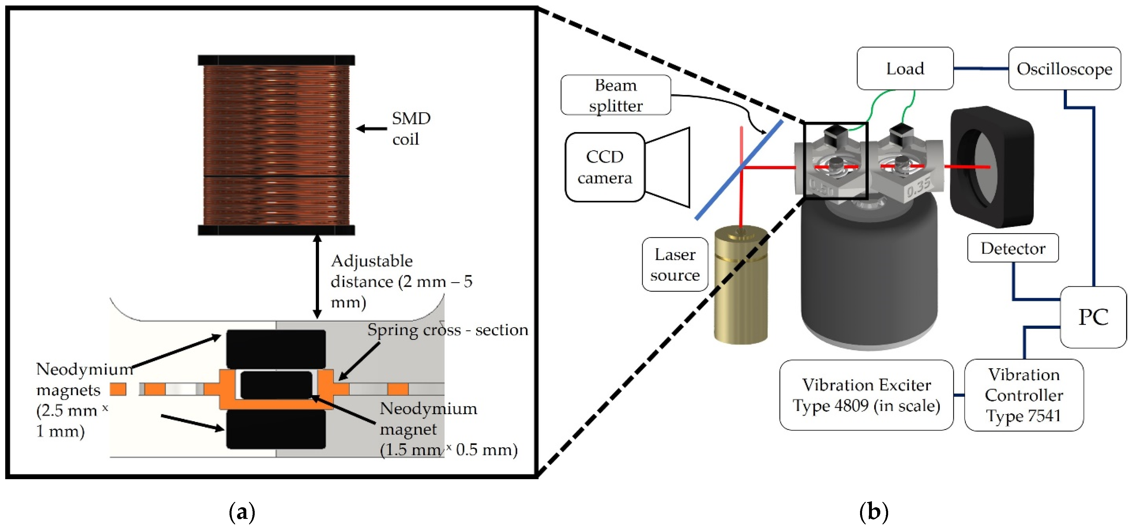
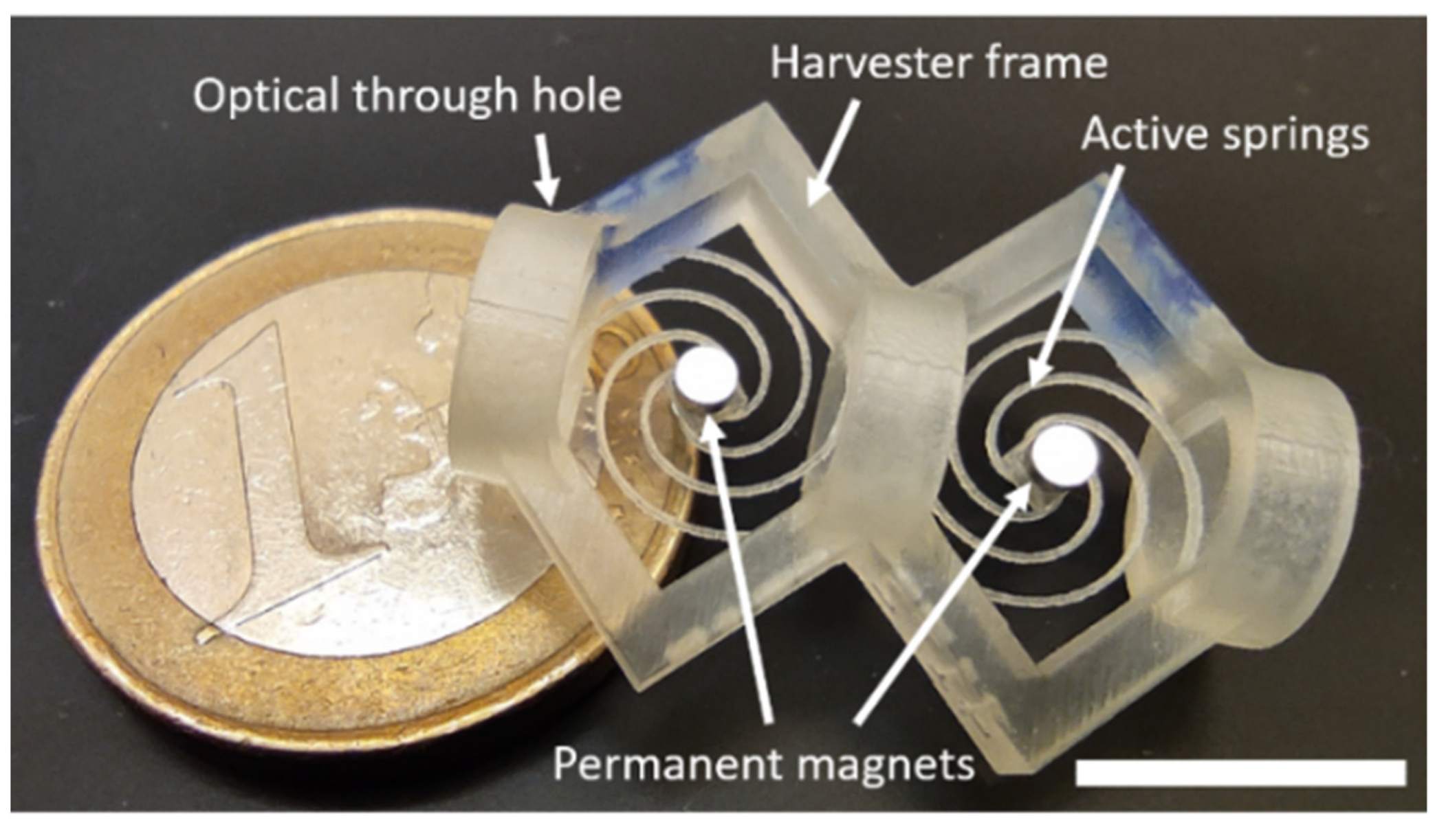
2.2. Harvester Assembly and Measurement Setup
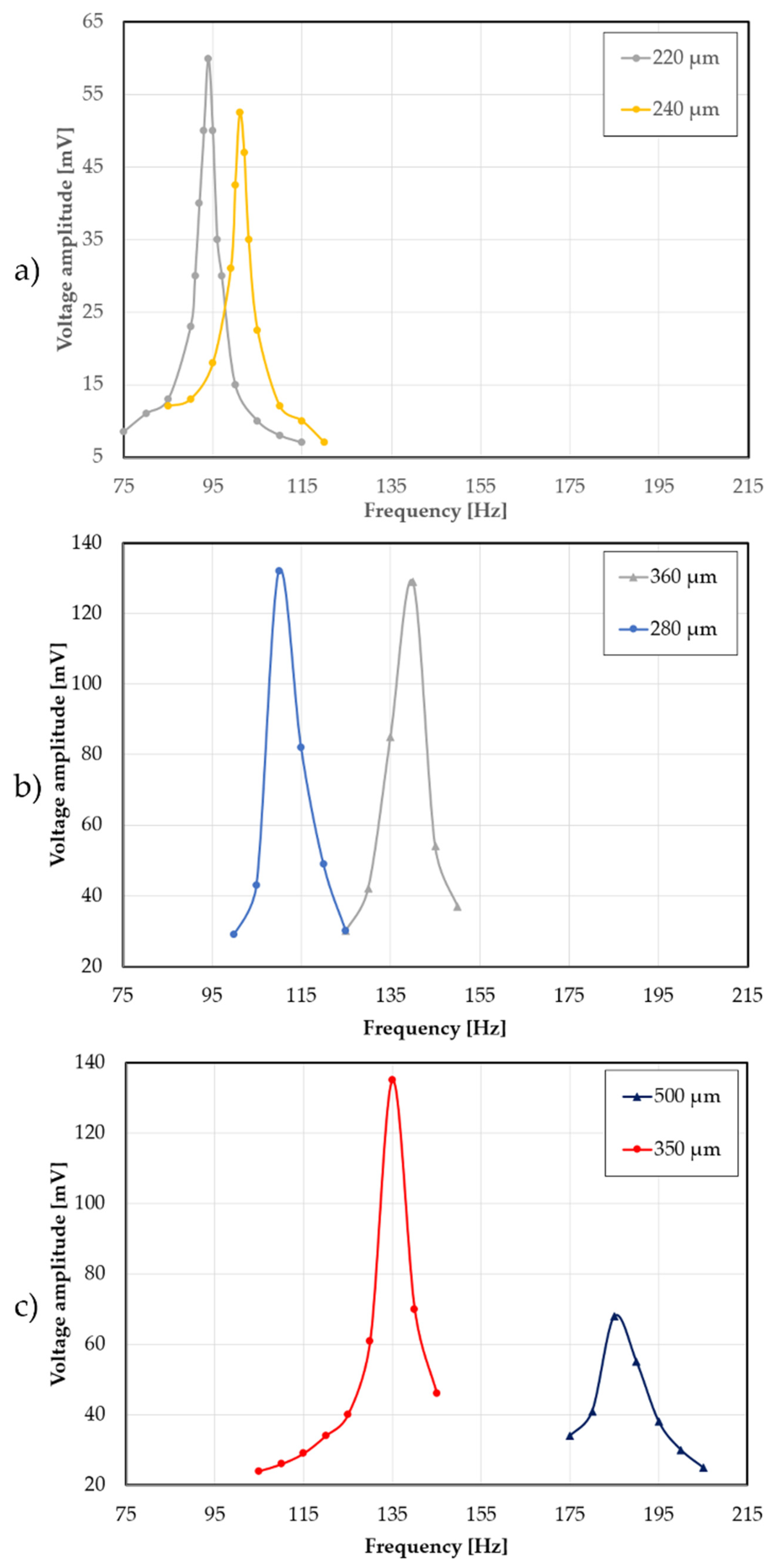
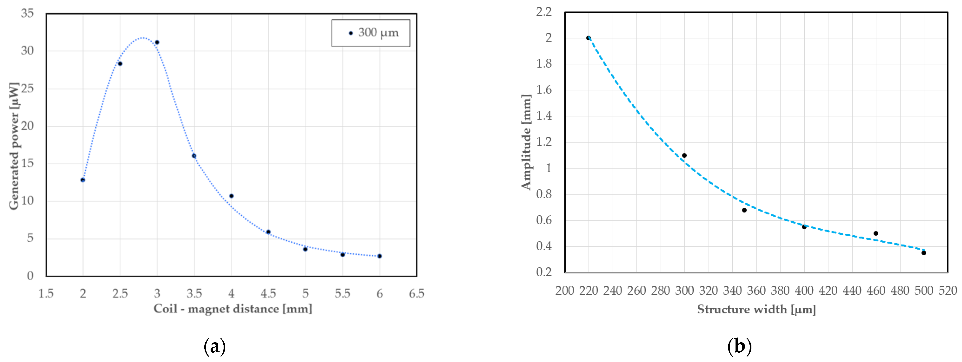
The printed harvester microstructures were assembled with commercially available magnets and SMD coils. The proof mass was formed with one small magnet in the center (Ø = 1 mm, 0.5 mm thick) and two bigger magnets (Ø = 1 mm, 2.5-mm-thick) at the top and bottom of the small one (Figure 2). The weight of all three magnets was 55.5 mg. The SMD coils (type 812) with measured 6.56 mH inductance and 202 Ω resistance were placed in a printed holder with adjustable (2–5 mm) distance in relation to the magnets (Figure 2).
The scheme of the measurement setup is presented in Figure 2b. A type 4809 portable vibration exciter generating a vibration frequency range from 10 Hz to 20 kHz (Brüel & Kjær, Nærum, Denmark) with a set constant acceleration (1 g) co-working with a vibration controller type 2718 and a power amplifier type 2718 were applied as a controlled vibration source. The vibrating microstructure was observed by a camera (HDCE-X2, 2 MP, Sony, Tokyo, Japan) through the window in the printed structure. The camera collected images with 30 fps, and it was used to estimate amplitude of the vibrating microstructure and distance between magnets and coils [27]. Both vibrating microstructures were illuminated with a collimated laser light (635 nm, 5 mW). The modulated laser light (frequency of modulation was equal to the frequency of vibrations) was detected by a photodetector (OPT101, Thorlabs, Newton, NJ, USA). Electric signals from the coils were recorded by a digital oscilloscope (DSO5102B, Hantek, QingDao, China). Output of the coils was connected to a variable (10–1300 Ω) resistance loading. The printed energy harvester structures were suspended 8 cm over the vibration exciter top level. This ensured that the electromagnetic field from the exciter will not influence on the electromotive force induced in the coil over the structure. Both signals—optical and electrical—were used to determine resonant frequency of the microstructures.

3. Results

A view of the printed energy harvesters with two microstructures with assembled neodymium magnets is shown in Figure 3.
Simulated and experimentally measured dependence of microstructure resonant frequency on the spring width is shown in Figure 4. The results of simulations and measurements were similar. The biggest mismatch (around 20 Hz) was noticed for narrow springs (width below 250 µm at the limits of the printer resolution and accuracy), results for wider springs were more convergent. The measured dependence was linear. Taking into account limited resolution of the printer (750 dpi), one dot per inch corresponded to 33.8 µm error in printing resolution. Thus, all measured resonant frequencies were within “±1 dpi tunnel” caused by limited printer resolution. Additionally, percentage errors for measured frequencies depending on the simulations were calculated (Table 2) and showed that the mean percentage error is equal to 2.9%.
On the basis of linear dependence and the determined equation (Figure 4) involving structure width and resonant frequency, it was possible to design an energy harvester with two vibrating microstructures with required resonant frequencies. For example, the harvester working with two resonant frequencies 110 and 140 Hz should have springs with 280 and 360 µm widths, respectively. Exemplary output characteristics (amplitude of generated voltage as a function of vibration frequencies near the resonant ones) are shown in Figure 5. It was possible to design, print, and characterize microstructures with resonant frequency differences from Δf = 10 Hz (for springs with width equal to 220 and 240 µm) to Δf = 95 Hz (for springs with widths equal to 220 and 500 µm). Taking into account characteristics presented in Figure 4, the theoretical difference in resonant frequency of the microstructure caused by limited printing resolution was 16.9 Hz (change of 1 dpi corresponded to 33.8 µm). Experimentally obtained minimal planar resolution (repeatable) was slightly better (±18 µm) [28] what corresponds to around 10 Hz minimal difference in resonant frequencies between two springs with 20 µm difference in width. It was in good relation to the experimentally obtained minimal frequency difference (Figure 5a). In this case, the coil–magnet distance was the same for all structures and was equal to 3 mm. The differences in amplitude of generated open-circuit voltage at resonant frequencies in Figure 5 are caused by different structure vibration amplitudes.
The influence of the distance between coil and the proof mass (magnets) on output power was also investigated. An exemplary characteristic for a 300 μm width spring is shown in Figure 6a. The gap was changed from 2 to 5 mm. It was found that the optimal distance was in the 2.8–3 mm range. The amplitude of the spring movement (300 μm width) at resonant frequency was 1.1 mm and it was determined on the basis of optical measurements (image analysis) also for other spring widths (Figure 6b). It was concluded that optimal coil–magnet distance was about 2.5 times the amplitude of proof mass–spring vibrations.
The power versus loading resistance for fixed magnet–coil distance characteristics showed optimal operation of the harvesters at around 350 Ω (Figure 7). The output power for a single microstructure at a resonant frequency was in the 6–21 μW range. Maximal summary power from two independent coils (300 and 400 μm tandem) was 32 μW. In comparison to single frequency harvesters presented previously by us these values were comparable. The obtained power density was 227 μW/cm3. It was slightly smaller than for single frequency devices, but multi-frequency operation was achieved instead.

4. Discussion

The presented performance of the multi-frequency energy harvester can be matched with examples from the literature, especially those based on an electromagnetic transducer type (Table 3). The energy density is comparable to the other solutions but can be increased by implementing shape optimization and introducing harvester-load resonant frequency matching [29,30,31]. The main advantage of this solution is small size and the ability to work in multi-frequency modes as designed based on the simulations.
Regarding the resonant frequency simulation fitting, the key factors for increasing the accuracy are: minimum mesh element size and proper Young’s modulus value.
The simulation parameters had to be selected locally so that the minimum mesh element was significantly smaller than the width of the spring, which was at least 220 µm. It was found that a mesh element smaller than 0.05 mm did not significantly change the accuracy of the simulation. Therefore, the obtained accuracy fits well in this case and the error of measured frequencies depending on the simulation is below 5% for 80% of the measured structures. Additionally, the Young’s modulus value in the case of thin structures may also differ as presented in [16,27]. Therefore, averaging was chosen for simulation purposes and the value of 2.224 GPa was used, which has been shown to cover most of the measured frequency values, giving the ability to design the harvester structure work under the specific frequency required. Nevertheless, a larger frequency range will require additional studies of the mechanical properties and a precise determination of the Young’s modulus.

5. Summary and Conclusions

The multi-frequency electromagnetic energy harvesters are interesting and still under development solutions co-working with mechanical devices vibrating with various frequencies. In this paper, we presented for the first time 3D printed energy harvesters with two independent vibrating transducers working with two resonant frequencies. The principle of operation of the devices was based on two microstructures with springs with constant thickness (300 µm) and tailored widths from 250 to 500 µm. The resonant frequency of the microstructure could be designed and changed in the 85–185 Hz range by spring width adjustment. The numerical simulations and measurements of the resonant frequencies were in good agreement and described by linear equations. Thus, it was possible to design the vibration microstructures to desired frequencies with minimal accuracy and distance between the resonance peaks around 10 Hz. The maximal output power (32.7 µW) was obtained for 350 Ω loading resistance for devices with 300 and 400 µm width springs and 112 Hz/153 Hz resonant frequencies. It corresponded to 227 µW/cm3 power density. Thanks to flexibility of 3DP, it is possible to design and print more than two vibrating microstructures towards development of the miniature energy harvester with three or more operation resonant frequencies to increase efficiency of energy transduction from mechanical vibration.

Author Contributions

Conceptualization and supervision R.W.; methodology, design, printing, and measurements, software for electrical characterization B.K.; numerical simulations and validation C.L. All authors have read and agreed to the published version of the manuscript.

Funding

The works were realized under NAWA “Academic International Partnerships of Wroclaw University of Science and Technology” program by the Polish National Agency for Academic Exchange Program (www.nava.gov.pl, accessed on 29 April 2022) and National Research Centre (project no. 2019/35/B/ST8/00687).

Institutional Review Board Statement

Not applicable.

Informed Consent Statement

Not applicable.

Data Availability Statement

Not applicable.

Conflicts of Interest

The authors declare no conflict of interest.

References

  1. Iqbal, M.; Nauman, M.; Khan, F.; Abas, P.; Cheok, Q.; Iqbal, A.; Aissa, B. Vibration-based piezoelectric, electromagnetic, and hybrid energy harvesters for microsystems applications: A contributed review. Int. J. Energy Res. 2021, 45, 65–102. [Google Scholar] [CrossRef]
  2. Landaluce, H.; Arjona, L.; Perallos, A.; Falcone, F.; Angulo, I.; Muralter, F. A Review of IoT Sensing Applications and Challenges Using RFID and Wireless Sensor Networks. Sensors 2020, 20, 2495. [Google Scholar] [CrossRef] [PubMed]
  3. Bryzek, J. Trillion Sensors Movement in Support of Abundance and Internet of Everything. In Proceedings of the Materials of Sensors Conference, Santa Clara, CA, USA, 6 March 2014. [Google Scholar]
  4. Mohanty, A.; Parida, S.; Behera, R.; Tarapada, R. Vibration Energy harvesting: A review. J. Adv. Dielectr. 2019, 9, 1930001. [Google Scholar] [CrossRef]
  5. Kim, Y.; Keun, H. Elastic Member and Vibration Absorption Apparatus for a Refrigerator Compressor. U.S. Patent 6,912,865, 5 July 2005. [Google Scholar]
  6. Yang, B.; Lee, C.; Xiang, W.; Xie, J.; He, J.; Kotlanka, R.; Low, S.; Feng, H. Electromagnetic Energy harvesting from vibrations of multiple frequencies. J. Micromech. Microeng. 2009, 19, 035001. [Google Scholar] [CrossRef]
  7. Liu, H.; Qian, Y.; Lee, C. A multi-frequency vibration-based MEMS electromagnetic energy harvesting device. Sens. Actuators Phys. 2013, 204, 37–43. [Google Scholar] [CrossRef]
  8. Chen, J.; Chen, D.; Yuan, T.; Chen, X. A multi-frequency sandwich type electromagnetic vibration energy harvester. Appl. Phys. Lett. 2012, 100, 213509. [Google Scholar] [CrossRef]
  9. Foisal, A.; Hong, C.; Chung, G. Multi-frequency electromagnetic energy harvester using a magnetic spring cantilever. Sens. Actuators Phys. 2012, 182, 106–113. [Google Scholar] [CrossRef]
  10. Deng, H.; Du, Y.; Wang, Z.; Zhang, J.; Ma, M.; Zhong, X. A multimodal and multidirectional vibrational energy harvester using a double-branched beam. Appl. Phys. Lett. 2018, 112, 213901. [Google Scholar] [CrossRef]
  11. Liu, D.; Haisheng, L.; Feng, H.; Yalkun, T.; Hajj, M. A multi-frequency piezoelectric vibration energy harvester with liquid filled container as the proof mass. Appl. Phys. Lett. 2019, 114, 213902. [Google Scholar] [CrossRef]
  12. Mazeika, D.; Ceponis, A.; Yang, Y. Multifrequency piezoelectric energy harvester based on poligon-shaped Cantilever array. Shock. Vib. 2018, 2018, 5037187. [Google Scholar]
  13. Shin, Y.H.; Choi, J.; Kim, S.J.; Kim, S.; Maurya, D.; Sung, T.H.; Song, H.C. Automatic resonance tuning mechanism for ultrawide bandwidth mechanical energy harvesting. Nano Energy 2020, 77, 104986. [Google Scholar] [CrossRef]
  14. Wang, Z.; Du, Y.; Li, T.; Yan, Z.; Tan, T. A flute-inspired broadband piezoelectric vibration energy harvesting device with mechanical intelligent design. Appl. Energy 2021, 303, 117577. [Google Scholar] [CrossRef]
  15. Walczak, R.; Adamski, K.; Lizanets, D. Inkjet 3D printed check microvalve. J. Micromech. Microeng. 2017, 27, 047002. [Google Scholar] [CrossRef]
  16. Walczak, R.; Kawa, B.; Adamski, K. Inkjet 3D printed microfluidic device for growing seed root and stalk mechanical characterization. Sens. Actuators Phys. 2019, 297, 111557. [Google Scholar] [CrossRef]
  17. Walczak, R. Inkjet 3D printing–towards new micromachining tool for MEMS fabrication. Bull. Polish Acad. Sci. Tech. Sci. 2018, 66, 179–186. [Google Scholar]
  18. Ju, S.; Ji, C.-H. Impact-based piezoelectric vibration energy harvester. Appl. Energy 2018, 214, 139–151. [Google Scholar] [CrossRef]
  19. Maharjan, P.; Cho, H.; Rasel, M.; Salauddin, M.; Park, J.Y. A fully enclosed, 3D printed, hybridized nanogenerator with flexible flux concentrator for harvesting diverse human biomechanical energy. Nano Energy 2018, 53, 213–224. [Google Scholar] [CrossRef]
  20. Seol, M.-L.; Ivaskeviciute-Povilauskiene, R.; Ciappesoni, M.A.; Thompson, F.V.; Moon, D.-I.; Kim, S.J.; Han, J.-W.; Meyyappan, M.; Kim, S.J. All 3D printed energy harvester for autonomous and sustainable resource utilization. Nano Energy 2018, 52, 271–278. [Google Scholar] [CrossRef]
  21. Seol, M.-L.; Han, J.-W.; Moon, D.-I.; Yoon, K.J.; Hwang, C.S.; Meyyappan, M. All-printed triboelectric nanogenerator. Nano Energy 2018, 44, 82–88. [Google Scholar] [CrossRef]
  22. Hadas, Z.; Zouhar, J.; Singule, V.; Ondrusek, C. Design of energy harvesting generator base on rapid prototyping parts. In Proceedings of the 2008 13th International Power Electronics and Motion Control Conference, Poznan, Poland, 1–3 September 2008; pp. 1665–1669. [Google Scholar]
  23. Rubes, O.; Smilek, J.; Hadas, Z. Development of vibration energy harvester fabricated by rapid prototyping technology. In Proceedings of the 16th International Conference on Mechatronics—Mechatronika 2014, Brno, Czech Republic, 3–5 December 2014; pp. 178–182. [Google Scholar]
  24. Bowers, B.; Arnold, D. Spherical magnetic generator for bio-motional energy harvesting. In Proceedings of the PowerMEMS 2008 Conference, Sendai, Japan, 9–12 November 2008; pp. 281–284. [Google Scholar]
  25. Constantinou, P.; Roy, S. A 3D printed electromagnetic nonlinear vibration energy harvester. Smart Mater. Struct. 2016, 25, 95053. [Google Scholar] [CrossRef] [Green Version]
  26. Gawron, P.; Wendt, T.M.; Stiglmeier, L.; Hangst, N.; Himmelsbach, U.B. A review on kinetic energy harvesting with focus on 3D printed electromagnetic vibration harvesters. Energies 2021, 14, 6961. [Google Scholar] [CrossRef]
  27. Kawa, B.; Śliwa, K.; Lee, C.; Shi, Q.; Walczak, R. Inkjet 3D printed MEMS vibrational electromagnetic energy harvester. Energies 2020, 13, 2800. [Google Scholar] [CrossRef]
  28. Walczak, R.; Adamski, K. Inkjet 3D printing of microfluidic structures—on the selection of the printer towards printing your own microfluidic chips. J. Micromech. Microeng. 2015, 26, 085013. [Google Scholar] [CrossRef]
  29. Yan, Z.; Sun, W.; Hajj, M.R.; Zhang, W.; Tan, T. Ultra-broadband piezoelectric energy harvesting via bistable multi-hardening and multi-softening. Nonlinear Dyn. 2020, 100, 1057–1077. [Google Scholar] [CrossRef]
  30. Yu, T.; Zhou, S. Performance investigations of nonlinear piezoelectric energy harvesters with a resonant circuit under white Gaussian noises. Nonlinear Dyn. 2021, 103, 183–196. [Google Scholar] [CrossRef]
  31. Bonnin, M.; Traversa, F.L.; Bonani, F. An Impedance Matching Solution to Increase the Harvested Power and Efficiency of Nonlinear Piezoelectric Energy Harvesters. Energies 2022, 15, 2764. [Google Scholar] [CrossRef]
  32. Kimionis, J.; Isakov, M.; Georgiadis, A.; Koh, B.S.; Tentzeris, M.M. 3D-Printed Origami Packaging with Inkjet-Printed Antennas for RF Harvesting Sensors. IEEE Trans. Microw. Theory Tech. 2015, 63, 4521–4532. [Google Scholar] [CrossRef] [Green Version]
  33. Nammari, A.; Caskey, L.; Negrete, J.; Bardaweel, H. Fabrication and characterization of non-resonant magneto-mechanical low-frequency vibration energy harvester. Mech. Syst. Signal Process. 2018, 102, 298–311. [Google Scholar] [CrossRef]
Figure 1. Computer visualization of the harvester with two independent vibrating structures with magnets (scale bar 10 mm).
Energies 15 04468 g001
Figure 2. Multi-frequency 3DP energy harvester: (a) cross-section of the proof mass of the harvester with assembled neodymium magnets, (b) scheme of the measurement set up.
Energies 15 04468 g002
Figure 3. Printed and assembled structure (EUR 1 coin for comparison), scale bar 10 mm.
Energies 15 04468 g003
Figure 4. Resonant frequency (F) versus spring width (Wh) - results of simulation and measurements with upper and lower frequency “tunnel” resulting from the printer resolution error, determined linear equations Fmeasured = f(Wh) and Fsimulated = f(Wh) with coefficients of determination (R-Squared) are also shown.
Energies 15 04468 g004
Figure 5. Amplitudes of the generated open-circuit voltage at resonant frequencies for tandem microstructures of the harvesters: (a) spring widths 220 and 240 μm, (b) spring widths 280 and 360 μm, (c) spring widths 350 and 500 μm.
Energies 15 04468 g005
Figure 6. The 3D printed vibrational energy harvester: (a) output generated power (loading resistance 350 Ω) as a function of coil–magnets distance for a 300 μm width spring, (b) amplitude of microstructure vibrations at resonant frequency as a function of spring width.
Energies 15 04468 g006
Figure 7. Output generated power as a function of loading resistance for two tandem microstructures with spring widths: (a) 300 and 400 μm, (b) 350 and 500 μm.
Energies 15 04468 g007
Table 1. Main parameters of examples of the multi-frequency electromagnetic and piezoelectric energy harvesters.
TransductionResonant Frequencies [Hz] or Band Width [Hz]Maximal Output Power P [μW] or Power Density PD [μW/cm3]Characteristic DimensionsFabrication TechnologyRef.
Electromagnetic369, 938 and 1184P = 3.2Length of acrylic beam 54 mm; width of single-layer coil area 10 mm.PCB, laser machining[6]
840, 1070 and 1490PD = 0.1257MEMS chip 10 × 8 × 2.5 mm3; cylindrical magnet radius 1.5 mm, 2 mm high; center circular mass outer radius 2.5 mm; thickness of the circular rings 100–350 μm.MEMS[7]
235, 330 and 430 P = 10Platform outer dimension 4 × 4 × 2 mm3, spring thickness 30 μmMEMS[8]
7.32, 8.67, 8.92, 10.48PD = 52.02Magnets size from 6 × 12 to 6 × 16 mm2, total volume of the harvesters from 40.18 to 108 cm3.Traditional machining [9]
Piezoelectric3–25PD = 1.76PVDF film dimension 30 × 12 mm2, thickness 28 μm; length of primary cantilever beam 100 mm; length of each branch 86.8 mmTraditional machining[10]
14.4/15.2, 11.5/12.4, 14.5/15.6, 12/12.8P = 1000PZT patch 55 mm long, 20 mm wide, 0.2 mm thick; substrate beam 150 mm long, 20 mm wide, 1 mm thick; water container diameter 46 mm, depth 22 mm.Traditional machining[11]
14.5, 26.1, 74.2, 199.5, 215.3P = 65.24Length of polygon arms from 2 to 23 mm, width 5 mm.Metal and PZT machining[12]
Table 2. Percentage discrepancy in the actual frequency value in relation to the simulation for individual spring widths.
Spring width [µm]220240260280300320340360380400420440460480500
Percentage error [%]3.50.41.91.12.83.90.91.72.50.50.55.73.47.86.9
Table 3. Comparison of the presented energy harvester printed solution to examples from the literature on the subject.
Transducer TypeDimensionsGenerated VoltageEnergy DensityMulti-FrequencyRef.
Radio frequency5.7 × 5.7 × 5.7 cm150 mVNo data.No[32]
Piezoelectric26 × 10 × 10 mm35 V0.3 mW/cm3No[18]
TriboelectricDisc with a diameter of a dozen cm and a thickness of a few mm230 V4.52 mW/cm3No[20]
Electromagnetic45 × 55 × 40 mm9 V1.28 mW/cm3No[23]
80 × 40 mm3 V0.133 mW/cm3No[33]
20 × 10 × 6 mm140 mV0.227 mW/cm3YesThis work
Publisher’s Note: MDPI stays neutral with regard to jurisdictional claims in published maps and institutional affiliations.

