Article

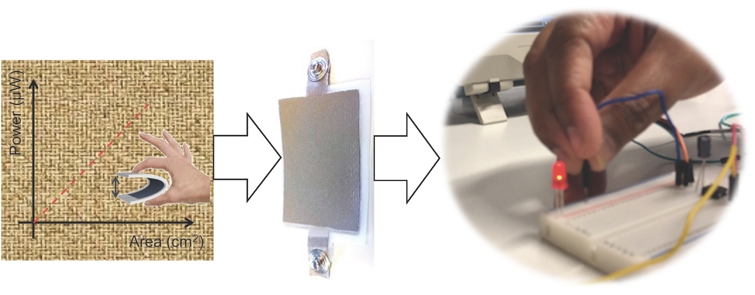
A Piezoelectric Smart Textile for Energy Harvesting and Wearable Self-Powered Sensors

by
Ishtia Zahir Hossain
,
Ashaduzzaman Khan
and
Gaffar Hossain
*
V-Trion Textile Research GmbH, Schwefelbadstrasse 2a, 6845 Hohenems, Austria
*
Author to whom correspondence should be addressed.
Energies 2022, 15(15), 5541; https://doi.org/10.3390/en15155541
Submission received: 8 June 2022 / Revised: 22 July 2022 / Accepted: 25 July 2022 / Published: 30 July 2022
(This article belongs to the Special Issue Vibration-Based Energy Harvesters)

Abstract

:
Today’s wearable electronics have dramatically altered our daily lives and created an urgent demand for new and intelligent sensor technologies. As a new energy source, self-powering sensors are currently seen as critically important units for wearable and non-wearable textile–electronic systems. To this aim, this paper presents a smart textile-based piezoelectric energy-autonomous harvester and a self-powered sensor for wearable application, where the sandwich structure of the wearable sensor consists of top and bottom textile conductors, and in between the two textile electrodes there is a piezoelectric PVDF thin film. The generating voltage, current, charge, power, and capacitor charging–discharging behaviour of the device were confirmed using multimeter, oscilloscope, Keithley, etc., analyses. Finally, a piezoelectric-textile sensor was integrated into wearable clothes for breathing detection; a shoe insole for footstep recognition; and it can store energy by tapping, to power electronics, such as a calculator, timer, LED, etc., at a later time. The sensitivity of the sensor was enough for generating voltage from a tiny water droplet. Thus, we can assume raindrops to be utilized as a power-generating source on days when no sun is available to solar cells.

Graphical Abstract

1. Introduction

In the era of the Internet of Things (IoT), modern wearable electronic devices and their communication networks are marching into every corner of modern society and changing every aspect of our daily life. Thus, the progress of digitalization, including miniaturization of wearable sensing technology, and its growing importance to physical and psychological well-being, have a tremendous impact on almost all consumer goods from the wearable to non-wearable industries [1]. As we all know, textiles and fibres are regarded as the second human skin and have been widely used by humans for thousands of years, due to its unique features and excellent performance, e.g., stretching, twisting, bending, and tearing, which exhibit the outstanding ability of structural retention and fatigue resistance during wearing, where fibres and fabric-based flexible electronics play important roles, particularly in the areas of biomedical and health monitoring [2,3,4], implants and prosthesis, motion tracking, artificial intelligence, and human–computer interaction, etc. [1,5,6]. Simultaneously, there have been significant research effort in powering such sensors. However, most wearable sensors observed today are powered by external lithium-based batteries, which are heavy, not flexible, not washable, and not breathable [7,8].
Some of those are self-sufficient, frequently called self-powered sensors and other names. Many forms of energy sources can be collected and converted, such as mechanical energy (e.g., motion or movement or vibration), solar energy, thermal energy, wind energy, thermoelectric energy, electrochemical energy, etc. [9,10]. Among those energy sources, mechanical and thermoelectric energy harvesting can be readily integrated with wearable or stretchable electronic systems, as they are usually attached to objects that will deform, bend, stretch, and act as a heat source (e.g., human organs or skin) [9]. For instance, movements, vibrations, or motions of an object available around us can be conveniently converted into electrical energy by piezoelectric generators, tribe electric generators, or dielectric elastomers. Along with the boom of flexible electronics, various mechanical energy harvesters as well as wearable energy sources have been demonstrated [11,12,13]. Harvesting energy from the ambient environment to power these wireless monitoring systems could be a key technology for the development of self-powered systems since it allows the extraction of energy from different sources with no cost and avoiding the use of dedicated power lines [11,14,15]. Fortunately, there are some energy-harvesting technologies available right now, for example, solar, wind, tide energy, etc., which are targeted to produce mega to giga-watt power [16,17,18,19]. However, energy production and self-powered sensors associated with human functions and activities are yet to be seen in laboratory research [14]. Most of the wasted energy associated with human mechanical energy is because of body motion such as walking, running, hiking, talking, breathing, etc., all of which can be easily converted into electrical energy to sense and provide the necessary power to recognize the physiological activities of humans [20]. Piezoelectric and triboelectric energy sources that utilized human motion recently have been investigated as the most self-powered wearables. Piezoelectricity is a property found in some materials when these materials are pressed or compressed, subsequently creating some electric charge that accumulates in the material [21]. When reversed, an outer electrical field either stretches or compresses the piezoelectric material [22,23] (Figure 1). Because of such extraordinary features, recently piezoelectric micro-and nanostructures materials have attracted extensive attention because they can provide a practical way to scavenge mechanical energy from the environment [24]. However, some early systematic studies have discovered over 200 piezoelectric materials, such as zirconate titanate (PZT), zinc oxide (ZnO), barium titanate (BaTiO3), gallium orthophosphate (GaPO4), potassium niobate (KNbO3), lead titanate (PbTiO3), lithiul tantalate (LiTaO3), langasite (La3Ga5SiO14), sodium tungstate (Na2WO3), and PVDF [20,25].
Among the other piezoelectric materials, PVDF has a relatively large piezoelectric and pyroelectric response, which makes it suitable for exploitation in the development of flexible electronic devices [24,26]. PVDF also has an advantage over other materials due to its high mechanical properties, chemical resistance, and good thermal stability, as well as easy fabrication process. Hence, PVDF has been considered the preferred candidate for lightweight piezoelectric sensors with curved surfaces, and for tiny, complex, and flexible structures [6,22,26,27]. For instance, piezoresistive PVDF foils are frequently used as a thin, active electromechanical transducer, which are able to transduce approximately 12% of the mechanical energy to electrical energy, and inversely [21]. A wearable energy harvester generating electric power from heel strikes and strain applied on a backpack strap during walking produced a maximum power of 45.6 mW; as a similar concept, using the knee-joint of a human body, demonstrated by another author, a peak power output of 1.1 mW was achieved, with the PVDF fibres in woven textiles [21,24].
In this study, we designed and fabricated a flexible PVDF (polyvinylidene fluoride) piezoelectric smart-textile sensor (PSTS) and harvester (PSTH) using a piezoelectric conversion mechanism. When the PVDF piezoelectric-textile sensor is pressurised, vibrated, or deformed, an AC voltage is generated that can be used to detect pressure, vibration, or movement for health monitoring. This AC signal can be converted into a DC signal with a rectifier circuit and the charge generated by the sensors can be stored on a storing device (capacitor, battery), etc. Our fabricated 24 cm2 PVDF piezoelectric-smart textile harvester (PSTH) [28] stored energy about 6 μW, generated a current of 2.36 μA, and had a 22.4 nC charge against a 1.5 MΩ resistive load applying a rectifier circuit. The PSTH was able to lighten about up to 32 LEDS, vibrating the sensor by hand for about 20 s without storing it to the capacitor. Depending on the application, where more power or current is needed, multiple PSTHs can be connected side by side or layer by layer in series or in parallel, applying a different resistive load. The effectiveness and sensitivity of the sensor were demonstrated by the recognition of a tiny water droplets of less than 50 mg weight, footstep detection by walking, and breathing detection, etc., which makes the PSTS suitable for both power generation and a self-powered sensor for health monitoring application. The major innovation aspect of this research is the simplicity of the manufacturing process (as patented US20220123197A1 by the author Hossain et al.) of the textile-based piezoelectric energy harvester, which is very thin, flexible, and comfortable to wear, and can be easily integrated into human wearables or any movable, rotating, or vibrating device to detect their vibration or movement and simultaneously generate energy from these motions.

2. Experimental

2.1. Materials

A commercial β-phase polyvinylidenefluoride (PVDF) film was purchased from Kureha Corporation, Nihonbashi-Hamacho, Japan. There were two types of piezoelectric films with a thickness of 28 μm and the piezoelectric constant of d31 (pC/N) was 25; among them one was previously polarized and the other had a deposition of aluminium (Al) on polarized PVDF film. A polyester woven fabric coated with silver has been obtained from the commercial sources. Textiles as supporting materials, such as woven and knitted polyester fabrics, were provided by the company Grabher Group, Lustenau, Austria. The standard argon and oxygen gases with purity (>99.9%) were purchased from Air Liquid to functionalize the polyester fabrics applying plasma treatment to improve the lamination behaviour. Commercially available conductive thread (stainless-steel coated onto polyester yarn with a thickness of 0.3 mm and resistivity of 115 Ω m−1) and a nonconductive polyester thread (bobbin thread) were used to produce textile electrodes by stitching onto a polyester fine fabric (~20 g/cm2) support using a Oerlikon Saurer shuttle embroidery machine. All other electronic tools, including an oscilloscope, Keithley, Fluke digital multimeter, and components for electronics, were used for the characterization from a standard smart-textile electro laboratory at V-Trion.

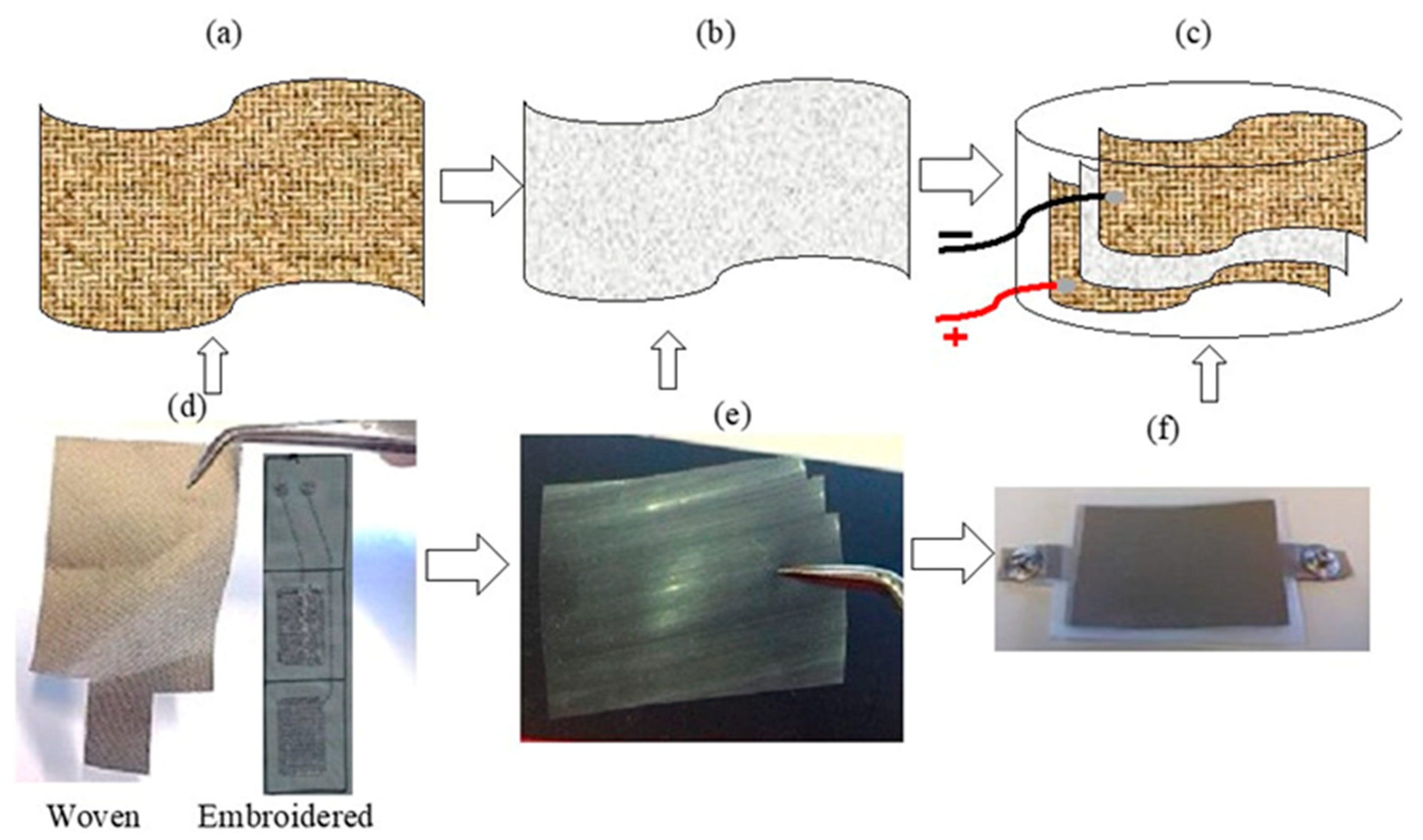
2.2. Smart-Textile Current Collector for a Piezoelectric Smart-Textile Sensor (PSTS) and Harvester (PSTH)

Computer-aided design (CAD) has been used to make the design PSTS and PSTH based on the application. The program was transmitted to the embroidery machine in order to copy the exact rectangular matrices with a rectangular pattern by stitching with a needle thread and bobbin thread. Stainless-steel yarn was used to stitch directly onto the supporting materials, such as woven polyester and elastic belts, for the connection with the electronics. Where the face side with conductive surface was obtained when using the conductive yarn as the needle thread and the back with non-conductive paths of polyester yarns as the bobbin thread. Thus, the top and bottom textile electrode materials were obtained with a rectangular pattern electrode surface for both sensor and harvester.

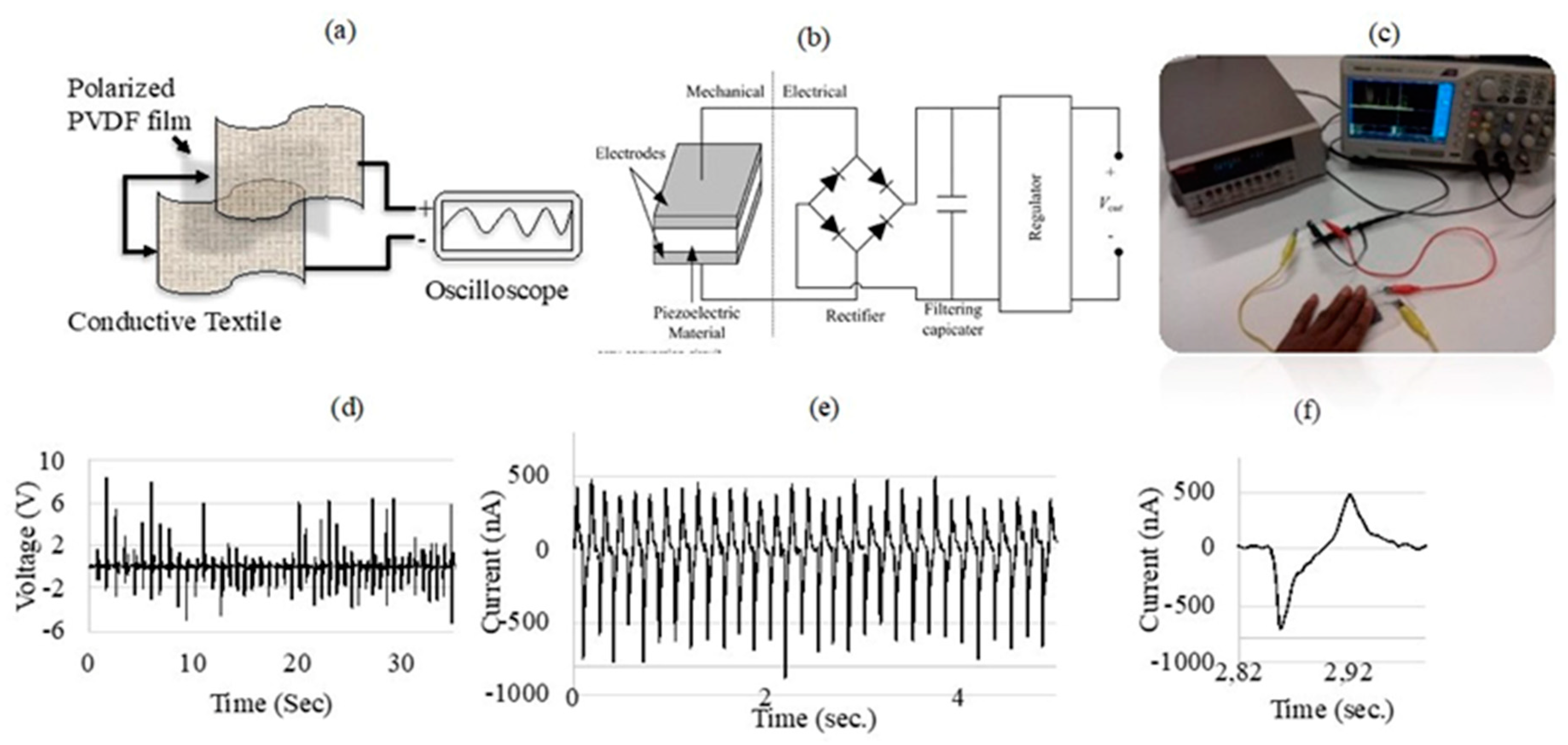
2.3. Fabrication of the Piezoelectric Smart-Textile Sensor (PSTS) and Harvester (PSTH)

The PSTS and PSTH were manufactured as a sandwich structure composed of a conductive textile as the top and bottom layers adjacent to an intermediate layer with a polarized PVDF film (Figure 2b,e), where the conductive textile work as electrodes to collect the stress-induced charges from the piezoelectric film. The conductive material was used to covered both sides of the PVDF film, as can be seen in Figure 2a–c. The fabrication process of the PSTS and PSTH, as defined in Step 1, is where the conductive textiles, as woven or embroidered electrodes Figure 2a,d, namely, the top and bottom electrically conductive layers, are prepared. For this purpose, conductive surfaces, such as a silver-coated woven textile (Ag) and stainless-steel embroidery knitted structure, were used. The next step, Step 2, of the method is the activation of the piezoelectric polymer film layer with plasma, as explained above. This is mainly done to increase the adhesion of the film into a conductive textile as the next step. In Step 3, the PSTS and PSTH devices are completed by laminating (at 90 °C for 15 s) with an outer protective polyurethane (PU) film (Gerlinger, Netzschkau, Germany) layer, making the PSTS and PSTH in the sandwich form.
The conductive textile and protective PU makes the PSTS and PSTH soft and flexible, stretchable, wearable, durable, and washable, thanks to the washable PU film. In the last step, Step 4, several energy conversion techniques were developed to convert the mechanical energy from movement, vibration, or pressure into electrical energy. For the purpose of converting the AC voltages generated by the PSTH into DC voltages, a rectifying circuit was integrated into the device. In this last step of the production of the device, storing of the energy also takes place, generated by the vibration of or movement by the PSTH. Finally, the connecting points of both sides of the electrodes were attached to the silver-coated press button and integrated into the wearables as self-powered sensors, e.g., a sensor belt for breathing detection, shoe insole for body activity recognition, touch sensor, etc., and energy harvesting for lighting an LED.

3. Result and Discussion

PVDF film is a kind of piezoelectric polymer, which is very sensitive to the change in the strain applied to it. The piezoelectric-textile sensor (PSTS) device generates voltage and current, as can be observed in Figure 3d–f, when it is deformed or pressurized externally. That is assumed to be due to the potential difference: the piezoelectric potential-driven electrons flow from one electrode to the other. On the other hand, the piezoelectric potential disappears upon releasing mechanical force from the PSTS device and stored electrons will flow via external circuit in reverse direction to the other electrode, which results in an electric signal in the opposite direction. Thus, a simple PSTS circuit was built with the energy harvesting power conversion circuits, as depicted in Figure 3a–c. A direct AC-to-DC converter is shown Figure 3b,c. The converter consists of a rectifier and capacitor. The output result appears in the short-circuit current (Figure 3e,f) while vibrating the PSTS sensor by hand.

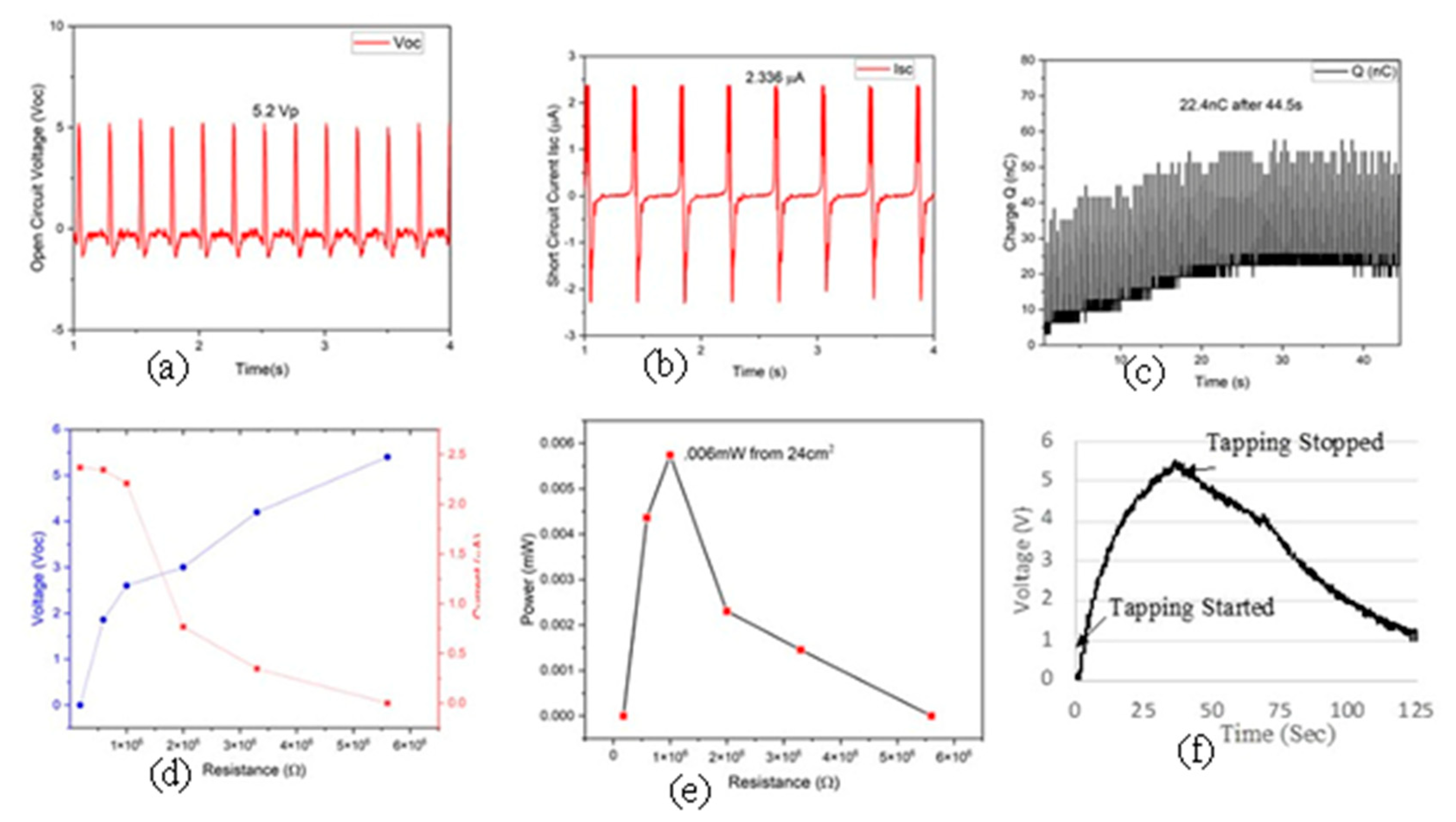
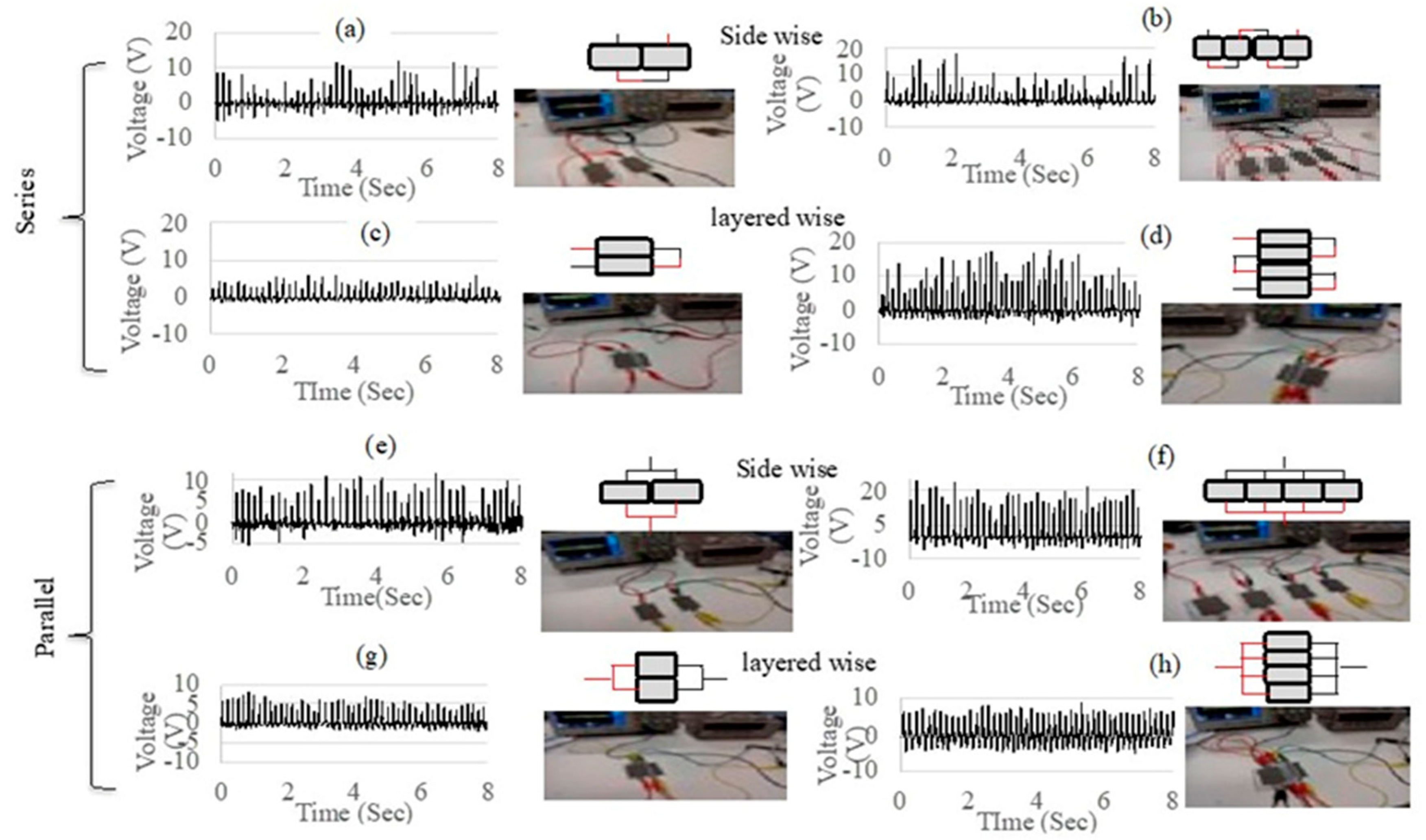
3.1. PSTS and PSTH Performance

In order to study the performance of the PSTS and PSTH, we have characterized all the important parameters, such as voltage, current, and charge generation of the device. Figure 4a,b show the output performance of the PSTS while applying repetitive pressure by finger tapping. The flexible PSTS is highly sensitive owing to its sandwich structure, where the PVDF film works as a piezoelectric source material, and due its higher sensitivity, producing a short-circuit current (Isc) of 2.36 μA and open-circuit voltage (Voc) of 5.2 V. In addition, the charge accumulation on the surface of the PSTS increases with increasing time and is about 22.4 nC after 44.5 s of tapping time.
Height of the output pulse for both the open-circuit voltage (Voc) and short-circuit current (Isc) are the same when an equal pressure is exerted onto the surface of the PSTS, as depicted in Figure 4a,b, respectively. To ensure the performance of the PSTH, we measured the voltage, current, accumulative charge, and power by varying the external load resisters, as shown in Figure 4c–f. The electric power density is fully dependent on the load applied to the PSTS, and the figure shows that the output voltage gradually increases with increasing load resistance, and it is saturated at a high resistance. However, as expected, the short-circuit current (Isc) output moderately diminishes while increasing the external load resistance. The power density was calculated following Equation (1):
p = v 2 A e f f × R L
where A = effective contact area; V = voltage drop; and RL = load resistance.
The maximum power density was achieved, 0.006 mW, from a 24 cm2 sensor surface at a resistance load 1.5 × 10⁶, as shown in Figure 4e. The charge–discharge waveform is captured in Figure 4f, done by using an oscilloscope with a 10 μF capacitor while tapping the sensor around 40 s, observing the discharging behaviour over time of the PSTH. The obtained power density of the PSTS was enough to start the low-power-consuming electronics, as demonstrated with the timer and calculator.
It is demonstrated that the conducting fabric electrodes accumulated more charges on their surfaces compared to the conventional electrodes. The rate of the collecting charge of the conducting fabrics is higher than that of the aluminium tape or carbon tape because the adhesive stick to the film decreases the rate of collecting the charge, and this is the main mechanism of producing the output power of the system. The output power can be stored using a rectifier or alternating energy storage device. From Figure 5a, it is observed that when the rectifier was integrated into the PSTS, the output voltage increased and reached up to 10 V. On the other hand, the output voltage decreased towards 5.0 V when the rectifier was taken off from the PSTS, as shown in Figure 5b. Regarding the finger tapping over the PSTS and counting the frequency 1–5 Hz, each tapping up to 5Hz was clearly recognized and the output voltage reached a 2.5 V maximum. In addition, the PSTS energy-storage capabilities depended on the rectifier integration and cyclic nature of the finger pressing and releasing conditions. Figure 5d, e indicate the output voltage of the PSTS sensor while applying forward bias and reverse bias, confirming the generation of the voltage for the harvester energy.
Depending on the energy required for wearable sensors, multiple PSTSs were connected side by side and layer by layer in series and in parallel connection to tune the voltage-generation performance. As can be depicted in Figure 6, the output voltage was measured integrating two PSTSs sidewise at approximately 12.0 V. The output voltage was increased up to 18.0 V while adding two more PSTSs sidewise through the system, as shown in Figure 6a,b. However, when the two PSTSs were connected layer-wise through the series circuit, the output voltage drastically decreases compared to a PSTS connected in series. This is probably due to the optimum distribution of the applied pressure onto sensors connected inside wise compared to layer by layer, while the applied pressure is divided among the sensors connected one after another layer by layer. However, the output voltage increases when two more PSTSs were added through the system layer-wise, as shown in Figure 6c,d. Again, we also connected the PSTS in parallel and observed the output voltage considering a sidewise and layer-wise system. From Figure 6e,f, the output voltage is increased while adding more PSTS, and it is also decreased when PSTS is added layer-wise, as shown in Figure 6g,h. Thus, it helps the user to tune from low to high energy as per the requirement to run the sensors. Eventually, where the sensor integration space is an issue, the manufacturer can easily connect them layer by layer, for instance, in shoe insole applications.

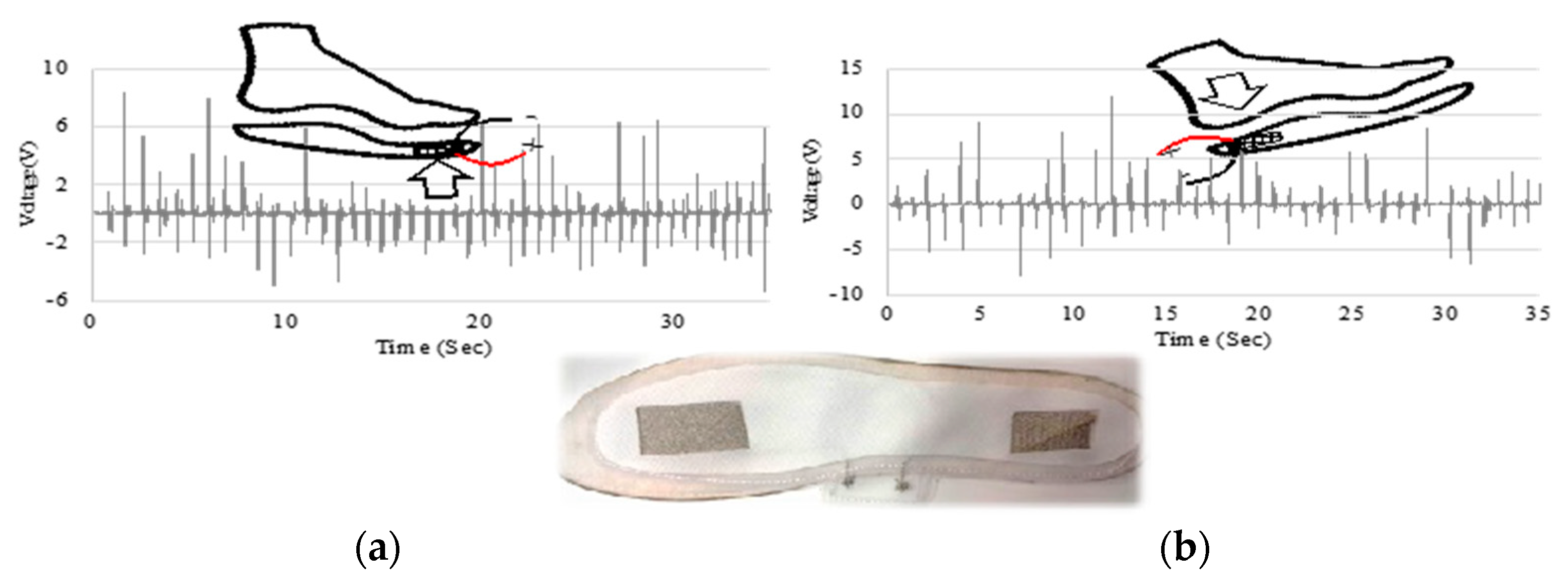
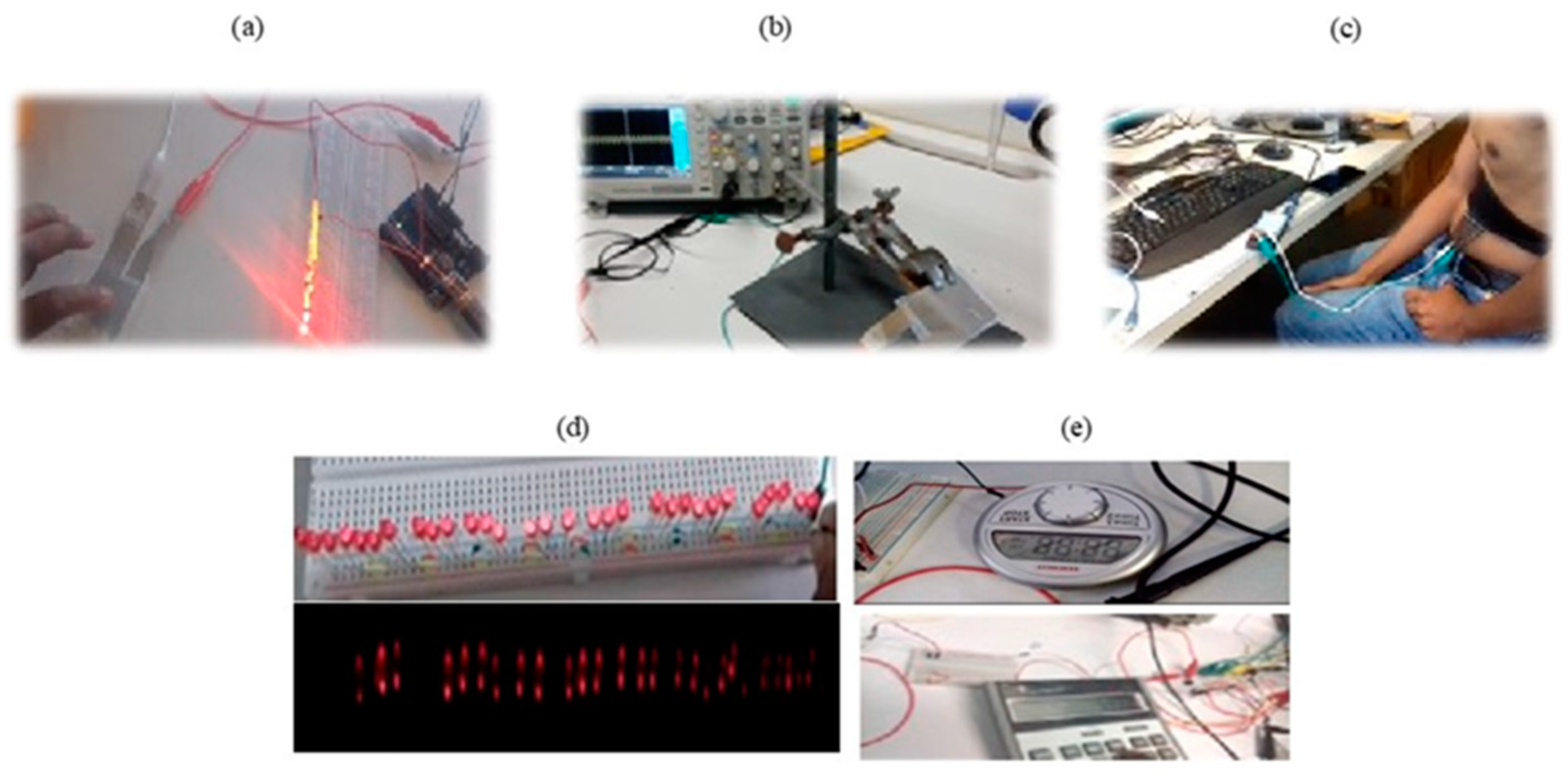
3.2. Effectiveness of the PSTS Sensor and PSTH in Wearables

The effectiveness and sensitivity of the sensor and harvester were demonstrated by the recognition of tiny water droplets, footsteps by walking, and breathing detection, etc., which makes the PSTS suitable for power generation and self-powered sensors for health monitoring applications.
We further demonstrated the PSTS to recognize the footstep while walking or running, as shown in Figure 7. In this regard, we integrated a piezoelectric sensor into a shoe insole to observe the output voltage in an oscilloscope while applying pressure to the heel and toe. The fabricated PSTS produces a high output voltage up to ~13V during heel pressing, while it provides an output voltage ~6V during toe pressing, and the signal appears unsymmetrical in both cases. It is assumed to be correlated with the unequal force applied by the heel and toe, which indicates the heel pressure is about twice as high as that of the toe. This difference happened probably due to the unequal pressure and bending deformation that occurred at the PSTS surface during walking.
As demonstrated in Figure 8 for both the sensor (PSTS) and harvester (PSTH), a touch sensor works well while the sensor is touched by hand (Supporting Video S1). In Figure 8c, the PSTS is integrated into wearable belt as a respiratory sensor and confirmed the effectiveness of the sensor at breathing recognition at different breathing conditions, namely, fast, slow, and deep breathing (Supporting Video S2). The PSTH harvester in Figure 8d,e proved that the device is able to lighten 32 LEDs and can operate electronics such as a calculator and timer with the energy stored in a capacitor by tapping the device for only 40 s by hand. The voltage accumulation of the capacitor can be observed on a multimeter while tapping the sensor by hand in Supporting Video S3. The sensitivity of the PSTS sensor, recognized by the voltage generation in the oscilloscope from water droplets, can be seen in Supporting Video S4. Thus, we can assume that raindrops can be utilised as a power-generating source on days when no sun is available to solar cells.

4. Conclusions

A flexible, bendable, and wearable piezoelectric smart textile has been developed successfully in this work. Both woven and embroidery electrodes can be useful for piezoelectric PVDF film integration to produce a piezoelectric-textile harvester and self-powered sensor device. The device, with an area of about 24 cm2, is able to store energy up to 6 μW, generated a current of 2.36 μA, and had a 22.4 nC charge against a 1.5 MΩ resistive load applying a rectifier circuit. The sensor has responded well up to 5 Hz frequencies and could be utilized in multiple sensors sidewise or layer by layer, connected in series or in parallel to elevate the power-generation level. The self-powered sensor integrated into a wearable belt and shoe insole showed their effectiveness in breathing detection and footsteps recognition during gait analysis. The generator was able to lighten about up to 32 LED while vibrating it by hand for about 40 s. The effectiveness and sensitivity of the sensor was demonstrated by the recognition of a tiny water droplets of less than 50 mg weight, which makes the device suitable for power generation and as a self-powered sensor for health-monitoring applications.

Supplementary Materials

The following supporting information can be downloaded at: https://www.mdpi.com/article/10.3390/en15155541/s1, Videos S1–S4.

Author Contributions

Conceptualization, G.H.; Investigation, I.Z.H., A.K. and G.H.; Methodology, I.Z.H.; Supervision, G.H.; Validation, I.Z.H.; writing—original draft, I.Z.H.; Writing—review & editing, A.K. and G.H. All authors have read and agreed to the published version of the manuscript.

Funding

This research received no external funding.

Acknowledgments

Financial support is gratefully acknowledged as from the Project “TCCV/PRINCESS: FFG 860474/879843” funded within the COMET and Produktion der Zukunft program by BMK as well as BMDW, as well as co-financing by the federal province Vorarlberg managed by the Austrian Research Promotion Agency (FFG).

Conflicts of Interest

The authors declare no conflict of interest.

References and Note

  1. Qin, Y.; Wang, X.; Wang, Z.L. Microfibre-nanowire hybrid structure for energy scavenging. Nature 2008, 451, 809–813. [Google Scholar] [CrossRef]
  2. Byun, K.-E.; Cho, Y.; Seol, M.; Kim, S.; Kim, S.-W.; Shin, H.-J.; Park, S.; Hwang, S.W. Control of Triboelectrification by Engineering Surface Dipole and Surface Electronic State. ACS Appl. Mater. Interfaces 2016, 8, 18519–18525. [Google Scholar] [CrossRef]
  3. Mule, A.R.; Dudem, B.; Patnam, H.; Graham, S.A.; Yu, J.S. Wearable Single-Electrode-Mode Triboelectric Nanogenerator via Conductive Polymer-Coated Textiles for Self-Power Electronics. ACS Sustain. Chem. Eng. 2019, 7, 16450–16458. [Google Scholar] [CrossRef]
  4. Tanaka, Y.; Nguyen, D.P.; Fukuda, T.; Sano, A. Wearable skin vibration sensor using a PVDF film. In Proceedings of the 2015 IEEE World Haptics Conference (WHC), Evanston, IL, USA, 22–26 June 2015; pp. 146–151. [Google Scholar] [CrossRef]
  5. Mao, Y.; Zhao, P.; McConohy, G.; Yang, H.; Tong, Y.; Wang, X. Sponge-like piezoelectric polymer films for scalable and integratable nanogenerators and self-powered electronic systems. Adv. Energy Mater. 2014, 4, 1301624. [Google Scholar] [CrossRef]
  6. Pourjafarian, N.; Withana, A.; Paradiso, J.A.; Steimle, J. Multi-Touch Kit: A Do-It-Yourself Technique for Capacitive Multi-Touch Sensing Using a Commodity Microcontroller; Association for Computing Machinery (ACM): New York, NY, USA, 2019; pp. 1071–1083. [Google Scholar] [CrossRef] [Green Version]
  7. He, J.H.; Hsin, C.L.; Liu, J.; Chen, L.J.; Wang, Z.L. Piezoelectric gated diode of a single ZnO nanowire. Adv. Mater. 2007, 19, 781–784. [Google Scholar] [CrossRef]
  8. Xue, X.; Deng, P.; Yuan, S.; Nie, Y.; He, B.; Xing, L.; Zhang, Y. CuO/PVDF nanocomposite anode for a piezo-driven self-charging lithium battery. Energy Environ. Sci. 2013, 6, 2616–2620. [Google Scholar] [CrossRef]
  9. Maiti, S.; Karan, S.K.; Lee, J.; Mishra, A.K.; Khatua, B.B.; Kim, J.K. Bio-waste onion skin as an innovative nature-driven piezoelectric material with high energy conversion efficiency. Nano Energy 2017, 42, 282–293. [Google Scholar] [CrossRef]
  10. Karan, S.K.; Bera, R.; Paria, S.; Das, A.K.; Maiti, S.; Maitra, A.; Khatua, B.B. An Approach to Design Highly Durable Piezoelectric Nanogenerator Based on Self-Poled PVDF/AlO-rGO Flexible Nanocomposite with High Power Density and Energy Conversion Efficiency. Adv. Energy Mater. 2016, 6, 1601016. [Google Scholar] [CrossRef]
  11. Guan, M.J.; Liao, W.H. On the efficiencies of piezoelectric energy harvesting circuits towards storage device voltages. Smart Mater. Struct. 2007, 16, 498–505. [Google Scholar] [CrossRef]
  12. Yin, B.; Qiu, Y.; Zhang, H.; Lei, J.; Chang, Y.; Ji, J.; Luo, Y.; Zhao, Y.; Hu, L. Piezoelectric performance enhancement of ZnO flexible nanogenerator by a NiO-ZnO p-n junction formation. Nano Energy 2014, 14, 95–101. [Google Scholar] [CrossRef]
  13. Lu, J.; Peng, Y.; Liu, W.; Qiao, S.; Li, F.; Kan, C.; Xu, C. Photoelectric dual-mode strain sensing based on piezoelectric effect. J. Lumin 2021, 238, 118237. [Google Scholar] [CrossRef]
  14. Tian, W.; Ling, Z.; Yu, W.; Shi, J. A review of MEMS scale piezoelectric energy harvester. Appl. Sci. 2018, 8, 645. [Google Scholar] [CrossRef] [Green Version]
  15. Sirohi, J.; Mahadik, R. Piezoelectric wind energy harvester for low-power sensors. J. Intell. Mater. Syst. Struct. 2011, 22, 2215–2228. [Google Scholar] [CrossRef]
  16. Chakhchaoui, N.; Ennamiri, H.; Hajjaji, A.; Eddiai, A.; Meddad, M.; Boughaleb, Y. Theoretical modeling of piezoelectric energy harvesting in the system using technical textile as a support. Polym. Adv. Technol. 2017, 28, 1170–1178. [Google Scholar] [CrossRef]
  17. Textile-Based Triboelectric Nanogenerators for Self-Powered Wearable Electronics. Available online: https://onlinelibrary.wiley.com/doi/abs/10.1002/adfm.201804533 (accessed on 24 July 2022).
  18. Hu, Y.; Zhao, Z.; Liu, Z. “Textile triboelectric nanogenerator for wearable electronics. Adv. Mater. Lett. 2018, 9, 199–204. [Google Scholar] [CrossRef]
  19. Stoppa, M.; Chiolerio, A. Wearable electronics and smart textiles: A critical review. Sensors 2014, 14, 11957–11992. [Google Scholar] [CrossRef] [Green Version]
  20. Jung, H.J.; Song, Y.; Hong, S.K.; Yang, C.H.; Hwang, S.J.; Jeong, S.Y.; Sung, T.H. Design and optimization of piezoelectric impact-based micro wind energy harvester for wireless sensor network. Sens. Actuators A Phys. 2015, 222, 314–321. [Google Scholar] [CrossRef]
  21. Liu, Z.H.; Pan, C.T.; Lin, L.W.; Huang, J.C.; Ou, Z.Y. Direct-write PVDF nonwoven fiber fabric energy harvesters via the hollow cylindrical near-field electrospinning process. Smart Mater. Struct. 2013, 23, 025003. [Google Scholar] [CrossRef]
  22. Wang, N.; Wang, X.-X.; Yan, K.; Song, W.; Fan, Z.; Yu, M.; Long, Y.-Z. Anisotropic Triboelectric Nanogenerator Based on Ordered Electrospinning. ACS Appl. Mater. Interfaces 2020, 12, 46205–46211. [Google Scholar] [CrossRef]
  23. Bai, Z.; Xu, Y.; Li, J.; Zhu, J.; Gao, C.; Zhang, Y.; Wang, J.; Guo, J. An Eco-friendly Porous Nanocomposite Fabric-Based Triboelectric Nanogenerator for Efficient Energy Harvesting and Motion Sensing. ACS Appl. Mater. Interfaces 2020, 12, 42880–42890. [Google Scholar] [CrossRef]
  24. Chakhchaoui, N.L.; Farhan, R.; Chu, Y.; Khan, U.; Eddiai, A.; Omari, L.E.H.; Meddad, M.; Hajjaji, A.; Cherkaoui, O.; Boughaleb, Y. vanlangenhove Flexible smart textile coated by PVDF/Graphene oxide with excellent energy harvesting toward a novel class of self-powered sensors: Fabrication, Characterization and Measurements. Preprints 2021, 2021030786. [Google Scholar] [CrossRef]
  25. Le, A.T.; Ahmadipour, M.; Pung, S.; Ahmadipour, M. Journal Pre-proof. 2020
  26. Wu, J.; Mahajan, A.; Riekehr, L.; Zhang, H.; Yang, B.; Meng, N. Nano Energy for high power energy storage. Nano Energy 2018, 50, 723–732. [Google Scholar]
  27. Sarker, M.R.; Mohamed, A.; Mohamed, R. A new method for a piezoelectric energy harvesting system using a backtracking search algorithm-based pi voltage controller. Micromachines 2016, 7, 171. [Google Scholar] [CrossRef] [PubMed] [Green Version]
  28. Aqueveque, P.; Osorio, R.; Pastene, F.; Saavedra, F.; Pino, E. Capacitive Sensors Array for Plantar Pressure Measurement Insole fabricated with Flexible PCB. In Proceedings of the 2018 40th Annual International Conference of the IEEE Engineering in Medicine and Biology Society (EMBC), Honolulu, HI, USA, 18–21 July 2018; pp. 4393–4396. [Google Scholar] [CrossRef]
Figure 1. Working principle of a piezoelectric material when applying and releasing pressure.
Energies 15 05541 g001
Figure 2. Fabrication process of the piezoelectric smart-textile sensor (PSTS) and harvester (PSTH), where (ac) represent schematic diagrams of the conductive textile, polarized PVDF film, and a complete sensor, respectively; (df) show the real-world manufacturing steps of the PSTS and PSTH, respectively.
Energies 15 05541 g002
Figure 3. Oscilloscopic analysis of the PSTS (a); the entire circuit diagram (b); the experimental setup by hand pressing (c); the output voltage response (d); the short-circuit current (e,f) of the enlarged view of a complete single peak in the current signal.
Energies 15 05541 g003
Figure 4. Output performance of the sensor by repetitive tapping pressure: (a) open circuit voltage; (b) short circuit current; (c) charge accumulation over tapping time; (d) real-time change in voltage and current due to the corresponding change in the resistive load; (e) the correlation of the power generation against different resistances; and (f) the charging and discharging behaviour of the device under tapping start/stop.
Energies 15 05541 g004
Figure 5. The voltage responses of the PSTS was recorded under different condition by measuring (a) with and (b) without the rectifier circuit while tapping with one’s finger; (c) the output voltage at different frequencies, 1–5 Hz; (d) with forward bias and (e) reversed bias.
Energies 15 05541 g005
Figure 6. Oscilloscopic response from generating an output voltage via multiple sensors connected in series (ad) and in parallel (eh); (a,b,e,f) sidewise and (c,d,g,h) layer-wise connected PSTS.
Energies 15 05541 g006
Figure 7. (a) Output voltage of the PSTS pressing by toe. (b) Output voltage of the PSTS pressing by heel.
Energies 15 05541 g007
Figure 8. Demonstration of the PSTS as (a) a touch sensor; (b) water droplets for voltage generation; (c) breathing detection; (d) a PSTH lightening 32 LEDs in the dark (bottom) and at daylight (top); and (e) stored energy powering electronics such as a timer and calculator in operation.
Energies 15 05541 g008
Publisher’s Note: MDPI stays neutral with regard to jurisdictional claims in published maps and institutional affiliations.

