Article

Hybrid Power Management Strategy with Fuel Cell, Battery, and Supercapacitor for Fuel Economy in Hybrid Electric Vehicle Application

School of Electrical Engineering (SELECT), Vellore Institute of Technology, Vellore 632014, Tamil Nadu, India
*
Author to whom correspondence should be addressed.
Energies 2022, 15(12), 4185; https://doi.org/10.3390/en15124185
Submission received: 14 March 2022 / Revised: 4 May 2022 / Accepted: 9 May 2022 / Published: 7 June 2022
(This article belongs to the Special Issue Smart Energy Management for Microgrid and Photovoltaic Systems)

Abstract

:
The power management strategy (PMS) is intimately linked to the fuel economy in the hybrid electric vehicle (HEV). In this paper, a hybrid power management scheme is proposed; it consists of an adaptive neuro-fuzzy inference method (ANFIS) and the equivalent consumption minimization technique (ECMS). Artificial intelligence (AI) is a key development for managing power among various energy sources. The hybrid power supply is an eco-acceptable system that includes a proton exchange membrane fuel cell (PEMFC) as a primary source and a battery bank and ultracapacitor as electric storage systems. The Haar wavelet transform method is used to calculate the stress σ on each energy source. The proposed model is developed in MATLAB/Simulink software. The simulation results show that the proposed scheme meets the power demand of a typical driving cycle, i.e., Highway Fuel Economy Test Cycle (HWFET) and Worldwide Harmonized Light Vehicles Test Procedures (WLTP—Class 3), for testing the vehicle performance, and assessment has been carried out for various PMS based on the consumption of hydrogen, overall efficiency, state of charge of ultracapacitors and batteries, stress on hybrid sources and stability of the DC bus. By combining ANFIS and ECMS, the consumption of hydrogen is minimized by 8.7% compared to the proportional integral (PI), state machine control (SMC), frequency decoupling fuzzy logic control (FDFLC), equivalent consumption minimization strategy (ECMS) and external energy minimization strategy (EEMS).

1. Introduction

Freshwater, electricity and the atmosphere are interconnected factors that have emerged as the most significant and prominent topics in engineering. In particular, global warming and resource shortages are key challenges that have been addressed. As a result, manufacturing practices and engineering communities are rapidly transforming the approach to energy-efficient applications; environmental and economic considerations are driving the transportation sector’s development [1]. Transportation is mostly reliant on fossil fuels and produces greenhouse gases. Here, several attempts have been made to enhance the requirement of fuel cells (FCs) in transportation applications as a sustainable electric power source that emits no greenhouse gas [2,3]. The usage of fuel cells in electric vehicles, trains, aircraft, etc., helps to protect the environment, thereby providing a clean fuel source for transportation [4]. Fuel cells are new energy conversion solutions that have many advantages over traditional devices, including high energy efficiency, small size, environmental safety, long lifespan and so on. The proton exchange membrane fuel cell (PEMFC) seems to be the most suitable form for use in automotive applications because it has a high density in producing electricity, leading to lower heat generation and resulting in a lower temperature, which is important in transportation applications. The key drawback of fuel cells in transportation applications is the low dynamic response. Since the fuel cell lags against load variations, this means that they are unable to react appropriately to sudden changes in load.
As a result, the fuel cell should be associated with the battery storage and ultracapacitor (UC) [5,6], while the battery storage seems to have a high-power density, with some limitations, such as lower energy capacity, a long charging period, a high price and a short lifespan. The usage of a hybrid FC/B/UC network is the best strategy to overcome the described issues. This type of combination allows the hybrid sources to exploit their unique characteristics. The battery bank acts as an energy buffer, whereas the ultracapacitor supplies transient peak power units. A power management scheme (PMS) is essential to achieve certain hybridization and achieve the main goal of distributing load requirements through power sources. By limiting the fuel cell performance to wider operating levels, the PMS successfully maintains the consumption of hydrogen and enhances the energy efficiency. To regulate the system load among these integrated input sources, a set of conventional PMS was implemented [7].
They are PI control, state machine control (SMC), the equivalent consumption minimization scheme (ECMS), fuzzy logic control (FLC) and the external energy minimization scheme (EEMS), and several other modern optimization-based techniques have also been developed. In Ref. [8], Wang et al. developed a power management technique for state machine control (SMC) that contains the battery bank, fuel cell and ultracapacitors as a multi-input network. In Ref. [9], power management with the proportional integral (PI) technique was implemented by the authors to regulate the energy across photovoltaics (PV), fuel cells (FCs), batteries and supercapacitors (SCs). Multiple operational modes were operated for a hybrid device consisting of B/SC/FC in [10] using a rule-based energy management technique. In Ref. [11], Jiang et al. proposed a dynamic programming (DP) method for reducing hydrogen consumption in a hybrid power system with a fuel cell, battery and supercapacitor to provide energy to the power train. The authors Li et al. [12] implemented a novel power management technique with rule-based fuzzy logic control with various multi-input sources, i.e., at first, the input sources consist of FC/B, and, later, the input sources consist of B/SC/FC for powering an electric vehicle.
In Ref. [13], the authors present an adaptive neuro-fuzzy inference system (ANFIS) to adequately manage the power between the FC and battery often used to provide power to electric vehicles (EV). The authors Chen et al., in [14], proposed a power management technique divided into two sections, a wavelet-based and a radial-based solution, to refine the power output in an electric vehicle using neural networks. The authors designed a novel energy management mechanism focusing on wavelet transform approaches for controlling power among FC/B/SC to EVs. A Gray Wolf Optimizer (GWO) was designed by authors Djerioui et al. considering FC/B/UC as a hybrid power system for electric vehicle applications [15]. In a parallel HEV, an FLC-based technique was designed to optimize the SoC, enhance fuel efficiency, minimize NOx emissions and ensure greater drivability. For power split across accessible sources, an FLC-based intelligent energy management agent (IEMA) has been developed. The author of Ref. [16] created an FLC to optimize system operation using the energy demands and the speed of the vehicle, as well as the SoC, as input variables.
A rule-based method was utilized in a parallel HEV to increase fuel economy in Ref. [17]. In Ref. [18], FLC was used in a parallel HEV to establish a predictive EMS in terms of speed as well as reinforcement learning. In consideration of SoC and torque limitations, an FLC-enabled EMS for series HEVs has been designed. A dual FLC technique for a parallel HEV is reported in Ref. [19], in which membership functions (MFs) are optimized to use a genetic algorithm (GA) to improve performance when compared to the dynamic programming (DP) approach. For controlling the power across FC/B/SC, the authors implemented an equivalent consumption minimization scheme (ECMS) employing a sequential quadratic programming approach. ECMS is a greedy (immediate) optimization method. The ECMS cost factor takes into account fuel consumption as well as the cost of using battery energy. The equivalency factor is the weighting for these penalties. Pontryagin’s Minimum Principle (PMP) can be used to generate ECMS. As a result, if the battery state of charge does not exceed the limitations, ECMS provides the best fuel efficiency. However, identifying the best equivalency factor necessitates a priori knowledge of the full driving cycle. This type of information is not widely available. Adaptive ECMS (A-ECMS) is a suggested method for estimating the appropriate ECMS equivalence factor for industrial cases [20]. An A-ECMS is also utilized to keep the battery’s level of charge within the limits. The equivalency factor is determined in A-ECMS by using an instant estimation algorithm or even a prediction-based estimation approach. In Ref. [21], Marzougui et al. designed a new power management technique incorporating three different aspects—a rule-based algorithm, fuzzy-based control and flatness control—for FC/B to supply electric vehicles (EV). Authors Fathy et al. suggested a novel energy management technique focusing on the slap swarm methodology (SSA) for maintaining energy in FC/BSC by assessing the consumption of hydrogen as the main objective function. In Ref. [22], Li et al. adopted three methods to study the performance of energy management by combining the sources of FC/SC for sourcing an excavator: firstly, the dynamic programming method is applied; second, a model predictive control is designed, and third, Pontryagin’s Minimum Principle (PMP) with reduced consumption of hydrogen is applied. Multiple metaheuristic architectures for controlling the capacity of fuel cell hybrid power systems for supplying aircraft were proposed by authors Zhao et al.
To reduce the cost of the overall system, the authors Yu et al. [23] introduced a novel hybrid FC/B/SC-fed EV architecture. In Ref. [24], to deliver power to a hybrid energy network, the authors developed a rule-based distribution method; in addition, to measure the strength of the batteries and ultracapacitors, a Bayes Monto Carlo methodology was also implemented. Authors Thounthong et al. implemented an adaptive energy management system for FC/B/SC for electric vehicle applications. In Ref. [25], authors Han et al. designed a two-level power management technique for solar (PV), fuel cell and battery power that is integrated into a DC microgrid. In [26], the author examines various approaches to energy management strategies used in maintaining electric power in electric vehicles that are powered by fuel cells. The authors Bendjedia et al. investigated three power management approaches to create a hybrid energy storage system (HESS) that represents fuel cells plus an additional source for powering small vehicles.
Various energy management solutions for EVs driven by FC are reported in [27]. Bizon et al. suggested a new optimization approach based on a two-dimensional mechanism that characterizes the fuel economy of hybrid vehicles [28]. The authors Li et al., in [29], combined the fuzzy logic and wavelet transformation approaches to optimize the energy management of hybrid tramways. The research’s primary feature is the development of an optimal EMS for minimizing the hydrogen demand and loss of FC functionality. None of the individual algorithms completely address all optimization challenges. This is in line with the No Free Lunch Scientific Theory, discussed in [30], which signifies that novel optimization algorithms are indeed required in the field of research in the power management of EVs. Measuring hydrogen consumption with a hybrid energy storage system to the DC voltage bus is a key issue that might be addressed. It also consolidates all DC/DC converters into a single unit. This research work describes a novel hybrid energy management system that integrates an external energy minimization strategy (ECMS) with an adaptive neuro-fuzzy inference system (ANFIS) and functions as an adaptive control system. Regarding cost and lifespan cycle maintenance, this control system is simulated with MATLAB/Simulink software to reduce hydrogen utilization in the FC, as well as to maintain the battery levels (SoC percent) as high as possible. A hybrid power management scheme is proposed for better fuel economy in a hybrid electric vehicle using FC/B/UC and PMS configurations, as illustrated in Figure 1. The paper is structured as follows. Section 2 presents the system optimization problem. Section 3 presents the modeling and description of the hybrid power storage system. Section 4 explores various power management strategies (PMS). Section 5 shows the proposed hybrid power management strategy (ECMS + ANFIS). Section 6 elaborates on the results and comparisons of power management schemes. Section 7 presents the main conclusions that were obtained from the realization of the present work.

2. System Optimization Problem

To fulfill maximum power needs, hybrid systems rely on at least one to two sources of energy. This system is combined with one or more renewable resources. Hybrid systems are often designed to have an optimization technique working in conjunction with an adequate power management system to reduce fuel usage and ensure system dependability and functioning with an appropriate power management system (PMS), which assesses which source provides the demand with its required power, as well as how much energy this source might deliver [31]. To achieve this objective, hybrid system components such as fuel cells, batteries as well as supercapacitors are combined for an optimal minimization and control method to obtain the power level set by the PMS depending on the requirement of load [32]. The PEMFC electrical energy, as well as the power storage systems—the Li-ion battery bank and UC bank—will be changed to relative hydrogen usage. The corresponding hydrogen usage for a particular load named “C” is determined by a combination of the utilization of hydrogen in a fuel cell (CFC) and the usage of hydrogen in a battery (Cbatt) as well as a supercapacitor (Csc). The following equation represents a mathematical model for optimizing fuel usage:
  P FC = min C FC + k 1 · C batt + k 2 · C sc
Here, P FC represents the output power for a fuel cell, whereas k 1   and k 2 denote the converter penalty coefficient for the consumption of hydrogen. Meanwhile, the battery converter controls the DC power, and the ultracapacitor power can be ignored in the optimization procedure [33,34,35,36]. Here, the UCs are drained or recharged using the same power from a battery bank, distributing the total load between the fuel cell and also the batteries across each phase. Then, the optimization problem is expressed as follows:
x = P FC + k 1 · P batt  
Finding the optimal solution (x) minimizes (F):
F = P FC + k 1 · P batt T .  
Here, x represents the optimal solution, k 1 denotes the penalty coefficient and T denotes the sampling time. The penalty coefficient is given as
k 1 = 1 2 μ SoC 0.5 SoC max SoC min SoC max SoC min
The estimated hydrogen usage of the battery (Cbatt) can be computed using the power of the battery (Pbatt) and the state of charge of the battery. Now, under the conditions of equality,
P load = P FC + P batt
with the constraints of boundaries
  P fc _ min P FC P fc _ max  
P batt _ min P batt P batt _ max
0 k 1 100
This might be the overall target value, and it is a fundamental issue for every hybrid power system with hydrogen fuel and energy storage devices, but this multi-objective optimization model has been addressed clearly in this paper.

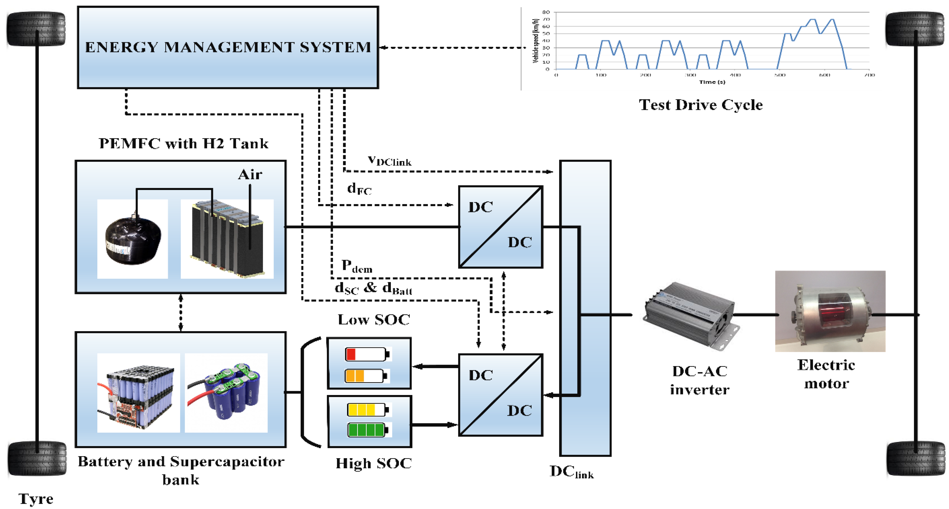
3. Modeling and Description of Hybrid Power Storage System

A hybrid energy storage system (HESS) is a combination of PEMFC, Li-ion batteries and a supercapacitor. These three sources are often considered as an FCHEV to ensure reliable power sufficiency of the load. The configuration of the hybrid system analysis can be seen in Figure 1. The fuel cell and rechargeable battery, as well as capacitors, are the three sources of power in this setup. A DC/DC boost converter has been used with the fuel cell to enhance its voltage level towards the desired level and sustain this at the outputs. There are batteries, where a DC/DC bidirectional power device converts variable power to a fixed voltage. Supercapacitors, similarly to some other capacitors, have been integrated into bidirectional converters, which enable power to be exchanged in both directions.

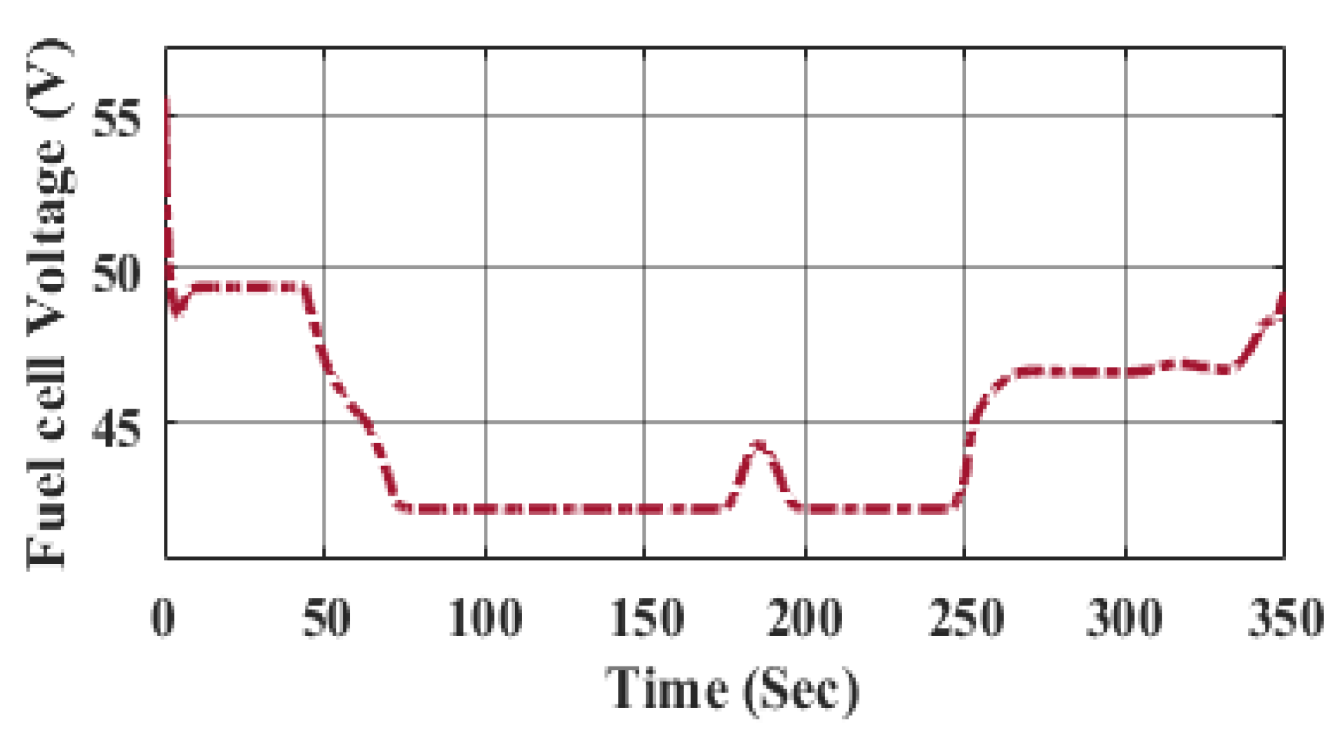
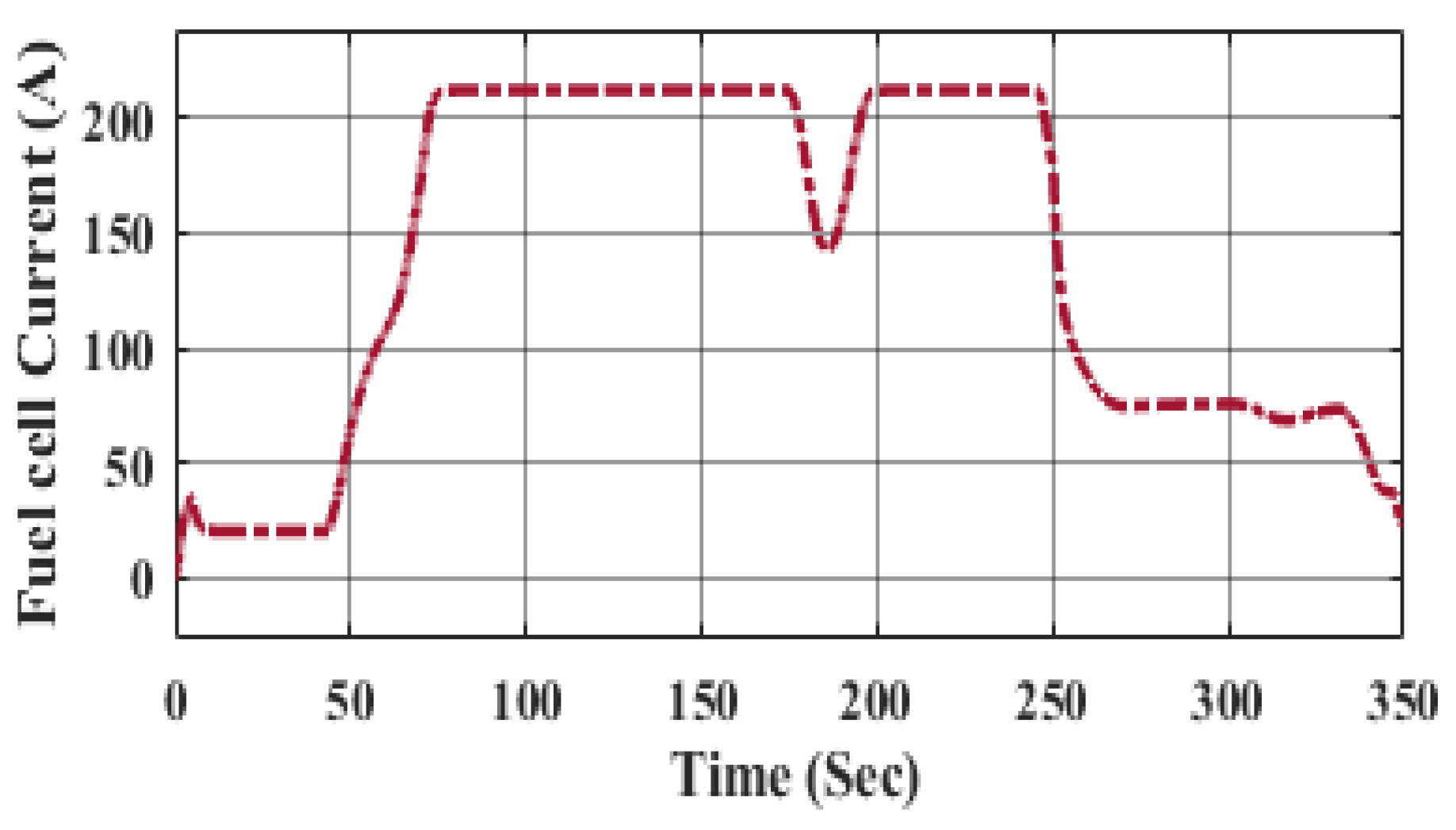
3.1. Proton Exchange Membrane Fuel Cell (PEMFC)

A fuel cell is a power conversion device that converts chemical energy in hydrogen fuel to electrical power without using heat or mechanical power. As per the chemical process defined in Equation (9) [14], the basic working principle of a fuel cell is described by a chemical process in which oxygen and hydrogen are linked together to form power, heat and water.
2 H 2 + O 2 H 2 O + electricity + heat  
There are several types of fuel cell technology, which are categorized depending upon their electrolytes. Another type of fuel cell that is widely used in vehicular applications is the proton exchange membrane fuel cell (PEMFC) [15]. There are several new fuel cell prototypes, each with a combination of benefits and drawbacks based on the topic under study. Any model must be concise and accurate. Furthermore, this paper presents a simple electrochemical concept that might be used to determine the behavior of such a fuel cell both in dynamic and static conditions [16]. The hydrogen fuel design used in this study is based on the interaction between both the fuel cell voltage level and hydrogen, water, plus oxygen absolute pressures. The specifications of the fuel cell stack are illustrated in Table 1. The fuel cell voltage is regulated via oxygen and hydrogen relative pressures, the chemical process temperature of membrane hydration and also the output current. The mathematical model is given in [17].
V FC = E Nernst V act V ohmic V con
where E Nernst represents the mean value of thermodynamic potential in every single cell unit and it is calculated by Equation (11) [10].
E Nernst = 1.229 0.85 × 10 3 T 298.15 + 4.3085 × 10 5 T In P H 2 + 0.5 × In P O 2
Here,
V act = Activation voltage drop;
V ohmic = Ohmic voltage drop;
V con = Concentration voltage drop.
Hence, for N number of cells connected in series, the stack voltage V s t a c k is described as
V s t a c k = N · V F C  
The fuel cell’s polarization curves indicate the voltage of the battery as a factor in the output current under several temperatures plus hydrogen pressure levels. The overall polarization patterns for FCs increase as the optimal temperature and hydrogen pressure reduce. As much as this is provided by oxygen and fuel to sustain a chemical reaction mechanism, a fuel cell can produce a constant amount of power. Proton exchange membrane fuel cells are widely used in automotive applications due to their high-power density and low and moderate operating temperatures [18]. Furthermore, its effectiveness when reacting under peak load is restricted because of certain chemical processes that occur in FCs [19]. As an outcome, such sources are integrated into the batteries as well as the supercapacitor-based hybrid storage systems.

3.2. Supercapacitors

Supercapacitors are one of the recent advancements for power storage devices, especially in integrated devices. A capacitance (Csc) is linked to an equivalent series resistance Rsc under this setup. The parameters of UC are shown in Table 2. The below formula is used to determine the supercapacitor voltage (Vsc) as a result of the SC current (Isc):
  V s c = V 1 R s c × I s c = Q s c C s c R s c × I s c    
where Q SC denotes the quantity of electricity present in the cell, and the power of the supercapacitor is calculated by using Equation (14),
  P SC = Q SC C SC × I SC R SC × I SC 2  
Utilizing supercapacitors as a storage system in such an electric vehicle implies the construction of such a stacking of cells, where NS cells are interconnected in series and Np cells are parallelly connected. Equations (15) and (16) determine the capacity and resistance of the supercapacitor stack.
  C SC = C elem · N P N S  
  R SC = R elem · N S N P
Equations (17) and (18) determine both the current and voltage of a stack as a measure of such component’s current and voltage [20].
V SC = N S · V elem
I SC = N P · I elem

3.3. Battery

The battery is designed with a modest controlled power supply in series with such a fixed resistance [21]. Li-ion battery specifications are given in Table 3. Equation (1) defines the battery voltage Vbat (18).
V b a t t = E R b a t · I b a t  
The controlled source voltage is calculated by using Equation (19).
E = E 0 K Q Q 0 i · dt + A · exp B i · dt
where E represents no-load voltage (V), E 0 denotes a constant voltage of the battery (V), K denotes the polarization voltage (V), Q indicates the capacity of the battery (Ah), whereas A denotes the amplitude of the exponential zone (V) and B denotes the inverse time constant of the exponential zone (Ah)−1.

4. Power Management Strategies (PMS)

By using a reliable PMS, one can control the power response of HESS with load demand. In this paper, a hybrid power management design is obtained, as shown in Figure 2, and the requirements are listed in Table 4. Significantly, the PMS relies on obtaining the reference power of fuel cells.
A reliable power management scheme (PMS) should essentially ensure the following:
  • Lower consumption of hydrogen ( H 2 ) (gm) of PEMFC;
  • DC bus voltage regulation should be desired value;
  • Tracking the battery and SC set-point values;
  • Corroborate the global constancy of the system structure;
  • The system should operate at a high level of efficiency;
  • The long life cycle of a hybrid energy storage system (HESS).
These are attained by using a reliable PMS. The proper PMS controls the power response of HESS with load demand. In this work, the power management design requirements are as listed in Table 4. Significantly, the PMS relies on obtaining the reference power of fuel cells. Various types of PMS are considered in detail. Managing the power of HESS, which comprises the PEMFC, Li-ion batteries and SC, is reported as follows.

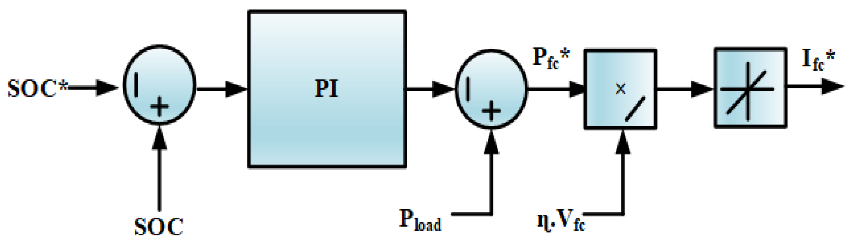
4.1. Classical Proportional Integral (PI) Control Method

The amount of the HESS’s energy is identical to the load energy. This PI strategy controls the SoC of the battery by using a PI regulator, as illustrated in Figure 2.
Fuel cell reference power is attained by regulating the battery power by using a PI controller. As a result, the rated output of the PI controller is estimated by the predetermined rate (proportional) and predefined rate (integral) of its input. If the battery’s SoC is higher than the actual rate, then the FC’s power is reduced, and the battery supplies the load with maximum power. If the battery’s state of charge (SoC) is less than the set-point, the fuel cell provides power to the load. The major role of the PI controller is that when the battery’s SoC exceeds the average SoC (SoC*), the controller permits the battery to power the demand, and the gains of PI are to be tuned online to obtain a better response [22]. A block diagram of the PI scheme is illustrated in Figure 2. The transfer function of the PI controller is given in Equation (21) [22],
P batt = K P + K i S · SoC SoC  
Here, the output current of the FC I FC is determined in terms of fuel cell output power P FC , which remains obtained from the controller and output voltage of the FC V FC .

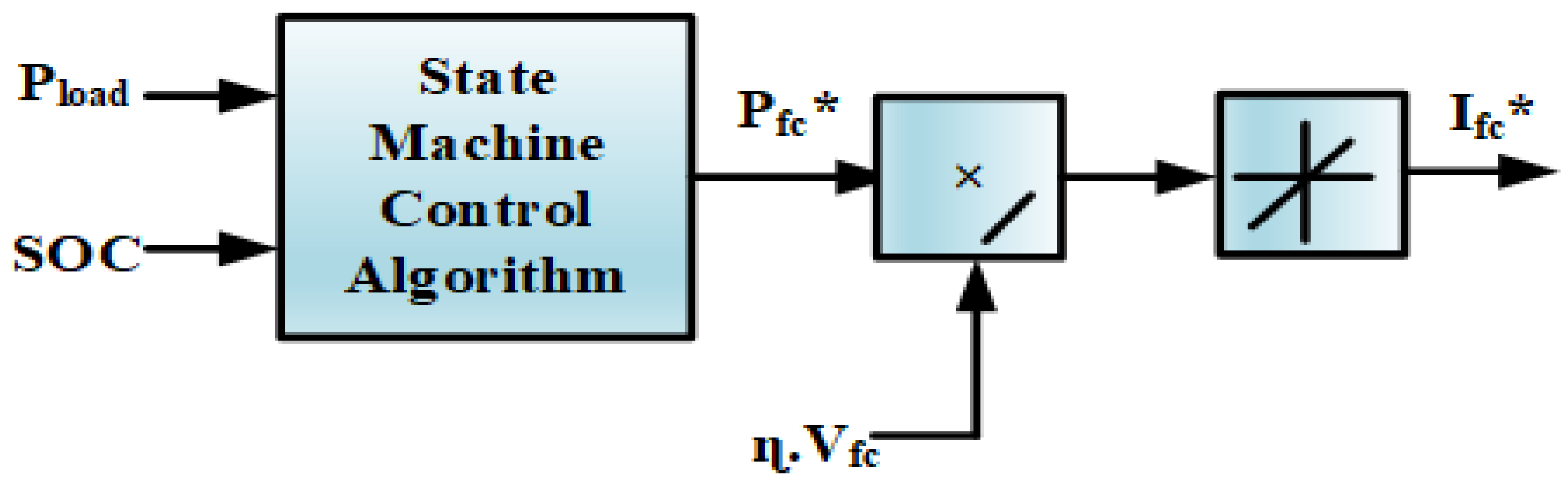
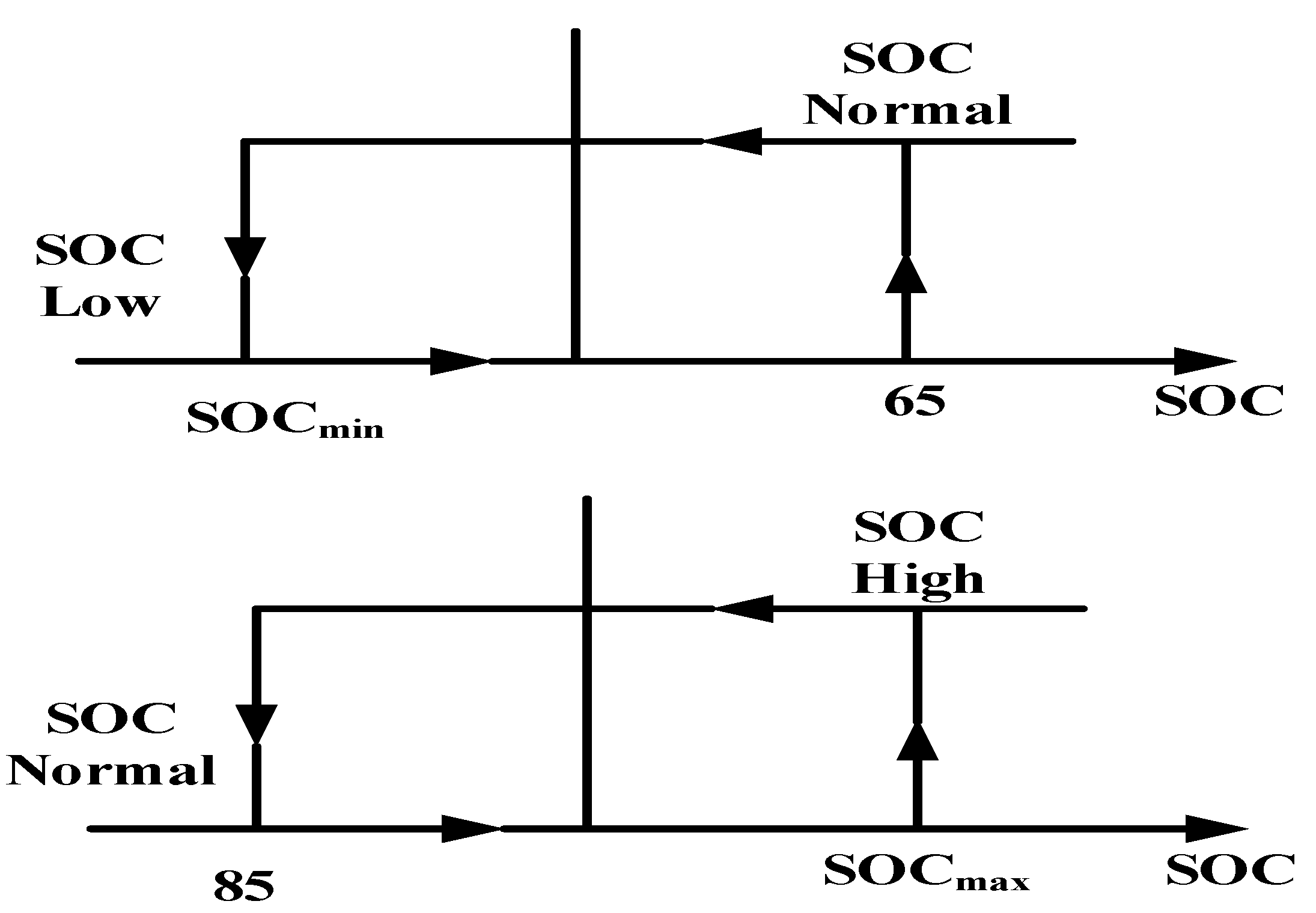
4.2. State Machine Control Approach

Figure 3 shows the control technique for the state machine scheme. This scheme is executed in eight states. In this strategy, the power of the FC can be determined through the load power ( P load ) and SOC of the battery bank. The reference power of the fuel cell is the output of the SMC strategy.
By dividing the output of SMC by the voltage of the FC and efficiency of the boost converter, the FC reference current is attained [23]. While switching the states from one to another, hysteresis control is required for the SMC strategy, which may affect the PMS’ response to changes in load demand, and the pattern is shown in Figure 4.

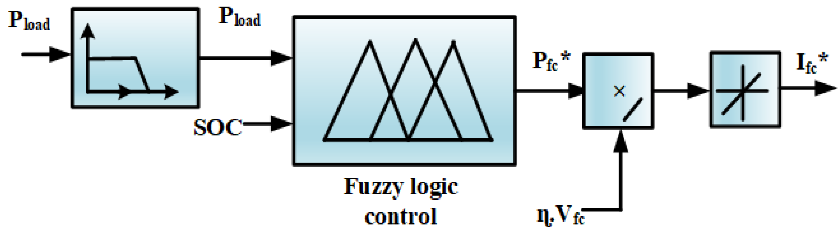
4.3. Frequency Decoupling Fuzzy Logic Control Scheme (FDFLCS)

This method permits the structure of the fuel cell to accommodate a load request with a lower frequency while the battery and supercapacitors supply the load demand with a higher frequency. The control technique is shown in Figure 5. The vital advantage of this scheme is that the Li-ion battery’s mean energy is closer to zero, ensuring a narrow range of SoC [24]. A filter is used for frequency decoupling, and a fuzzy logic controller is required to maintain the battery’s state of charge within a certain range.

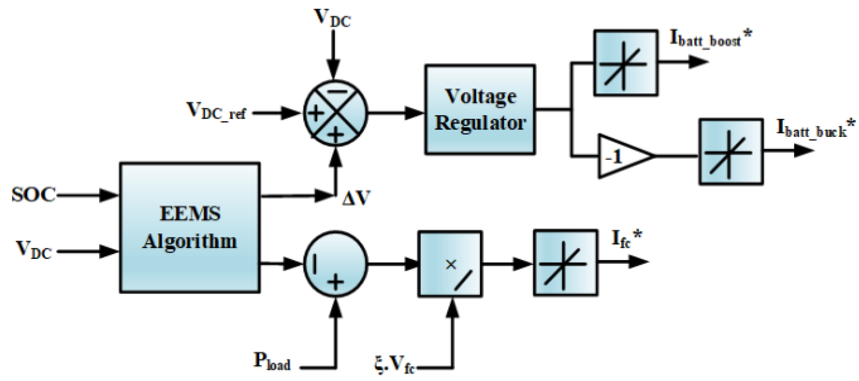
4.4. External Energy Maximization Strategy (EEMS)

In FCHEV, for upgrading the performance of HESS, it is important to interchange the energy optimally within the FC, SC and also the battery. This is achieved by reducing the fuel cells’ hydrogen consumption (H2) by maintaining the limits of the state of charge of the SC and battery. In this EEMS technique, the hydrogen consumption (H2) is minimized by raising the battery and SC demand. The EEMS technique requires the battery and SC cost function; it does not require the determined battery energy calculation. In Figure 6, it is shown that the EEMS algorithm’s inputs are the voltage of the DC bus and battery SoC or supercapacitor, while the outputs are the charge/discharge voltage V for the supercapacitor and battery reference power. Thus, a comparison of the battery and load power for the FC’s reference power via the FC current I FC is derived. The SC charge/discharge voltage is obtained by estimating the actual DC bus voltage through the sum of V dc . ref ,   a , the reference voltage of the DC bus and the SC’s voltage. In the process of this EEMS optimization problem, the SC charge/discharge voltage V and power of the battery P batt have to be assessed. The minimized objective function is the power supplied via both secondary sources during a certain period of intermission, which is described in Equation (22) [25].
Minimize
  J = P batt .   T + 1 2 · C r · V 2  
Based on the battery’s power output, the EEMS optimization procedure is carried out and the key parameter is represented by inequality constraints, and the constraints are subject to
  P batt . T     SoC SoC min · V batt · Q
whereas the power of the battery and voltage of the DC bus parametric inequality constraints are formulated as follows:
P batt min P batt P batt max
  V DC min   V DC V DC max  
Here, P batt . T denotes the delivered battery power over a sampling time V . C r represents the rated capacitance of SC. V DC min and V DC max denote the bus voltage minimum and maximum limits. V batt represents the optimum voltage of the battery, and the rated capacity of the battery is denoted by the letter Q.

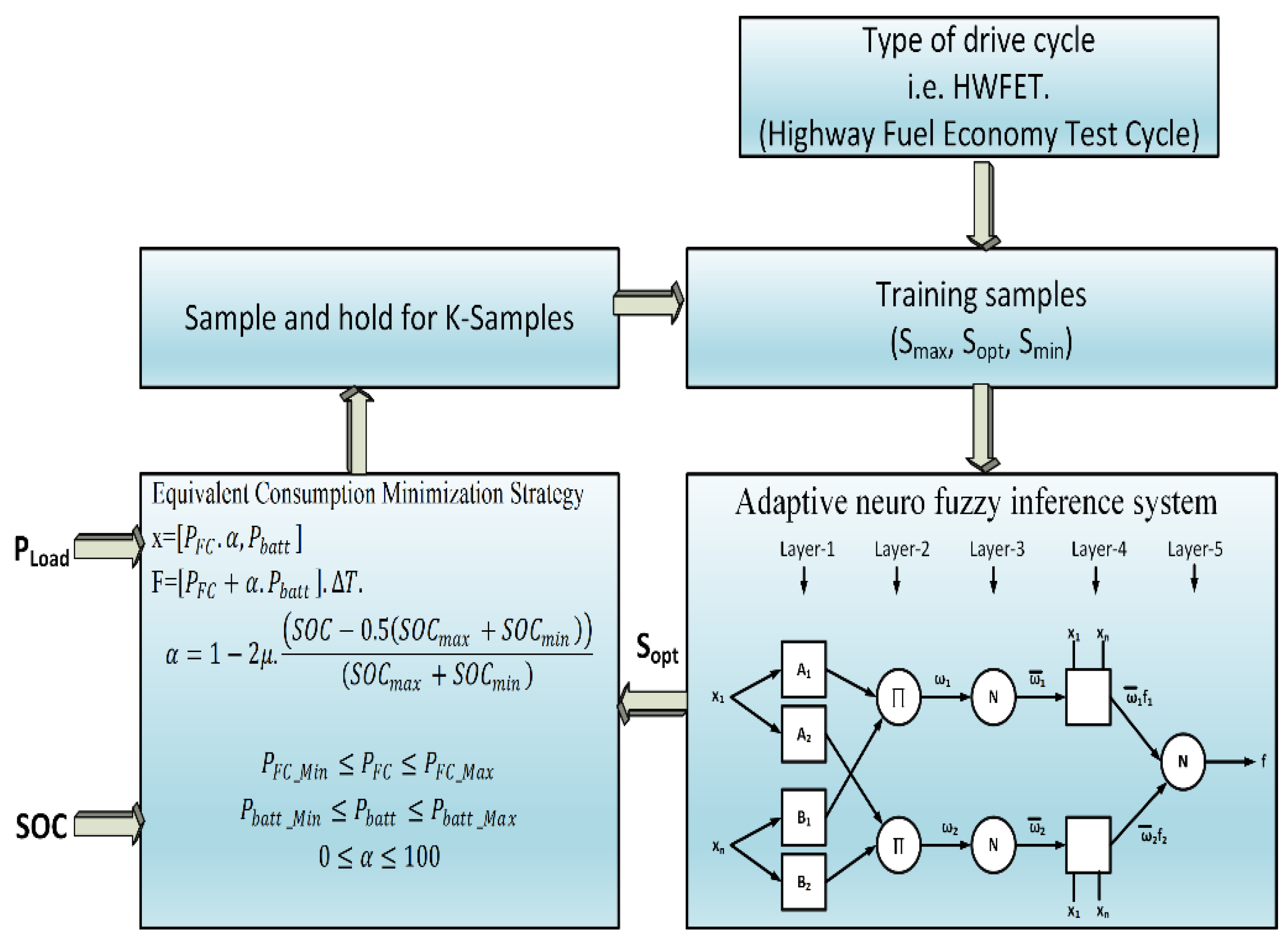
5. Proposed Hybrid Power Management Strategy (ECMS + ANFIS)

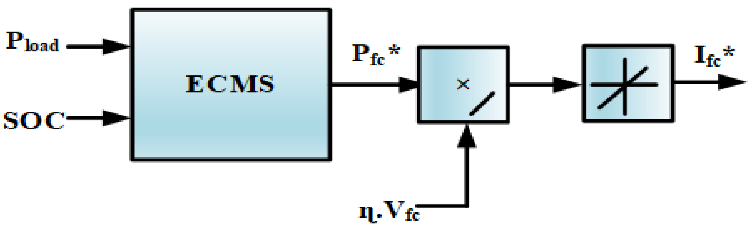
5.1. Equivalent Consumption Minimization Strategy (ECMS)

To reduce hydrogen usage and extend the life of a fuel cell, Adaptive-ECMS is introduced for the duration of a cell’s life. The primary concept of ECMS is to convert electricity usage through energy storage devices to corresponding hydrogen consumption with a combination of equivalent and actual hydrogen consumption from fuel cells being kept as low as possible, which is shown in Figure 7. Similarly, various limits have been placed to ensure that the energy sources continue to function effectively. The optimization function is as follows [26,27]:
min f w t = m FC t + m BA t + m SC t I FC min I FC I FC max I SC min I SC I SC max dI FC I FC t I FC t 1 T dI FC  
IFC* represents fuel cell reference current. Here, f w t denotes utilization hydrogen consumption at sample time t , m FC t represents the usage of hydrogen in fuel cells, whereas m BA t indicates that the hydrogen demand is comparable to the battery and m SC t indicates that the hydrogen demand is identical to the ultracapacitor, while IFC and ISC indicate the current flowing through the fuel cell as well as the UC correspondingly. Several other respective penalty parameters are incorporated into the optimization problem of Equation (9), which are given in Equation (10), to enable the fuel cell to obtain its optimum efficiency location within the efficient power boundary. Meanwhile, the charge sustenance of the energy storage systems is maintained, which means supporting the state of charge of the UC and battery to be approximately equal to their initial conditions.
f w t = K FC m FC t + K BA m BA t + K SC m SC t = K FC m FC t + K BA λ BA P BA t + K SC λ SC P SC t  
Here, KBA and KSC are penalty factors that cover a range of SoC for energy storage sources such as UC and batteries and the difference between the maximum and minimum SoC. Meanwhile, KFC represents the cost factor for hydrogen fuel efficiency and λ BA and λ SC indicate comparable factors. P BA t as well as P SC t denote the power of the battery bank and UC bank. The penalty factor for fuel cell efficiency is expressed as in Equation (28) [27]:
  K FC = 1 2 η η opt η max η min 2   η 0.4   1 2 η η opt η max η min 4   η < 0.4
where n indicates instant efficiency; nopt represents adequate efficiency, which is 0.4283 approximately; nmax denotes the maximal efficiency of 0.4283, and the base efficiency is denoted by nmin. Whenever the performance of a fuel cell system declines under 0.4, a significant penalty rate (KFC) is estimated to discontinue or maintain the fuel cell to supply energy based on the driving conditions of HEV depending on the batteries and SC state of charge levels. KFC are 2 and 4 for two circumstances that are governed by the drive cycle generation capacity. KFC regulates the pursuit of optimal efficiency and the limitations of the high-performance region (efficiency beyond 0.4). The KBA cost rate for the SoC of the battery is given in Equation (29) [28,29]:
K BA = 1 2 u B int B max B min 4   B min u B max 1 2 u B int B max B min 20   u < B min , u > B max
Here, u denotes the battery’s current state of charge. Bmt denotes the battery SoC. Meanwhile, Bmax and Bmin represent the lowest and highest SoC of the battery. KBA resets the lithium battery SoC to its original state. Once the battery capacity SoC crosses Bmin and Bmax, a higher KBA amount is established as a penalty factor to prevent the battery from proceeding to charge and drain. The parameter of UC (KSC) comprises SoC constraints and the maximum power index (Seff and Speak). Seff functions similarly to KBA to keep the SoC level of UC within a specified tolerance. Let the UC provide a maximum output, which is employed by Speak. To minimize on/off loops of the fuel cell and charging/discharging phases caused by massive changes in amplitude in both the SoC of the battery and SC in a short amount of time, the SoC of the UC and battery pack are identical, which is estimated by Seff. The differential calculations for KSC, Seff and Speak are given as follows [30]:
K SC = S eff S peak
  S eff = 1 2 ax + b S opt S max S min 4   S min x S max 1 2 ax + b S opt S max S min 20   x < S min , x > S max  
S peak =                       1                                                                     0 I load 30 0.01 I load + 1                         I load < 0 , I load > 30  
Here, x represents the instant SoC of the ultracapacitor capacity, whereas Sopt indicates the absolute SoC, Smax and Smin denote the upper and lower limit of SoC, and also the DC bus desired demand is denoted by Iload. The supportive transform terms between UC and battery SoC are represented by a and b, respectively, and their respective levels are specified by the battery’s allowable SoC.

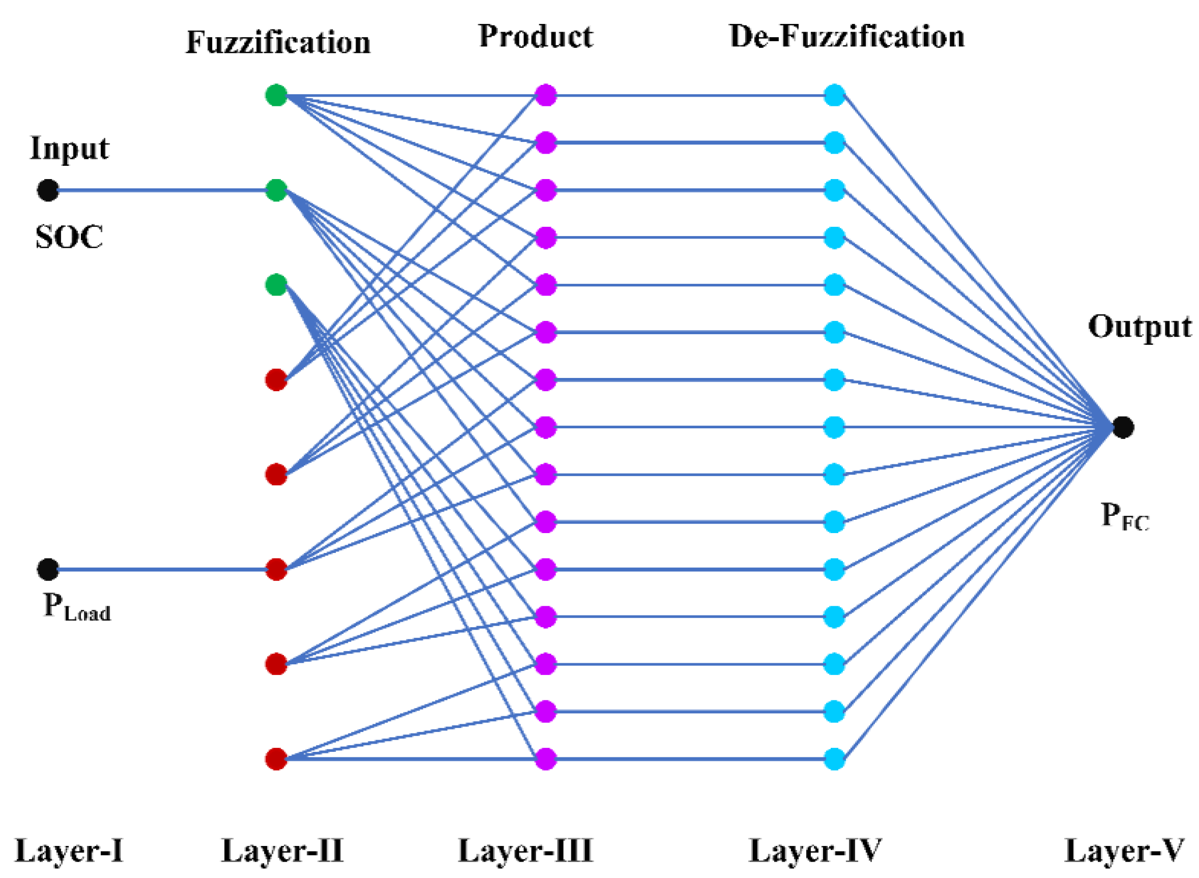
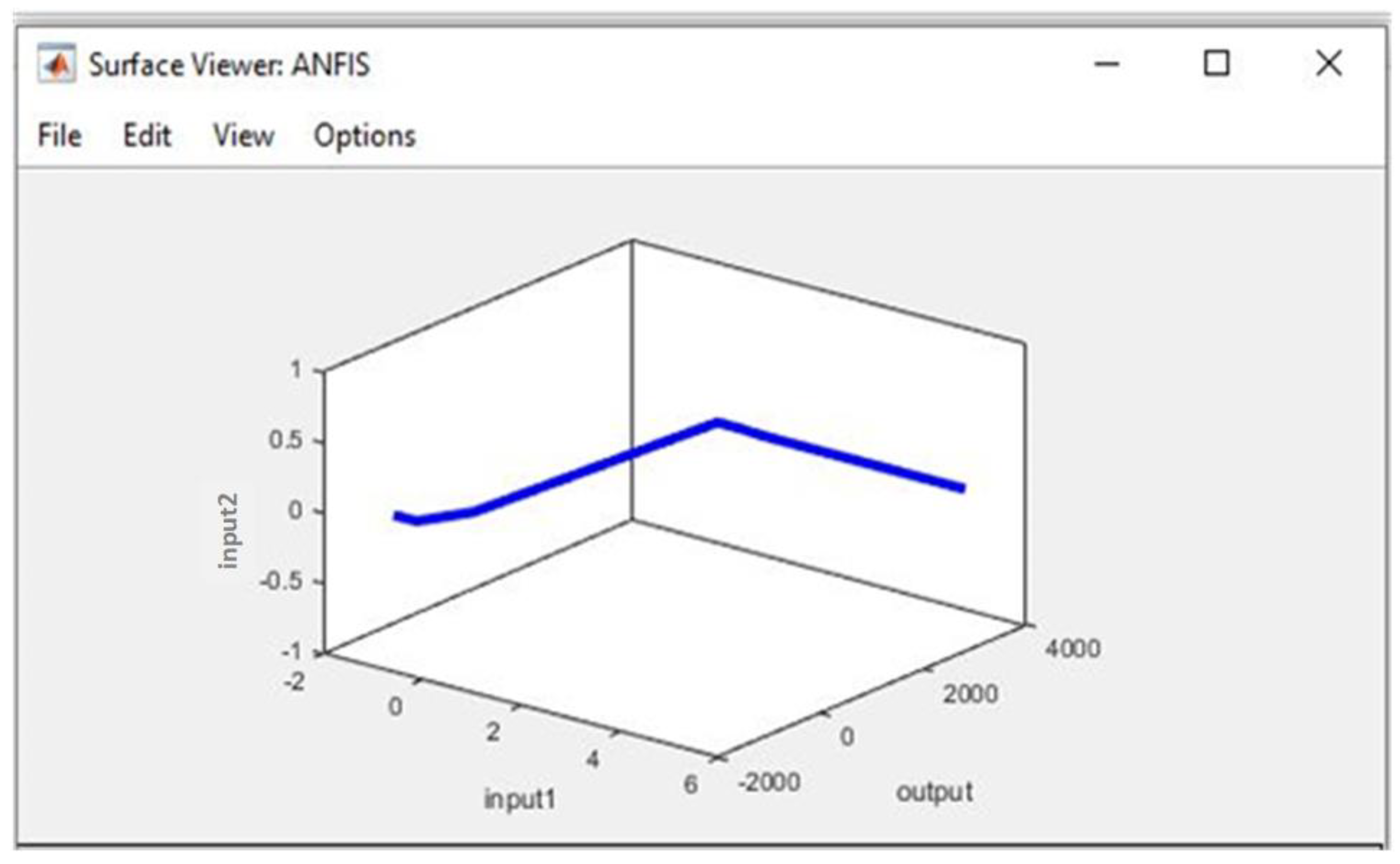
5.2. Adaptive Network-Based Fuzzy Interface System (ANFIS)

Power management methods have emerged for an automated learning experience to assist industrial uses such as fuzzy approaches, which are more common in system control. The ANFIS is a vital approach, which integrates both the artificial neural network (ANN)-based learning ability and also a rule-based fuzzy logic control technique based on inference capacity to build a full set over all different types of neural networks in the feed-forward type using a supervisory learning functionality [31,32]. The ANFIS strategy accomplishes a hybrid training process based on appropriate information and parameters of input/output and connections.
Figure 8 illustrates that the ANFIS architecture comprises a single hidden layer. Layer 1 indicates the input node, layer 2 comprises the fuzzification nodes, layer 3 comprises the result nodes (hidden), layer 4 comprises the defuzzification nodes and layer 5 represents the output node [33]. Furthermore, a node can be updated, and it will be classified as dynamic and static. Dynamic nodes include layers 2 and 4, whereas the stable nodes are layer 1 and layer 3. The ANFIS control technique uses the SoC of a Li-ion battery with three membership functions (MFs) and also utilizes the vehicle energy load, which is represented by Pload, as inputs to anticipate the fuel cell’s output power [34,35]. The ANFIS outcome is the estimated proportional gain from the PEMFC level. The ANFIS measures and adjusts the norms rapidly while using proportional variables.
Figure 9 illustrates the result region of the ANN approach: the label of the Z-axis is SoC, the X-axis is the load power (Pload) and the Y-axis is the fuel cell power (PFC). The purpose of adopting ANFIS, particularly for non-linear systems and networks that necessitate rapid selection in real time, is that the operation will be performed because of a learning result that has already been pre-obtained through an existing attempt. The genetic PMS can be adopted throughout the framework in airplanes, boats or automobiles, depending on the specific application. The PMS with a fuel cell and energy storage network (battery, UC) can also be used in planes, ships as well as electric vehicles, although the major objective of operating the PMS is a primary objective. The electric vehicles’ main criteria are durability and mitigating fuel consumption and enhancing the battery and UC usage. The EMS contains two parameters, which are illustrated in Figure 9. The first set of data are the SoC of the battery, which determines the battery capacity and wealth status. The optimal state is approximately 65 to 85% [36]. Another intention is to maintain the battery charging process (SoC within conventional ranges to prolong its duration). The power output of the vehicle might be the next EMS signal. To ensure operation stability, the maximum fuel cell capacity is constrained to 1–10 KW. The closed-loop management system of the ANN approach is derived from past expert data. The ANFIS training process determines the effectiveness of the output signal. ANFIS is conditioned to have the appropriate membership functions (MFs) throughout this environment by training samples across the state of charge, peak load and fuel cell energy, enabling the ANN model to estimate a linear relationship with endpoints (input and output).
The input/output samples’ specialized information is applied to enhance the control system’s performance with a minimal number of errors. To limit training problems, (1000) epochs are performed till the error rate is below 0.0001 for the training samples; this signifies the ANN-based output signal and is close to perfect. Figure 10 shows the flowchart of ANFIS training and testing.

5.3. Proposed Algorithm

The proposed algorithm is a hybridized algorithm (ECMS+ANFIS), and the flowchart is illustrated in Figure 11. It states a multi-objective PMS for the better reduction of hydrogen consumption as well as efficiency and with reduced stresses on hybrid sources when compared to PI, SMC, ECMS and EEMS.

5.3.1. Collection of Equivalent Factor Samples

The corresponding factors, as is widely known, are directly linked to the driving cycle information and system condition, and they play an important role in saving fuel. A continuous optimization technique may be used to derive the ideal equivalent component Sopt from the acquired control trajectory. The Smin and Smax bounds of the analogous factor are established. In the allowable range [Smin, Smax], S decreases and increases with optimal value of equivalent samples. with When the vehicle’s power demand is low, the cost of consuming electricity is smaller. The corresponding factor increases as the vehicle’s power requirement increases, indicating that the engine can produce more power. Whenever the battery’s state of charge (SoC) is lower, the greater corresponding factor is used. It indicates that the discharge tendency is inhibited, resulting in a reduction in the motor’s power output, preventing the batteries from over-discharging.

5.3.2. Optimal Control Trajectory Acquisition

A simultaneous hybrid electrical bus’s energy optimization is a non-linear optimization challenge with various restrictions. As explained previously, the optimization issue can be solved using a variety of techniques. The DP technique is used to resolve hard issues by utilizing recursion calculation, which does not depend on differential equations, to find the best power distribution in the hybrid engine. The entire optimization issue may be broken down into various simple subproblems in this work, such as constrained segments across time. Once all possible case changes with various control variables have been computed in each segment, the solution of each pathway and the associated cost will be noted. Following the completion of the above computation, the ideal solution may be found by minimizing an objective function. Due to precise gird points for both the state and the controlling vector, the globally optimum outcome is provided.

6. Results and Comparisons

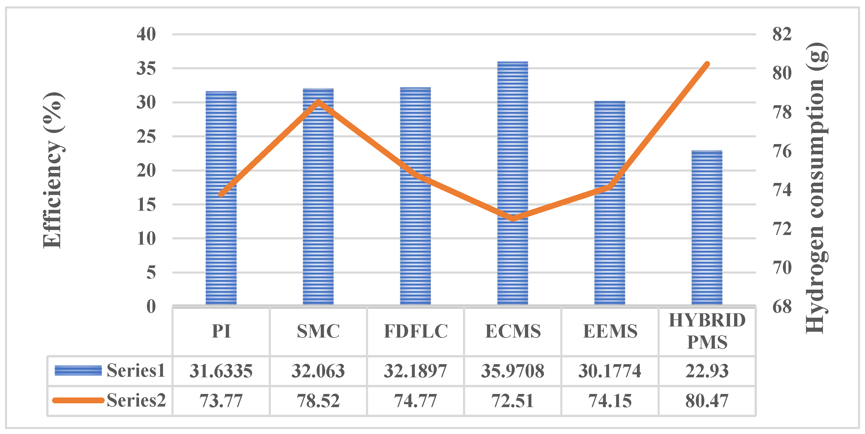
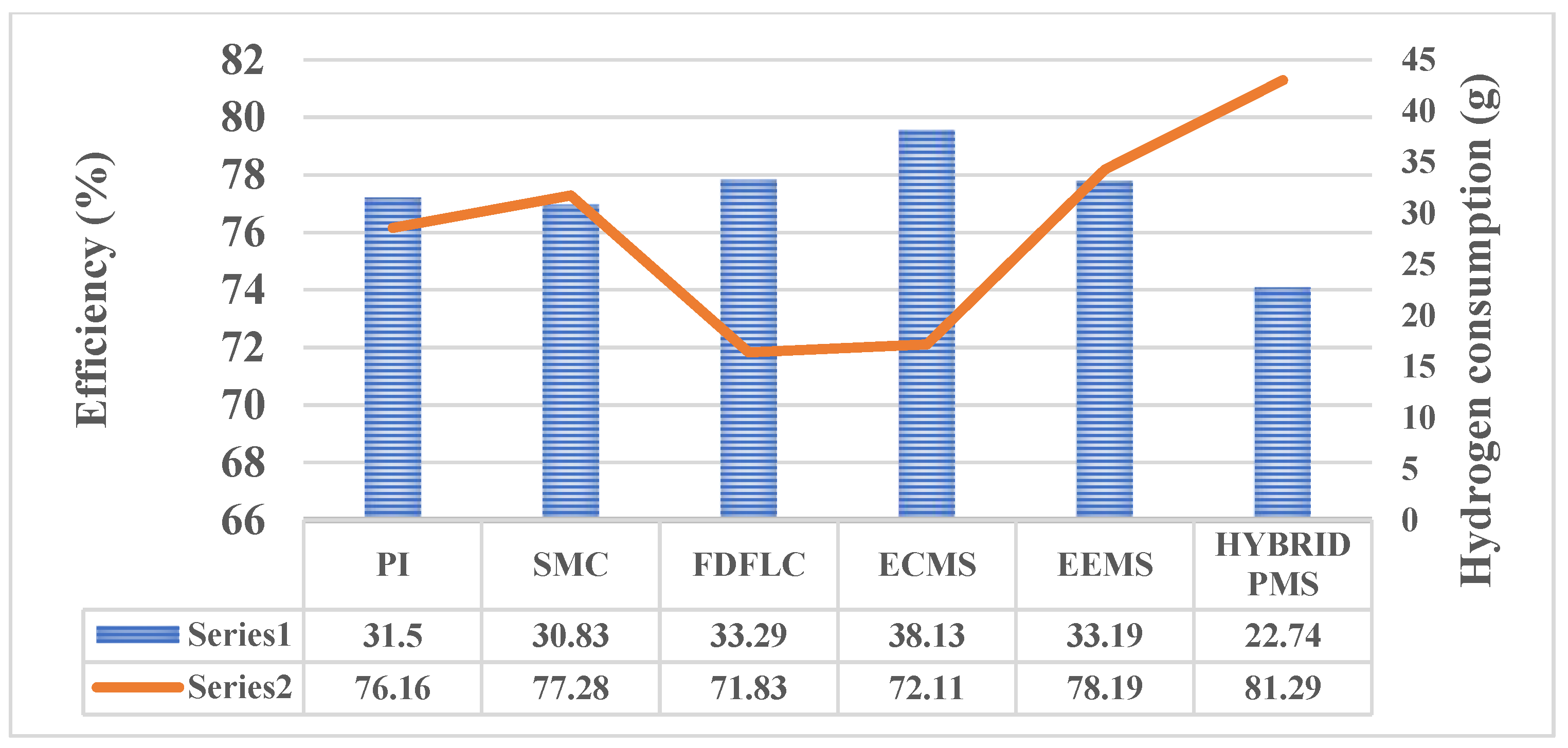
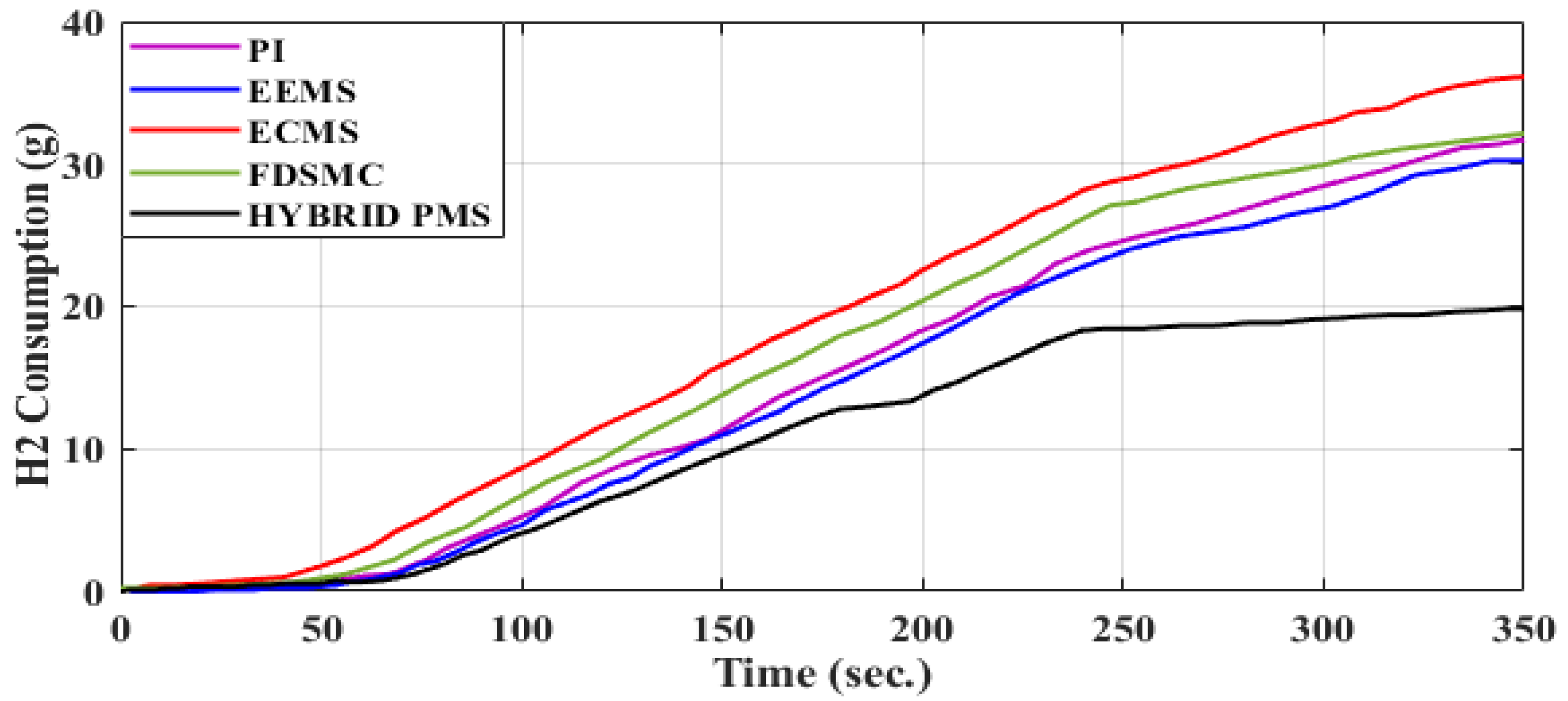
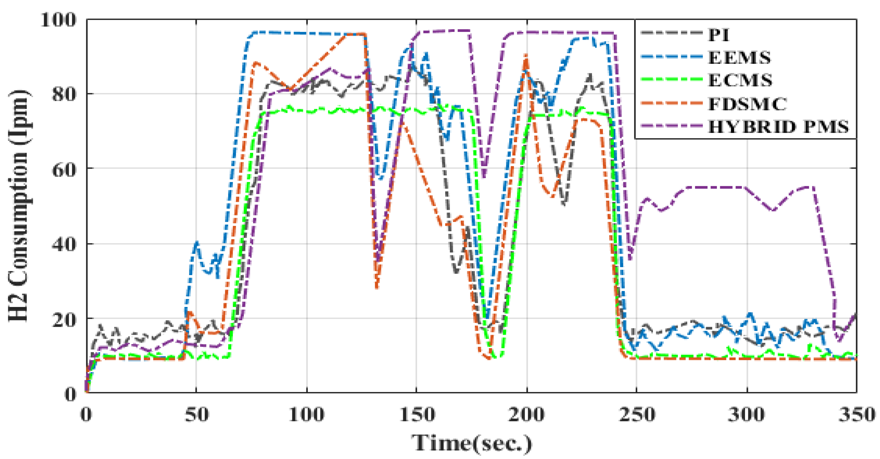
6.1. Hydrogen Consumption, Overall Efficiency and Stress Analysis

Different power managing methods for hybrid storage structures were implemented. Each power management scheme was implemented with the same initial conditions: state of charge of battery = 70%, temperature of battery = 30 , voltage of supercapacitor = 270 V, temperature of supercapacitor = 25 , voltage of fuel cell = 52 V, temperature of fuel cell = 40 . The model of FC/B/SC comprised 12.5 KW, 30–60 V PEMFC, a 48 V,40 Ah Li-ion battery and 15.6 F, 291.6 V-6 series-connected supercapacitors. The battery storage was controlled by two DC/DC converters. The converter operated for discharging the battery in a 4 KW boost mode and for charging the battery in a 1.2 KW buck mode. The comparison of the various power management strategies based on hydrogen consumption, overall efficiency and stress on the fuel cell, battery and supercapacitor is tabulated in Table 5. The consumption of hydrogen in (Ipm and grams), is illustrated in Figure 12 (HWFET—Drive Cycle) and Figure 13 (WLTP—Class 3 Drive Cycle) and Figure 14, Figure 15, Figure 16 and Figure 17, and the overall efficiency of all power management schemes was calculated. For the fuel cell, battery and supercapacitor energy, the stress assessment was performed using the Haar wavelet approach at 270 V DC. A wavelet toolbox is available in MATLAB. The power degradation in low-frequency and high-frequency apparatuses was evaluated via Haar wavelet decomposition. The component with a high frequency has a zero-mean value, and the standard deviation ( σ ) of this module provides a better insight into how a separate storage system is managed. The amount of hydrogen consumption used (in grams) is given as
  Cons H 2 = N F 0 1800 i fc ·   dt
Here, F = Faraday fundamental (A.s/mol).
Global efficiency is expressed as
Efficiency   ɳ % = P load P FC in + P batt in + P cap in .  
Here; P FC in , P batt in ,   P cap in = Power of FC/B/UC.

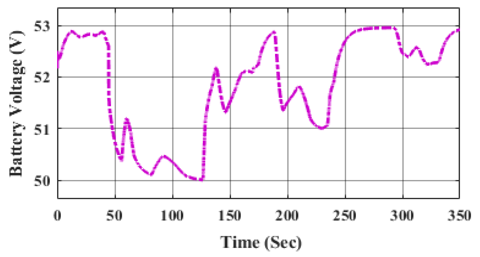
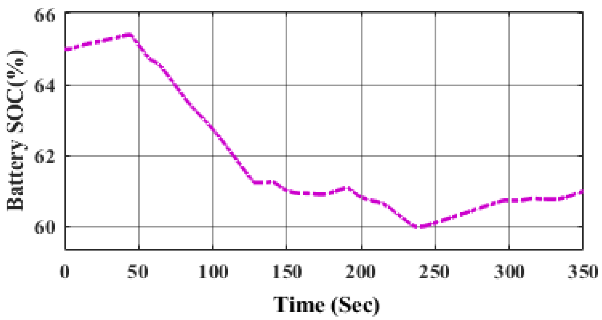
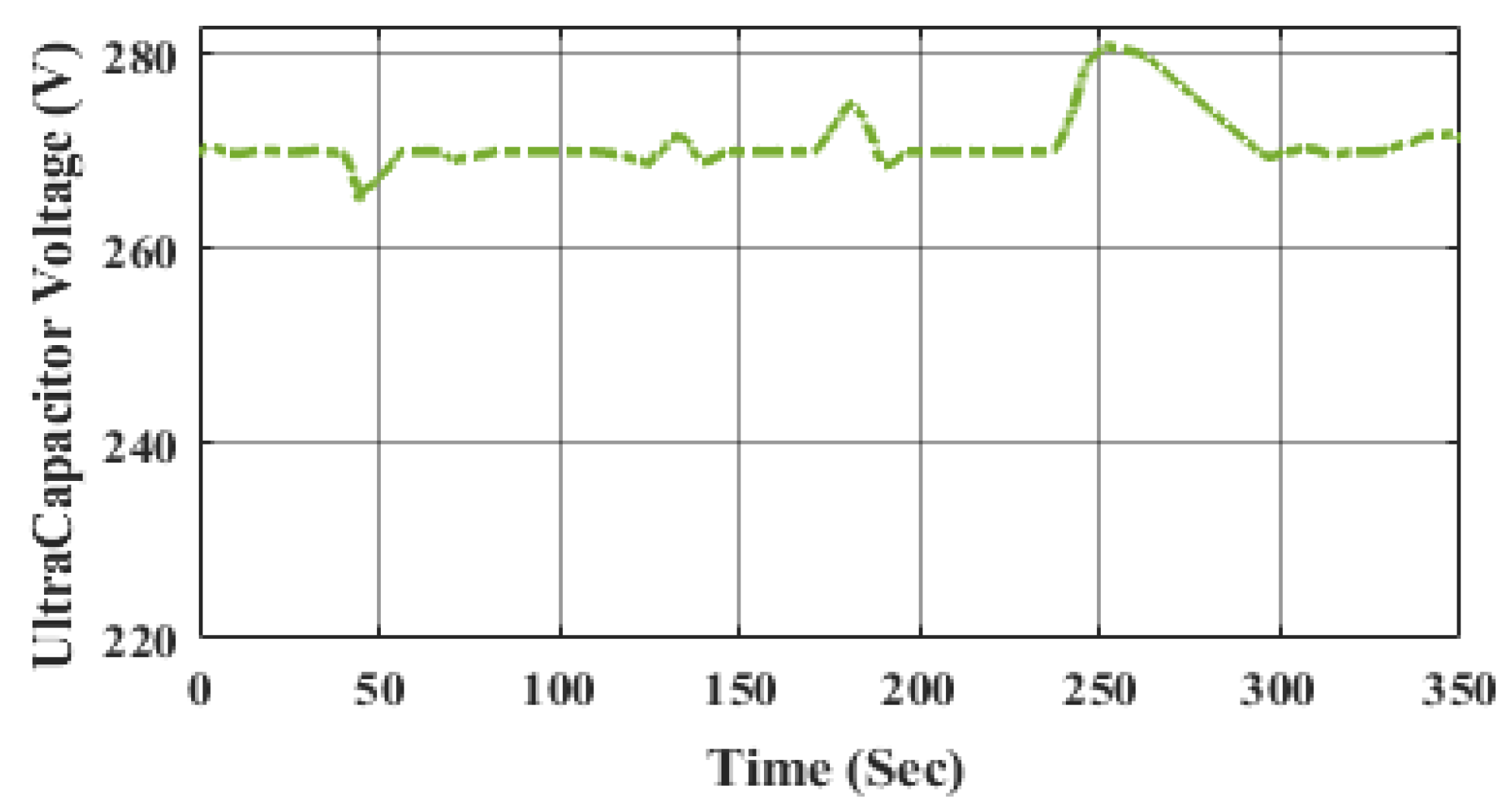
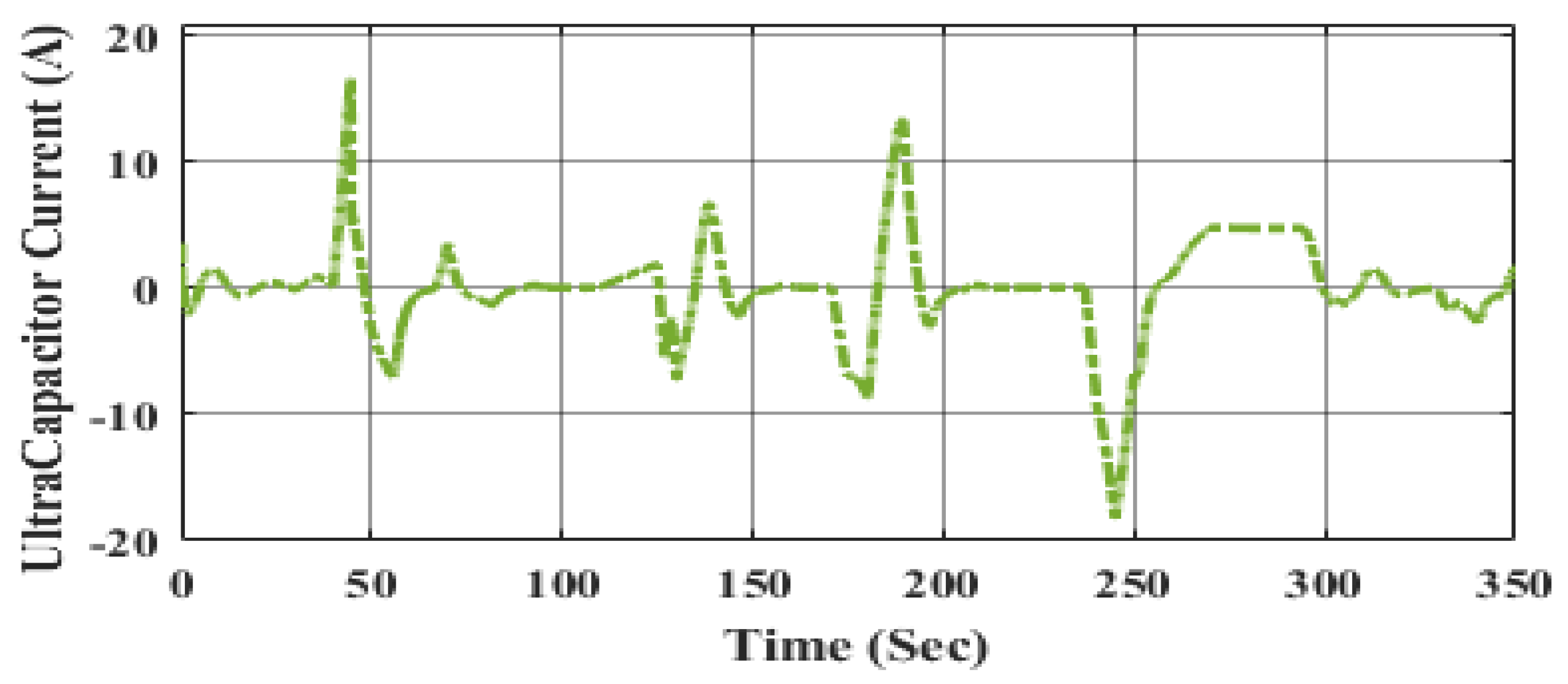
6.2. SoC of Battery and Supercapacitor Voltage

In the classic PI strategy, to attain the reference SoC, there is a faster discharging of the battery in which the load is controlled by the primary source—the fuel cell—and recharging the battery. In the case of state machine control, if the SoC of the Li-ion battery bank reaches its minimum limit, then the fuel cell charges the supercapacitors over their reference voltage (270 V), forcing the DC bus to regulate the charge of the batteries. Meanwhile, in the case of the frequency decoupling fuzzy logic strategy, constant power is supplied by the fuel cells, which allows the battery to recharge compared to other strategies. An equivalent consumption minimization scheme and external energy minimization scheme perform better because higher battery power is used. The variation in the fuel cell voltage and current is shown in Figure 18 and Figure 19.
The battery and UC’s time response plots are shown in Figure 20, Figure 21, Figure 22, Figure 23 and Figure 24. The Li-ion battery and UC’s states of charge are approximately the same, indicating that the system would be in a fully charged condition when the primary input is disconnected from the operation. The battery and UC currents are increased at this point. This means that the UC and batteries are being used to match the increasing load requirement, and their interface voltages are being decreased as a result. At the same time, the battery and UC circumstances are then modified as the load changes.
This means that the power supplied by both the battery bank and UC bank for supplying the required load is superior when compared to the power supplied by the FC, resulting in the lowest hydrogen consumption.

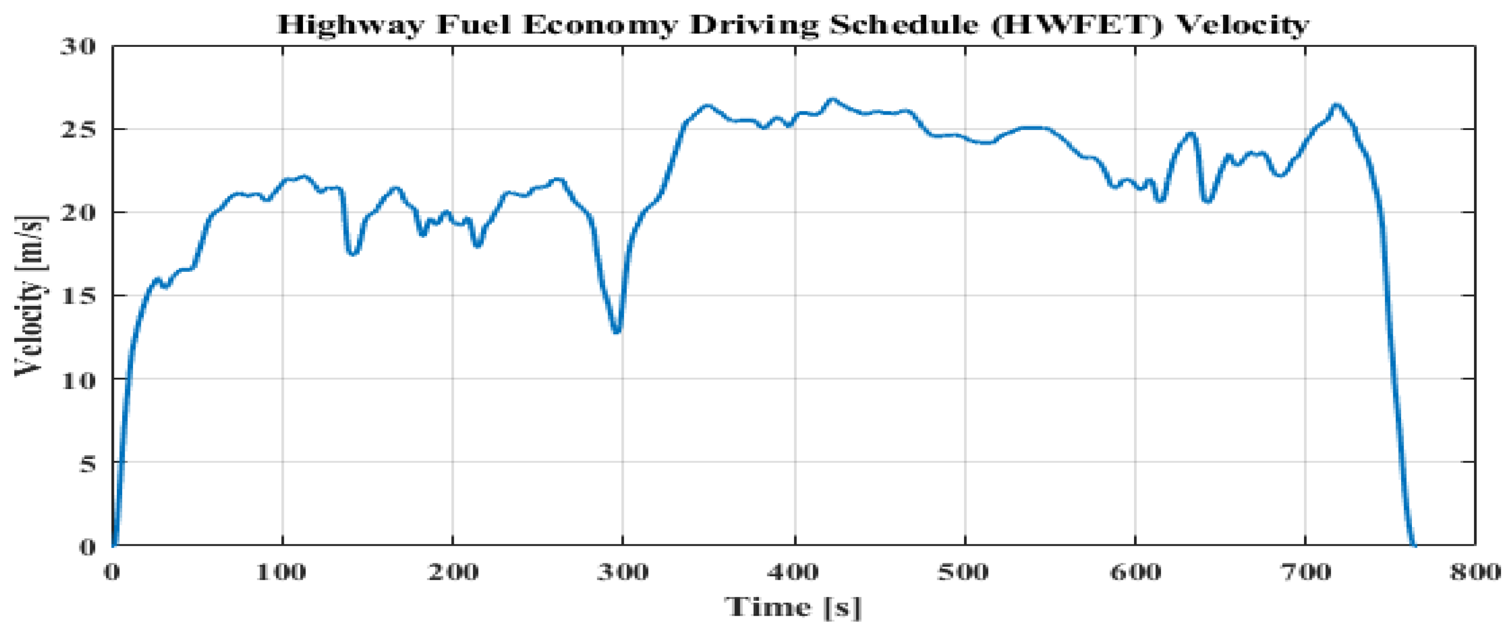
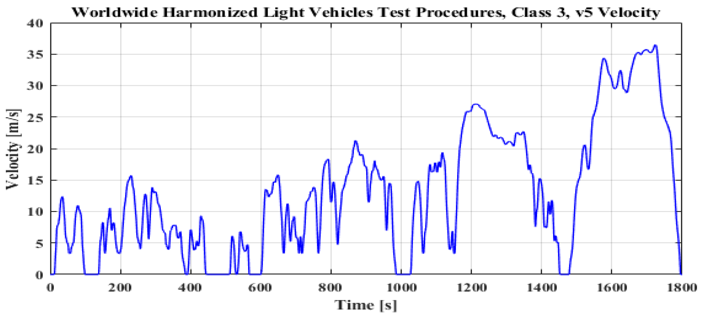
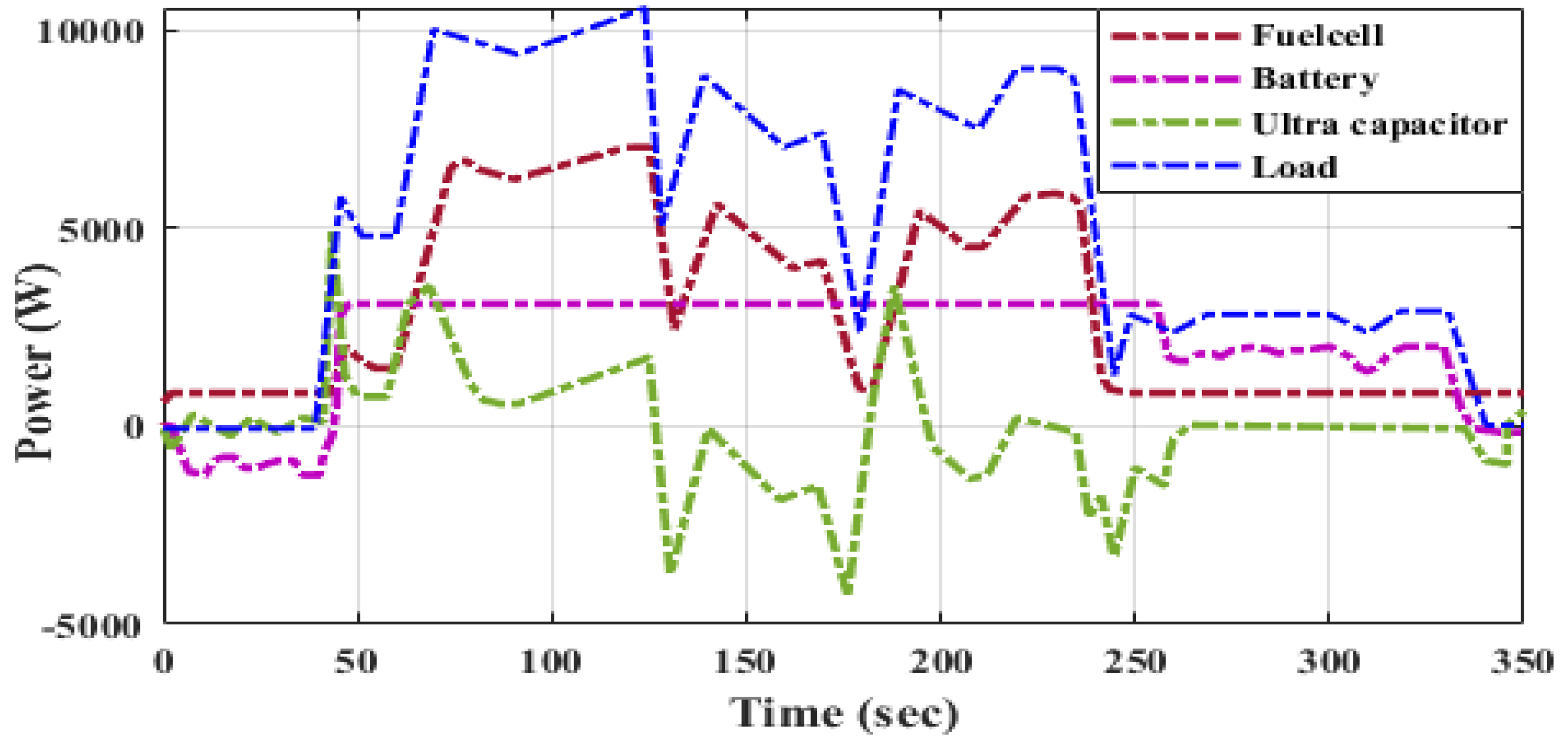
6.3. Distribution of Power to Load by Using Drive Cycle Data

The overall hybrid storage system is tested with the following drive cycles: HWFET and WLTC—Class 3.
  • Highway Fuel Economy Driving Schedule (HWFET—Drive Cycle)
Figure 25 illustrates the Highway Fuel Economy Test (HWFET or HFET) cycle, which is a vehicular dynamometer operating program designed by the United States Environmental Protection Agency (EPA) for determining the fuel economy of light-duty cars [40 CFR 600, Section B]. The HWFET is employed to calculate the vehicle fuel economy rating, whereas the FTP-75 is employed to obtain the urban fuel economy rating.
  • Worldwide Harmonized Light Vehicles Test procedures (WLTP–Class 3 Drive Cycle)
Shown in Figure 26, the Worldwide Harmonized Light Vehicle Test Cycles (WLTC) are automotive testing machine measurements used to evaluate energy consumption and emissions from light-duty cars. Class 3 represents automobiles operated in Europe as well as Japan, as it has the highest power-to-mass ratio. Class 3 vehicles are divided into two subclasses based on their higher speed: Class 3a with a maximum speed of 120 km/h and Class 3b with a maximum speed of 120 km/h.
A hybrid energy source (FC/B/UC) supplies the power to load, which is shown in Figure 27. During a period of time, a span of 350 s, regarding the performance of the system at t = 0, the system starts with no load demand, so load power is zero. Here, the battery is charged by the fuel cell. At the time of 40 s, there is a distribution of the power supply to the battery and supercapacitor, and also the power of the fuel cell increases gradually. Later, at 45 s, the level of supercapacitor voltage reduces to the 270 V reference value. At time t = 60 s, the power of the fuel cell rises predominantly, whereas the supercapacitor provides extra transient demand beyond the maximum power of the primary source. Thus, the secondary sources are charged by extra fuel cell power. At 330 s, there is a lower load demand; hence, the power of the primary source also reduces gradually while recharging the battery container; a comparison of each PMS is given in Table 5.

7. Conclusions

An ANFIS-based ECMS-integrated control strategy for power management in hybrid electric vehicles is proposed in this paper to conserve maximum fuel, with the main power source as a PEMFC and secondary sources as a battery bank (BB) and ultracapacitors (UC). The ECMS is a cost function-based optimization approach where the SoC of the battery is regulated by the penalty coefficients of battery power. The power of UC is overlooked in this optimization approach. The voltage profile of the DC bus is regulated by converters of the battery bank such that, once the UCs are drained, they are restored with the same power from the battery bank. The load demand is balanced via a battery and FC over a load cycle. The ANFIS-based controller efficiently monitors the fluctuating energy demand but also continues to maintain a DC bus voltage profile with a limited error signal as well as a rapid trackability level compared to that of a conventional control system. Since continuous monitoring enhances the battery’s lifespan, the performance of HEVs will be superior and more reliable. The performance analysis was conducted in terms of the consumption of hydrogen, SoC, global efficiency and stress on individual sources. The state machine control technique (SMC) attains an efficiency of 78.52%, and the stress ( σ ) on the supercapacitor and battery is 34.7 and 22.59. In the case of the frequency decoupling and fuzzy logic technique, the stress σ is 22.04 and the battery SoC is 70–57%, but there is moderate fuel consumption of 32.1897 (g) of H2 with an overall efficiency of 74.77%. Regarding the equivalent consumption minimization strategy (ECMS), there is higher stress (23.42) on fuel cells with an efficiency of 72.51%. Meanwhile, in the external energy maximization control technique (EEMS), there is the lowest fuel consumption of 30.1774 (g) of H2 and higher usage of the Li-ion battery, whose SOC is 70–59%, while the stress on the fuel cell is low. In the hybrid PMS, fuel consumption is 22.93 (g), with reduced stress ( σ ) on the fuel cell, which is 15.8.
For all the control strategies, the value of the DC link is maintained at around (270 VDC). Energy management in hybrid vehicles must adopt a multi-scheme EMS since each approach is chosen as per key variables. For instance, depending on the actual lifespan of the input sources, EMS can indeed be employed to optimize the source lifespan or reduce the stress on FC/B/UC. Further, ANFIS with ECMS has been validated across different drive cycles, i.e., HWFET and WLTC—Class 3.

Author Contributions

Conceptualization, V.M. and Y.P.O.; Supervision, Y.P.O.; Validation, V.M.; Visualization, V.M.; Writing–original draft, V.M. and Y.P.O.; Writing–review & editing, V.M. and Y.P.O. All authors have read and agreed to the published version of the manuscript.

Funding

This research received no external funding.

Institutional Review Board Statement

Not applicable.

Informed Consent Statement

Not applicable.

Data Availability Statement

Not applicable.

Conflicts of Interest

The authors declare no conflict of interest.

References

  1. Zhang, F.; Wang, L.; Coskun, S.; Pang, H.; Cui, Y.; Xi, J. Energy management strategies for hybrid electric vehicles: Review, classification, comparison, and outlook. Energies 2020, 13, 3352. [Google Scholar] [CrossRef]
  2. Duhr, P.; Christodoulou, G.; Balerna, C.; Salazar, M.; Cerofolini, A.; Onder, C.H. Time-optimal gearshift and energy management strategies for a hybrid electric race car. Appl. Energy 2021, 282, 115980. [Google Scholar] [CrossRef]
  3. Guo, N.; Zhang, X.; Zou, Y.; Guo, L.; Du, G. Real-time predictive energy management of plug-in hybrid electric vehicles for coordination of fuel economy and battery degradation. Energy 2021, 214, 119070. [Google Scholar] [CrossRef]
  4. Li, Q.; Chen, W.; Liu, S.; You, Z.; Tao, S.; Li, Y. Power management strategy based on adaptive neuro-fuzzy inference system for fuel cell-battery hybrid vehicle. J. Renew. Sustain. Energy 2012, 4, 013106. [Google Scholar] [CrossRef]
  5. Allahvirdizadeh, Y.; Mohamadian, M.; HaghiFam, M.R.; Hamidi, A. Optimization of a fuzzy-based energy management strategy for a PV/WT/FC hybrid renewable system. Int. J. Renew. Energy Res. 2017, 7, 1686–1699. [Google Scholar]
  6. Yavasoglu, H.A.; Tetik, Y.E.; Ozcan, H.G. Neural network-based energy management of multi-source (battery/UC/FC) powered electric vehicle. Int. J. Energy Res. 2020, 44, 12416–12429. [Google Scholar] [CrossRef]
  7. Montazeri-Gh, M.; Pourbafarani, Z. Near-optimal SOC trajectory for traffic-based adaptive PHEV control strategy. IEEE Trans. Veh. Technol. 2017, 66, 9753–9760. [Google Scholar] [CrossRef]
  8. Singh, K.V.; Bansal, H.O.; Singh, D. Development of an adaptive neuro—Fuzzy inference system–based equivalent consumption minimization strategy to improve fuel economy in hybrid electric vehicles. IET Electr. Syst. Transp. 2021, 11, 171–185. [Google Scholar] [CrossRef]
  9. Suhail, M.; Akhtar, I.; Kirmani, S.; Jameel, M. Development of progressive fuzzy logic and ANFIS control for energy management of plug-in hybrid electric vehicle. IEEE Access 2021, 9, 62219–62231. [Google Scholar] [CrossRef]
  10. Kamel, A.A.; Rezk, H.; Abdelkareem, M.A. Enhancing the operation of fuel cell-photovoltaic-battery-supercapacitor renewable system through a hybrid energy management strategy. Int. J. Hydrogen Energy 2021, 46, 6061–6075. [Google Scholar] [CrossRef]
  11. Song, Z.; Hofmann, H.; Li, J.; Hou, J.; Han, X.; Ouyang, M. Energy management strategies comparison for electric vehicles with a hybrid energy storage system. Appl. Energy 2014, 134, 321–331. [Google Scholar] [CrossRef]
  12. Gaber, M.; El-Banna, S.; El-Dabah, M.; Hamad, O. Designing and implementation of an intelligent energy management system for electric ship power system based on adaptive neuro-fuzzy inference system (ANFIS). Adv. Sci. Technol. Eng. Syst. J. 2021, 6, 195–203. [Google Scholar] [CrossRef]
  13. Tian, X.; He, R.; Xu, Y. Design of an energy management strategy for a parallel hybrid electric bus based on an IDP-ANFIS scheme. IEEE Access 2018, 6, 23806–23819. [Google Scholar] [CrossRef]
  14. Ding, N.; Prasad, K.; Lie, T.T. Design of a hybrid energy management system using designed rule-based control strategy and genetic algorithm for the series-parallel plug-in hybrid electric vehicle. Int. J. Energy Res. 2021, 45, 1627–1644. [Google Scholar] [CrossRef]
  15. Colvin, R. Advances in Automotive Technologies; Springer: Berlin/Heidelberg, Germany, 2019; Volume 84, ISBN 9789811559464. [Google Scholar]
  16. Zhang, X.; Guo, L.; Guo, N.; Zou, Y.; Du, G. Bi-level energy management of plug-in hybrid electric vehicles for fuel economy and battery lifetime with intelligent state-of-charge reference. J. Power Sources 2021, 481, 228798. [Google Scholar] [CrossRef]
  17. Cai, C.H.; Du, D.; Liu, Z.Y. Battery state-of-charge (SOC) estimation using adaptive neuro-fuzzy inference system (ANFIS). IEEE Int. Conf. Fuzzy Syst. 2003, 2, 1068–1073. [Google Scholar] [CrossRef]
  18. Shaik, R.B.; Kannappan, E.V. Application of adaptive neuro-fuzzy inference rule-based controller in hybrid electric vehicles. J. Electr. Eng. Technol. 2020, 15, 1937–1945. [Google Scholar] [CrossRef]
  19. Li, P.; Jiao, X.; Li, Y. Adaptive real-time energy management control strategy based on fuzzy inference system for plug-in hybrid electric vehicles. Control Eng. Pract. 2021, 107, 104703. [Google Scholar] [CrossRef]
  20. Karaboga, D.; Kaya, E. Adaptive network-based fuzzy inference system (ANFIS) training approaches: A comprehensive survey. Artif. Intell. Rev. 2019, 52, 2263–2293. [Google Scholar] [CrossRef]
  21. Zhang, F.; Hu, X.; Langari, R.; Wang, L.; Cui, Y.; Pang, H. Adaptive energy management in automated hybrid electric vehicles with flexible torque request. Energy 2021, 214, 118873. [Google Scholar] [CrossRef]
  22. Zhang, L.; Ye, X.; Xia, X.; Barzegar, F. A real-time energy management and speed controller for an electric vehicle powered by a hybrid energy storage system. IEEE Trans. Ind. Inform. 2020, 16, 6272–6280. [Google Scholar] [CrossRef]
  23. Zhang, Q.; Li, G. A predictive energy management system for hybrid energy storage systems in electric vehicles. Electr. Eng. 2019, 101, 759–770. [Google Scholar] [CrossRef]
  24. Zhang, Q. Applied sciences strategy for hybrid electric vehicles based on driving cycle recognition. Appl. Sci. 2020, 10, 696. [Google Scholar]
  25. Wieczorek, M.; Lewandowski, M. A mathematical representation of an energy management strategy for hybrid energy storage system in electric vehicle and real-time optimization using a genetic algorithm. Appl. Energy 2017, 192, 222–233. [Google Scholar] [CrossRef]
  26. Sarkar, J.; Bhattacharyya, S. Application of graphene and graphene-based materials in clean energy-related devices Minghui. Int. J. Energy Res. 2012, 33, 23–40. [Google Scholar] [CrossRef]
  27. Gomes, G.F.; da Cunha, S.S.; Ancelotti, A.C. A sunflower optimization (SFO) algorithm applied to damage identification on laminated composite plates. Eng. Comput. 2019, 35, 619–626. [Google Scholar] [CrossRef]
  28. Mirjalili, S.; Gandomi, A.H.; Mirjalili, S.Z.; Saremi, S.; Faris, H.; Mirjalili, S.M. Salp swarm algorithm: A bio-inspired optimizer for engineering design problems. Adv. Eng. Softw. 2017, 114, 163–191. [Google Scholar] [CrossRef]
  29. Mirjalili, S.; Mirjalili, S.M.; Hatamlou, A. Multi-verse optimizer: A nature-inspired algorithm for global optimization. Neural Comput. Appl. 2016, 27, 495–513. [Google Scholar] [CrossRef]
  30. Saremi, S.; Mirjalili, S.; Lewis, A. Grasshopper optimisation algorithm: Theory and application. Adv. Eng. Softw. 2017, 105, 30–47. [Google Scholar] [CrossRef] [Green Version]
  31. Mirjalili, S.; Mirjalili, S.M.; Lewis, A. Grey wolf optimizer. Adv. Eng. Softw. 2014, 69, 46–61. [Google Scholar] [CrossRef] [Green Version]
  32. Rezk, H.; Al-Oran, M.; Gomaa, M.R.; Tolba, M.A.; Fathy, A.; Abdelkareem, M.A.; Olabi, A.G.; El-Sayed, A.H.M. A novel statistical performance evaluation of most modern optimization-based global MPPT techniques for a partially shaded PV system. Renew. Sustain. Energy Rev. 2019, 115, 109372. [Google Scholar] [CrossRef]
  33. Abdalla, O.; Rezk, H.; Ahmed, E.M. Wind-driven optimization algorithm based global MPPT for PV system under non-uniform solar irradiance. Sol. Energy 2019, 180, 429–444. [Google Scholar] [CrossRef]
  34. Tolba, M.; Rezk, H.; Diab, A.A.Z.; Al-Dhaifallah, M. A novel robust methodology based salp swarm algorithm for allocation and capacity of renewable distributed generators on distribution grids. Energies 2018, 11, 2556. [Google Scholar] [CrossRef] [Green Version]
  35. Yadav, N.; Yadav, A.; Bansal, J.C.; Deep, K.; Kim, J.H. Harmony Search and Nature Inspired Optimization Algorithms: Theory and Applications, ICHSA 2018; Springer: Berlin/Heidelberg, Germany, 2019; Volume 741, ISBN 9789811307607. [Google Scholar]
  36. Mirjalili, S. Particle swarm optimization. Stud. Comput. Intell. 2019, 780, 15–31. [Google Scholar] [CrossRef]
Figure 1. Configuration of energy management in a hybrid electric vehicle.
Energies 15 04185 g001
Figure 2. Classical PI control method.
Energies 15 04185 g002
Figure 3. State machine control technique.
Energies 15 04185 g003
Figure 4. State machine control hysteresis.
Energies 15 04185 g004
Figure 5. Frequency decoupling and fuzzy logic control technique.
Energies 15 04185 g005
Figure 6. External energy maximization scheme.
Energies 15 04185 g006
Figure 7. Equivalent consumption minimization method.
Energies 15 04185 g007
Figure 8. Structure of ANFIS.
Energies 15 04185 g008
Figure 9. The MATLAB simulation output surface of the ANFIS.
Energies 15 04185 g009
Figure 10. The procedure flowchart of ANFIS.
Energies 15 04185 g010
Figure 11. Flowchart of hybrid power management scheme (HPMS).
Energies 15 04185 g011
Figure 12. System efficiency and hydrogen consumption for each scheme (HWFET—Drive Cycle).
Energies 15 04185 g012
Figure 13. System efficiency and hydrogen consumption for each scheme (WLTP—Class 3 Drive Cycle).
Energies 15 04185 g013
Figure 14. Hydrogen consumption in grams for studied approaches (HWFET—Drive Cycle).
Energies 15 04185 g014
Figure 15. Hydrogen consumption in Ipm for studied approaches (HWFET—Drive Cycle).
Energies 15 04185 g015
Figure 16. Hydrogen consumption in grams for studied approaches (WLTP—Class 3 Drive Cycle).
Energies 15 04185 g016
Figure 17. Hydrogen consumption in Ipm for studied approaches (WLTP—Class 3 Drive Cycle).
Energies 15 04185 g017
Figure 18. Variation in fuel cell input voltage.
Energies 15 04185 g018
Figure 19. Variation in fuel cell input current.
Energies 15 04185 g019
Figure 20. Battery voltage–time response.
Energies 15 04185 g020
Figure 21. Time response of battery current.
Energies 15 04185 g021
Figure 22. Time response of battery state of charge (SoC).
Energies 15 04185 g022
Figure 23. Time response of ultracapacitor voltage.
Energies 15 04185 g023
Figure 24. Responses of ultracapacitor current.
Energies 15 04185 g024
Figure 25. Drive cycle data—HWFET.
Energies 15 04185 g025
Figure 26. Drive cycle data—WLTC (Class 3).
Energies 15 04185 g026
Figure 27. Power of hybrid sources (fuel cell, Li-ion battery and ultracapacitor) delivering the load request versus time.
Energies 15 04185 g027
Table 1. Specifications of a fuel cell.
Fuel Cell Model Input ParametersSpecifications
Voltage52.5 V
Number of fuel cells65
Nominal efficiency of the fuel stack50%
Operating temperature45 °C
Nominal supply pressure1.16 fuel (bar),1 air (bar)
Nominal composition (%)
[H2, O2, H2O (Air)]
99% H2, 95% O2, 21% H2O (air)
Response time of fuel cell voltage1 s
Peak utilization of O260%
Voltage undershoot2 V
Table 2. Specifications of supercapacitors.
Supercapacitor Model Input ParametersSpecifications
Surge voltage307 V
Capacitor number in series6
Capacitor count in parallel1
Rated voltage291.6 V
DC series resistance equivalent0.15 ohms
Rated capacitance15.6 F
Molecular radius 0.4 × 10 9 m
Operating temperature 25 °C
Table 3. Specifications of Li-ion battery.
Input Parameters for the Battery ModelSpecifications
Minimal voltage48 V
Esteemed capacity40 Ah
Determined capacity40 Ah
Fully charged voltage56.88 V
Minimal discharge current17.4 A
Internal resistance0.012 ohms
Nominal voltage capacity36.25 Ah
Exponential region52.3 Volts, 1.96 Ah
Response time of battery voltage30 s
Table 4. Power management design requirements.
Requirements of Power Management Strategies
Fuel cell power [Pfcmin–Pfcmax]1–10 KW
Battery power [Pbattmin–Pbattmax]−1.2–4 KW
State of charge of battery [SoC min–SoC max]60–90%
DC bus voltage [Vdcmin–Vdcmax]250–280 V
Maximum slope of fuel cell current40 A/S
Table 5. Overall performance of each PMS scheme.
Drive
Cycle
Criteria for PMSPISMCFDFCECMSEEMSANFIS-Based ECMS
HWFET
(Highway Fuel Economy Test Cycle)
State of charge of the
battery (%)
70–5170–5470.5470–5470–5970–58
Consumption of H2 (g)31.6332.0632.9735.9730.1722.93
Overall efficiency (%)73.7778.5274.7772.5174.1580.47
Stress   on   battery   ( σ ) 2221.9124.624.622.423.7
Stress   on   fuel   cell   ( σ ) 20.4222.5922.0423.4218.615.8
Stress   on   ultracapacitor   ( σ ) 35.9234.737.8437.8435.936.76
WLTC (Worldwide Harmonized Light Vehicle Test Cycles)State of charge of the
battery (%)
70–5270–5470.5370–5370–5970–59
Consumption of H2 (g)31.530.8333.2938.1333.1922.74
Overall efficiency (%)76.1677.2871.8372.1178.1981.29
Stress   on   battery   ( σ ) 2824.8127.929.424.4624.38
Stress   on   fuel   cell   ( σ ) 24.2323.1921.8427.1719.2319.82
Stress   on   ultracapacitor   ( σ ) 36.1232.4531.9334.9237.131.15
Publisher’s Note: MDPI stays neutral with regard to jurisdictional claims in published maps and institutional affiliations.

