Article

Thermal—Airflow Coupling in Hourly Energy Simulation of a Building with Natural Stack Ventilation

Department of Power Systems and Environmental Protection Facilities, Faculty of Mechanical Engineering and Robotics, AGH University of Science and Technology, Mickiewicza 30, 30-059 Krakow, Poland
Energies 2022, 15(11), 4175; https://doi.org/10.3390/en15114175
Submission received: 18 April 2022 / Revised: 30 May 2022 / Accepted: 2 June 2022 / Published: 6 June 2022

Abstract

:
Natural ventilation dominates in Polish residential buildings. It is a simple and low-cost system but its performance is affected by varying environmental conditions. Hence, setting up constant ventilation airflow results in errors when calculating heating and cooling energy. In this paper, an attempt to integrate the buoyancy effect in natural ventilation of a residential building at hourly resolution with the hourly simulation method of EN ISO 13790 to obtain energy use for space heating and cooling is presented. The ping-pong coupling algorithm was proposed and applied. Hourly variation of ventilation airflow rate was from −26.8 m3/h (flow from outdoor to the interior of the building) to 87.2 m3/h with 55 m3/h on average. The lack of a cooling system resulted in overheating during summer and indicated the necessity of its application or use of other techniques to reduce solar gains. Application of the cooling system resulted in an hourly ventilation rate from −38.0 m3/h to 87.2 m3/h. Detailed simulation in EnergyPlus and statistical analysis proved the applicability of the proposed method in stack-induced ventilation assessment. The coefficient of determination R2 = 0.936, mean squared error MAE = 5.72 m3/h and root mean square error RMSE = 7.86 m3/h.

1. Introduction

Regardless of the building’s energy standard, an important element in its thermal balance is heat for heating (in the cool season) or cooling (in the warm season) of the ventilation air [1,2,3,4]. It is so because of hygienic reasons: continuous operation of ventilation, providing fresh outdoor air and removing polluted indoor air, is necessary during the presence of people.
Due to significant energy consumption by buildings and rising energy costs, numerous efficiency-related initiatives have been launched in many countries recently [5,6,7]. Additionally, new building codes directed to reduce transmission losses through external partitions have been introduced [8,9,10]. Consequently, the importance of proper assessment of ventilation heat loss has increased [11,12].
The ventilation systems are divided into [13] natural ventilation (NV), mechanical ventilation (MV) and hybrid ventilation (HV). The first solution, because of low investment costs and simplicity [14], is preferred in residential buildings.
According to the results of the National Census of Population and Housing from 2011 [15], residential buildings form the most significant part of the Polish buildings stock. Of them [16] only 16% are the objects built after the year 2002. In addition, only 5.5% of multifamily buildings retrofitted between 2010 and 2016 had the ventilation system modernised [17]. It follows from this that, among various ventilation systems, natural ventilation plays the most important role in the Polish residential sector. Therefore, the problem of assessment of ventilation heat loss in total energy consumed for heating and cooling of buildings is of great practical importance.
In general, the calculation, measurement and hybrid methods are used in the energy evaluation of buildings [18,19,20,21]. The first type is the most commonly used because of its advantages [22]. Additionally, if properly calibrated based on in-situ measurements, simulation methods can produce very reliable results [23].
As ventilation airflow in a building depends on ambient and geometric conditions, in the first group of studies the computational fluid dynamics (CFD) simulation tools were involved to assess indoor thermal comfort, pollution transport, air distribution or input boundary conditions for energy simulations in naturally ventilated objects.
Malkawi et al. [24] presented an assessment of cooling energy consumption in a residential building with mixed ventilation. The FloVENT and FlowDesigner programs were used in CFD simulations of natural ventilation and Airflow Network, the built-in module of EnergyPlus, for mixed-mode ventilation. The authors concluded that Airflow Network could not deal with complex airflow issues which resulted in differences in flow rate predictions in relation to CFD tools. On the other hand, about 30–40 CFD simulations for a one-year study on mixed-mode natural ventilation are required.
A similar combination of tools was used in [25] to obtain boundary conditions on the building’s facade pressure (CFD), predict the natural ventilation’s potential and assess the effect of the selected windows opening positions (Rhinoceros 3D) on the energy demand of the three-story building (EnergyPlus).
In [26] authors linked 3D parametric modeling and CFD to assess wind-driven natural ventilation in a residential test building. The Rhinoceros tool was used for the geometric model and OpenFOAM for CFD simulations.
CFD application in naturally ventilated buildings was also presented for offices [27] and industrial facilities [28]. These programs can easily cope with the thermal-airflow coupled computations. Such coupling also occurs in the analysed case as buoyancy-induced ventilation airflow depends on the difference between ambient air and indoor air temperatures. At the same time, the indoor temperature depends on indoor thermal conditions influenced by the amount of ventilation air entering a building’s zone. This way an airflow-thermal coupling is established. The main four types of algorithms used to solve such couplings are distinguished in literature: the sequential method, ping-pong method, onion method and fully integrated method [29,30,31,32,33].
However, as CFD modelling is rather laborious, time-consuming, and requires the use of sophisticated commercial tools, it is preferred in the design studies rather than in energy assessment of buildings. For this purpose, building simulation tools, such as TRNSYS [34] or EnergyPlus [35,36,37,38] but also Autodesk Green Building Studio [39], IDA ICE [23], Matlab, DesignBuilder, Revit and Python [40], involving the aforementioned coupling methods, are preferred.
On the other hand, when the problem of fast energy calculations for certification, auditing or design purposes arises, then the related standards shall be used [41,42,43]. In such a case EN 13790 [44] or its recently introduced successor EN ISO 52016 [45] are recommended.
In [46] authors studied the use of the natural ventilation in a residential house in terms of a comfortable indoor environment and energy performance in the most efficient way in the early building design stage. CFD simulation was used to choose the most suitable architectural solution in terms of natural ventilation performance and indoor thermal comfort at the design stage of a residential building. Then, energy effects were evaluated using the monthly quasi-steady-state calculation method of EN ISO 13790.
In the study [47] on the energy efficiency of a residential multifamily building in Poland, annual heating energy was calculated for 180 building variants, including three types of ventilation (exhaust, exhaust with night reduction and mechanical ventilation with heat recovery). A monthly method from EN ISO 52016-1, similar to that of EN ISO 13790, was used.
A constant ventilation rate was commonly assumed to be sufficient to provide acceptable indoor air conditions for average users [48] in works using both monthly [49,50,51] and detailed methods applying various tools, such as EnergyPlus [52,53], TRNSYS [54] or Design Builder [55,56].
This assumption is satisfactory in practice in pre-design studies in energy auditing or in the fast evaluation of retrofit strategies where standard calculations are often required. In step-ahead studies, regarding a more detailed assessment of thermal dynamics, the inclusion of time variation of a ventilation flow is also needed. It depends on environmental conditions, especially air temperature and wind velocity [57,58]. For these reasons, monthly methods are not suitable here and dynamic methods have been used recently to model varying airflow in buildings with natural ventilation: COMIS [59], TRNSYS [60], EnergyPlus [61] and Matlab [62]. These tools are of high quality but they are too complicated or expensive for use in less demanding applications. For these reasons, intermediate solutions are sought that take account of current standards and are quick to implement.
Jędrzejuk and Rucińska [63] proposed an interesting simple and efficient solution that could be applied here. In their analysis of artificial cooling in a single family building, they used the 5R1C model of a building from EN ISO 13790.
This model has several advantages, such as easy modification for various applications [64,65,66] and low computational requirements [67,68,69]. It can be also easily applied in a spreadsheet [70,71] not requiring specialised commercial simulation tools. Despite its simplicity, it produces reliable results [72]. For these reasons, it was used in studies where varying ventilation flow was considered, such as broiler house [73], residential building [74], greenhouse [75] or building-façade with integrated solar thermal collectors [76].
Because of its flexibility, the 5R1C model was also adopted in simulations related to ventilation. Narowski et al. [77] separated infiltration and ventilation airflows using two separate thermal conductances. The resulting 6R1C model was solved in a spreadsheet but the calculation procedure was more complicated than in the case of the generic 5R1C model.
Michalak [78] proposed the 4R1C model with equivalent ventilation heat flux. It was calculated from the difference between outdoor and indoor temperatures. To overcome circular references during computations in the developed method he proposed the internal air temperature at the given time step to be taken from the previous one. The model was successfully validated against EN 15265, BESTEST and EnergyPlus simulation with varying, ventilation-induced, airflow.
This review shows the lack of applications of simple hourly dynamic models used in energy performance evaluation of buildings in simulations with natural stack ventilation systems. Mainly, sophisticated CFD or building performance simulation tools are used for these solutions. Therefore, the novelty of the paper comes directly from these considerations. Its aim is to describe an application of the 5R1C dynamic model in the simulation of heating and cooling demand in hourly resolution including the effect of buoyancy-driven natural ventilation. The usability of the proposed solution is confirmed by comparison with a more advanced tool.
The next section briefly presents a calculation of an airflow rate in buoyancy-driven ventilation, the 5R1C resistance-capacitance model of a building from EN ISO 13790 and a mathematical model to obtain stack-induced ventilation airflow. Then, the test building, weather data and simulation assumptions are given. After them, the results are presented, and concluding remarks are given.

2. Materials and Methods

2.1. Modelling of Natural Ventilation

Two types of natural ventilation are met in buildings. Wind-driven ventilation is caused by the different pressures created by the wind on a building’s envelope and by openings on the perimeter forming a flow path for ventilation air. Buoyancy-driven ventilation is based on differences between the density of warmer indoor and colder outdoor air, resulting in a flow of indoor air from a building’s interior through higher located openings. At the same time, cooler and denser outdoor air flows into a building through inlet openings [79,80,81,82].
The physical nature of natural ventilation makes it very difficult to model [36]. However, numerous experimental and theoretical studies conducted in recent decades have led to convenient mathematical relationships used to compute ventilation airflow in various conditions and technical solutions met in residential buildings.
As Poland lies in the heating-dominant climate, when the difference between indoor and outdoor temperature is larger than during the remaining periods of the year, the buoyancy effect dominates over the wind effect. Therefore, in Polish residential buildings, both single and multifamily, stack ventilation dominates [83]. Several experiments carried out in Poland [84,85] confirmed that during winds with low velocity the air change rate (ACH) resulting from the stack effect slightly exceeded the required standard minimum value. For these reasons and to simplify presented considerations, only the buoyancy effect was taken into account.
In the case of buoyancy-driven ventilation in a building with two openings: top Atop and bottom Abottom the ventilation airflow rate is given by the relationship [86,87]:
q ve = C d A eff gh T i T e T i ,
where Aeff is the effective opening area, given by:
A eff = A bottom 2 = A top 2
and Cd is the discharge coefficient (a typical value is 0.6), g is gravitational acceleration, h is the height between openings, and Ti and Te are internal and external temperatures, respectively.

2.2. The 5R1C Model

The EN ISO 13790 standard introduced the thermal network model of a building zone consisting of five thermal resistances and one capacitance (Figure 1).
The external envelope of a building is represented by two kinds of partitions. Thermally “light” elements (doors, windows, curtain walls, glazed walls, etc.) are described by the Htr,w thermal transmission coefficient. Thermally “heavy” elements (walls, ceilings) are included in the Htr,op thermal transmission coefficient. It is then split into the external (Htr,em) and the internal (Htr,ms) parts:
H tr , em = 1 / ( 1 / H tr , op 1 / H tr , ms )
with:
H tr , ms = h ms A m .
The single capacitor, Cm, represents the thermal mass of the building. The external environment is represented by two variables. The first one, external air temperature (Te) is connected with Htr,w and Htr,em coefficients. The supply air temperature (Tsup) is connected through the heat transfer by ventilation (Hve) with the internal air temperature (Ti). In the case of natural ventilation:
T sup = T e .
The indoor air node (Ti) and the central node (Ts) are linked through the coupling conductance Htr,is given by Equation:
H tr , is = h is A t .
The heat fluxes from internal heat sources (φint) and solar irradiance (φsol) are split into three parts: φia, φst, and φm, respectively, connected to the indoor air, the central node, and the thermal mass temperature nodes. Heating or cooling power (φHC) is supplied to (heating) or extracted from (cooling) the indoor air node.

2.3. The Calculation Algorithm

In this paper, the ping-pong coupling method (called also loose coupling, quasi-dynamic or decoupled approach) was used. In this approach, the thermal and the airflow models are run in sequence. At a given time step the output from the airflow model is passed to the thermal model. Then, the thermal model returns its output to the input of the airflow model at a subsequent time step.
In the considered model the ventilation heat transfer coefficient is computed from the relationship:
H ve = ϱ a c a q ve ,
with the volumetric heat capacity of air assumed to be constant at ρaca = 1200 J/m3K according to EN ISO 13790.
Inserting Equation (1) into Equation (7) we get:
H ve = ϱ a c a A C d gH T i T e T i .
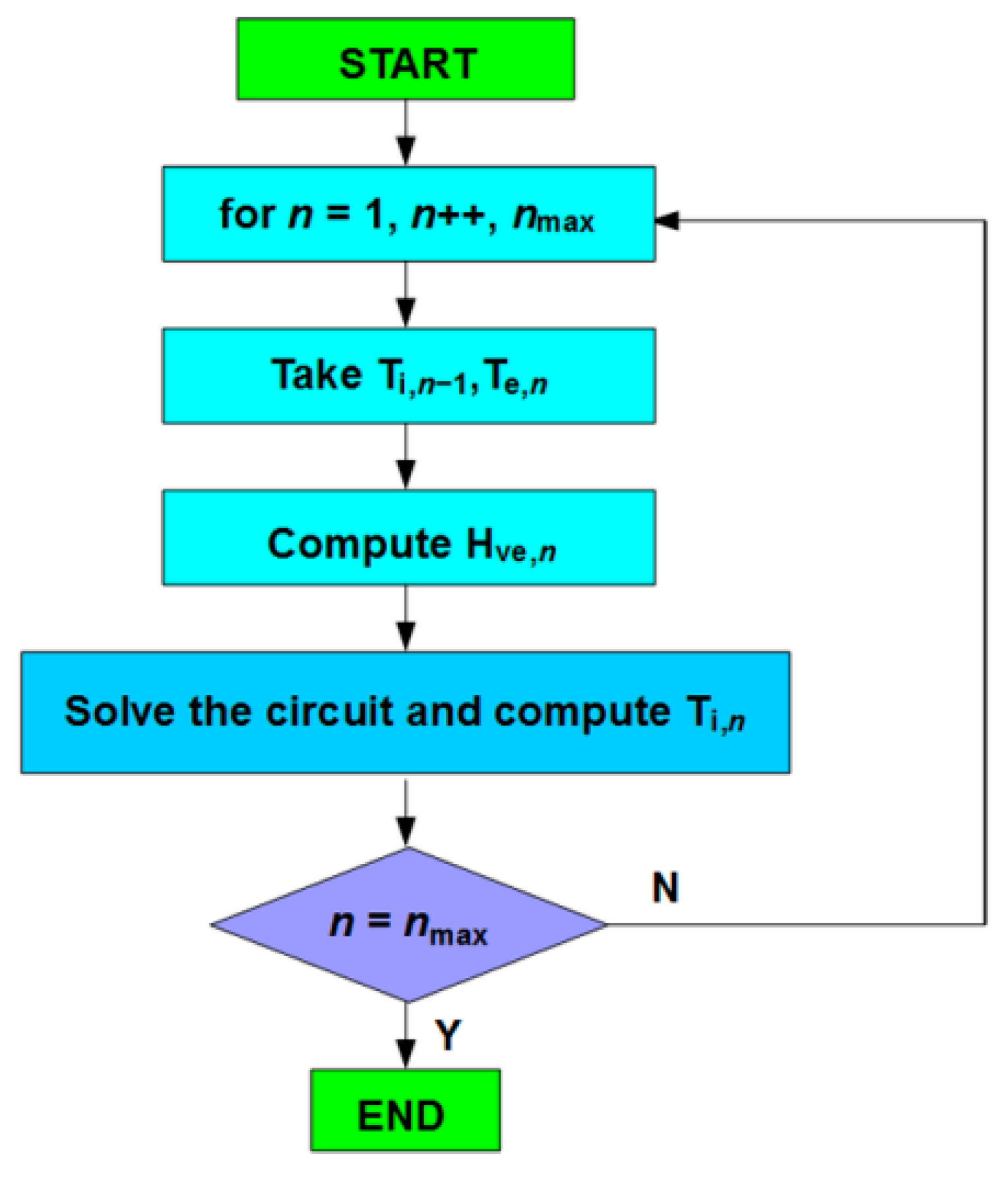
Taking into account the aforementioned considerations, we get the calculation algorithm of hourly heating and cooling energy demand presented in Figure 2.
At the first time step (n = 1) there should be assumed indoor air temperature from the previous, initial step. As it is unknown, it can be assumed as the set internal air temperature for heating, Tint,H,set or for cooling, Tint,C,set if calculations start in the heating or cooling period, respectively. As simulations are usually performed in hourly time step for the whole year, the step number, n, changes sequentially from 1 to 8760.
As the ventilation rate is computed by taking the indoor air temperature from the previous step it may be stated here that no convergence is reached at the end of each calculation step. It is not so because the required thermal power is calculated to obtain a set internal air temperature. Additionally, it should be remembered that indoor air temperature fluctuations are relatively small when compared to ambient air. It is so, especially during the heating period when the indoor-outdoor difference is the largest and the resulting stack effect is the most significant.
The block “Solve the circuit and compute Ti” contains the procedure to obtain heating or cooling power (φHC) required to maintain a certain set-point indoor air temperature. This procedure starts from the calculation of internal (φint) and solar (φsol) heat gains. Then they are split into three parts, as follows:
ϕ ia = 0.5 ϕ int ,
ϕ m = A m A t ( 0.5 ϕ int + ϕ sol ) ,
ϕ st = ( 1 A m A t H tr , w 9.1 A t ) ( 0.5 ϕ int + ϕ sol ) .
The solution is based on a Crank-Nicholson scheme. The temperatures are the average over one hour except for thermal mass temperature Tm,t and Tm,t−1 which are instantaneous values at time t and t − 1, respectively.
Tm temperature at a given time step, t, is given by:
T m , t = T m , t 1 ( C m 3600 H tr , 3 + H tr , em 2 ) + ϕ m , tot C m 3600 + H tr , 3 + H tr , em 2 ,
where:
ϕ m , tot = ϕ m + H tr , em T e + H tr , 3 H tr , 2 ( ϕ st + H tr , w T e + H tr , 1 ( ϕ ia + ϕ HC H ve + T sup ) ) ,
H tr , 1 = 1 / ( 1 / H ve + 1 / H tr , is )
H tr , 2 = H tr , 1 + H tr , w
and:
H tr , 3 = 1 / ( 1 / H tr , 2 + 1 / H tr , ms ) .
At each time step, the average values of nodes temperatures are given by:
T m = ( T m , t + T m , t + 1 ) / 2 ,
T s = H tr , ms T m + ϕ st + H tr , w T e + H tr , 3 H tr , 2 ( H tr , 1 ( ϕ ia + ϕ HC H ve + T sup ) ) H tr , ms + H tr , w + H tr , 1 ,
and the internal air temperature:
T i = H tr , ms T m + H ve T sup + ϕ ia + ϕ HC H tr , is + H ve .
Control of Ti can be set to maintain its value depending on the user’s requirements. The procedure to calculate the required hourly thermal power, φHC, is given in the standard and has been presented by several authors recently [66,73,75,88]. It can be easily implemented in a spreadsheet which makes it very flexible and available for a wide audience.

2.4. Modelling of Stack Effect with EnergyPlus

As no measurements were taken to provide a basis for comparison there was chosen a detailed simulation in EnergyPlus. Both infiltration and ventilation can be modelled but, depending on the user’s choice, they can be disabled when needed. This way only infiltration or ventilation can be taken into account or even a situation when there is no air exchange inside a building may be also analysed.
This tool offers a wide range of possible options. However, for convenience, there are presented those that can be used for direct comparison. Obviously, for comparative purposes, among various available solutions and algorithms of interest are those expressed in the same form as Equation (1).
The first model is of general form and can be used to evaluate infiltration or ventilation flow rate. It is the “Design Flow Rate” method in which airflow rate is given by:
q inf OR q vent = q design F schedule [ A + B | T i T e | + C w + Dw 2 ] .
If wind impact is not considered then C = 0 and D = 0. The same can be done with the A factor. However, the proper setting of B is rather problematic. In [89] there were only given general indications taken from other sources.
The first model to evaluate infiltration flow rate due to stack effect is the effective leakage area model given by the relationship:
q inf = F schedule A L 100 C s | T i T e | + C w w 2 .
In the considered case Cw = 0 should be assumed. For a one-story house, Cs = 0.000145 (L/s)2/(cm4·K) is suggested.
The second model is infiltration by flow coefficient expressed as:
q inf = F schedule A L 100 ( c C s | T i T e | n ) 2 + ( c C w ( s w ) 2 n ) 2 .
When ignoring the wind effect it is similar to Equation (20). In general, the pressure exponent is set between 0.6 and 0.7. Usually n = 0.67 is used. In this model, for a one-story house, Cs = 0.069 (Pa/K)n or Cs = 0.054 (Pa/K)n is recommended with and without flue, respectively.
When ventilation is modelled the “Wind and Stack with Open Area” option can be used. Setting “Opening effectiveness” parameter in the program to zero, wind-induced flow is omitted and we obtain total volumetric airflow rate due to stack effect given by:
q vent = C d A opening F schedule 2 g H NPL ( | T i T e | T i ) .
In practice, the most difficult is the estimation of ΔHNPL, the height from the midpoint of the lower opening to the neutral pressure level. The reader is referred to Chapter 16 of the ASHRAE Handbook of Fundamentals [90] for guidance.
From the above, it can be easily deduced that Equation (23) is the most similar to Equation (1). In such a case, Fschedule = 1, Aopening = Aeff and ΔHNPL = h/2 should be set.

2.5. Model Evaluation

When no measurement data are available, the detailed simulation in EnergyPlus can be considered as a reference for the evaluation of the presented model. Then, its performance can be described by several statistical measures.
Assuming x ^ i is the predicted (by the model) value of a given quantity (x), xi is its actual (reference) value, x ¯ i is the average value of x and n is the total number of analysed samples, then it can be written that [91,92,93,94] mean absolute error is given by:
MAE = i = 1 n | x ^ i x i | n .
This metric is used to evaluate the average deviation between the predicted value and the true value.
The root mean square error:
RMSE = i = 1 n ( x ^ i x i ) 2 n
measures how much, on average, the predicted value deviates from the actual (reference) value. Hence, a small RMSE is desired. It is closely connected with the mean square error:
MSE = i = 1 n ( x ^ i x i ) 2 n
providing the average of the summation value of the square error of the prediction compared to actual (reference) values. The operation of squaring enhances the importance of larger errors. Hence, when comparing MAE and RMSE, the RMSE is more useful when large errors are especially undesirable.
The last considered statistic is the coefficient of determination:
R 2 = 1 i = 1 n ( x i x ^ i ) 2 i = 1 n ( x i x ¯ ) 2
measures the amount of variance of the predicted variables given by the model in the case of the most optimal prediction model R2 = 1.

2.6. Case Building

To perform necessary simulations, a single-story residential building without a cellar was chosen, located in Nowy Sącz, the city located in southern Poland in the third climatic zone according to the PN-EN 12831 standard.
According to the typical meteorological year (TMY) for Nowy Sącz [95] mean annual temperature was 8.46 °C and varied from 0.51 °C in January to 19.65 °C in July. Hourly air temperature (Figure 3) was from −12.0 °C on 8 January at 6:00 to 32.2 °C on 5 July at 12:00. Wind velocity varied from 0 to 10 m/s on 24 February. For 7757 h (88.6% of the year) wind velocities were lower than 3 m/s which means that the impact of wind on natural ventilation is insignificant [85].
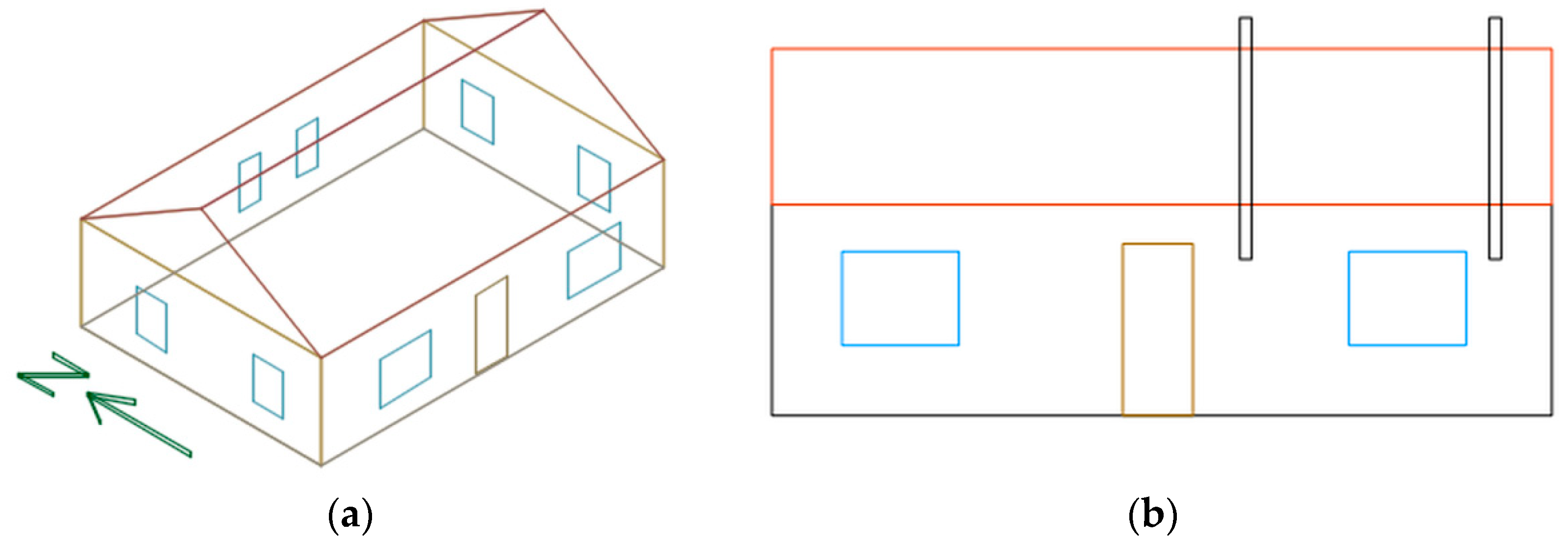
The building is placed on a rectangular plan of 10 m × 7 m and is inhabited by four persons. Longer walls (front and back) are oriented in the east-west axis. It has a usable area of 58.6 m2 and the heated volume of 220.0 m3. The external bearing walls are made in typical technology from hollow clay blocks and are insulated with 10 cm of Styrofoam. Windows are double glazed, with PVC frames and with mean effective total solar energy transmittance ggl = 0.70 and thermal transmittance U = 1.50 W/m2K. Their area on external N-, S-, E- and W-oriented walls is 1.92 m2, 3.60 m2, 1.92 m2 and 1.92 m2, respectively. Exterior doors have a steel skin with 5 cm of polyurethane foam internal insulation. The gable roof (inclined at 30°) is insulated with 15 cm layer of mineral wool. The ground floor is placed on sand and concrete and then 10 cm of insulation from Styrofoam. Solar absorptance of the roof and wall surfaces was: α = 0.8 and α = 0.5, respectively. It was also assumed that the building is provided with the gravity ventilation typical in Poland (Figure 4). Two square ventilation channels with dimensions 14 cm × 14 cm supplied ventilation air to the kitchen and bathroom (Figure 4b). Height h = 2 m.
To calculate the values of elements of the resistance-capacitance circuit from Figure 1 the physical properties of the materials obtained from manufacturers were used. The design heat transmission coefficients were determined following PN-EN ISO 6946. Thermal capacities of the building’s partitions were calculated using the detailed method from PN-EN ISO 13786 for a calculation period of 24 h. The final results are given in Table 1. Heat transfer by ventilation was computed using the procedure given in Section 2.3 assuming volumetric heat capacity of air of 1200 J/(m3K) recommended in EN ISO 13790. The model was then simulated using a spreadsheet.

3. Results and Discussion

3.1. Simulation Cases

For comparative purposes, two simulations were performed. In the first case, it was assumed that no cooling system is in the building. The model of buoyancy-induced stack ventilation, described in Section 2.1, was used. In the second case, the cooling system was added. The last one was a detailed simulation in EnergyPlus tool with no cooling, as in the first case.

3.2. Case 1

In the first case, annual energy for heating amounted to 5493 kWh. It varied from 6 kWh in June to 1045 kWh in January. Hourly heating power varied (Figure 5) from 0 to 3.02 kW on 8 January at 6:00.
Ventilation heat flux (Figure 6) was from −921.0 W on 8 January at 5:00 to 21.4 W on 6 September at 12:00. It means that, except for short periods, the heat was extracted from the interior of the building by ventilation air during the year. It has a negative impact on thermal balance of the building during the heating season, increasing heating demand. In hot periods this effect means that the excess heat is removed, thus enhancing the building’s cooling, especially in case of large solar gains.
The hourly ventilation airflow rate was from −26.8 m3/h on 26 August at 6:00 to 87.2 m3/h on 8 January at 5:00 (Figure 7), with 55.0 m3/h on average. Monthly values were from 42.8 m3/h in September to 67.8 m3/h in January and February.
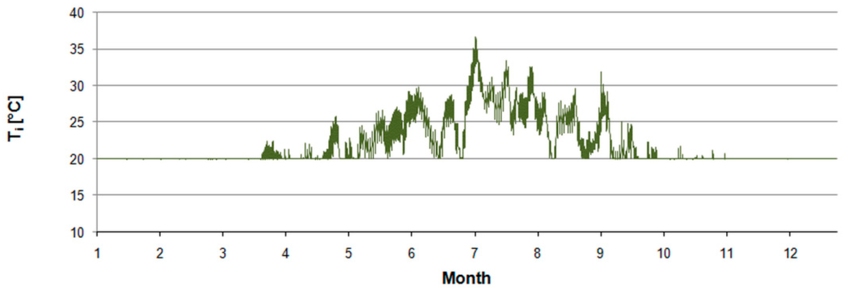
The negative value of ventilation airflow means that air is flowing from the building’s interior to the outdoor environment. The opposite situation may take place during hot summer months, which can be clearly stated when analysing indoor air temperature (Figure 8). Hence, either passive or active cooling is required.

3.3. Case 2

In this case, an additional cooling system was assumed. Annual energy for heating and cooling amounted to 5496 kWh and 143 kWh, respectively. It varied from 7 kWh in June to 1045 kWh in January and from 2 kWh in May to 84 kWh in July. Hourly peak heating and cooling power (Figure 9) amounted to 3.03 kW on 8 January at 6:00 and 0.9 kW on 6 July at 14:00.
Ventilation heat flux was from −921.0 W on 8 January at 5:00 to 78.4 W on 5 July at 13:00. The hourly ventilation airflow rate was from −38.0 m3/h on 26 August at 6:00 to 87.2 m3/h on 8 January at 5:00 (Figure 10), with 53.2 m3/h on average. Monthly values were from 32.4 m3/h in July to 67.8 m3/h in January and February.
Although the extreme values are the same as in the previous case, the waveform shape during the hot period when cooling was active has changed. It was directly connected with a higher indoor-outdoor temperature difference in relation to the previous case.
Assuming the annual average value of the ventilation airflow rate of 53.2 m3/h annual energy for heating and cooling of 6326 kWh and 374 kWh was obtained, respectively. It varied from 8 kWh in June to 1183 kWh in December and from 5 kWh in May to 221 kWh in July.
In this consideration, the assumed discharge coefficient of 0.6 was assumed. However, in [85] from measurements, the value of 0.83 was obtained. This parameter is the most troublesome for estimation. Hence, an uncertainty connected with its proper calculations affects the final results.

3.4. Simulation in EnergyPlus

As aforementioned, simulations in EnergyPlus reflected assumptions set in the first case. Analysis of the air infiltration rate was given in this section to give a better view of the possibilities of the analysed model.
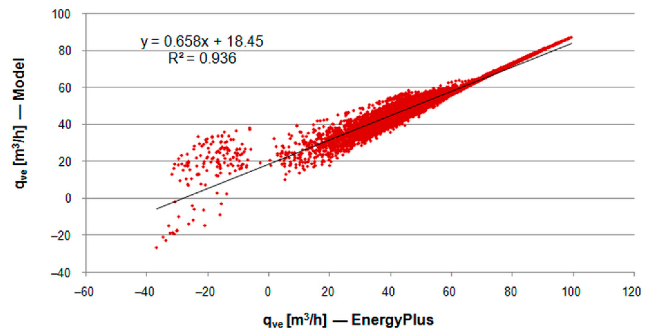
The annual average value of the ventilation airflow rate was 56.9 m3/h when not considering flow direction and 55.5 m3/h if summing both positive and negative values. However, regardless of the direction of flow, contaminated indoor air is replaced by fresh outdoor air. Hence, for design purposes, the indoor-outdoor temperature difference in Equation (1) is computed as the absolute value.
In this study, there were separated situations with opposite flow directions (Figure 11). Calculated coefficient of determination R2 = 0.936 indicated a very strong correlation. Its value means that 96.7% of variations in the reference ventilation airflow from EnergyPlus can be explained by the proposed model.
The average deviation between the value from the analysed model and the reference value from EnergyPlus measured by MAE = 5.72 m3/h. The average squared difference between the reference and predicted values given by MSE = 61.75 m6/h2. Finally, the average distance between the predicted and reference values given by RMSE = 7.86 m3/h.
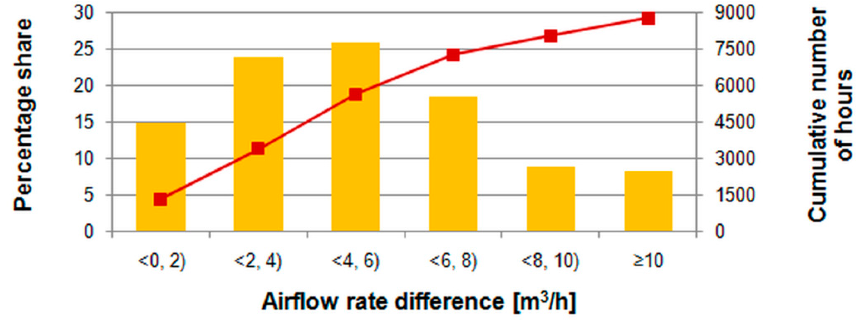
As MAE and RMSE, when compared to the annual average ventilation airflow, are quite similar, it can be deduced that there are no significant large errors in the predictions from the proposed model. The histogram of hourly differences between predictions from the 5R1C model and detailed simulation (Figure 12) proves this outcome.
Differences below 2 m3/h were noticed during 1297 h (14.8% of the year). Values lower than 8 m3/h were observed within 7268 h (83%) which show the good quality of the model.

4. Conclusions

In this study, the thermal network model of a building zone from the EN ISO 13790 standard was linked with the mathematical model of buoyancy-driven natural ventilation to calculate the hourly heating and cooling energy demand of a residential building.
To couple airflow and thermal models, the so-called ping-pong coupling algorithm was applied. This way, calculations were performed by avoiding circular references and using the generic method provided by EN ISO 13790 applied in a spreadsheet.
The chosen thermal model of a building showed its applicability in combination with the proposed algorithm. The method is simple and does not require the use of sophisticated building simulation tools. Presented statistical analysis proved its quality sufficient for simple calculations in terms of simple energy analyses. It also enables predictions of the airflow direction and ventilation heat flux which is the first step to assessing the necessity to apply, for example, night cooling or other ventilation strategies to minimise overheating risk or preheating to reduce ventilation loss.
It should be emphasized that the simplifications associated with this type of description of natural ventilation will certainly deviate from the results obtained from CFD tools or measurements. The simplifications associated with this type of description of natural ventilation will certainly deviate from the results obtained from CFD tools or measurements. Nevertheless, simulation in an hourly step with the choice of Cd according to the results of accurate studies allows the buoyancy phenomenon to be taken into account more accurately than, for example, an averaged ventilation flow over the year, independent of indoor and outdoor conditions.
In the next step, other coupling algorithms could be studied and comparisons with the more detailed tools can be used for comparison. It also seems reasonable to include the impact of wind velocity and direction into the calculation procedure to more accurately include the impact of environmental conditions on the performance of natural ventilation.

Funding

This research received no external funding.

Institutional Review Board Statement

Not applicable.

Informed Consent Statement

Not applicable.

Data Availability Statement

Not applicable.

Conflicts of Interest

The author declares no conflict of interest.

Abbreviations

Aconstant term coefficient, —
Abottombottom ventilation opening area, m2
Aeffeffective ventilation opening area, m2
Aftotal conditioned (heated and/or cooled) floor area, m2
ALeffective air leakage area that corresponds to a 4 Pa pressure differential, cm2
Ameffective thermal mass area, m2
Aopeningopening area, m2
Atarea of all surfaces facing the a building zone, m2
Atoptop ventilation opening area, m2
Btemperature term coefficient, K−1
Cvelocity term coefficient, s/m
Cdthe discharge coefficient, —
Cminternal thermal capacity of the considered building (or zone), J/K
Cscoefficient for stack-induced infiltration in (L/s)2/(cm4·K)
C’scoefficient for stack-induced infiltration, (Pa/K)n
Cwcoefficient for wind-induced infiltration, (L/s)2/(cm4·(m/s)2)
C’wcoefficient for wind-induced infiltration, (Pa·s2/m2)n
Dvelocity squared term coefficient, (s/m)2
Fschedulevalue from a user-defined schedule, —
Htr,emexternal part of the Htr,op thermal transmission coefficient, W/K
Htr,iscoupling conductance, W/K
Htr,msinternal part of the Htr,op thermal transmission coefficient, W/K
Htr,mscoupling conductance between nodes m and s, W/K;
Htr,opthermal transmission coefficient for thermally heavy envelope elements, W/K
Hvethermal transmission coefficient by ventilation air, W/K
Htr,wthermal transmission coefficient for thermally light envelope elements, W/K
Teexternal (outdoor) air temperature, K
Tiinternal (indoor) air temperature, K
Tmthermal mass node temperature, K
Tscentral node temperature, K
Tsupsupply air temperature, K
Cflow coefficient, m3/(s·(Pa)n)
caspecific heat of air at constant pressure, J/(kg∙K)
ggravitational acceleration, m/s2
hheight between the bottom and top openings, m
hmsheat transfer coefficient between nodes m and s, with fixed value hms = 9.1W/m2K;
hisheat transfer coefficient between the air node, Ti, and the surface node, Ts, with a fixed value of his = 3.45 W/m2K;
npressure exponent, —
qdesigndesign ventilation airflow rate, m3/s
sshelter factor, —
wlocal wind speed, m/s
ρaair density, kg/m3
φintheat flow rate due to internal heat sources, W
φsolheat flow rate due to solar heat sources, W
φiaheat flow rate to the internal air node, W
φstheat flow rate to the central node, W
φmheat flow rate to the mass node, W
φveheat flow rate by ventilation, W
φHCheating or cooling power supplied to or extracted from the indoor air node, W
ΔHNPLHeight from the midpoint of lower opening to the neutral pressure level, m

References

  1. Papadopoulos, A.M.; Papageorgiou, K.P.; Karatzas, K. Evaluation of an attached sunspace without sun protection: How feasible is this approach in mediterranean summer conditions? Int. J. Sol. Energy 2002, 22, 93–104. [Google Scholar] [CrossRef]
  2. Aristov, Y.I. Current progress in adsorption technologies for low-energy buildings. Future Cities Environ. 2015, 1, 10. [Google Scholar] [CrossRef]
  3. Ivanović-Šekularac, J.; Čikić-Tovarović, J.; Šekularac, N. Application of wood as an element of façade cladding in construction and reconstruction of architectural objects to improve their energy efficiency. Energy Build. 2016, 115, 85–93. [Google Scholar] [CrossRef]
  4. Witkowska, A.; Krawczyk, D.A.; Rodero, A. Investment costs of heating in Poland and Spain—A case study. Proceedings 2019, 16, 40. [Google Scholar] [CrossRef] [Green Version]
  5. D’Agostino, D.; Zangheri, P.; Castellazzi, L. Towards nearly zero energy buildings in Europe: A focus on retrofit in non-residential buildings. Energies 2017, 10, 117. [Google Scholar] [CrossRef]
  6. Cieśliński, K.; Tabor, S.; Szul, T. Evaluation of energy efficiency in thermally improved residential buildings, with a weather controlled central heating system. A case study in Poland. Appl. Sci. 2020, 10, 8430. [Google Scholar] [CrossRef]
  7. Đukanović, L.; Ignjatović, D.; Ćuković Ignjatović, N.; Rajčić, A.; Lukić, N.; Zeković, B. Energy refurbishment of Serbian school building stock—A typology tool methodology development. Sustainability 2022, 14, 4074. [Google Scholar] [CrossRef]
  8. Pantović, V.; Petrović-Bećirović, S.B. Rising public awareness of energy efficiency of buildings enhanced by “Smart” controls of the in-door environment. Therm. Sci. 2016, 20, 1307–1319. [Google Scholar] [CrossRef]
  9. Harmathy, N.; Urbancl, D.; Goricanec, D.; Magyar, Z. Energy efficiency and economic analysis of retrofit measures for single-family residential buildings. Therm. Sci. 2019, 23, 1307–1319. [Google Scholar] [CrossRef]
  10. Allard, I.; Nair, G.; Olofsson, T. Energy performance criteria for residential buildings: A comparison of Finnish, Norwegian, Swedish, and Russian building codes. Energy Build. 2021, 250, 111276. [Google Scholar] [CrossRef]
  11. Filippov, S.P.; Dil’man, M.D.; Ionov, M.S. The optimum levels of the thermal protection of residential buildings under climatic conditions of Russia. Therm. Eng. 2013, 60, 841–851. [Google Scholar] [CrossRef]
  12. Verstina, N.; Solopova, N.; Taskaeva, N.; Meshcheryakova, T.; Shchepkina, N. A new approach to assessing the energy efficiency of industrial facilities. Buildings 2022, 12, 191. [Google Scholar] [CrossRef]
  13. Giama, E. Review on ventilation systems for building applications in terms of energy efficiency and environmental impact assessment. Energies 2022, 15, 98. [Google Scholar] [CrossRef]
  14. Aflaki, A.; Esfandiari, M.; Mohammadi, S. A Review of numerical simulation as a precedence method for prediction and evaluation of building ventilation performance. Sustainability 2021, 13, 12721. [Google Scholar] [CrossRef]
  15. Statistics Poland. National Census of Population and Housing 2011. Available online: https://stat.gov.pl/en/national-census/national-census-of-population-and-housing-2011/ (accessed on 1 April 2022).
  16. Inhabited Buildings [in Polish] National Census of Population and Housing; Statistics Poland: Warsaw, Poland, 2013. Available online: https://stat.gov.pl/cps/rde/xbcr/gus/L_zamieszk_budynki_nsp_2011.pdf (accessed on 1 April 2022).
  17. Development of Methodology and Realisation of a Survey of a Scale of Thermo-Modernization Activity in Multi-Dwelling Residential Buildings in order to Improve Their Energy Consumption and Estimation of Needs and Plans in This Area; Final Report; Statistics Poland: Warsaw, Poland, 2018. Available online: https://stat.gov.pl/statystyki-eksperymentalne/srodowisko-efektywnosc-energetyczna/opracowanie-metodologii-i-przeprowadzenie-badania-skali-dzialan-termomodernizacyjnych-budynkow-mieszkalnych-wielomieszkaniowych-w-celu-poprawy-ich-energochlonnosci-oraz-ocena-potrzeb-i-planowanych-,1,1.html (accessed on 1 April 2022). (In Polish)
  18. Wang, S.; Yan, C.; Xiao, F. Quantitative energy performance assessment methods for existing buildings. Energy Build. 2012, 55, 873–888. [Google Scholar] [CrossRef]
  19. Koulamas, C.; Kalogeras, A.P.; Pacheco-Torres, R.; Casillas, J.; Ferrarini, L. Suitability analysis of modeling and assessment approaches in energy efficiency in buildings. Energy Build. 2018, 158, 1662–1682. [Google Scholar] [CrossRef]
  20. Tüysüz, F.; Sözer, H. Calibrating the building energy model with the short term monitored data: A case study of a large-scale residential building. Energy Build. 2020, 224, 110207. [Google Scholar] [CrossRef]
  21. Oraiopoulos, A.; Howard, B. On the accuracy of urban building energy modelling. Renew. Sustain. Energy Rev. 2022, 158, 111976. [Google Scholar] [CrossRef]
  22. Kalogirou, S.A.; Papamarcou, C. Modeling of a thermosyphon solar water heating system and simple model validation. Renew. Energy 2000, 21, 471–493. [Google Scholar] [CrossRef]
  23. Steen Englund, J.; Cehlin, M.; Akander, J.; Moshfegh, B. Measured and simulated energy use in a secondary school building in Sweden—A case study of validation, airing, and occupancy behaviour. Energies 2020, 13, 2325. [Google Scholar] [CrossRef]
  24. Malkawi, A.; Yan, B.; Chen, Y.; Tong, Z. Predicting thermal and energy performance of mixed-mode ventilation using an integrated simulation approach. Build. Simul. 2016, 9, 335–346. [Google Scholar] [CrossRef]
  25. Yoon, N.; Piette, M.A.; Han, J.M.; Wu, W.; Malkawi, A. Optimization of window positions for wind-driven natural ventilation performance. Energies 2020, 13, 2464. [Google Scholar] [CrossRef]
  26. Rodrigues Marques Sakiyama, N.; Frick, J.; Bejat, T.; Garrecht, H. Using CFD to evaluate natural ventilation through a 3D parametric modeling approach. Energies 2021, 14, 2197. [Google Scholar] [CrossRef]
  27. Wang, Y.; Yu, Y.; Ye, T.; Bo, Q. Ventilation characteristics and performance evaluation of different window-opening forms in a typical office room. Appl. Sci. 2021, 11, 8966. [Google Scholar] [CrossRef]
  28. Prueksakorn, K.; Piao, C.-X.; Ha, H.; Kim, T. Computational and experimental investigation for an optimal design of industrial windows to allow natural ventilation during wind-driven rain. Sustainability 2015, 7, 10499–10520. [Google Scholar] [CrossRef] [Green Version]
  29. Hensen, J. A comparison of coupled and de-coupled solutions for temperature and air flow in a building. ASHRAE Trans. 1999, 105, 962–969. [Google Scholar]
  30. Jreijiry, D.; Husaunndee, A.; Inard, C.; Villenave, J.G. Control of ventilation in buildings using SIMBAD building and HVAC toolbox. In Proceedings of the Building Simulation 2003, Eighth International IBPSA Conference, Eindhoven, The Netherlands, 11–14 August 2003; pp. 591–598. Available online: http://www.ibpsa.org/proceedings/bs2003/bs03_0591_598.pdf (accessed on 6 April 2022).
  31. Megri, A.C. Building load and energy simulation programs and the design process. Int. J. Vent. 2007, 6, 177–192. [Google Scholar] [CrossRef]
  32. Trčka, M.; Hensen, J.L.M.; Wetter, M. Co-simulation for performance prediction of integrated building and HVAC systems—An analysis of solution characteristics using a two-body system. Simul. Model. Pract. Theory 2010, 18, 957–970. [Google Scholar] [CrossRef] [Green Version]
  33. Shen, X.; Guo, Q.; Lin, G.; Zeng, Y.; Hu, Z. Study on loose-coupling methods for aircraft thermal anti-icing system. Energies 2020, 13, 1463. [Google Scholar] [CrossRef] [Green Version]
  34. Baglivo, C.; D’Agostino, D.; Congedo, P.M. Design of a ventilation system coupled with a horizontal air-ground heat exchanger (HAGHE) for a residential building in a warm climate. Energies 2018, 11, 2122. [Google Scholar] [CrossRef] [Green Version]
  35. Vasaturo, R.; van Hooff, T.; Kalkman, I.; Blocken, B.; van Wesemael, P. Impact of passive climate adaptation measures and building orientation on the energy demand of a detached lightweight semi-portable building. Build. Simul. 2018, 11, 1163–1177. [Google Scholar] [CrossRef] [Green Version]
  36. Grygierek, K.; Ferdyn-Grygierek, J.; Gumińska, A.; Baran, Ł.; Barwa, M.; Czerw, K.; Gowik, P.; Makselan, K.; Potyka, K.; Psikuta, A. Energy and environmental analysis of single-family houses located in Poland. Energies 2020, 13, 2740. [Google Scholar] [CrossRef]
  37. Ignjatović, M.; Blagojević, B.; Stojanović, B.; Stojiljković, M. Influence of glazing types and ventilation principles in double skin façades on delivered heating and cooling energy during heating season in an office building. Therm. Sci. 2012, 16, 461–469. [Google Scholar] [CrossRef]
  38. Luo, C.; Gong, Y.; Ma, W.; Zhao, J. Building energy efficiency in Guangdong province. China. Therm. Sci. 2019, 23, 3251–3262. [Google Scholar] [CrossRef]
  39. Bagheri Moghaddam, F.; Fort Mir, J.M.; Besné Yanguas, A.; Navarro Delgado, I.; Redondo Dominguez, E. Building orientation in green facade performance and its positive effects on urban landscape case study: An urban block in Barcelona. Sustainability 2020, 12, 9273. [Google Scholar] [CrossRef]
  40. Harish, V.S.K.V.; Kumar, A.; Alam, T.; Blecich, P. Assessment of state-space building energy system models in terms of stability and controllability. Sustainability 2021, 13, 11938. [Google Scholar] [CrossRef]
  41. Wang, Q.; Holmberg, S. A methodology to assess energy-demand savings and cost effectiveness of retrofitting in existing Swedish residential buildings. Sustain. Cities Soc. 2015, 14, 254–266. [Google Scholar] [CrossRef]
  42. Schito, E.; Testi, D.; Conti, P.; Grassi, W. Validation of seas, a quasi-steady-state tool for building energy audits. Energy Procedia 2015, 78, 3192–3197. [Google Scholar] [CrossRef]
  43. Ćuković Ignjatović, N.; Ignjatović, D.; Stanković, B. Possibilities for energy rehabilitation of typical single family house in Belgrade—Case study. Energy Build. 2016, 115, 154–162. [Google Scholar] [CrossRef]
  44. EN ISO 13790; Energy Performance of Buildings—Calculation of Energy Use for Space Heating and Cooling. International Organization for Standardization: Geneva, Switzerland, 2009.
  45. EN ISO 52016-1; Energy performance of Buildings—Energy Needs for Heating and Cooling, Internal Temperatures and Sensible and Latent Heat Loads—Part 1: Calculation Procedures. International Organization for Standardization: Geneva, Switzerland, 2017.
  46. Mora-Pérez, M.; Guillen-Guillamón, I.; López-Patiño, G.; López-Jiménez, P.A. Natural Ventilation Building Design Approach in Mediterranean Regions—A Case Study at the Valencian Coastal Regional Scale (Spain). Sustainability 2016, 8, 855. [Google Scholar] [CrossRef] [Green Version]
  47. Kwiatkowski, J.; Rucińska, J. Estimation of energy efficiency class limits for multi-family residential buildings in Poland. Energies 2020, 13, 6234. [Google Scholar] [CrossRef]
  48. Pierangioli, L.; Cellai, G.; Ferrise, R.; Trombi, G.; Bindi, M. Effectiveness of passive measures against climate change: Case studies in Central Italy. Build Simul. 2017, 10, 459–479. [Google Scholar] [CrossRef]
  49. Pernigotto, G.; Prada, A.; Costola, D.; Gasparella, A.; Hensen, J.L.M. Multi-year and reference year weather data for building energy labelling in north Italy climates. Energy Build. 2014, 72, 62–72. [Google Scholar] [CrossRef] [Green Version]
  50. Tronchin, L.; Manfren, M.; Tagliabue, L.C. Optimization of building energy performance by means of multi-scale analysis—Lessons learned from case studies. Sustain. Cities Soc. 2016, 27, 296–306. [Google Scholar] [CrossRef]
  51. Manic, D.J.; Komatina, M.S.; Vucicevic, B.S.; Jovanovic, M.P. Energy performance of single family houses in Serbia–analysis of calculation procedures. Therm. Sci. 2019, 23, 1695–1705. [Google Scholar] [CrossRef] [Green Version]
  52. Carlsson, M.; Touchie, M.; Richman, R. Investigating the potential impact of a compartmentalization and ventilation system retrofit strategy on energy use in high-rise residential buildings. Energy Build. 2019, 199, 20–28. [Google Scholar] [CrossRef]
  53. Deshko, V.; Bilous, I.; Sukhodub, I.; Yatsenko, O. Evaluation of energy use for heating in residential building under the influence of air exchange modes. J. Build. Eng. 2021, 42, 103020. [Google Scholar] [CrossRef]
  54. Panagiotidu, M.; Aye, L.; Rismanchi, B. Optimisation of multi-residential building retrofit, cost-optimal and net-zero emission targets. Energy Build. 2021, 252, 111385. [Google Scholar] [CrossRef]
  55. Albatayneh, A.; Jaradat, M.; AlKhatib, M.B.; Abdallah, R.; Juaidi, A.; Manzano-Agugliaro, F. The significance of the adaptive thermal comfort practice over the structure retrofits to sustain indoor thermal comfort. Energies 2021, 14, 2946. [Google Scholar] [CrossRef]
  56. Monna, S.; Juaidi, A.; Abdallah, R.; Albatayneh, A.; Dutournie, P.; Jeguirim, M. Towards sustainable energy retrofitting, a simulation for potential energy use reduction in residential buildings in Palestine. Energies 2021, 14, 3876. [Google Scholar] [CrossRef]
  57. Ecim-Djuric, O.; Topisirovic, G. Energy efficiency optimization of combined ventilation systems in livestock buildings. Energy Build. 2010, 42, 1165–1171. [Google Scholar] [CrossRef]
  58. Bogdanović Protić, I.; Mitković, M. Town planning parameters in the function of building energy efficiency. Facta Univ. Ser. Archit. Civ. Eng. 2015, 13, 1–9. [Google Scholar] [CrossRef] [Green Version]
  59. Bojić, M.; Kostić, S. Application of COMIS software for ventilation study in a typical building in Serbia. Build. Environ. 2006, 41, 12–20. [Google Scholar] [CrossRef]
  60. Firla̧g, S.; Zawada, B. Impacts of airflows, internal heat and moisture gains on accuracy of modeling energy consumption and indoor parameters in passive building. Energy Build. 2013, 64, 372–383. [Google Scholar] [CrossRef]
  61. Arendt, K.; Krzaczek, M.; Tejchman, J. Influence of input data on airflow network accuracy in residential buildings with natural wind- and stack-driven ventilation. Build. Simul. 2017, 10, 229–238. [Google Scholar] [CrossRef]
  62. Ryzhov, A.; Ouerdane, H.; Gryazina, E.; Bischi, A.; Turitsyn, K. Model predictive control of indoor microclimate: Existing building stock comfort improvement. Energy Convers. Manag. 2019, 179, 219–228. [Google Scholar] [CrossRef] [Green Version]
  63. Jędrzejuk, H.; Rucińska, J. Verifying a need of artificial cooling—A simplified method dedicated to single-family houses in Poland. Energy Procedia 2015, 78, 1093–1098. [Google Scholar] [CrossRef] [Green Version]
  64. Oliveira Panão, M.J.N.; Santos, C.A.P.; Mateus, N.M.; Carrilho da Graça, G. Validation of a lumped RC model for thermal simulation of a double skin natural and mechanical ventilated test cell. Energy Build. 2016, 121, 92–103. [Google Scholar] [CrossRef]
  65. Jayathissa, P.; Luzzatto, M.; Schmidli, J.; Hofer, J.; Nagy, Z.; Schlueter, A. Optimising building net energy demand with dynamic BIPV shading. Appl. Energy 2017, 202, 726–735. [Google Scholar] [CrossRef]
  66. Shen, P.; Braham, W.; Yi., Y. Development of a lightweight building simulation tool using simplified zone thermal coupling for fast parametric study. Applied Energy 2018, 223, 188–214. [Google Scholar] [CrossRef]
  67. Lauster, M.; Teichmann, J.; Fuchs, M.; Streblow, R.; Mueller, D. Low order thermal network models for dynamic simulations of buildings on city district scale. Build. Environ. 2014, 73, 223–231. [Google Scholar] [CrossRef]
  68. Horvat, I.; Dović, D. Dynamic modeling approach for determining buildings technical system energy performance. Energy Convers. Manag. 2016, 125, 154–165. [Google Scholar] [CrossRef]
  69. Elci, M.; Delgado, B.M.; Henning, H.M.; Henze, G.P.; Herkel, S. Aggregation of residential buildings for thermal building simulations on an urban district scale. Sustain. Cities Soc. 2018, 39, 537–547. [Google Scholar] [CrossRef]
  70. Tagliabue, L.C.; Buzzetti, M.; Marenzi, G. Energy performance of greenhouse for energy saving in buildings. Energy Procedia 2012, 30, 1233–1242. [Google Scholar] [CrossRef] [Green Version]
  71. Fabrizio, E.; Ghiggini, A.; Bariani, M. Energy performance and indoor environmental control of animal houses: A modelling tool. Energy Procedia 2015, 82, 439–444. [Google Scholar] [CrossRef] [Green Version]
  72. Fischer, D.; Wolf, T.; Scherer, J.; Wille-Haussmann, B. A stochastic bottom-up model for space heating and domestic hot water load profiles for German households. Energy Build. 2016, 124, 120–128. [Google Scholar] [CrossRef]
  73. Costantino, A.; Fabrizio, E.; Ghiggini, A.; Bariani., M. Climate control in broiler houses: A thermal model for the calculation of the energy use and indoor environmental conditions. Energy Build. 2018, 169, 110–126. [Google Scholar] [CrossRef]
  74. Hedegaard, R.E.; Kristensen, M.H.; Pedersen, T.H.; Brun, A.; Petersen, S. Bottom-up modelling methodology for urban-scale analysis of residential space heating demand response. Appl. Energy 2019, 242, 181–204. [Google Scholar] [CrossRef]
  75. Costantino, A.; Comba, L.; Sicardi, G.; Bariani, M.; Fabrizio, E. Energy performance and climate control in mechanically ventilated greenhouses: A dynamic modelling-based assessment and investigation. Appl. Energy 2021, 288, 116583. [Google Scholar] [CrossRef]
  76. Buonomano, A.; Forzano, C.; Kalogirou, S.A.; Palombo, A. Building-façade integrated solar thermal collectors: Energy-economic performance and indoor comfort simulation model of a water based prototype for heating, cooling, and DHW production. Renew. Energy 2019, 137, 20–36. [Google Scholar] [CrossRef]
  77. Narowski, P.; Mijakowski, M.; Sowa, J. Integrated calculations of thermal behaviour of both buildings and ventilation and air conditioning systems. In Proceedings of the Eleventh International IBPSA Conference, Glasgow, Scotland, 27–30 July 2009; Available online: http://www.ibpsa.org/proceedings/bs2009/bs09_0875_882.pdf (accessed on 6 April 2022).
  78. Michalak, P. A thermal network model for the dynamic simulation of the energy performance of buildings with the time varying ventilation flow. Energy Build. 2019, 202, 109337. [Google Scholar] [CrossRef]
  79. Soleimani, Z.; Calautit, J.K.; Hughes, B.R. Computational Analysis of Natural Ventilation Flows in Geodesic Dome Building in Hot Climates. Computation 2016, 4, 31. [Google Scholar] [CrossRef] [Green Version]
  80. Stamatopoulos, P.; Drosatos, P.; Nikolopoulos, N.; Rakopoulos, D. Determination of a Methodology to derive correlations between window opening mass flow rate and wind conditions based on CFD results. Energies 2019, 12, 1600. [Google Scholar] [CrossRef] [Green Version]
  81. Chen, C.-M.; Lin, Y.-P.; Chung, S.-C.; Lai, C.-M. Effects of the design parameters of ridge vents on induced buoyancy-driven ventilation. Buildings 2022, 12, 112. [Google Scholar] [CrossRef]
  82. De Vita, M.; Duronio, F.; De Vita, A.; De Berardinis, P. Adaptive retrofit for adaptive reuse: Converting an industrial chimney into a ventilation duct to improve internal comfort in a historic environment. Sustainability 2022, 14, 3360. [Google Scholar] [CrossRef]
  83. Sowa, J. Trends in the Polish Building Ventilation Market and Drivers for Changes. AIVC VIP 24. 2008. Available online: https://www.aivc.org/sites/default/files/medias/pdf/Free_VIPs/VIP24_Poland.pdf (accessed on 6 April 2022).
  84. Krzaczek, M.; Florczuk, J.; Tejchman, J. Field investigations of stack ventilation in a residential building with multiple chimneys and tilted window in cold climate. Energy Build. 2015, 103, 48–61. [Google Scholar] [CrossRef]
  85. Antczak-Jarząbska, R.; Niedostatkiewicz, M. Natural ventilation performance of family building in cold climate during windless time. Diagnostyka 2018, 19, 21–28. [Google Scholar] [CrossRef]
  86. Zheng, X.; Shi, Z.; Xuan, Z.; Qian, H. Natural Ventilation. In Handbook of Energy Systems in Green Buildings; Wang, R., Zhai, X., Eds.; Springer: Berlin/Heidelberg, Germany, 2018. [Google Scholar] [CrossRef]
  87. Medved, S.; Domjan, S.; Arkar, C. Ventilation of nZEB. In Sustainable Technologies for Nearly Zero Energy Buildings; Springer Tracts in Civil Engineering; Springer: Cham, Switzerland, 2019. [Google Scholar] [CrossRef]
  88. Michalak, P. Thermal-electrical analogy in dynamic simulations of buildings: Comparison of four numerical solution methods. J. Mech. Energy Eng. 2020, 4, 179–188. [Google Scholar] [CrossRef]
  89. U.S. Department of Energy. Input Output Reference. EnergyPlus™ Version 9.6.0 Documentation; 23 September 2021. Available online: https://energyplus.net/assets/nrel_custom/pdfs/pdfs_v9.6.0/InputOutputReference.pdf (accessed on 10 May 2022).
  90. ASHRAE Handbook Fundamentals, SI ed.; American Society of Heating, Refrigerating and Air Conditioning Engineers: Atlanta, GA, USA, 2001.
  91. Adeala, A.A.; Huan, Z.; Enweremadu, C.C. Evaluation of global solar radiation using multiple weather parameters as predictors for South Africa Provinces. Therm. Sci. 2015, 19, 495–509. [Google Scholar] [CrossRef]
  92. Pham, H. A new criterion for model selection. Mathematics 2019, 7, 1215. [Google Scholar] [CrossRef] [Green Version]
  93. Kadad, I.M.; Ramadan, A.A.; Kandil, K.M.; Ghoneim, A.A. Relationship between ultraviolet-b radiation and broadband solar radiation under all sky conditions in kuwait hot climate. Energies 2022, 15, 3130. [Google Scholar] [CrossRef]
  94. Salah, S.; Alsamamra, H.R.; Shoqeir, J.H. Exploring wind speed for energy considerations in eastern Jerusalem-Palestine using machine-learning algorithms. Energies 2022, 15, 2602. [Google Scholar] [CrossRef]
  95. Data for Energy Calculations of Buildings. Typical Meteorological Years and Statistical Climatic Data for Energy Calculations of Buildings. Available online: https://www.gov.pl/web/archiwum-inwestycje-rozwoj/dane-do-obliczen-energetycznych-budynkow (accessed on 9 March 2022).
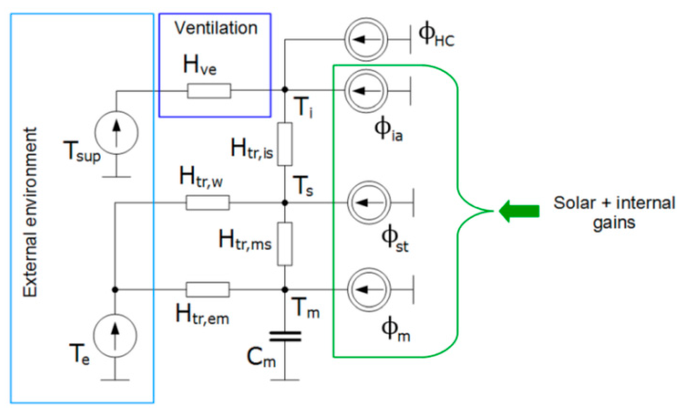
Figure 1. The 5R1C thermal network model of a building zone from EN ISO 13790.
Energies 15 04175 g001
Figure 2. Ping-pong coupling algorithm in the calculation of the 5R1C model with stack ventilation.
Energies 15 04175 g002
Figure 3. TMY for Nowy Sącz: (a) Outdoor air temperature; (b) Wind velocity.
Energies 15 04175 g003
Figure 4. The studied building: (a) Isometric view; (b) Location of ventilation channels (front view).
Energies 15 04175 g004
Figure 5. Hourly heating power in case 1.
Energies 15 04175 g005
Figure 6. Hourly ventilation heat flux in case 1.
Energies 15 04175 g006
Figure 7. Hourly (orange) and monthly (black) ventilation airflow rate in case 1.
Energies 15 04175 g007
Figure 8. Hourly indoor air temperature in the building.
Energies 15 04175 g008
Figure 9. Hourly heating and cooling power in case 2.
Energies 15 04175 g009
Figure 10. Hourly (orange) and monthly (black) ventilation airflow rate in case 2.
Energies 15 04175 g010
Figure 11. Hourly ventilation airflow from EnergyPlus and the presented model.
Energies 15 04175 g011
Figure 12. Histogram of hourly differences between ventilation airflow from EnergyPlus and the presented model.
Energies 15 04175 g012
Table 1. Thermal network model elements of the building.
ElementValueUnit
Htr,w6.24W/K
Htr,is804.06W/K
Htr,ms1151.15W/K
Htr,em70.02W/K
Cm15.57MJ/K
Publisher’s Note: MDPI stays neutral with regard to jurisdictional claims in published maps and institutional affiliations.