Article

Design and Analysis of Sliding-Mode Artificial Neural Network Control Strategy for Hybrid PV-Battery-Supercapacitor System

1
Control & Energy Management Laboratory, Sfax Engineering School, University of Sfax, Sfax 3038, Tunisia
2
Department of Electrical Engineering, College of Engineering, University of Ha’il, Ha’il 2240, Saudi Arabia
*
Author to whom correspondence should be addressed.
Energies 2022, 15(11), 4099; https://doi.org/10.3390/en15114099
Submission received: 10 May 2022 / Revised: 28 May 2022 / Accepted: 1 June 2022 / Published: 2 June 2022
(This article belongs to the Section F: Electrical Engineering)

Abstract

:
Nowadays, the growing integration of renewable energy sources poses several challenges to electrical energy systems. The latter need be controlled by grid rules to ensure their stability and maintain the efficiency of renewable energy consumption. In this context, a novel HESS (hybrid energy storage system) control strategy, combining the PV (photovoltaic) generator with FLC (fuzzy logic control), SC (super-capacitor), and lithium-ion battery modules, is advanced. The proposed energy control rests on monitoring of the low-frequency and high-frequency electrical power components of the mismatch between power demand and generation, while applying the error component of the lithium-ion battery current. On accounting for the climatic condition and load variation considerations, the SC undertakes to momentarily absorb the high-frequency power component, while the low-frequency component is diverted to the lithium-ion battery. To improve the storage system’s performance, lifetime, and avoid load total disconnection during sudden variations, we consider equipping the envisioned energy control design with controllers of SM and ANN types. The MATLAB/Simulink based simulation results turn out to testify well the investigated HESS control scheme’s outstanding performance and efficiency in terms of DC bus voltage rapid regulation, thereby enhancing the battery’s lifetime and ensuring the PV system’s continuous flow.

1. Introduction

The global challenges associated with electrical energy along with the related environmental impacts have enhanced the integration of renewable power sources and the launch of efficient smart micro-grid technologies [1,2]. Additionally, the increasing introduction of renewable biomass has paved the way for boosting the electrical energy sector [3]. Low-voltage micro-grids have drawn the interest of several researchers. A microgrid is an autonomous small-scale power system incorporating several conventional and renewable energy generating sources, energy storage systems (ESSs), and electrical power converters. Micro-grids can be operated autonomously or with the help of a utility grid [4,5,6,7]. The ability to generate and provide electricity to remote communities without the need for high-voltage transmission and distribution systems, highly expensive and inefficient over long distances, is a significant advantage a micro-grid can provide [8,9]. Owing to its limited capacity and recurrent resource intermittency, however, sustaining a resilient, high-quality, and dependent standalone microgrid turns out to be a difficult process [10]. With an intermittent profile, standalone electrical systems rely largely on ESSs. Currently, the battery-reliant storage systems appear to offer a promising potential to reduce the difficulties of demand-generation oscillations in the greatest real RAPSAs [11,12,13].
In this respect, the lead–acid and lithium-ion batteries stand as the most commonly useful energy storing devices, applied in standalone photovoltaic systems [13]. The energy storage designed batteries are characterized with a great energy density and low-power density, resulting in little charge/discharge rates [14]. As for both battery types’ respective performance, the lead–acid battery associated loss rates are much higher, with loss figures ranging between 15 and 20%, whereas the lithium-ion battery related losses are generally inferior, with rates ranging between 2 and 8%. Another disadvantage of lead–acid batteries is that they require a longer charging time than lithium-ion batteries. Inadequate regular charging of lead–acid batteries, mainly during the winter season, can considerably reduce the life span of such batteries. Comparatively, however, the SCs have a high power and low energy density, usually resulting in frequent charge/discharge rates. The relevant literature provides a comparison established between batteries and SCs associated performance [15,16], as depicted in Table 1, below.
Several loads, such as the motor, air-conditioner, and refrigerator loads, require a noticeable current input to start, usually ranging from 7 to 10 times the average operating current. Moreover, the high current amount required by the load can be satisfied for only a very short time (a few moments). To cope with this high power demand, battery sizing, usually upgraded every 3 to 5 years, is usually a costly process. Hence, an ideal ESS, fit for implementation in a standalone renewable system, seems worth applying, enabling one to simultaneously maintain a high energy flow and a remarkable power range capacity, as well as to be able to manage sudden climatic conditions and load profile-related scenarios. Accordingly, our major purpose lies in combining the benefits provided by lithium-ion batteries with SCs’ displayed advantages to come up with a novel ESS architecture whereby both high energy flow and power density features could be simultaneously maintained. Thus, deploying a special battery-SC design, we consider, is likely to provide a greater lifetime enhancement process, wherein the size, stress, and storage costs could be significantly reduced. Noteworthy, also, is that the envisaged framework is conceived in such a way that ensures a smooth input/output power balance (i.e., between production and consumption) could be persistently guaranteed.
It is worth recalling that a wide range of SC/battery power-share control algorithms have so far been published, mainly in [13,14,15,16,17,18,19,20,21,22,23,24,25,26]. Most of these control strategies predominantly involve neural networks, rule-based and model predictive controls, as well as fuzzy logic [17]. Actually, a special computation of the battery lifespan improvement associated with the incorporation of an SC storage device has been provided in [22]. In [13], the SC provided advantages, incorporated into a battery-based storage system regarding a wind-based hybrid RAPSA, have been investigated. Accordingly, an EMA involving a battery and an SC storage system has already been built in order to run both in a predetermined way. Special HESS microgrid-related applications were documented in [14]. Research dealing with decreasing battery stress through implementation of an SC has been conducted in [18]. In [19], it has been proved that the HESS could reduce battery costs while increasing overall system efficiency. In [20], an ANN was used to construct and control an electrical-vehicle-devoted HESS. Moreover, a special rule-based control system fit for adapting and integrating a battery storage system and solar-wind energy sources has been elaborated on [21]. Still, the already-advanced solutions appear to display a number of limitations, relating mainly to the need for vast amounts of data storage capacity and expensive computation processes. A special MPC, fit for implementation with a hybrid electrical power source, is provided in [27,28]. The method’s major disadvantage, however, lies in the complex mathematical processing it requires due to its heavy reliance on the traditional MPC. In [23], several stand-alone HESS based REPS structures, such as active, semi-active, and passive HESS, are displayed for the purpose of assessing their technical and economical features. Similarly, a new topology of passive HESS based on the PWM signal generation method is investigated in [24]. However, the entirety of these suggested energy management strategic methods are not without any drawbacks, such as low robustness against sudden variations of weather conditions and load and the complex mathematical computation procedures they require. Worth citing, also, is the energy control investigation study dealing with a PV–battery–diesel hybrid system conducted in [29]. In the same vein of thought, the viability of a PV–battery–diesel hybrid system’s combined dispatch control strategy is also investigated in [30], by integrating load following and cycle charging processes. A special DC electrical microgrid system with improved energy control strategy that rests on the PV modules, battery, and DC load is treated in [31]. In [32], an adaptive dynamic-based EMS adapted to a series-parallel hybrid electric vehicle is put forward. Actually, the strategy has been able to reduce equivalent fuel consumption even further and helped maintain battery level limitations, while meeting vehicle electrical power needs. Furthermore, an adaptive energy management strategy based on a wireless sensor network is presented in [33]. Indeed, the energy shortage estimation is brought out using information fusion. Furthermore, in the electric vehicles’ applications, an online multi-mode management strategy founded on fuzzy logic control in order to improve total energy efficiency and reduce battery power fluctuations is proposed in [34]. A new grid-interactive microgrid based on DC/DC multisource converter configuration is presented in [35], consisting of wind, PV, and hybrid energy storage. The system was operated in various operating modes using a control structure that was based generally on a conventional regulator and a power-sharing scheme.
Actually, the basic idea of these strategies lies in the principle that the battery undertakes to temporarily support the low-frequency range power component, while the SC temporarily supports the high-frequency range power component. Furthermore, the existing control strategies have drawbacks such as robustness in the worst-case scenario, complexity, and the need for more mathematical computation. This paper presents an improved ESS scheme for SCs and lithium-ion batteries. The suggested approach rests on the principle of decoupling the power components into low and high frequency ranges, while control of the SC is maintained through the current error component of the lithium-ion battery. The proposed system is designed as a stand-alone photovoltaic system that incorporates a PV panel, lithium-ion battery, and SC. As the system utilizes great power and is liable to sudden weather conditions and load-associated variations, intelligent controllers, specifically the ANN and SM controllers, are introduced to help overcome the classical controller displayed shortcomings, mainly the switching problems. Indeed, the incorporated controllers turn out to outperform the classical controllers in several ways, including the aspect of robustness to sudden variations. Indeed, the SM and ANN controllers are used in several applications such as an omnidirectional vehicle system, an active power filter, and a PV system’s MPPT [36,37,38]. Still, these methods’ robustness implementation fit in the hybrid renewable energy systems’ control strategy has not been tested, yet. Compared to several already suggested schemes, the proposed approach exhibits the advantages of easy implementation, low processing requirements, noticeable storage system performance, and lifetime enhancement, in addition to helping avoid total disconnection of the load. It is to be underlined also that the advantages of the proposed control strategy include faster voltage regulation and reduced current stress levels on the lithium-ion battery. Further noteworthy is that the present work treats climatic conditions and load profiles observed over 6-hour to 18-hour time spans or intervals. In this context, a bidirectional converter is utilized to facilitate the electrical energy flow between the continuous bus and the HESS. Moreover, to help extract the maximum electrical power amount from the PV generator to be transmitted to the resistive load, a boost converter, controlled via an intelligent MPPT algorithm is applied. Finally, it is important to highlight that the MPPT technique adopted in this study is the FLC. Accordingly, this article turns out to be organized as follows. Highlights of the DC electrical grid configuration are depicted in Section 2. Section 3 depicts the proposed HESS control strategy design outlines. The relevant simulation results are presented in Section 4. Finally, Section 5 involves a summary of the main ideas along with the major concluding remarks.

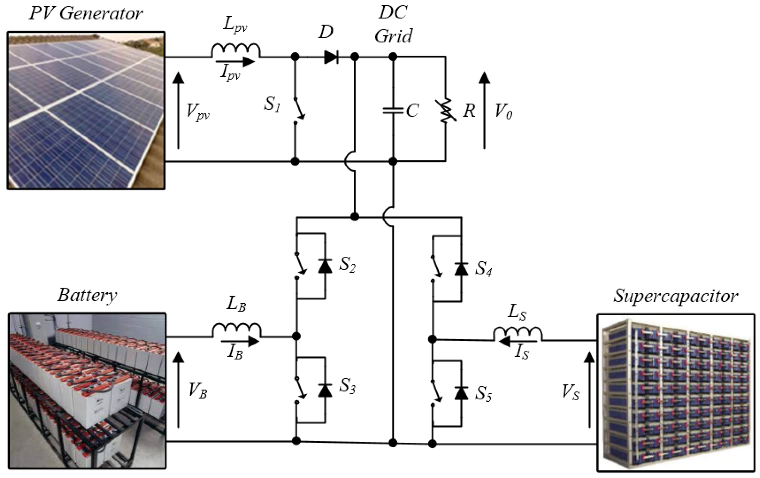
2. DC Electrical Grid Configuration

HESS topologies are categorized into active, semi-active or passive, depending on how storage elements are linked to a continuous bus. Passive HESS refers to energy storage elements that are directly connected to the continuous bus, while active HESS occurs when two energy storage devices are linked via a bidirectional converter to the continuous bus. Figure 1, below, illustrates a stand-alone photovoltaic system involving a PV panel, lithium-ion battery, and SC. It represents the PV generator, battery, and super-capacitor voltages, wherein,   I p v , I B and I S denote, respectively, the PV generator, battery, and supercapacitor currents, and C designates the filter capacitance. As for L p v , L B and L S , they refer to the filter inductance of the boost converter, the battery and the super-capacitor converters, respectively, while   S 1 , S 2 , S 3 , S 4 , and S 5 are the control switches. Bidirectional converters are used by active HESS to maintain the V 0 continuous bus voltage constant. Equation (1) gives the steady-state transfer function of the SC bidirectional converter:
V 0 = d 1 1 d 1 V S
where: d 1 represents the duty cycle of the SC buck-boost converter.
The inductance of the SC buck-boost converter is obtained based on Equation (2):
      L S = d 1 V 0 f   Δ I p v
where f denotes the frequency. The battery inductance calculation is the same as the SC inductance.
This buck-boost converter is utilized to enhance electrical energy flow between the HESS and the DC electrical grid. In the present study, the RAPSA’s total load is introduced as an equivalent DC load with resistance R. The PV, lithium-ion battery, and super-capacity modeling are presented and discussed in several research papers [24,39].
The PV generator is connected to the DC electrical grid through a boost converter, used to extract the PV generator’s maximum power, as controlled by means of an MPPT algorithm. Indeed, the PV generator power is obtained through the following equation:
P p v = N s N p V p v I p v
Moreover, the boost converter transfer function is given by:
V 0 = 1 1 d 2 V p v
where d 2 represents the boost converter duty cycle.
Concerning the boost converter sizing, the inductance, and output capacitor in the function of the desired ripples amplitudes are given by the following equations:
{       L p v = d V p v f   Δ I p v C = d I 0 f   Δ V 0
where I 0 represents the load current.
In general, the capacity of a lithium-ion battery is given by:
C B = t i t f I B 3600 d t
where t i and t f represent the initial and final time, respectively.
The SC is nothing more than a simple capacitor with a large capacity for storing electric charge. In HESS’s validating in PV systems, the SC model is accurate and simple as presented by the following equation:
V S = 1 C S C t i t f I S d t
where C S C represents the SC capacity.
The FLC is deployed to regulate the PV generator using data knowledge [39,40]. This FLC module involves the fuzzification, decision making, and defuzzification phases. Figure 2, below, depicts the FLC block structure, wherein, E ,   C E , and the duty cycle designate the FLC inputs and output. The following equation depicts the FLC inputs:
{ E = P p v ( k ) P p v ( k 1 ) V p v ( k ) V p v ( k 1 ) C E = E ( k ) E ( k 1 )
where k refers to the sample time.
The fuzzification, inference and defuzzification stages are further explained below.
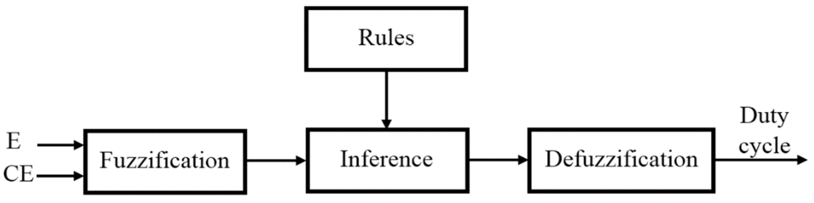
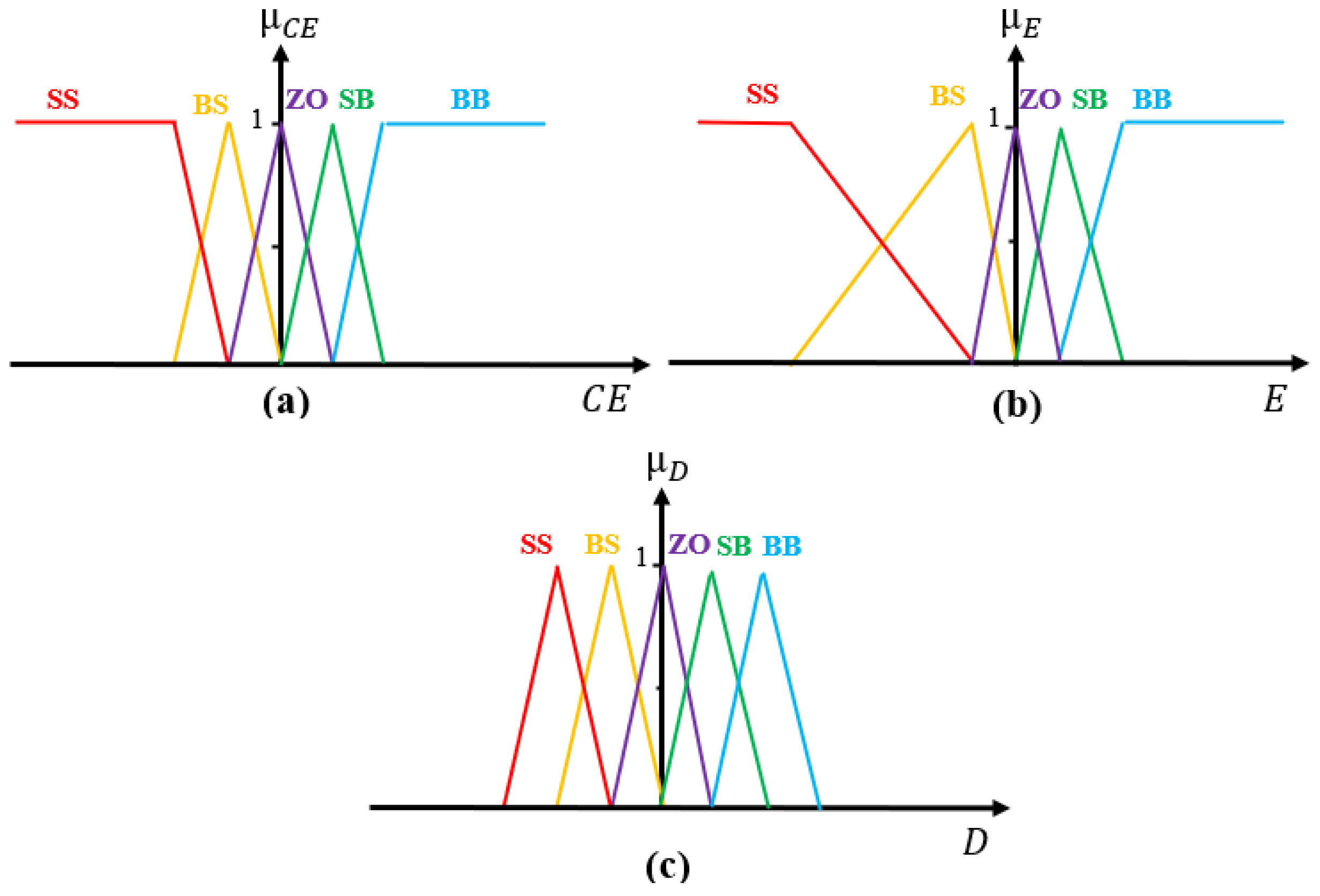
  • Fuzzification: The fuzzification process entails that every variable used to define the control rules need be described by the fuzzy set notations and linguistic labels. Figure 3, below, highlights the MFs of the input and output variables. Each MF comprises five fuzzy sets: SS, BS, ZO, SB, and BB (S and B represent low and high, respectively).
  • Inference: Developing the cartography applying the FLC of a given input to output is referred to as the inference technique. In this study, a Mamdani fuzzy inference is used. Table 2 depicts the relevant associated rules.
  • Defuzzification: The FLC crisp output is computed throughout the defuzzification phase. In our context, a defuzzifier of gravity center type is applied.

3. HESS Control Strategy

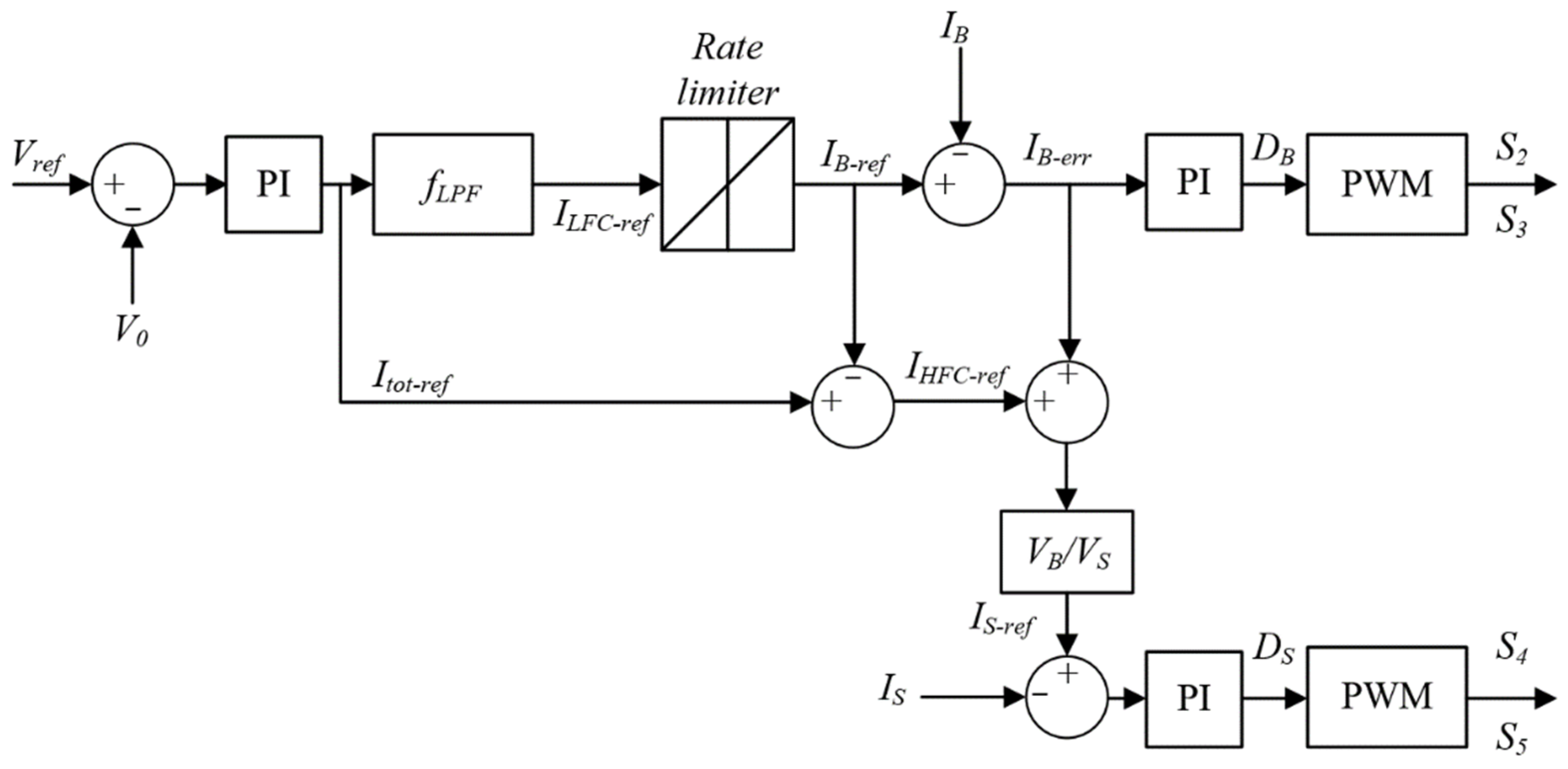
3.1. Conventional HESS Control Strategy

The conventional strategy is described through Figure 4 [41]. The major idea of this management approach consists in enhancing the lithium-ion battery lifetime by reducing the charging- and discharging-associated stress. In this study, the average voltage value is compared to the reference voltage ( V r e f ), while the error is received by the PI controller. The PI controller of the ESS generates the entirety of current amount required. The current I t o t r e f is separated into low/high frequency components. The low-frequency component is depicted through the following expression:
I L F C r e f = f L P F ( I t o t r e f )
where   f L P F ( . ) denotes the function of the low pass filter. At this level, a rate limiter is applied to the low-frequency component to help regulate the battery charge/discharge rates, which yields the reference current of the battery as expressed by:
I B r e f = f R L ( I L F C r e f )
where I B r e f = f R L ( . ) refers to the rate limiter function. The actual battery current I B is compared to the reference, yielding a current error of I B e r r . The duty cycle D B is generated by the PI controller in accordance with the value of I B e r r . The PWM generator provides the battery-switching pulses ( S 2 and S 3 ) according to the duty cycle D B .
Regarding the high-frequency component, it is derived on the basis of the following expression:
I H F C r e f = I t o t r e f I B r e f
Owing to sluggish dynamics, the battery may not monitor the I B r e f immediately. Hence, the battery uncompensated electrical power turns out to be expressed as:
P B u n c o m p = ( I H F C r e f + I B e r r ) V B
Accordingly, the latter is compensated for by the used SC. Therefore, the super-capacitor reference current turns out to be expressed as:
I S r e f = ( I H F C r e f + I B e r r ) V B V S
I S r e f is compared to I S , which provides the D S duty cycle in terms of the PI controller. Thus, the super capacitor switches ( S 4 and S 5 ) can be generated.

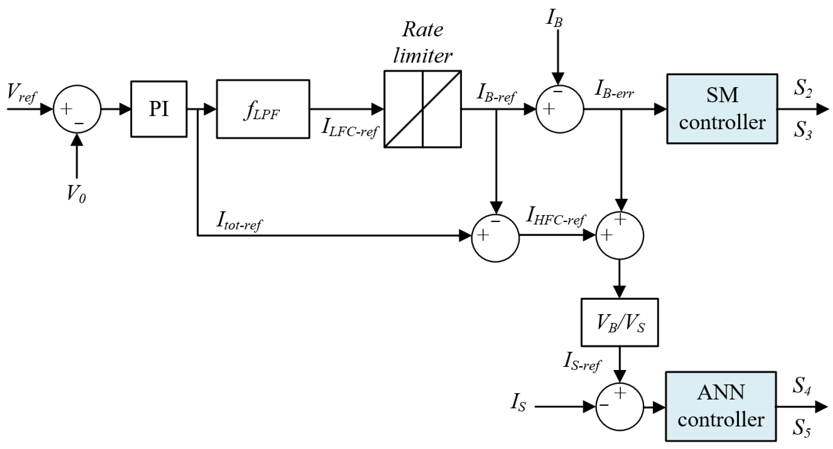
3.2. Proposed HESS Control Strategy

The block diagram of the improved HESS control strategy is presented in Figure 5, below. The suggested control strategy represents an improved version of the method put forward in [41]. In effect, the conventional strategy relies heavily on the PI controller to maintain commutation of the switch. However, the PI controller is not without any drawbacks, which reside mainly in the high initial overshoot, sensitivity to controller gains, and slow response to unexpected disturbances. As to our proposed system, it is designed to maintain a significant power flow and control, and to respond effectively to sudden climatic condition and load variations. For this reason, we consider incorporating intelligent controllers into the proposed strategy to help overcome the classical controllers encountered problems, mainly those associated with the switching problems.
Indeed, the idea of the proposed HESS control strategy rests mainly on the ANN and SM control units. These controllers have several features and tasks to perform, as compared to the classical ones, such as the robustness aspect that takes into account the sudden variations, thereby, improving the storage system performance and lifetime, while avoiding the load’s total disconnection.

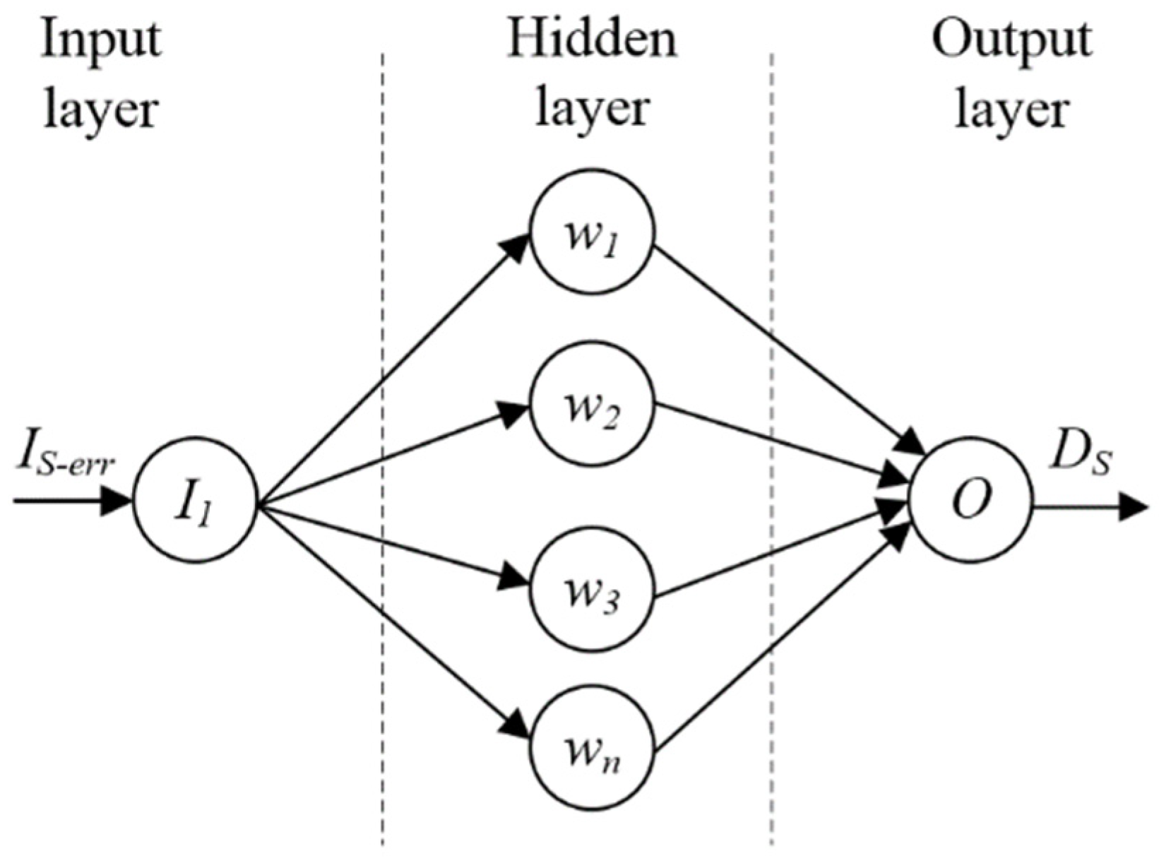
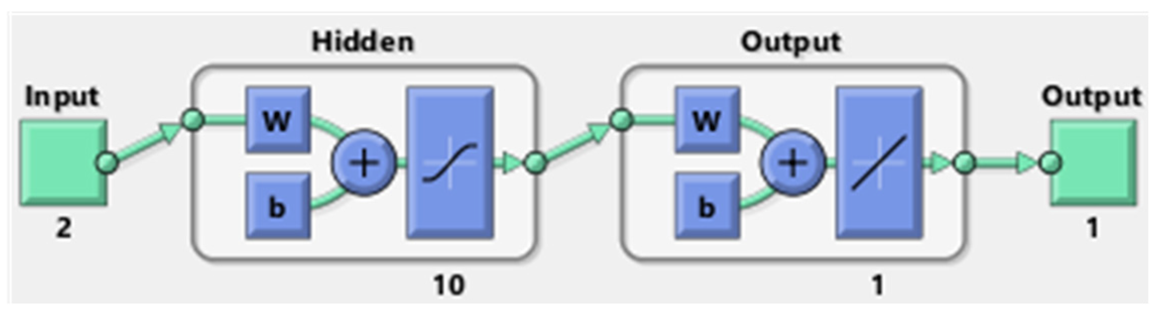
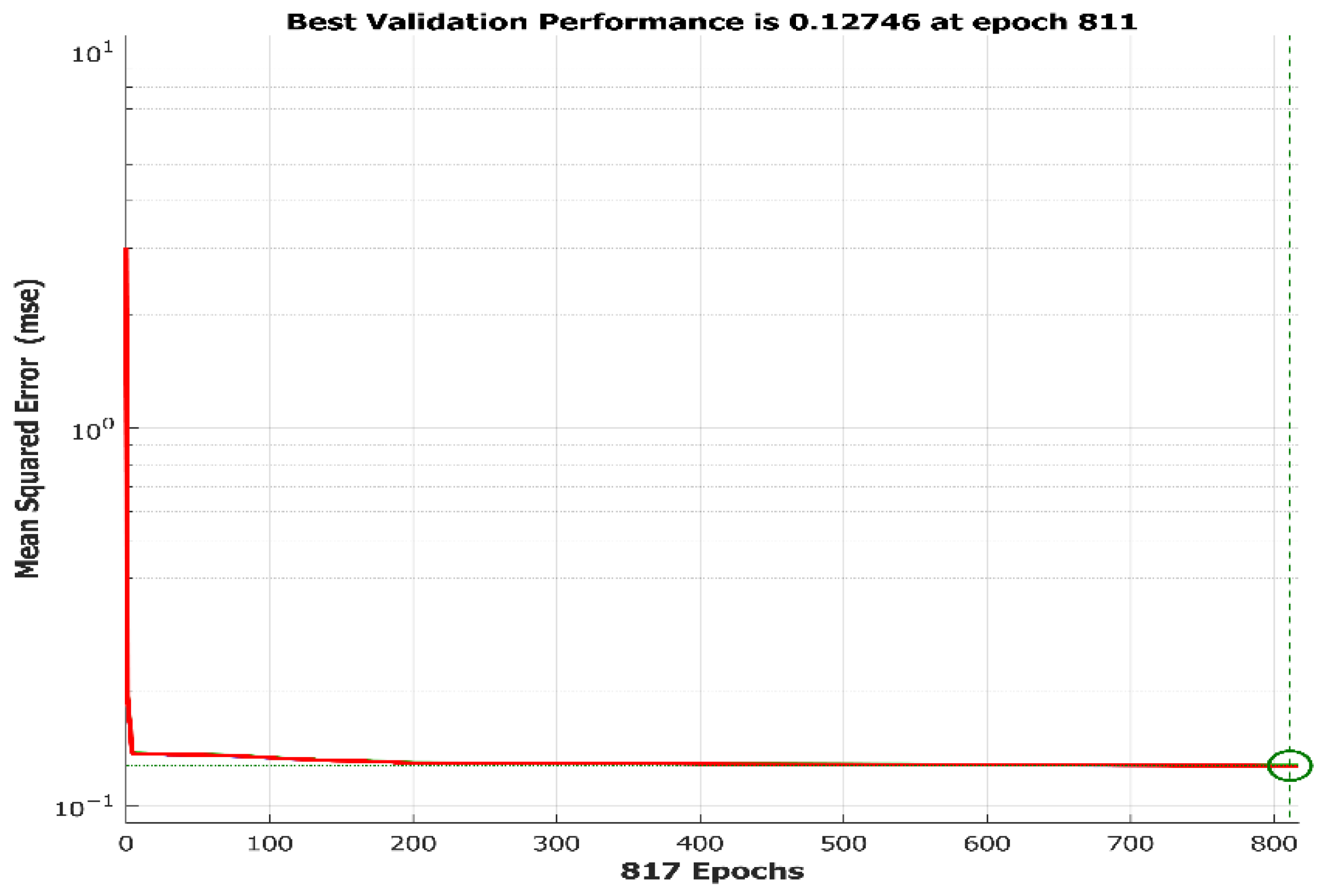
3.2.1. The ANN Controller

The ANN controller has recently gained remarkable interest in the energy-management strategies [39]. The neural network architecture comprises three layers: input, hidden, and output, with each layer involving a neuron (also known as a node) connecting it to the multi-layer networks. It is worth highlighting that the ANN controller’s task encloses two main stages: the training stage and the operational one. The ANN controller modeling design is illustrated in Figure 6, below. Accordingly, the ANN controller-associated input and output aspects are the I S e r r current and D S duty cycle, respectively. Note that the I S e r r current is the difference between the ( I S and I S r e f ) currents.
The ANN model is established by means of the MATLAB/Simulink environment. Figure 7, below, illustrates a feedforward NN model with two neurons in the input layer, ten neurons in the hidden layer, and a single neuron in the output layer. The Levenberg–Marquardt algorithm has been utilized to train a set of duty cycle D S data points based on simulation.
It is also worth underlining that the training performance curve, as appearing in Figure 8, below, illustrates that the MSE attained error is of the rate of 0.127 after 811 epochs.

3.2.2. SM Controller

The VSC associated sliding regimes are distinguishable through the control discontinuity dimension, which helps in specifying a desired system’s dynamic (also dubbed SM). Such dynamics are accomplished by selecting proper variety spaces that provide adequate switching, resultant from the desired behavior of the closed loop systems. Consider, for instance, the following state equation structure [39]:
Y ˙ ( t ) = F Y + B U
where Y stands for the state vector ( Y R n ), and U denotes the control vector ( U R m ). The relevant sliding mode control action turns out to be:
U = U e q + Δ U
where U e q denotes the so-called equivalent control to remain on the sliding surface ( S ( Y ) = 0 ), and Δ U represents the desired term fit for maintaining a stable hybrid system exterior to the sliding surface, particularly convenient for poorly modeled electrical systems and persistent external variations or disturbances.
The S ( Y ) function must be selected to meet such a condition that when S ( Y ) = 0 , Y shifts back or reverts to the target state Y ^ . The SM controllers’ essential premise is to entice the system to reach and remain on the sliding surface, i.e., S ( Y ) and S ˙ ( Y ) must be equal to zero, such as:
S ( Y ) = ( d d Y + λ ) j 1 ( Y ^ Y )
where: j denotes the number of times necessary to generate the derivative surface to gain control, and λ represents a constant that is positive.
Regarding the equivalent control,   S ˙ ( Y ) is defined as:
S ˙ ( Y ) = d S d Y ( F ( Y ) + B ( Y ) U ( t ) ) = 0
Based on the matrix regularity d S d Y B ( Y ) , and given:
U e q = ( d S d Y B ( Y ) ) 1 d S d Y F ( Y )
The control discontinuous term is provided by:
Δ U = ( d S d Y B ( Y ) ) 1 U 0 s i g n ( S )
with: U 0 standing for a positive diagonal matrix.
Considering the following Lyapunov function:
V l ( x ) = 1 2 S T S > 0
The function of time derivative turns out to be:
V ˙ l ( x ) = U 0 | S | < 0
Hence, the control laws (14, 17 and 18) should help maintain the system’s stabilization (13) [42,43]. According to these works, the PI controller is substituted with an SM controller. Consider, for instance, the following sliding function S ( Y ) :
S ( Y ) = ( I B r e f I B ) + λ   ( I B r e f I B ) d t
The relevant switching state equation is provided by:
U = 1 U 0 s i g n ( S )
with: U 0 designating a positive gain maintained by:
{ U = 0 ;   i f S > 0 U = 1 ; i f S < 0

4. Simulation Results

The designed HESS control strategy implementation is administered by relying on MATLAB/Simulink, as depicted in Figure 9, below.
On executing the present work, a PV generator of 5329 W power is applied. The generator englobes four modules connected in series with four parallel strings. With reference to Figure 10, the adapted PV array type is the 1Soltech 1STH-215-P. The entirety of the designed HESS control system’s parameters figure on Table 3.
It is important to note that to testify the advanced architecture’s high performance, the design is compared to a number of renown conventional strategies, while accounting for all possible sudden variations. Actually, it is characterized with the ability to account for any weather condition and load power variations over an enlightened day, as illustrated through Figure 11.
As for Figure 12, it depicts the PV generator’s power and load power profile. Accordingly, the PV generator emanating power proves to be higher at times, and at other times lower than the load generated power over time periods or intervals (6–9 h 11 min, 10–10 h 51 min, 12 h 7 min–13 h 30 min, and 13 h 54 min–16 h 12 min) and (9 h 11 min–10 h, 10 h 51 min–12 h 7 min, 13 h 30 min–13 h 54 min, and 16 h 12 min–18 h), respectively.
Figure 13, below, depicts the PV system as observed under climatic condition as well as load variations. Judging by Figure 13, and considering the instants t1, t2, and t3 characterized with noticeably high weather condition and load variations, one can well confirm and testify the investigated method’s robustness in terms of output voltage, which still proves to be equal to the reference voltage level (400 V), as depicted in Figure 13a. Noteworthy, also, is that the load’s high and low variations are characterized with a great increase and decrease in the load current, respectively, as depicted in Figure 13b. Indeed, the DC voltage peak variations are equal to approximately 1% of the reference voltage. Accordingly, the level of the continuous bus voltage fluctuations remains relatively acceptable and does not seem to affect the accuracy of the investigated HESS control strategy. When demand is unexpectedly reduced, for instance, at the instant t3, the output voltage turns out to be proportionally increased. Based on Figure 13c,d, however, and for the sake of maintaining the output voltage at a 400 V level, the super-capacitor undertakes to momentarily absorb the high-frequency component of excess supply, while the lithium-ion battery current takes a longer lapse to reach a stable state [44,45]. Indeed, the rate of the battery’s charging current is very low. It is also worth noting that the lithium-ion battery’s current stress is still remarkably minimal, meaning that it contributes in enhancing the battery’s life span, as compared to the other energy-management schemes.
When the demand is unexpectedly increased, for instance at instants t1 and t2, the output voltage will decrease proportionately. The supercapacitor would provide the surplus demand for a brief period for a regular voltage level to be maintained at a 400 V level, and divert the component of the low frequency to the lithium-ion battery, as illustrated in Figure 13c. Hence, the battery current discharge stress would be very low, thereby boosting the battery life, as compared to the conventional management strategies.
Figure 14a,b indicate the SOC of the battery and supercapacitor, respectively. Referring to Figure 14, the battery and supercapacitor charge and discharge are maintained in conformity with the advanced HESS control strategy. It is worth highlighting that to demonstrate the robustness of the proposed HESS control strategy, a real climatic conditions profile is necessary to implement with all possible load-variation considerations.
To compare the proposed method’s performance and that of the conventional method, irradiation increase and decrease step scenarios are selected, accounting for a temperature of 25 °C, as illustrated in Figure 15a,b, and a load power of 2703 W, as depicted in Figure 16, wherein the PV tends to vary with variations in climatic conditions.
As illustrated through Figure 17, both methods’ DC bus voltage simulation results are depicted. They illustrate well that the continuous bus voltage tends to increase and decrease proportionately to the increase and decrease in the PV generator’s power. Actually, the super-capacitor’s supply and demand surpluses are momentarily absorbed to continuously maintain the bus voltage at a 400 V level, as illustrated through Figure 17. The low-frequency component is diverted to the battery, thereby, maintaining current stress at a noticeably low level. According to the already displayed results, the designed HESS control strategy appears to offer rather prompt voltage regulation and lower oscillation (zoomed output voltage) than the conventional HESS control strategy.
In addition, a step increase and a step decrease in the load power are also observed, considering the standard climatic conditions (25 °C and 1000 W/m2), as illustrated in Figure 18. Accordingly, the PV generator is set to its maximum power. Figure 19 highlights the continuous bus-voltage simulation results relevant to both of the conventional and proposed methods. Accordingly, the DC bus-voltage tends to decrease and increase in proportion with the increase and decrease in load power. The supercapacitor undertakes to supply the demand and supply surpluses for a very short time lapse, and gradually returns the steady-state current to the lithium-ion battery, thus maintaining the battery current stress to a very low minimal level.
Actually, it is this very low current stress that helps enhance the battery’s life cycle. According to the attained simulation results, the suggested strategy proves to demonstrate a faster DC bus voltage regulation than the conventional strategy, as highlighted through Figure 19, below (zoomed are). In sum, considering the possibly recurrent climatic conditions and load variations, the SC undertakes to momentarily absorb the high-frequency component. As regards the low-frequency component, it is diverted to the lithium-ion battery, thereby decreasing the battery charging and discharging current peaks, and increasing the battery’s life cycle, as compared to the other conventional management strategies. The load power-supply continuity is ensured, considering the climatic-condition variations, thanks to the implementation of the super-capacitor. Additionally, the proposed strategy appears to guarantee a rather swift voltage regulation and lower oscillation levels in relation to the conventional method.

5. Conclusions

In this paper, the investigated HESS control rests on monitoring the low-frequency and high-frequency power components of the demand/generation mismatch, while deploying the battery current error to achieve the targeted results. For the purpose of maintaining robustness of the investigated HESS control, taking into account the sudden scenarios of unexpected climatic-condition and load variations, SM and ANN controllers are utilized to boost the storage system’s performance and lifetime, while avoiding the load’s total disconnection. Compared to the already-existing schemes, the proposed strategy turns out to be easier to implement and involves less processing. Considering the climatic-condition and load variations, the peak variation in continuous bus voltage is approximately equal to 1% of the reference voltage, thus maintaining the continuous bus voltage fluctuation rate at a relatively acceptable level. It does not affect the accuracy of the investigated HESS control strategy as compared to the other HESS strategies. Taking into account these variations, the SC undertakes to momentarily absorb the high-frequency component. As regards the low-frequency component, it is diverted to the lithium-ion battery, thereby decreasing the battery charging and discharging current peaks, and increasing the battery’s life cycle, as compared to the other conventional management strategies. Actually, the preconized HESS control strategy, jointly associating the PV generator and FLC as well as the SC and lithium-ion battery modules, has been implemented by means of MATLAB/Simulink. Finally, the reached simulation results turn out to highlight the investigated HESS control strategy’s outperformance, efficiency, and supremacy over the conventional ones in terms of promptly continuous bus voltage regulation, low oscillations, as well as capability to boost the battery’s lifetime, and maintain the PV system’s continuity and persistence. The proposed work can be expanded to other hybrid energy systems using machine and deep learning in the control strategy in light of future directions.

Author Contributions

Conceptualization, M.A.Z., T.G., F.B.S. and H.H.A.; methodology, M.A.Z., T.G., K.A. and F.B.S.; software, M.A.Z., B.M.A. and K.A.; validation, M.A.Z., T.G., K.A., B.M.A. and A.A. and H.H.A.; formal analysis, M.A.Z. and A.A.; investigation, M.A.Z., K.A. and A.A.; writing—original draft preparation, M.A.Z., T.G. and B.M.A.; supervision, T.G. and A.T.; project administration, T.G.; funding acquisition, T.G. All authors have read and agreed to the published version of the manuscript.

Funding

This research was funded by the Deanship of the Scientific Research of the University of Ha’il, Saudi Arabia (project: RG-20 059).

Institutional Review Board Statement

Not applicable.

Informed Consent Statement

Not applicable.

Data Availability Statement

Not applicable.

Conflicts of Interest

The authors declare no conflict of interest.

Abbreviations

RAPSAsRemote area power system applications
HESSHybrid energy storage system
PVPhotovoltaic
SCSuper capacitor
DCDirect current
MPPTMaximum power point tracking
FLCFuzzy logic controller
EMAEnergy management algorithm
MPCModel predictive controller
MFMembership function
ANNArtificial neural network
SMSliding mode
VSCVariable structure control

References

  1. Twidell, J.W.; Weir, A.D. Renewable Energy Resources; Taylor and Francis: Abingdon, UK, 2015. [Google Scholar]
  2. Benson, C.L.; Magee, C.L. On improvement rates for renewable energy technologies: Solar PV, wind turbines, capacitors, and batteries. Renew. Energy 2014, 68, 745–751. [Google Scholar] [CrossRef]
  3. Svazas, M.; Navickas, V.; Bilan, Y.; Vasa, L. The Features of the Shadow Economy Impact’ on Biomass Energy Sector. Energies 2022, 15, 2932. [Google Scholar] [CrossRef]
  4. Khodayar, M.E.; Barati, M.; Shahidehpour, M. Integration of high reliability distribution system in microgrid operation. IEEE Trans. Smart Grid 2012, 3, 1997–2006. [Google Scholar] [CrossRef]
  5. Brown, H.E.; Suryanarayanan, S.; Natarajan, S.A.; Rajopadhye, S. Improving reliability of islanded distribution systems with distributed renewable energy resources. IEEE Trans. Smart Grid 2012, 3, 2028–2038. [Google Scholar] [CrossRef]
  6. Quiggin, D.; Cornell, S.; Tierney, M.; Buswell, R.A. simulation and optimization study: Towards a decentralized microgrid, using real world fluctuation data. Energy 2012, 41, 549–559. [Google Scholar] [CrossRef] [Green Version]
  7. Ton, D.T.; Wang, W.T.P. A more resilient grid: The U.S. department of energy joins with stakeholders in an R&D plan. IEEE Power Energy Mag. 2015, 13, 26–34. [Google Scholar]
  8. Vandoorn, T.L.; Meersman, B.; De Kooning, J.D.M.; Vandevelde, L. Transition from islanded to grid-connected mode of microgrids with voltage-based droop control. IEEE Trans. Power Syst. 2013, 28, 2545–2553. [Google Scholar] [CrossRef] [Green Version]
  9. Giacomoni, A.M.; Goldsmith, S.Y.; Amin, S.M.; Wollenberg, B.F. Analysis, modeling, and simulation of autonomous microgrids with a high penetration of renewables. In Proceedings of the 2012 IEEE Power and Energy Society General Meeting, San Diego, CA, USA, 22–26 July 2012. [Google Scholar]
  10. Som, T.; Chakraborty, N. Studies on economic feasibility of an autonomous power delivery system utilizing alternative hybrid distributed energy resources. IEEE Trans. Power Syst. 2014, 29, 172–181. [Google Scholar] [CrossRef]
  11. Moseley, P.T. Energy storage in remote area power supply (RAPS) systems. J. Power Sources 2006, 155, 83–87. [Google Scholar] [CrossRef]
  12. Kellogg, W.; Nehrir, M.H.; Venkataramanan, G.; Gerez, V. Generation unit sizing and cost analysis for stand-alone wind, photovoltaic, and hybrid wind/PV systems. IEEE Trans. Energy Convers 1998, 13, 70–75. [Google Scholar] [CrossRef]
  13. Mendis, N.; Muttaqi, K.M.; Perera, S. Active power management of a supercapacitor-battery hybrid energy storage system for standalone operation of DFIG based wind turbines. In Proceedings of the 2012 IEEE Industry Applications Society Annual Meeting, Las Vegas, NV, USA, 7–11 October 2012. [Google Scholar]
  14. Sathish Kumar, R.; Sathish Kumar, K.; Mishra, M.K. Dynamic energy management of micro grids using battery super capacitor combined storage. In Proceedings of the 2012 Annual IEEE India Conference (INDICON), Kochi, India, 7–9 December 2012; pp. 1078–1083. [Google Scholar]
  15. Glavin, M.; Chan, P.; Armstrong, S.; Hurley, W. A stand-alone photovoltaic supercapacitor battery hybrid energy storage system. In Proceedings of the 2008 13th International Power Electronics and Motion Control Conference, Poznan, Poland, 1–3 September 2018; pp. 1688–1695. [Google Scholar]
  16. Şahin, M.E.; Blaabjerg, F.A. Hybrid PV-battery/supercapacitor system and a basic active power control proposal in MATLAB/Simulink. Electronics 2020, 9, 129. [Google Scholar] [CrossRef] [Green Version]
  17. Hredzak, B.; Agelidis, V.; Jang, M. A model predictive control system for a hybrid battery-ultracapacitor power source. IEEE Trans. Power Electron. 2014, 29, 1469–1479. [Google Scholar] [CrossRef]
  18. Lahyani, A.; Venet, P.; Guermazi, A.; Troudi, A. Battery/supercapacitors combination in uninterruptible power supply (UPS). IEEE Trans. Power Electron. 2013, 28, 1509–1522. [Google Scholar] [CrossRef]
  19. Wei, L.; Joos, G.; Belanger, J. Real-time simulation of a wind turbine generator coupled with a battery supercapacitor energy storage system. IEEE Trans. Power Electron. 2010, 57, 1137–1145. [Google Scholar] [CrossRef]
  20. Ortuzar, M.; Moreno, J.; Dixon, J. Ultracapacitor-based auxiliary energy system for an electric vehicle: Implementation and evaluation. IEEE Trans. Ind. Electron. 2007, 54, 2147–2156. [Google Scholar] [CrossRef]
  21. Teleke, S.; Baran, M.; Bhattacharya, S.; Huang, A. Rule-based control of battery energy storage for dispatching intermittent renewable sources. IEEE Trans. Sustain. Energy 2010, 1, 117–124. [Google Scholar] [CrossRef]
  22. Gee, A.M.; Robinson, F.V.P.; Dunn, R.W. Analysis of battery lifetime extension in a small-scale wind-energy system using supercapacitors. IEEE Trans. Energy Convers. 2013, 28, 24–33. [Google Scholar] [CrossRef]
  23. Chong, L.W.; Wong, Y.W.; Rajkumar, R.K.; Rajkumar, R.K.; Isa, D. Hybrid energy storage systems and control strategies for stand-alone renewable energy power systems. Renew. Sustain. Energy Rev. 2016, 66, 174–189. [Google Scholar] [CrossRef]
  24. Javed, K.; Ashfaq, H.; Singh, R.; Hussain, S.M.; Ustun, T.S. Design and performance analysis of a stand-alone PV system with hybrid energy storage for rural India. Electronics 2019, 8, 952. [Google Scholar] [CrossRef] [Green Version]
  25. Jing, W.; Lai, C.H.; Wong, S.H.W.; Wong, M.L.D. Battery-supercapacitor hybrid energy storage system in standalone DC microgrids: A review. IET Renew. Power Gener. 2017, 11, 461–469. [Google Scholar] [CrossRef]
  26. Muqeet, H.A.; Javed, H.; Akhter, M.N.; Shahzad, M.; Munir, H.M.; Nadeem, M.U.; Bukhari, S.S.H.; Huba, M. Sustainable Solutions for Advanced Energy Management System of Campus Microgrids: Model Opportunities and Future Challenges. Sensors 2022, 22, 2345. [Google Scholar] [CrossRef]
  27. Hredzak, B.; Agelidis, V. Model predictive control of a hybrid battery-ultracapacitor power source. In Proceedings of the 7th International Power Electronics and Motion Control Conference, Harbin, China, 2–5 June 2012; pp. 2294–2299. [Google Scholar]
  28. Hredzak, B.; Agelidis, V. Direct current control of a battery ultracapacitor power supply. In Proceedings of the IECON 2012—38th Annual Conference on IEEE Industrial Electronics Society, Montreal, QC, Canada, 25–28 October 2012; pp. 4024–4028. [Google Scholar]
  29. Zhang, J.; Huang, L.; Shu, J.; Wang, H.; Ding, J. Energy management of PV-diesel-battery hybrid power system for island stand-alone micro-grid. Energy Procedia 2017, 105, 2201–2206. [Google Scholar] [CrossRef]
  30. Aziz, A.S.; Tajuddin, M.F.N.; Adzman, M.R.; Ramli, M.A.; Mekhilef, S. Energy management and optimization of a PV/diesel/battery hybrid energy system using a combined dispatch strategy. Sustainability 2019, 11, 683. [Google Scholar] [CrossRef] [Green Version]
  31. Emara, D.; Ezzat, M.; Abdelaziz, A.Y.; Mahmoud, K.; Lehtonen, M.; Darwish, M.M. Novel control strategy for enhancing microgrid operation connected to photovoltaic generation and energy storage systems. Electronics 2021, 10, 1261. [Google Scholar] [CrossRef]
  32. Wang, Y.; Jiao, X. Dual Heuristic Dynamic Programming Based Energy Management Control for Hybrid Electric Vehicles. Energies 2022, 15, 3235. [Google Scholar] [CrossRef]
  33. Dai, K.; Zhang, C.; Li, Q.; Huang, X.; Zhang, H. An Adaptive Energy Management Strategy for Simultaneous Long Life and High Wake-Up Success Rate of Wireless Sensor Network Nodes. Energy Technol. 2021, 9, 2100522. [Google Scholar] [CrossRef]
  34. Gharibeh, H.F.; Yazdankhah, A.S.; Azizian, M.R.; Farrokhifar, M. Online energy management strategy for fuel cell hybrid electric vehicles with installed PV on roof. IEEE Trans. Ind. Appl. 2021, 57, 2859–2869. [Google Scholar] [CrossRef]
  35. Ravada, B.R.; Tummuru, N.R.; Ande, B.N.L. Photovoltaic-Wind and Hybrid Energy Storage Integrated Multisource Converter Configuration-Based Grid-Interactive Microgrid. IEEE Trans. Ind. Electron. 2020, 68, 4004–4013. [Google Scholar] [CrossRef]
  36. Lu, X.; Zhang, X.; Zhang, G.; Fan, J.; Jia, S. Neural network adaptive sliding mode control for omnidirectional vehicle with uncertainties. ISA Trans. 2019, 86, 201–214. [Google Scholar] [CrossRef]
  37. Chu, Y.; Fei, J.; Hou, S. Adaptive global sliding-mode control for dynamic systems using double hidden layer recurrent neural network structure. IEEE Trans. Neural Netw. Learn. Syst. 2019, 31, 1297–1309. [Google Scholar] [CrossRef]
  38. Ahmed, S.; Muhammad Adil, H.M.; Ahmad, I.; Azeem, M.K.; Huma, Z.; Abbas Khan, S. Supertwisting sliding mode algorithm based nonlinear MPPT control for a solar PV system with artificial neural networks based reference generation. Energies 2020, 13, 3695. [Google Scholar] [CrossRef]
  39. Zdiri, M.A.; Khelifi, B.; Ben Salem, F.; Hadj Abdallah, H. A Comparative Study of Distinct Advanced MPPT Algorithms for a PV Boost Converter. Int. J. Renew. Energy Res. 2021, 11, 1156–1165. [Google Scholar]
  40. Zdiri, M.A.; Ben Ammar, M.; Ben Salem, F.; Hadj Abdallah, H. PWM-VSI Diagnostic and Reconfiguration Method Based on Fuzzy Logic Approach for SSTPI-Fed IM Drives under IGBT OCFs. Math. Probl. Eng. 2021, 2021, 9505845. [Google Scholar] [CrossRef]
  41. Kollimalla, S.K.; Mishra, M.K.; Narasamma, N.L. Design and analysis of novel control strategy for battery and supercapacitor storage system. IEEE Trans. Sustain. Energy 2014, 5, 1137–1144. [Google Scholar] [CrossRef]
  42. Utkin, V. Sliding Mode Control Design Principles and Application to Electric Drives. IEEE Trans. Ind. Appl. 1993, 40, 23–36. [Google Scholar] [CrossRef] [Green Version]
  43. Young, K.D.; Utkin, V.I.; Ozguner, U. A control engineers guide to sliding mode control. IEEE Trans. Control Syst. Technol. 1999, 7, 328–342. [Google Scholar] [CrossRef] [Green Version]
  44. Divakaran, A.M.; Minakshi, M.; Bahri, P.A.; Paul, S.; Kumari, P.; Divakaran, A.M.; Manjunatha, K.N. Rational design on materials for developing next generation lithium-ion secondary battery. Prog. Solid State Chem. 2021, 62, 100298. [Google Scholar] [CrossRef]
  45. Divakaran, A.M.; Hamilton, D.; Manjunatha, K.N.; Minakshi, M. Design, development and thermal analysis of reusable Li-ion battery module for future mobile and stationary applications. Energies 2020, 13, 1477. [Google Scholar] [CrossRef] [Green Version]
Figure 1. A typical PV-based DC electrical grid design.
Energies 15 04099 g001
Figure 2. Diagram of the FLC block.
Energies 15 04099 g002
Figure 3. The MF’s inputs and output.
Energies 15 04099 g003
Figure 4. Conventional HESS strategy scheme.
Energies 15 04099 g004
Figure 5. Proposed HESS strategy scheme.
Energies 15 04099 g005
Figure 6. ANN controller block diagram.
Energies 15 04099 g006
Figure 7. ANN controller using the MATLAB NNET toolbox.
Energies 15 04099 g007
Figure 8. Performance of the ANN controller.
Energies 15 04099 g008
Figure 9. Simulink modeling of the advanced strategy.
Energies 15 04099 g009
Figure 10. The PV generator’s characteristics.
Energies 15 04099 g010
Figure 11. Climatic-condition and load-current variations observed over a 6–18 h span. Legend: (a) irradiation; (b) temperature; and (c) load current.
Energies 15 04099 g011
Figure 12. PV generator and load power profiles.
Energies 15 04099 g012
Figure 13. Simulation results of the HESS under climatic condition and load variations. Legend: (a) output voltage; (b) load current; (c) lithium-ion battery current; and (d) SC current.
Energies 15 04099 g013
Figure 14. Simulation results of the SC and battery SOC. Legend: (a) battery SOC; and (b) SC SOC.
Energies 15 04099 g014
Figure 15. Climatic-condition variations. Legend: (a) irradiation; and (b) temperature.
Energies 15 04099 g015
Figure 16. The PV generator and load power.
Energies 15 04099 g016
Figure 17. The DC bus voltage associated with both methods.
Energies 15 04099 g017
Figure 18. The PV generator and load power.
Energies 15 04099 g018
Figure 19. Both methods’ associated DC bus voltage levels.
Energies 15 04099 g019
Table 1. The SCs versus batteries related performance.
SCLead Acid BatteryLithium-Ion Battery
Density of specific energy (Wh/kg)1–1010–100150–200
Density of specific power (W/kg)<10,000<1000<2000
Life-cycle>500,00010005000
Charge–discharge efficiency (%)85–9870–8599
Discharge time0.3–30 s0.3–3 h0.3–3 h
Quick charge time0.3–30 s1–5 h0.5–3 h
Table 2. Table of FLC rules.
CEE
SSBSZOSBBB
SSBBBBSBBBBB
BSBBSBSBSBBB
ZOBSBSZOSBSB
SBSSBSBSBSSS
BBSSSSBSSSSS
Table 3. The proposed HESS parameters.
PV Generator Parameters
Maximum power5329 W
Voltage at MPP181.5 V
Current at MPP39.2 A
PV module series and parallel stringsNs = 5, Np = 5
DC/DC converter and line parameters
DC bus voltage 400 V
S1, S2, S3, S4 and S5IGBT/Diode
Switching frequency10 kHz
Capacitor (C)3300 µF
DC/DC converter inductorLpv = 5 mH, LB = 2 mH, LS = 1 mH
Super capacitor parameters
Voltage and Capacity2.7 V, 310 F
Module and array (Nsc = 5, Npc = 2) × 20 series
Battery parameters
Battery modelLithium-ion
Voltage220 V
Capacity50 Ah
Publisher’s Note: MDPI stays neutral with regard to jurisdictional claims in published maps and institutional affiliations.

