Article

Design and Analysis of Novel Synchronous Motion Technique for a Multi-Module Permanent Magnet Linear Synchronous Motor

School of Mechanical and Electrical Engineering, Wuhan University of Technology, Wuhan 430070, China
*
Author to whom correspondence should be addressed.
Energies 2022, 15(10), 3617; https://doi.org/10.3390/en15103617
Submission received: 2 April 2022 / Revised: 7 May 2022 / Accepted: 12 May 2022 / Published: 15 May 2022
(This article belongs to the Special Issue Design, Analysis and Control of Permanent Magnet Machines)

Abstract

:
Traditionally, synchronous motion among multi-module permanent magnet linear synchronous motors (PMLSM) has been achieved by adopting independent power supply and control. This method, however, requires multiple drivers and has control time delays. This paper proposes a novel approach to overcome these drawbacks, in which the windings of each module connect in series. Aiming at this electrical connection, we conduct research on electromagnetic and synchronous characteristics. Firstly, a two-module PMLSM is created as a case. Secondly, accurate mathematical models considering coupling inductance for this novelty structure are established, which are essential to driving control. The synchronous characteristics of the two-module are then compared with the independent control of each module. Furthermore, this comparison is conducted under both external and no external disturbance. Finally, experimental results verify the correctness of mathematical models, and reveal that this novel technique could eliminate control time delay and acquire better anti-disturbance performance between the two-module.

1. Introduction

Owing to the development of mechanical equipment toward larger size, heavy load, and higher efficiency, the control of a single driver cannot meet the requirement of accurate control, adequate driving power, and excellent dynamic performance [1,2,3]. Therefore, the synchronous motion is applied in large-scale mechanical equipment, such as embroidery machines [4] and CNC machine tools [5]. To realize the synchronous motion, various strategies have been proposed. Traditionally, these strategies can be classified into mechanical synchronization [6,7,8] and electrical synchronization [9,10].
The mechanical synchronization works in a simple way, where the single motor actuates the long axis to realize synchronous motion through the synchronous belt. However, the deformation and vibration of the axis are inevitably caused by a long span and dynamic unbalance, respectively.
Contrarily, electrical synchronization is another synchronous motion of the multi-motor, substituted for the synchronous belt to avoid the mentioned disadvantages [11,12]. Various control algorithms are used to enhance multi-motor synchronous accuracy [13,14,15,16] and dynamic response under varying loads [17]. However, these synchronous motions of the multi-motor require multiple drivers, thus leading to rising driver cost. Meanwhile, the required number of controller interfaces increases with the number of drivers via parallel processing, which means that the cost of the controller increases, and the anti-interference of the controller decreases. In order to overcome the above drawbacks, EtherCAT bus is employed to achieve communication between each driver through serial processing [18]. Although the number of the controller interfaces does not increase, the communication delay time cannot be completely eliminated.
Recently, the topology structure of the multi-module has attracted researcher interest. In [19], the research of permanent magnet machines with modular structure focuses on the influence of total magnet flux density. In [20], the coupling force between adjacent modules affecting the whole motor’s detent force has been investigated. In addition, a modular stator with an appropriate slot-pole combination exhibits higher torque and lower torque ripple verified by FEM [21]. These studies corroborate the advantages of the modular structure, which neglect the effects of the coupling inductance. In [22], cross-coupling inductance characteristics for the multi-segments that are electrically independent of each other have been studied. Furthermore, the synchronous motions of the multi-module adopt independent vector control strategies and inverters. In [23], each module of the multi-module PMLSM is driven and controlled independently, forming an independent drive unit. However, the above research only focuses on independent control of the multi-module and how to reduce thrust ripple.
In this paper, we replaced multi-motor synchronous motion with multi-module synchronous motion. The main difference from the conventional synchronous control is that the windings of the multi-module are connected in series, not electrical independence. Therefore, we can realize the objective of multi-module synchronous motion with one driver and non-time delay. To confirm the feasibility of the proposed new idea, a 24s/28p two-module PMLSM is made as an example to test the synchronous characteristics and electromagnetic performance.
Based on the above analysis, the two-module series power supply is a new synchronous motion. First, corresponding control strategies ought to be formulated according to this particular power supply mode. Accurate mathematical models are crucial to the whole motor drive control. The mathematical models of flux linkage, voltage, thrust, and power are derived by referring to the one-module PMLSM. Furthermore, due to the imbalanced mutual inductance of the interior module and coupling inductance between each module, these influences on the whole motor need further investigation. Moreover, the effect of the coupling inductance may become aggravated, especially in heavy load and magnetic saturation conditions. Consequently, mathematical models should consider the coupling inductance between each module.
This paper is organized as follows: the topology structure of the two-module PMLSM is introduced in Section 2. In Section 3, the mathematical models of the flux linkage, voltage, power, and thrust for this two-module motor are built. Then, the performance of the synchronous motion and electrical characteristics are fully discussed by tests and FEAM in Section 4. Finally, the corresponding results are presented in Section 5.

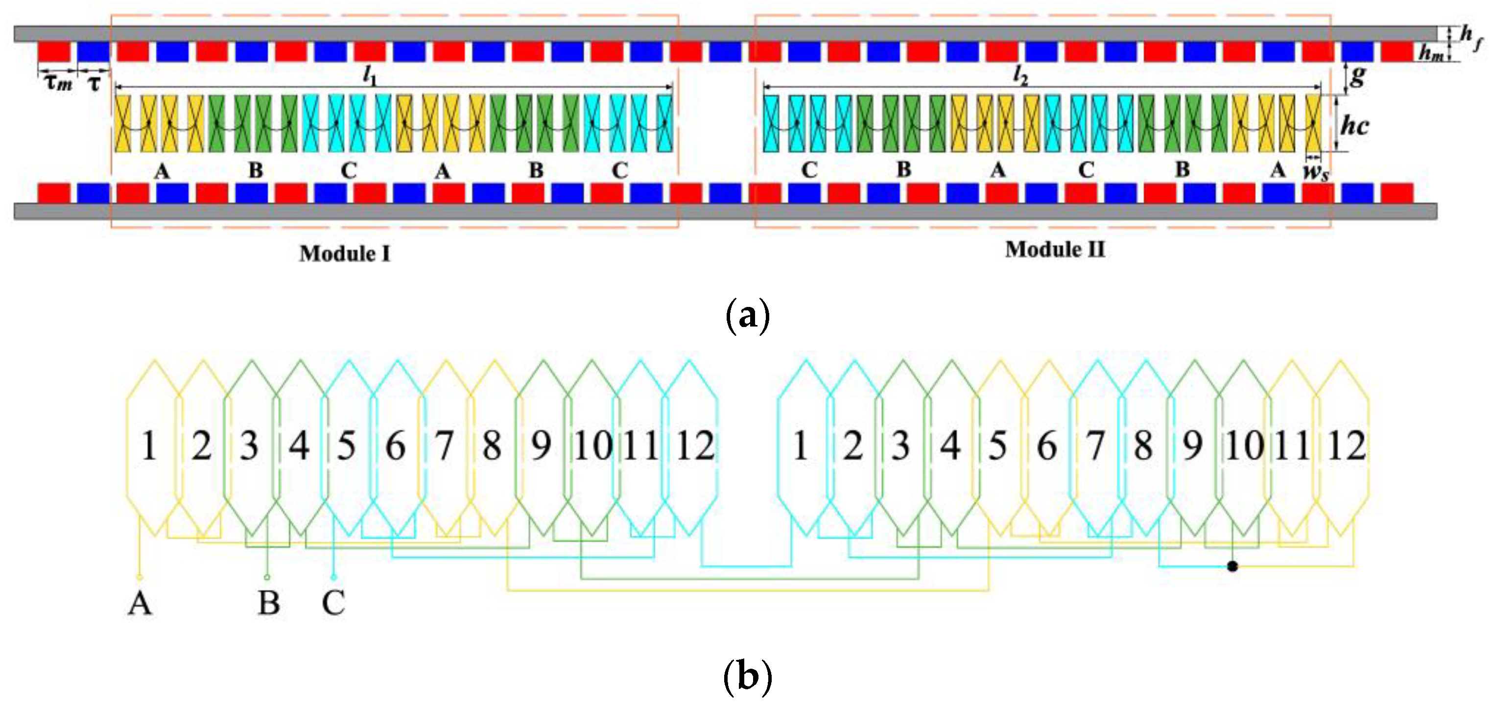
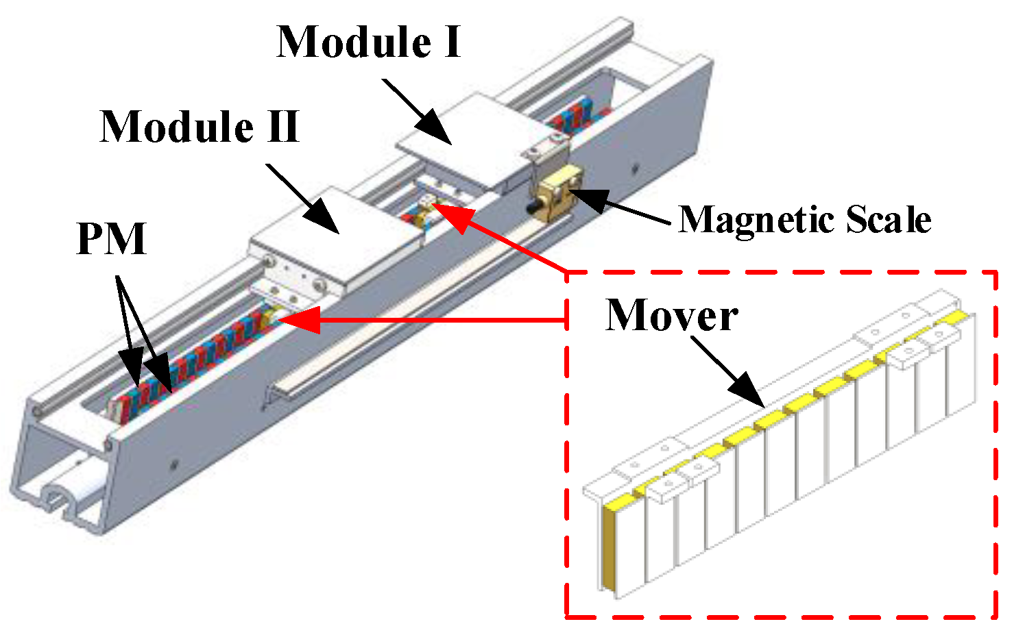
2. Motor Topology Structure

The ironless PMLSM has the merits of low thrust ripple and fast response. Therefore, we designed a two-module ironless PMLSM. Figure 1 shows the 3-D view of a two-module PMLSM. It has two short primaries and one long secondary. Two moving primaries consist of air-core-concentrated windings and brackets printed by nylon material. The same phase windings of the two primaries connect in series. All the coils are wounded in nylon slots and are potted with epoxy resin. Furthermore, the three-phase windings of this motor adopt a star connection. The secondary has two permanent magnet (PM) rows and back-irons, forming a two-sided structure. The PMs are magnetized in the alternate direction.
This two-module PMLSM is developed from a one-module PMLSM. Therefore, the design means of each module are according to the normal PMLSM. To obtain the same electromagnetic force, the parameters of each module should be the same. The distance between the two-modules relies on the winding arrangement of each module. As shown in Figure 2b, the two-module has symmetrical winding arrangements. The detailed parameters and dimensions are illustrated in Table 1 and Figure 2.

3. Mathematical Models of the Two-Module PMLSM

The two-module PMLSM can also be applied to classical vector control strategies. However, the coupling inductances between each module have an effect on winding flux linkage. Therefore, the mathematical models of the two-module differ from the one-module PMLSM. The mathematical model must be first derived before studying the vector control strategy.
To better simplify the analysis and to demonstrate the mathematical essence of the two-module PMLSM, the assumptions can be listed as follows:
(1)
the three-phase windings are symmetrical, differing from each other by 120 degrees in space;
(2)
the magnetic circuit nonlinearity and PM eddy current loss are neglected;
(3)
flux linkage produced by windings and PMs is sinusoidal;
(4)
the temperature influence on electromagnetic parameters is dismissed.

3.1. Three-Phase Flux Linkage

The magnetic circuit saturation is not taken into account based on the above assumptions. According to the superposition principle of the linear system, flux linkage is generated from the PMs and armature currents. Owing to the same phase of each module connected in series, the three-phase flux linkage expression of the two-module can be written as [24]:
Ψ = L I + Ψ f
where Ѱ is the column vector of the two-module flux linkage, Ѱf is the column vector of the two-module flux linkage produced by PM, I is the column vector of the two-module current, and L is the inductance matrix, including coupling inductance between the two-module. They can be written as:
Ψ = [ ψ A 1   ψ B 1   ψ C 1   ψ A 2   ψ B 2   ψ C 2 ] T
I = [ i A   i B   i C   i A   i B   i C ] T
Ψ f = ψ P M A 1   ψ P M B 1   ψ P M C 1   ψ P M A 2   ψ P M B 2   ψ P M C 2 T
L = [ L A 1 A 1 M A 1 B 1 M A 1 C 1 M B 1 A 1 L B 1 B 1 M B 1 C 1 M C 1 A 1 M C 1 B 1 L C 1 C 1 M A 1 A 2 M A 1 B 2 M A 1 C 2 M B 1 A 2 M B 1 B 2 M B 1 C 2 M C 1 A 2 M C 1 B 2 M C 1 C 2 M A 2 A 1 M A 2 B 1 M A 2 C 1 M B 2 A 1 M B 2 B 1 M B 2 C 1 M C 2 A 1 M C 2 B 1 M C 2 C 1 L A 2 A 2 M A 2 B 2 M A 2 C 2 M B 2 A 2 L B 2 B 2 M B 2 C 2 M C 2 A 2 M C 2 B 2 L C 2 C 2 ]

3.2. Three-Phase Winding Terminal Voltage

Based on Kirchhoff’s voltage law and Faraday’s induction law [23], the three-phase voltage of each module can be expressed as
U = E + R I
where U is the column vector of the two-module terminal voltage, E is the column vector of two-module induced EMF, and R is the two-module resistance matrix. They can be written as
U = [ u A 1   u B 1   u C 1   u A 2   u B 2   u C 2 ] T
E = d Ψ d t
R = [ R A 1 0 0 0 0 0 0 R B 1 0 0 0 0 0 0 R C 1 0 0 0 0 0 0 R A 2 0 0 0 0 0 0 R B 2 0 0 0 0 0 0 R C 2 ]

3.3. Input Power

The input power of this motor from the driver is determined as follows:
P = j = A B , C u j i j
where uj is the three-phase terminal voltage of the whole motor, and ij is the three-phase current of the whole motor.
On substituting (1) into (7), the input power can be obtained [25]:
P = P c u + d W / d t + P E M
where
P c u = j = A B , C ( R j 1 + R j 2 ) i j 2
P E M = 1 2 k = A B , C n = 1 2 ( d L k n k n d t + d M k 1 k 2 d t ) i k 2 + k j = A B B C , A C n = 1 2 m = 1 2 d M k m j n d t i k i j + k = A B , C n = 1 2 d ψ P M k n d t i k
d W d t = d d t ( 1 2 k = A B , C n = 1 2 ( L k n k n + M k 1 k 2 ) + k j = A B B C , A C n = 1 2 m = 1 2 M k m j n i k i j )
where P is the input power of the entire motor, PEM is the electromagnetic power, Pcu is the copper loss of armature winding, and dW/dt is the accumulation energy of the armature magnetic field.

3.4. Average Thrust

Depending on the principle of the electromechanical energy conversion [26], the average thrust can be represented as
F = P E M / v = 1 2 k = A B , C n = 1 2 ( d L k n k n d z + d M k 1 k 2 d z ) i k 2 + k j = A B B C , A C n = 1 2 m = 1 2 d M k m j n d z i k i j + k = A B , C n = 1 2 d ψ P M k n d z i k
where z is the primary position, v is the primary velocity, and F is thrust.

3.5. Motion Equation

According to Newton’s second law, the motion equation of the two-module can be expressed as
F = m d v d t + F t + F f
where m is the total mass of Module I and Module II, Ft is disturbance force, and Ff is friction force of the moving part.

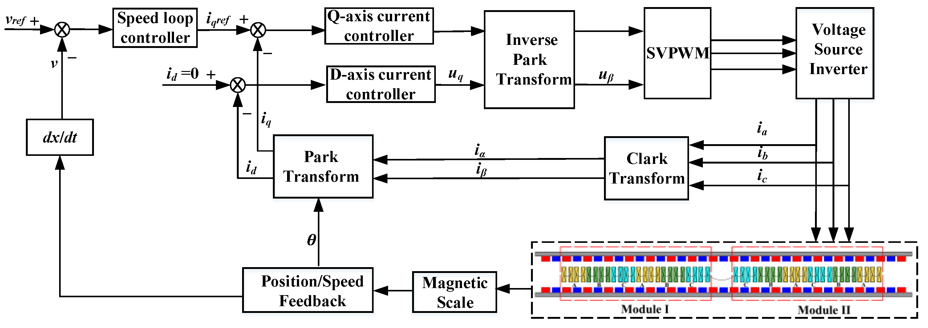
4. Vector Control Strategy for the Two-Module PMLSM

Since the windings of the two-module connect in series, each module has the same currents. Furthermore, the two-module has the same structural parameters. The position of the two-module is measured by the magnetic scale; thus, the position and speed of the two-module could be feedback to the control loop. The merits of this vector control system are that only one position sensor and one speed loop controller are required, as shown in Figure 3.
Accurate mathematical models are meaningful in the initial design of a two-module motor and driving control. It can be found that the above equations of the two-module motor in Section 3 contain coupling inductance terms. Meanwhile, the equations of the flux linkage, voltage, and thrust are related to the primary position. In order to apply in the actual control strategy, these mathematical models in the three-phase abc stationary coordinate should be transformed into a dq axis rotating coordinate.
The physical quantities in the dq coordinate can be obtained by the physical quantities in the abc coordinate. Based on the principle that the magnitudes of the physical quantities remain unchanged in the coordinate transformation, the constant amplitude Park transformation equation is as follows:
P = 2 3 [ cos ( v t τ m 2 π ) cos ( v t τ m 2 π 2 3 π ) cos ( v t τ m 2 π + 2 3 π ) sin ( v t τ m 2 π ) sin ( v t τ m 2 π 2 3 π ) sin ( v t τ m 2 π + 2 3 π ) 1 2 1 2 1 2 ]
Then, the dq axis current matrix idq0 = PI. Similarly, the dq axis inductance matrix is Ldq0 = PLP−1.
For symmetric systems, it is generally not necessary to consider the 0-axis component. Without considering the cross-coupling inductance between the dq axis, the armature flux linkage in the dq coordinate can be expressed as
ψ d = i = 1 2 ( L d i + M d 1 d 2 )
ψ q = i = 1 2 ( L q i + M q 1 q 2 )
where ψd is the d-axis flux linkage, ψq is the q-axis flux linkage, Md1d2 and Mq1q2 are the mutual inductance of Module I and Module II in the dq axis, Ldi and Lqi are the self-inductance of Module I and Module II in the dq axis.
On substituting (16) and (17) into the dq voltage function, the expression can be written into
u d = i = 1 2 R d i i d + i = 1 2 ( L d i + M d 1 d 2 ) d i d d t π v τ m i = 1 2 ( L q i + M q 1 q 2 ) i q
u q = i = 1 2 R q i i q + i = 1 2 ( L q i + M q 1 q 2 ) d i q d t + π v τ m [ i = 1 2 ( L d i + M d 1 d 2 ) i d + ψ P M ]
where ud is the d-axis voltage, uq is the q-axis voltage, id the d-axis current, iq the q-axis current, Rdi is the d-axis equivalent resistance, Rqi is the q-axis equivalent resistance.
Given that the d-axis current id = 0, the average thrust force of the whole motor can be expressed as:
F = 3 π 2 τ p ψ P M i q

5. Experimental Verification and Results

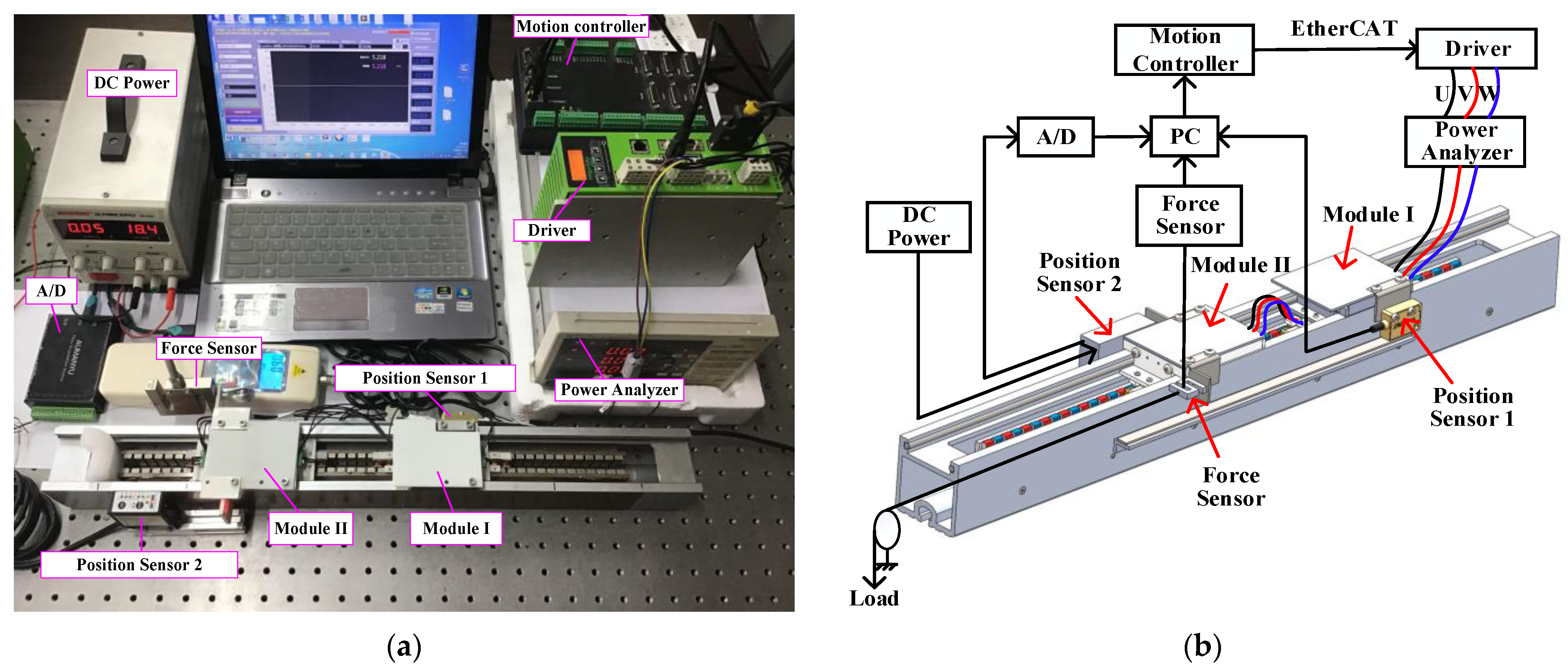
5.1. Experimental Setup

In order to verify the synchronous motion characteristics between the two-module and the proposed mathematical model, a prototype of the PMLSM has been manufactured. For this prototype, the primary component consists of the two-module, and the windings of adjacent units are connected in series. The experiment platform includes the prototype and its driver, EtherCAT motion controller, the force sensor, the power analyzer, and the position sensor, as shown in Figure 4. A linear magnetic scale sensor (position sensor 1) is fixed on the side of Module I, which is used as a position sensor. A laser position sensor (position sensor 2) measures the position of Module II, of which the measuring range is 0 to 10 mm. The measuring accuracy of both sensors is 1 μm. A tension-compression sensor (force sensor) is used to record the average thrust of the two-module through the load linked with this sensor. Then, the thrust data are collected in the case of a various current. The magnetic scale (SPM MR200A) can record the position of the two-module in real time. The motion controller (ZMC432) can receive the position signal of the two-module. Then, the motion controller sends the control signal to the driver (HIWIN D1). Therefore, the thrust force produced by the two-module can be controlled.

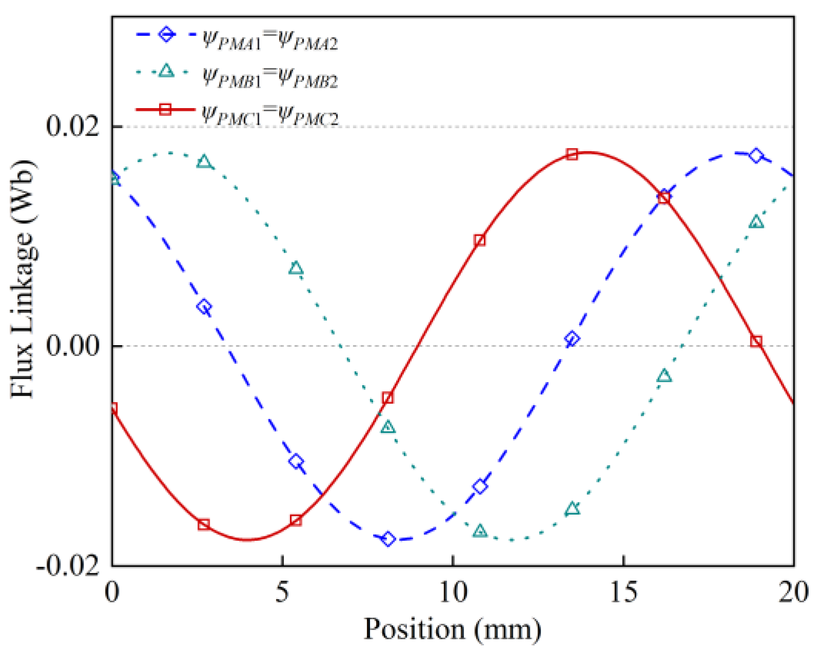
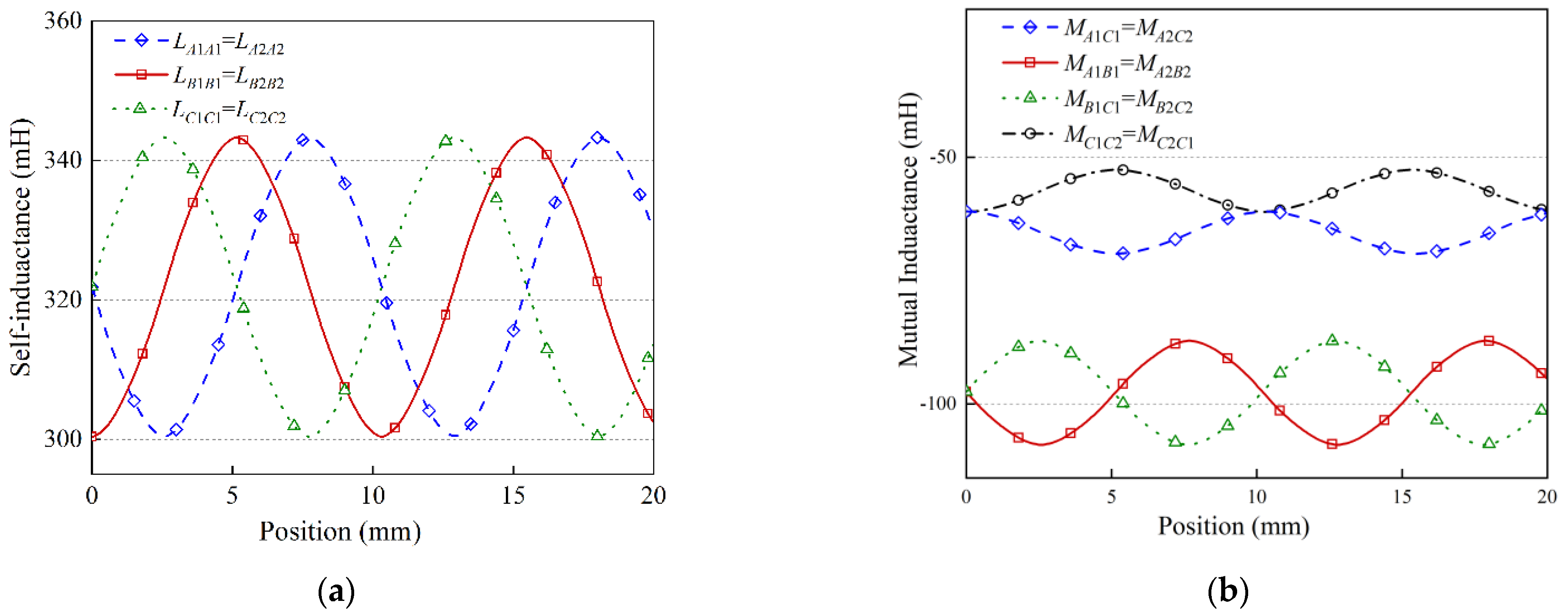
5.2. FEM Results of the PM Flux Linkage and Inductance

As seen, the above-derived mathematical models are nonlinear coupling equations. Some parameters of the analytical model are determined by FEM for the air-core linear motor to obtain accurate and fast results [27]. Hence, to obtain accurate computational results, we replaced the complicated analytical models of PM flux linkage and inductance with FEM. This is called the finite element–analytical method (FEAM). Based on the design parameters of the two-module motor, Module I and Module II in this paper possess the same electrical parameters. In addition, due to the reversibility of mutual inductance, Mkj = Mjk.
Figure 5 shows that the amplitude of the three-phase flux linkage is almost the same, and the initial angle of each phase differs by 120°. Furthermore, the waveforms of the three-phase flux linkage fluctuate from –0.018 to 0.018 Wb. Figure 6 shows that the waveforms of self-inductance and mutual inductance of each module are approximately sinusoidal. The waveforms of inductance for this motor vary with position. For self-inductance, LA1A1, LB1B1, and LC1C1 are almost equal. For mutual inductance, MA1B1 and MB1C1 are larger than MA1C1. For external mutual inductance between Module I and Module II, MC1C2 is nearly the same as MA1C1, whereas MA1A2 and MB1B2 are near zero. This is mainly due to the winding arrangements of the whole motor and the distance between each phase. Figure 6a shows that the three-phase self-inductance of each module fluctuates from 300.4 to 343.3 μH. Figure 6b shows the mutual inductance composed of MA1B1 and MB1C1 fluctuates from −87.1 to −108.2 μH, whereas MA1C1 fluctuates from −60.9 to −69.5 μH. Meanwhile, the mutual inductance between Module I and Module II composed of MC1C2 fluctuates from –61.1 to −52.5 μH. We can see from Figure 6 that the phase difference between any two phase inductances are almost equal. Furthermore, the inductance changes slightly with the current due to the large air gap.

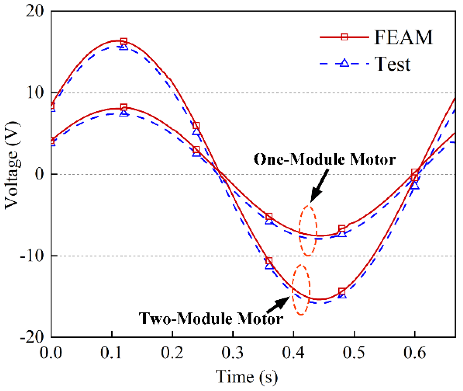
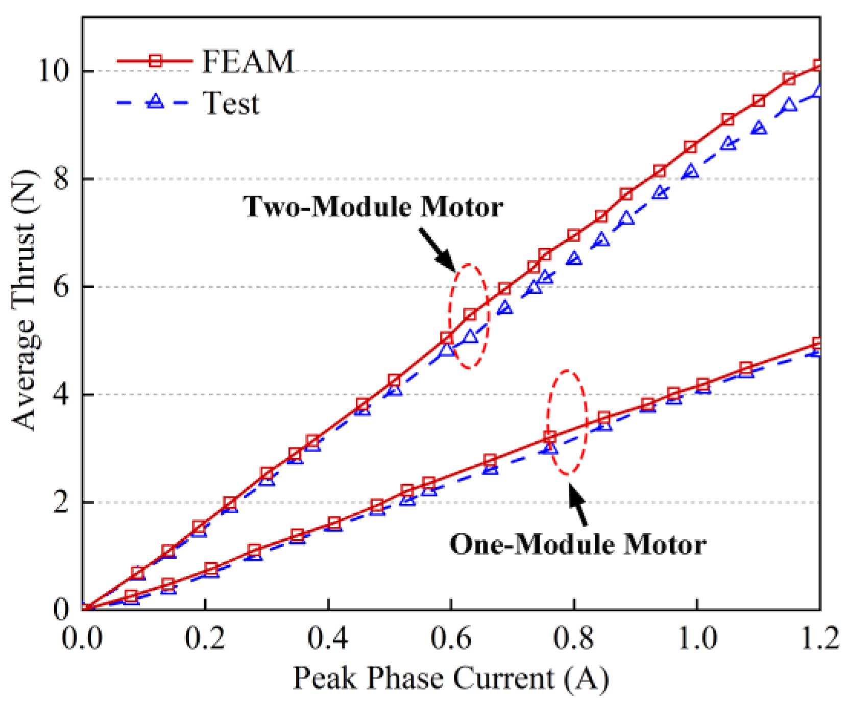
5.3. Voltage and Thrust Characteristics

In this section, the comparisons between the one-module and two-module are conducted by adopting id = 0 vector control strategy. When the peak phase current is 1.2 A, Figure 7 compares the one-phase voltage of the one-module motor and two-module motor, which shows that the voltage amplitude of the one-module motor and two-module motor is 8.04 and 16.39 V, respectively. Therefore, the voltage amplitude of the two-module motor is 1.9% larger than that of two times the one-module motor. This is mainly due to the mutual inductance between Module I and Module II. Furthermore, the FEAM results match well with the test results. The load cell with the full range of 20 N and the measuring accuracy of 0.2% is employed in this platform. Compared with the one-module motor linked with load, the two-module motor is used as a whole to drag the load. Figure 8 presents the average thrust of the one-module motor and two-module motor, varying with peak phase current. Due to the large air gap between the primary and the secondary, the PMLSM cannot have magnetic saturation. Therefore, the average thrust is basically linear with the increase in peak phase current. The minor differences between FEAM prediction and measured results may come from the ideal mathematical conditions, manufacturing error, and measuring accuracy. The average thrust of the two-module motor is 2.7% larger than that of two times the one-module motor.

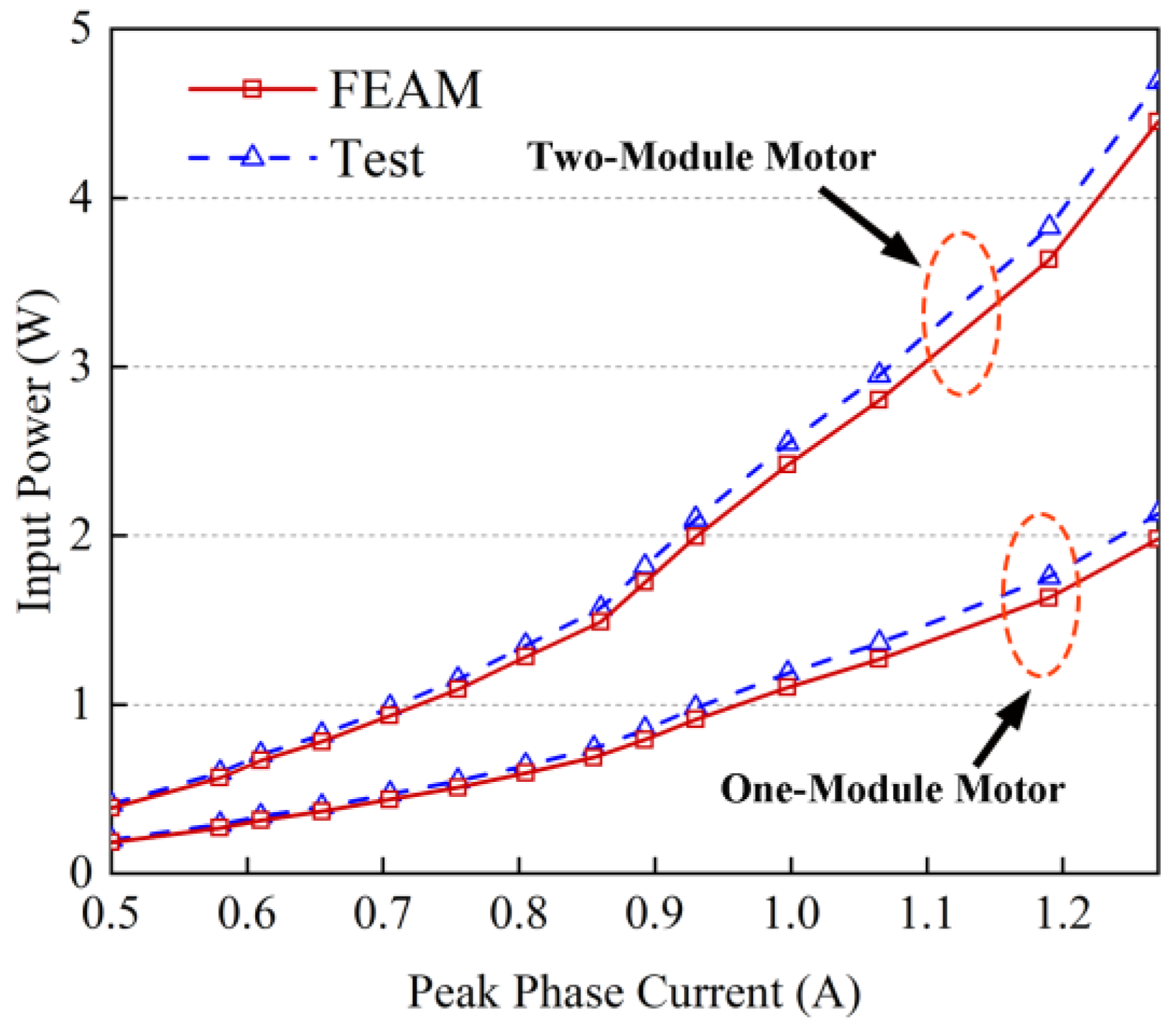
5.4. Input Power Characteristic

Figure 9 shows the input powers of the one-module motor and two-module motor varying in peak phase current. The two-module input power increases from 0.41 to 4.66 W. The one-module input power increases from 0.20 to 2.23 W. Thus, the average input power of the two-module motor is 4.5% larger than that of two times the one-module motor. Furthermore, with the rise in peak phase current, the input power increases dramatically in the current range from 1.1 to 1.3 A. This is mainly because of the increasing ratio of copper loss. The measured results are slightly larger than the FEAM results due to the actual existing harmonic current.

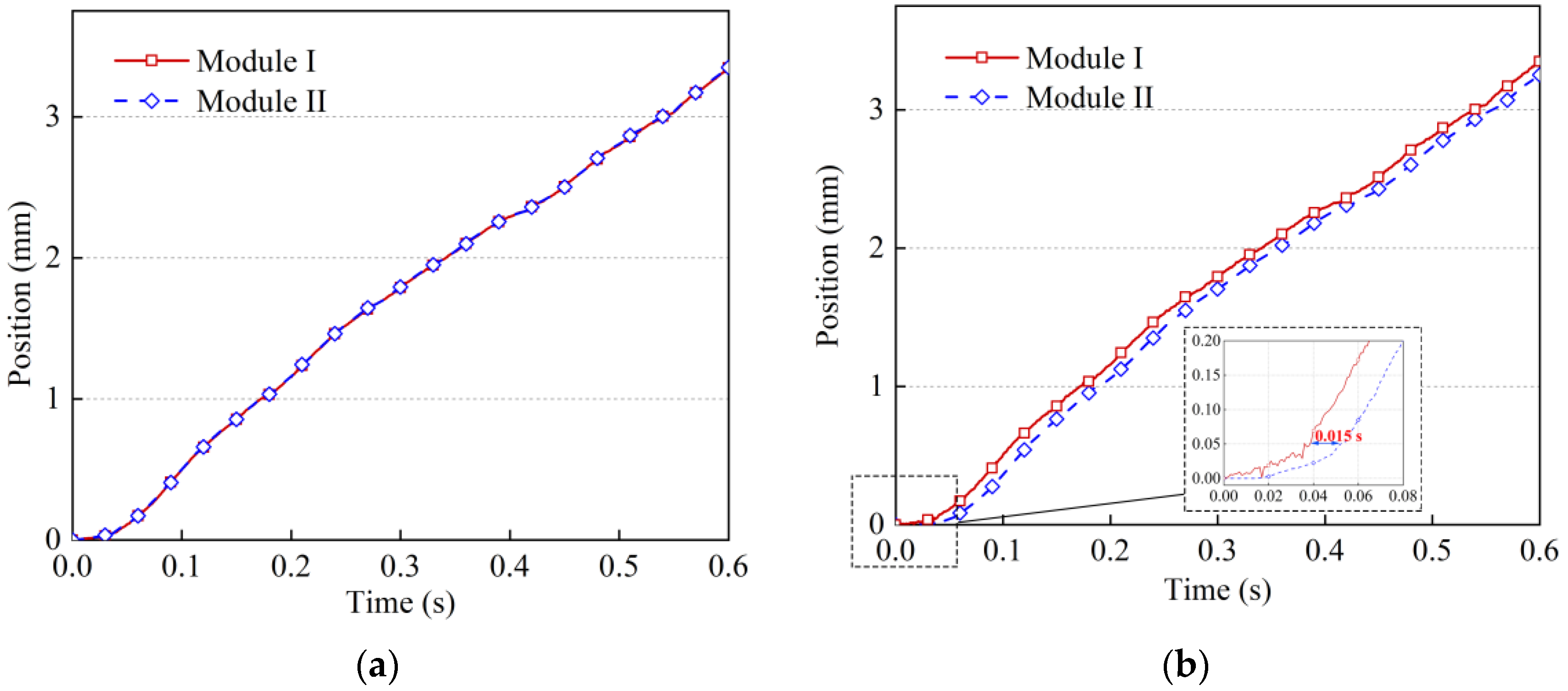
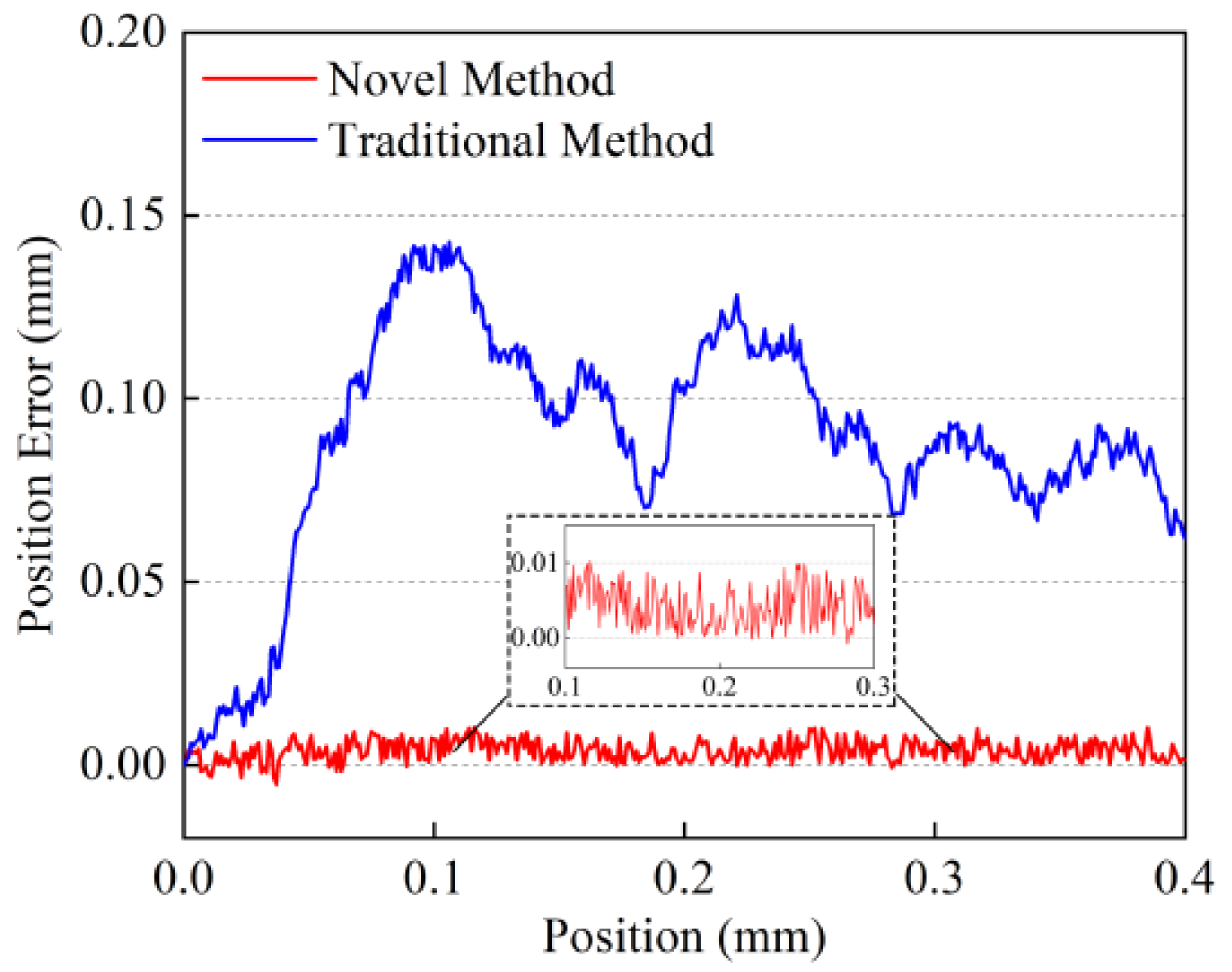
5.5. Synchronization Performance Comparison without External Disturbance

In this paper, there are two power supply modes for the two-module that are used to compare synchronization performance. The novel mode is that the windings of Module I and Module II connect in series. Then, the two-module is driven by one driver. Both ways use the id = 0 vector control strategy. The traditional mode is that Module I and Module II are driven by two drivers. The two drivers communicate in series through the EtherCAT bus.
Figure 10a shows the position of Module I and Module II without external disturbance by experiment. As seen, the position of Module I matches well with Module II obtained by this new approach. For comparison, Figure 10b displays the position synchronization between the two modules by the conventional approach. Due to the communication delay, the position of Module II lags behind Module I about 0.015 s during the starting stage. This leads to the asynchronous position between the two modules. Furthermore, to quantitatively analyze the synchronous performance of Module I and Module II in the initial stage, waveforms of synchronization error are presented in Figure 11. The maximum position errors of the novel method are less than 10 μm. This minor discrepancy between Module I and Module II may attribute to the friction force caused by the manufacturing errors of the two-module. However, the maximum position errors of the traditional method are about 150 μm. The maximum errors between the two approaches differ nearly 15 times.

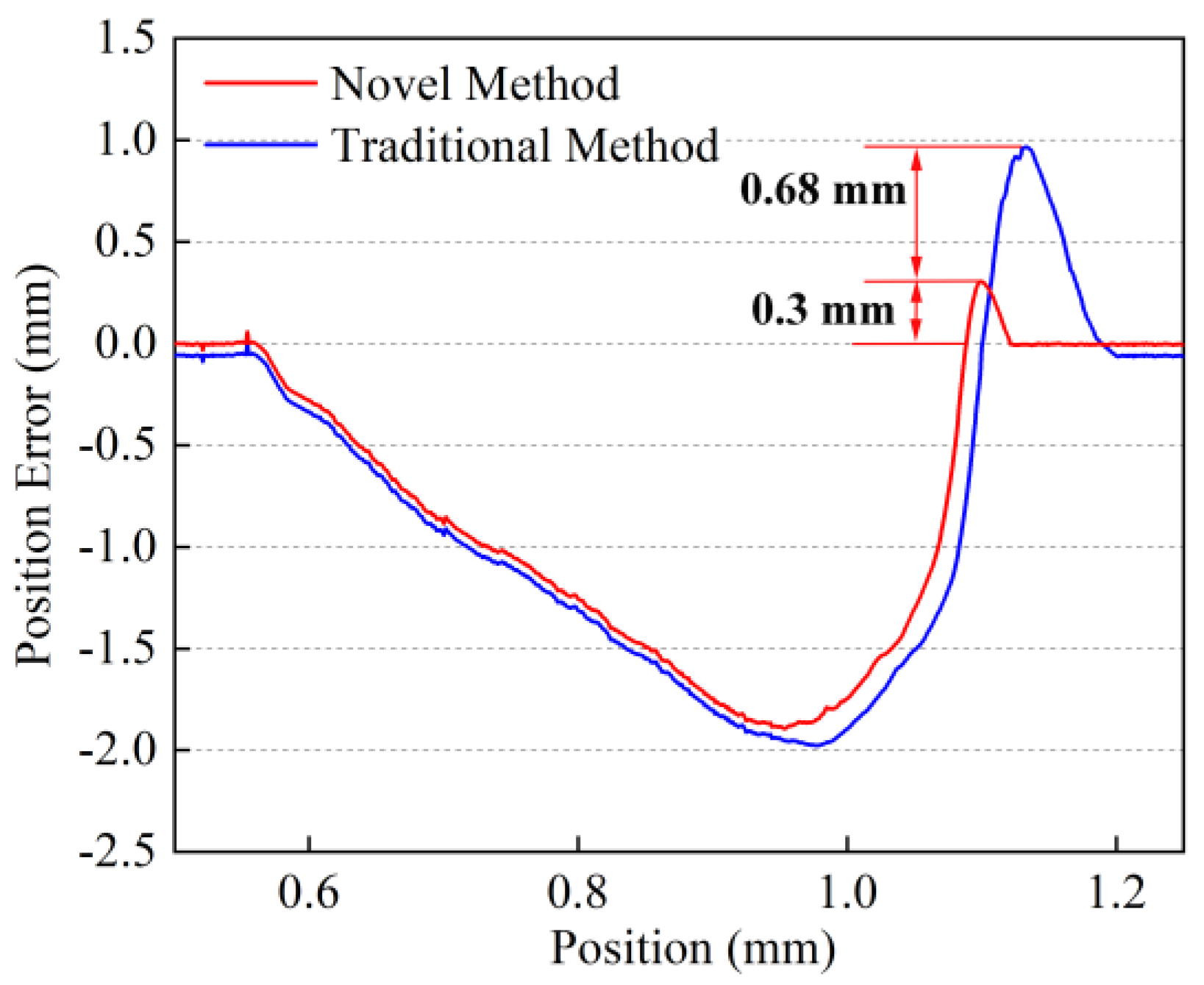
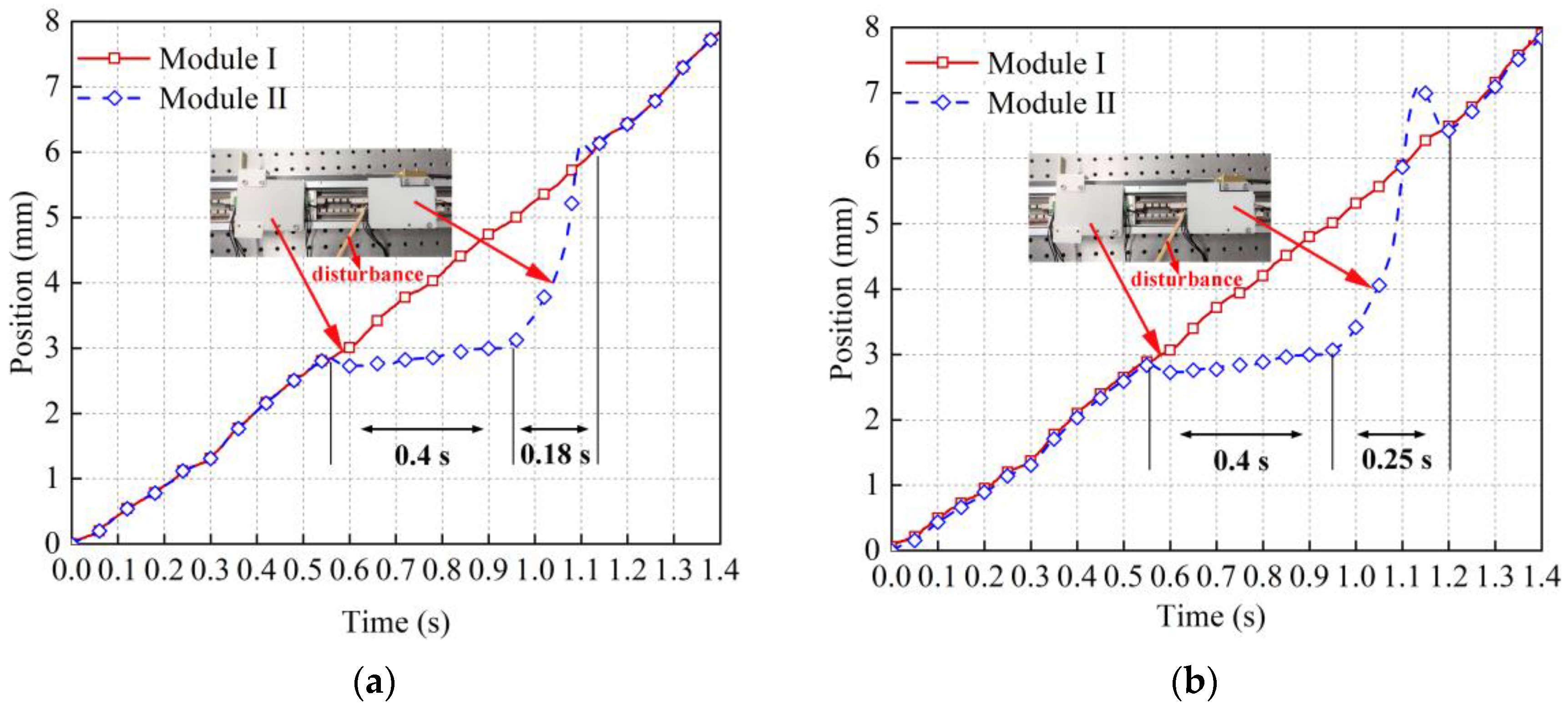
5.6. Synchronization Performance Comparison with External Disturbance

Depending on the permanent magnetic periodic distribution principle, we performed the disturbance experiment within the distance of τ, namely 10 mm. Otherwise, the disturbed Module cannot return to its synchronous position and falls behind the integral multiple of pole pitch due to the interaction of a traveling magnetic field and PMs. To analyze the synchronous performance of the two-module in the case of disturbance, Module II is exerted on a lasting 0.4 s external load as shown in Figure 12a. Depending on the motion Equation (16), the speed of each module is influenced by the disturbance force. When the external load is applied to Module II, the speed of Module II drops rapidly. When the load is released, Module II can attain the synchronous position within an adjusting time of 0.18 s. Using the same experimental process, Module II can attain the synchronous position within an adjusting time of 0.25 s, as shown in Figure 12b. Compared with the traditional method, the dynamic response of the new approach can reduce 22.2% of adjusting time. Meanwhile, Figure 13 shows that the maximum control overshoot of the novel and traditional ways is about 0.3 and 0.98 mm, respectively. The maximum overshoot decreases by 60% through the new method.

6. Conclusions

This article proposes a new approach with a two-module series power supply topology to overcome the disadvantages of the independent synchronous method. The mathematical models of the proposed topology structure, including the voltage, average thrust, and input power, have been analyzed. The experimental results agree well with these mathematical models. Moreover, comparisons of the conventional and novel methods are conducted under the no-external and external disturbance conditions, respectively. From the above comparisons, the following conclusions can be drawn:
(1)
The proposed novel method can realize no control delay time between the two modules, thus improving the two-module synchronization performance. Furthermore, the proposed novel method has better dynamic response in the sudden change of external disturbance.
(2)
Influenced by the coupling inductance between the two modules, the two-module motor’s peak voltage, average thrust, and input power are 1.9%, 2.7%, and 4.5% larger than those of two times the one-module motor, respectively. Furthermore, accurate mathematical models are significant to the design and control of the two-module PMLSM.
Therefore, this method can be applied to multi-module synchronous motions by adding the voltage and power of the driver.

Author Contributions

H.Y. determined the theme and structure of the article, provided professional knowledge in the field of multi-motor synchronous motion control, and modified this article. F.Z. wrote the entire content of this article. H.Z. participated in the experimental process. All authors have read and agreed to the published version of the manuscript.

Funding

This research received Enterprise Funding (grant no. 102-611902601).

Institutional Review Board Statement

Not applicable.

Informed Consent Statement

Not applicable.

Data Availability Statement

Not applicable.

Conflicts of Interest

The authors declare no conflict of interest.

References

  1. Li, C.; Li, C.; Chen, Z.; Yao, B. Advanced synchronization control of a dual-linear-motor-driven gantry with rotational dynamics. IEEE Trans. Ind. Electron. 2018, 65, 7526–7535. [Google Scholar] [CrossRef]
  2. Wang, B.; Iwasaki, M.; Yu, J. Command filtered adaptive backstepping control for dual-motor servo systems with torque disturbance and uncertainties. IEEE Trans. Ind. Electron. 2022, 69, 1773–1781. [Google Scholar] [CrossRef]
  3. Li, J.; Wang, Y.; Li, Y.; Luo, W. Reference trajectory modification based on spatial iterative learning for contour control of two-axis NC systems. IEEE/ASME Trans. Mechatron. 2020, 25, 1266–1275. [Google Scholar] [CrossRef] [Green Version]
  4. Ghaffari, A.; Ulsoy, A.G. Dynamic contour error estimation and feedback modification for high-precision contouring. IEEE/ASME Trans. Mechatron. 2016, 21, 1266–1275. [Google Scholar] [CrossRef]
  5. Wang, Y.-W.; Zhang, W.-A.; Yu, L. A Linear Active Disturbance Rejection Control Approach to Position Synchronization Control for Networked Interconnected Motion System. IEEE Trans. Control Netw. Syst. 2020, 7, 1746–1756. [Google Scholar] [CrossRef]
  6. Kuang, Z.; Gao, H.; Tomizuka, M. Precise linear-motor synchronization control via cross-coupled second-order discrete-time fractional-order sliding mode. IEEE/ASME Trans. Mechatron. 2021, 26, 358–368. [Google Scholar] [CrossRef]
  7. Barton, K.L.; Alleyne, A.G. A cross-coupled iterative learning control design for precision motion control. IEEE Trans. Control Syst. Technol. 2008, 16, 1218–1231. [Google Scholar] [CrossRef]
  8. Zhang, P.; Zhang, J.H.; He, D.S.; Zhang, B. Based on Adjacent Cross-Coupling of Multi-Motor Synchronous Drive. Adv. Mater. Res. 2011, 201–203, 1093–1097. [Google Scholar] [CrossRef]
  9. Li, J.; Fang, Y.; Huang, X.; Li, J. Comparison of synchronization control techniques for traction motors of high-speed trains. In Proceedings of the 2014 17th International Conference on Electrical Machines and Systems (ICEMS), Hangzhou, China, 22–25 October 2014; pp. 2114–2119. [Google Scholar]
  10. Shi, T.; Liu, H.; Geng, Q.; Xia, C. Improved relative coupling control structure for multi-motor speed synchronous driving system. IET Electr. Power Appl. 2016, 10, 451–457. [Google Scholar] [CrossRef]
  11. Zeng, Z.; Shen, Y.; Lu, Q.; Wu, B.; Gerada, D.; Gerada, C. Investigation of a Partitioned-Primary Hybrid-Excited Flux-Switching Linear Machine with Dual-PM. IEEE Trans. Ind. Appl. 2019, 55, 3649–3659. [Google Scholar] [CrossRef]
  12. Li, J.; Huang, X.; Zhou, B.; Yu, H.; Huang, Q. Design principle of a 16-pole 18-slot two-sectional modular permanent magnet linear synchronous motor with optimisation of its end tooth. IET Electr. Power Appl. 2020, 14, 441–447. [Google Scholar] [CrossRef]
  13. Shi, T.; Zhang, X.; Zhou, Z.; Xia, C. Precise Contour Control of Biaxial Motion System Based on MPC. IEEE J. Emerg. Sel. Top. Power Electron. 2018, 6, 1711–1721. [Google Scholar] [CrossRef]
  14. Xiong, H.; Zhang, M.; Zhang, R.; Zhu, X.; Yang, L.; Guo, X.; Cai, B. A new synchronous control method for dual motor electric vehicle based on cognitive-inspired and intelligent interaction. Future Gener. Comput. Syst. 2018, 94, 536–548. [Google Scholar] [CrossRef]
  15. Wu, Y.; Cheng, Y.; Wang, Y. Research on a Multi-Motor Coordinated Control Strategy Based on Fuzzy Ring Network Control. IEEE Access 2020, 8, 39375–39388. [Google Scholar] [CrossRef]
  16. Bian, C.; Hua, M.; Zheng, D. Cross-coupling synchronous control of dual-motor networked motion control system. In Proceedings of the Chinese Control Conference (CCC), Dalian, China, 26–28 July 2017; pp. 7628–7633. [Google Scholar] [CrossRef]
  17. Zhong, G.; Shao, Z.; Deng, H.; Ren, J. Precise Position Synchronous Control for Multi-Axis Servo Systems. IEEE Trans. Ind. Electron. 2017, 64, 3707–3717. [Google Scholar] [CrossRef]
  18. Shen, H.; Li, P.; Luo, X. Synchronous multi-axis motion control based on modified EtherCAT distributed clock. In Proceedings of the 2020 Chinese Automation Congress (CAC), Shanghai, China, 6–8 November 2020; pp. 3674–3678. [Google Scholar] [CrossRef]
  19. Li, G.-J.; Ren, B.; Zhu, Z.Q.; Foster, M.P.; Stone, D.A. Demagnetization Withstand Capability Enhancement of Surface Mounted PM Machines Using Stator Modularity. IEEE Trans. Ind. Appl. 2017, 54, 1302–1311. [Google Scholar] [CrossRef] [Green Version]
  20. Tan, Q.; Huang, X.Z.; Li, L.; Wang, M. Magnetic Field Analysis and Flux Barrier Design for Modular Permanent Magnet Linear Synchronous Motor. IEEE Trans. Ind. Electron. 2019, 67, 3891–3900. [Google Scholar] [CrossRef]
  21. Zheng, M.; Zhu, Z.Q.; Cai, S.; Xue, S.S. A Novel Modular Stator Hybrid-Excited Doubly Salient Synchronous Machine With Stator Slot Permanent Magnets. IEEE Trans. Magn. 2019, 55, 8104409. [Google Scholar] [CrossRef] [Green Version]
  22. Ma, M.; Li, L.; Zhang, J.; Yu, J.; Zhang, H.; Mingna, M. Investigation of Cross-Coupling Inductances for Long-stator PM Linear Motor Arranged in Multiple Segments. IEEE Trans. Magn. 2015, 51, 8205304. [Google Scholar] [CrossRef]
  23. Bang, D.-J.; Hwang, S.-H. Wide Air-gap Control for Multi-module Permanent Magnet Linear Synchronous Motors without Magnetic Levitation Windings. J. Power Electron. 2016, 16, 1773–1780. [Google Scholar] [CrossRef] [Green Version]
  24. Zhou, Y.; Huang, K.; Sun, P.; Dong, R. Analytical Calculation of Performance of Line-Start Permanent-Magnet Synchronous Motors Based on Multidamping-Circuit Model. IEEE Trans. Power Electron. 2020, 36, 4410–4419. [Google Scholar] [CrossRef]
  25. Liu, J.; Bai, J.; Zheng, P.; Zhang, S.; Wang, M.; Yin, Z. Torque analysis of magnetic-field-modulated double-rotor machines with virtual work method. In Proceedings of the International Conference on Electrical Machines and Systems (ICEMS), Harbin, China, 11–14 August 2018; pp. 1885–1889. [Google Scholar]
  26. Neyman, V.Y.; Markov, A.V. Model of electromechanical energy converter with variable inductance. In Proceedings of the 2019 20th International Conference of Young Specialists on Micro/Nanotechnologies and Electron Devices (EDM), Erlagol, Russia, 29 June–3 July 2019; pp. 765–769. [Google Scholar]
  27. Kazan, E.; Onat, A. Modeling of Air Core Permanent-Magnet Linear Motors with a Simplified Nonlinear Magnetic Analysis. IEEE Trans. Magn. 2011, 47, 1753–1762. [Google Scholar] [CrossRef]
Figure 1. Three-dimensional view of the two-module PMLSM.
Energies 15 03617 g001
Figure 2. Configuration of the proposed two-module PMLSM. (a) The 24s/28p structure diagram. (b) Winding connections of the 24s/28p structure.
Energies 15 03617 g002
Figure 3. Control diagrams of the two-module PMLSM.
Energies 15 03617 g003
Figure 4. (a) Test platform of the two-module PMLSM. (b) Schematic diagram of the test platform.
Energies 15 03617 g004
Figure 5. FEM results of the three-phase PM flux linkage of each module varying with position.
Energies 15 03617 g005
Figure 6. FEM results of the three-phase inductance. (a) The self-inductance of each module. (b) The interior and external mutual inductance of each module.
Energies 15 03617 g006
Figure 7. One phase voltage comparison of the one-module motor and two-module motor by FEAM and test.
Energies 15 03617 g007
Figure 8. Average thrust comparison of the one-module motor and two-module motor varying with peak phase current.
Energies 15 03617 g008
Figure 9. Input power comparison of the one-module motor and two-module motor varying with peak phase current.
Energies 15 03617 g009
Figure 10. Position of the two-module versus time under the no external disturbance condition. (a) The novel method. (b) The conventional method.
Energies 15 03617 g010
Figure 11. Position errors of the two methods between the two modules without external disturbance.
Energies 15 03617 g011
Figure 12. Position of Module I and Module II versus time under the external disturbance condition. (a) The novel method. (b) The traditional method.
Energies 15 03617 g012
Figure 13. Position errors of the two methods between the two-module under the external disturbance condition.
Energies 15 03617 g013
Table 1. The main parameters of the 24s/28p PMLSM.
SymbolQuantityValue
pPole pairs14
τPole pitch8 mm
QVirtual slots24
hfHeight of secondary iron5 mm
τmWidth of PM10 mm
hmHeight of PM5 mm
hcHeight of coil5.4 mm
wsWidth of coil 3.75 mm
gLength of the sided air-gap1 mm
LLongitudinal length55 mm
NNumber of turns per coil105
RPhase resistance7.6 Ω
l1Length of Module I79 mm
l2Length of Module II79 mm
Publisher’s Note: MDPI stays neutral with regard to jurisdictional claims in published maps and institutional affiliations.

