1. Introduction
Multilevel Inverters (MLIs) are state-of-the-art power electronic converters that have taken the place of traditional inverters in many applications, such as renewable energy systems, grid integration systems, mechanical drives, electric vehicles, and FACTS [
1,
2,
3,
4]. MLIs are mostly preferred in different applications because of their efficient power generating features with lower switching losses and low voltage stress across switches [
5]. MLIs are mainly classified as Neutral Point Clamped (NPC), Flying Capacitor (FC), and Cascaded H-bridge Inverter [
6,
7,
8,
9]. The first two (NPC and FC) suffer from voltage imbalance, and their component counts that dramatically increase with an increasing number of voltage levels. Cascaded H-bridge Inverters can generate significant voltage levels with fewer switches, but each unit of the H-bridge requires an isolated dc source. To mitigate the limitations of classical MLIs, several switched capacitor MLIs have been explored, which have the essential characteristics of inherent voltage balance, voltage boosting feature with the least number of input DC power supplies, and switching components.
The performance of the converter depends largely on the selection of modulation method. The effective modulation strategy reduces the harmonics of output voltage and current to a level acceptable under IEEE 519 standards. SHE is a low frequency-based modulation strategy in which non-transcendental multivariable equations are solved to find the angles corresponding to desired harmonic elimination. A low switching frequency modulation scheme has less switching loss than a high-frequency modulation scheme. Moreover, a dead time delay requirement to avoid the shoot-through problem is also not present in the low switching frequency modulation scheme. Thus, the generation of gate signals is quite simple. SHE has the advantage of the complete elimination of desired lower-order harmonics. Although the overall THD usually is higher for most of the modulation index range than Nearest Level Control (another popular low-modulation control strategy), the advantage of desired harmonic elimination in SHE makes it suitable for many applications. However, since the SHE equations are non-linear, they are not easy to solve to identify a possible set of values at a particular modulation index [
10]. Several iterative numerical techniques were used to solve the SHE equation that give a definite set of angles with the requirement of proper initial prediction of modulation index [
11,
12]. Many algorithms have been used to solve the non-linear SHE equations and obtain the switching patterns of the inverter. The most popular algorithms are the Newton-Raphson (NR) algorithm, Particle Swarm Optimization (PSO) and Genetic Algorithm (GA) [
13]. Although the NR method is very simple and efficient for solving smaller equations, its rapid convergence depends completely on the initial selection of switching angles. PSO is a global optimization technique and has rapid convergence, which often leads to unwanted premature convergence [
14]. GA is based on the theory of “survival of the fittest” given by Darwin, in which only the fittest individuals will survive and reproduce, and is among the earlier methods to solve the selective harmonic elimination problem. Many variants have also been suggested in the literature, but the GA-based method may not give the optimum global value for all modulation indexes [
15,
16]. The GA-based optimization technique is used to compute switching angles for implementing the SHE modulation technique in a seven-level inverter [
17].
Nevertheless, GA implementation is quite challenging, as it requires the appropriate selection of various parameters such as population size and mutation rate [
18]. Both PSO and GA come under metaheuristic techniques, which are nature-inspired techniques that give close solutions. These techniques are computationally efficient, as they do not explore every possible solution before converging to final values. Metaheuristic techniques are mainly classified into the following categories: (i) deterministic methods, in which a definite trajectory is followed from initial random values to the final solution, and stochastic methods, which permit a probabilistic jump from present value to the next; (ii) memory-based techniques, which keep track of the historical data and utilize it for future data determination, or memory-less techniques; (iii) one of various neighborhood methods, in which some meta-heuristics allow a limited set of moves from the current solution (however, many meta-heuristics employ operators and parameters to allow multiple neighborhoods); (iv) static techniques, which use only previously defined operators to control the search, or dynamic methods that update the objective function with the requirement of the current search values; and finally (v) greedy techniques, which usually look in the vicinity of the current search and immediately updates to a better solution when it is found. However, non-greedy techniques require some iterations before updating into new solutions [
19].
In this paper, we use the SHE pulse width modulation (PWM) technique to attain the desired fundamental output voltage and eliminate undesirable lower harmonic components in the output waveform using the Symbiotic Organism search algorithm. A novel nine-level three-phase switched capacitor topology has also been proposed. The symbiotic organism search (SOS) search process is based on previously defined parameters, and after each comparison value is updated to obtain a better result, this method falls in the category of static and greedy techniques, which will help determine objective-oriented results.
The SHE modulation technique is preferred for low-frequency applications, as it enables the inverter to control fundamental voltage and remove lower-order harmonics [
18]. The lower order harmonics are more dominant and troublesome, as they lead to unnecessary heating of the devices connected at the load side [
20,
21,
22]. The SOS technique is utilized to solve the non-linear equations of SHE and for the nine-level MLI. The main features of the work are as follows:
A single dc source is required in the nine-level topology to generate a nine-level three-phase output voltage.
In this topology, a small number of devices (switches, capacitors, and diodes) can increase the output voltage. The voltage stress across the components is also restricted to the source voltage.
A nature-inspired meta-heuristic approach called the symbiotic optimum search (SOS) was used to find the optimum angles.
SHE PWM technique was employed for controlling the output voltage.
This paper is organized as follows.
Section 2 describes the basic circuit configuration of the nine-level SCMLI and its operation.
Section 3 describes the SHE PWM technique to control the operation of the inverter. In
Section 4, the SOS algorithm and its main stages are briefly explained. Power loss analysis is explained in
Section 5. Analysis and consideration of simulation and test results are shown in
Section 6.
Section 7 concludes.
2. Circuit Configuration of the Proposed SCMLI
Figure 1 illustrates the single-phase version of the proposed nine-level switched capacitor MLI (SCMLI). The proposed topology has the features of boosted voltage and self-balanced capacitor voltage.
Table 1 shows the switch states for generating different voltage levels.
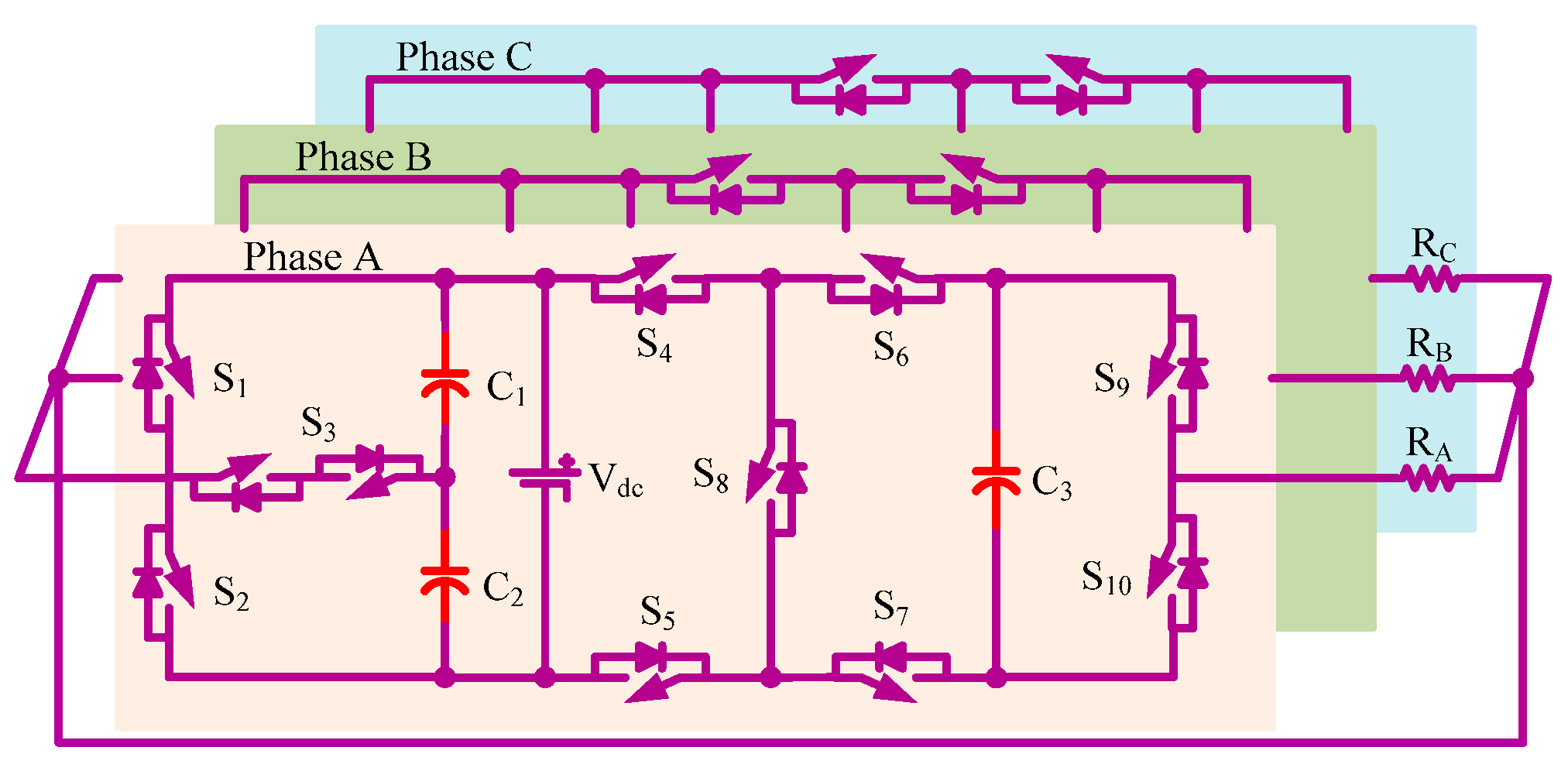
Figure 2 illustrates the circuit diagram of a three-phase nine-level MLI. Each phase consists of three capacitors (C
1, C
2, and C
3), ten switches (S
1 to S
10), and a single input voltage source. This topology has the advantage of low voltage stress across the switches and capacitors, limited to V
dc.
Figure 3 represents all possible voltage levels (0, ±0.5V
dc, ±V
dc, ±1.5V
dc, and ±2V
dc) generated by the SCMLI.
3. The Selective Harmonic Elimination Technique (SHE)
SHE PWM is a technique that can be used to control the harmonics in a power electronic converter and its application, especially the MLI (input or output) waveform.
Switching losses are generally high in high-power converters, significantly reducing the converter’s efficiency. Reducing these losses is a subject of importance [
23]. Compared with other PWM techniques, the SHE PWM operates at a fundamental or close to fundamental frequency. It results in reducing the switching power losses and better harmonic performance. This feature adds it to an advantageous solution for many applications, such as grid-connected converters and medium-voltage drive applications.
Motor drive converters: SHE PWM is used to eliminate low order voltage harmonics, reducing both the acoustic noise and common-mode voltage.
Active rectifiers: SHE PWM can be used to minimize the line current THD and balance each cell’s voltage and power levels.
Grid-connected converters: SHE PWM can be applied to grid-connected converters to minimize harmonics, reduce switching losses, and reduce filtering requirements, along with other benefits, such as interfacing photovoltaic systems with the grid.
The formulation of SHE PWM includes variable levels, unequal, non-symmetrical, half-wave symmetry and quarter-wave symmetry. The quarter-wave symmetry is simplest because sine coefficient of odd harmonics, the dc component and even harmonics are all equivalent to zero, making calculation easier and requiring the least number of equations for a solution due to a high degree of symmetry in the waveform. N variables are required for switching angles with constraints 0 <
δ1 <
δ 2 <
δ3 … <
δN <
π/2. In half-wave symmetric formulation, 2 N transitions are considered in the half period. Both cosine and sine terms of odd harmonics need to be controlled in this method. In non-symmetric formulation, 4 N + 2 transitions need to be formulated in the entire period. This is the least attractive of all the formulations [
24,
25,
26].
The objective function
‘O’ that needs to be minimized is given by Equation (1):
where
Vdc is the dc source voltage,
V1 represents the fundamental voltage,
Fi represents the Fourier equations for obtaining four angles, and the following equations give the constraints [
27,
28,
29,
30]:
The objective function defined by Equation (1) consists of two terms: one is to maintain the fundamental voltage, and the second is to minimize the harmonic components. These four Equations (2) to (4) are a set of transcendental equations, also called the SHE equations. There are four angles (δ1, δ2, δ3, and δ4); therefore, four things can be controlled. Formulation (2) is used to set the fundamental voltage to the desired value, whereas (3), (4), and (5) are formulated to eliminate the dominating 5th, 7th, and 11th order harmonic components by equating them to zero. These equations are solved by a metaheuristic technique to determine the optimum values of the unknown angles.
4. Symbiotic Organism Search (SOS) Algorithm
In this paper, a new and robust metaheuristic technique known as Symbiotic Organism Search (SOS) [
31,
32,
33] is used to determine the firing angles, which helps in mitigating and controlling the lower-order harmonics of the proposed inverter. This method is influenced by the natural phenomena of the ecosystem. Different organisms within the ecosystem depend on each other symbiotically to adapt to the changes and survive. A symbiotic relationship is mainly classified into three types:
Mutualism is an association between two organisms in which each benefit, e.g., the cooperation between coral reefs and algae.
Commensalism is an association between two organisms in which one organism benefits without harming another organism, e.g., tree frogs use plants as protection and shelter.
Parasitism is a relationship amid two organisms in which one is benefited though the other is harmed, e.g., mosquitoes feed on the blood of other organisms.
The symbiotic algorithm begins with generating a random population, in which the system has ‘n’ organisms (n: number of angles) in the ecosystem. Over the succeeding stages, the population is upgraded with each generation following the above-mentioned processes (mutualism stage, commensalism stage, and parasitism stage). Furthermore, an updated value in each step is accepted only if it has improved functional values compared to the previous one. This method of optimization continues till it satisfies the termination criteria [
28,
29].
Figure 4 shows the SOS algorithm in which the flow chart shows all important stages discussed above, including initialization, mutualism, commensalism, and parasitism.
The following steps reflect the above discussion.
Step 1: At modulation index M = 1, a random ecosystem is defined for i = i:n, initialization of maximum iteration MaxIter = 50, number of angles Npar = 4, and their limit are also defined with minimum value (0) and maximum value (π/2).
Step 2: In the mutualism phase, a mutual vector is defined with two different mutual organisms
X(
i) and
X(
j) to ascend their survival.
X(
j) is an arbitrary organism from the ecosystem chosen to interact with organism
X(
i). These organisms form a mutualistic relationship with the aim to increase their survival. A new candidate solution is calculated for
X(
i) and
X(
j) based on the mutualistic symbiosis amid organisms
X(
i) and
X(
j), given by Equation (6) and Equation (7), respectively:
A random number vector is rand(1, Npar). The mutualistic endeavor to boost their survival ability is reflected in the component of the Equations (6) and (7), (Xbest − Mutualvector). In this case, Xbest is essential, since it reflects the maximum level of adaptability. Equation (8) rpresents a mutual vector that depicts the connection between X(i) and X(j). This vector offers a unique feature, mainly when two creatures are far apart in the search space. This enables the exploration of new solutions. Furthermore, both interacting organisms are updated concurrently rather than being updated individually. Finally, if the organism’s new fitness is higher than the prior value, it will be updated.
Step 3: Similarly, from the ecosystem, a random creature
X(
j) is chosen to interact with
X(
i).
X(
i) will gain from
X(
j), but there will be no profit or harm to organism
X(
j) in this interaction. The new value of
X(
i) is obtained from
X(
i) and
X(
j) based on the commensalism relationship. The new value is accepted only if it is better than the previous interaction. The following equation gives the updated value of
X(
i):
where (
Xbest −
X(
j)) denotes the benefit or advantage supplied by
X(
j) in assisting
X(
i) in maximizing its survival in the environment. The best solution is used as the reference point in the SOS method, allowing it to utilize the optimistic regions near the best answer. This aids in the acceleration of convergence.
Step 4: A parasite vector is formed by duplicating organism X(i), and a arbitrarily chosen organism X(j) from the environment serves as the parasite vector’s host, provided that X(i) ≠ X(j). This parasite vector competes with other randomly chosen species, except its originator. The parasite vector replaces its host organism X(j) during this phase. Then, for both species fitness levels are assessed. If the parasite vector’s fitness value is higher, it will kill the host and take over the ecosystem’s position. If X(j) has a higher fitness value, it will be immune to the parasite, and the parasite will be unable to thrive in the environment.
The technique described above (steps 2–4) is continued until the maximum number of iterations has been achieved.
5. Power Loss Calculation
The semiconductor devices used in power converters include losses, mainly conduction losses, switching losses, gate driver losses, and off-state losses. Since the gate driver losses and off-state losses are negligibly small, they can be neglected. Hence, the conduction and switching losses are the major contributors for efficiency reduction. Unlike ideal switches, there are some losses in the practical switches categorized as static (conduction) losses and dynamic (switching) losses. When the switch is in a conducting state, there is certainly a voltage drop due to equivalent resistance of the switch, which results in conduction power loss. During turn-on and turn-off processes of the switch, it absorbs some power due to the non-zero value of the voltage and current across the switch for at least some microseconds, which results in switching power loss.
5.1. Conduction Loss
The conduction loss mainly occurs due to the internal resistance of switches, diodes, and capacitors. The conduction loss of any device can be calculated by the product of a voltage drop and current flow in the device:
or:
where
is the load current flowing through the conduction path,
is the total voltage drop across the path,
is the sum of resistances of all the switches,
is the sum of forward resistances of all the diodes, and
is the sum of resistances of all the capacitors.
5.2. Switching Loss
Switching loss occurs when the switch is transitioning either from off-state to on-state or from on-state to off-state. Considering the linear approximation between the voltage (
) and current (
) during the turning on (
) and turning off (
) processes, the energy loss across
swich can be expressed by the following equations:
where
and
are the currents available in the switch after the on-state and before the off-state conditions. Therefore, the total switching loss for the
switch is given by:
where
and
represent the number of times
that the switch turns on and turns of in a cycle and
is the time period of fundamental cycle. Therefore, the total switching loss of the proposed inverter is given by:
5.3. Efficiency
In the power loss analysis, we have considered only major losses, i.e., conduction loss and switching loss. Efficiency can be calculated by the ratio of the output power to the input power, where the input power is the sum of output power and losses:
The above equations can be used to calculate the efficiency of the topology under different operating conditions.
6. Results and Discussion
In the SOS algorithm, all three stages (mutualism, symbiosis, and parasitism) are repeated till it get to the maximum number of iterations (MaxIter); in this case, MaxIter is taken as 50 and the total number of optimum angles is taken as 4. The convergence speed depends on factors such as the initial solution, step size, and, most importantly, the method (algorithm) used. The number of iterations plays an essential role in the optimization problem. There usually are two ways to terminate an algorithm:
The fewer iterations required to reach the termination criteria, the better the algorithm is. At the same time, the preset value of termination is used in algorithms known to converge to the desired fitness value after some iterations. As the objective function of the SOS algorithm reaches the desired minimum value within ten iterations in most modulation index cases, any number higher than ten could be chosen. In the present case, the number of iterations is chosen as 50 to avoid premature termination. Additionally, the THD of the output voltage depends on the resultant optimum angles obtained after successful convergence of the algorithm after meeting the desired criterion.
Figure 5 shows the convergence of objective functions within the algorithm. It is observed that the cost function reaches its minimum value within ten iterations of the algorithm and provides optimum angles as output. The contours of angles
δ1, δ2, δ3, and
δ4 for distinct values of the modulation index is shown in
Figure 5, which indicates all feasible solutions for angles at different modulation indices. The convergence characteristic of the SOS algorithm for the SHE problem is shown in
Figure 6.
Figure 7 illustrates the contour representation of the switching angles (in radians) with the varying modulation index corresponding to the proposed topology.
6.1. Comparison with Differential Evolution and Genetic Algorithm
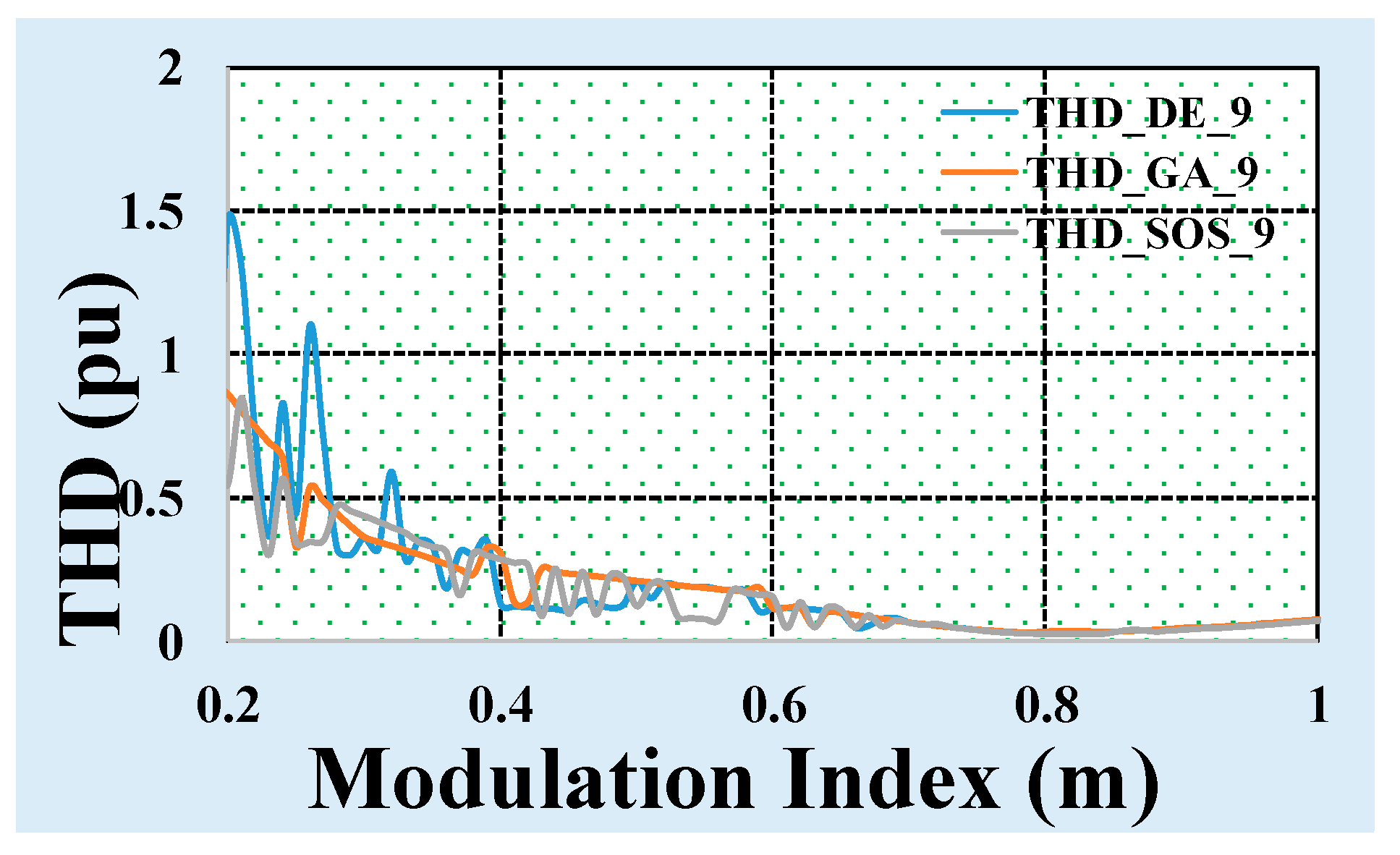
The SOS algorithm is compared with two powerful metaheuristic techniques, i.e., differential evolution and Genetic Algorithm. The THD curve for the three algorithms for nine-level output is shown in
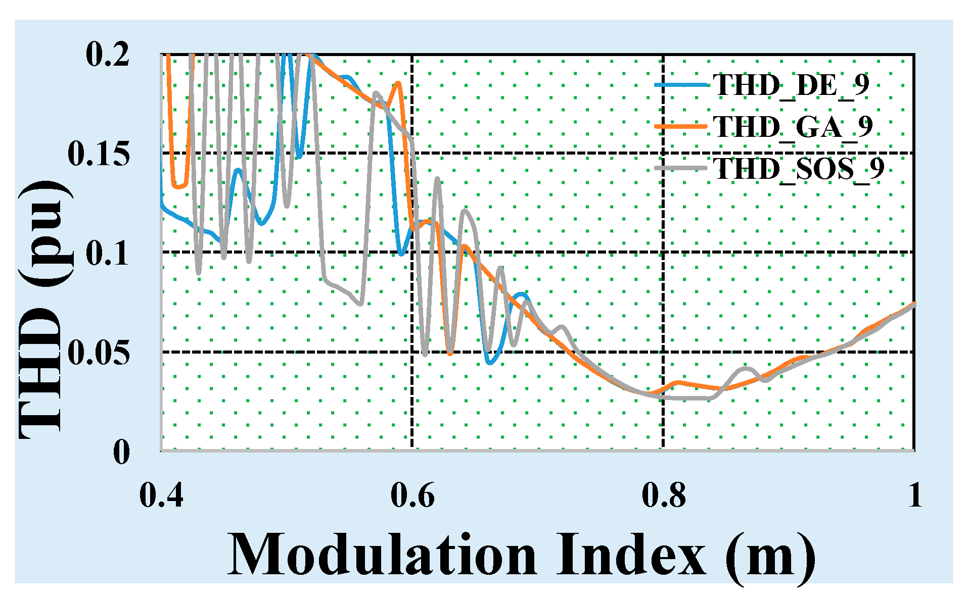
Figure 8. It could be observed that the THD obtained by using the SOS algorithm for a wide range of modulation indexes is less than DE and GA, especially for higher modulation indexes. The Y-axis is zoomed-in
Figure 9 to show the THD value in the three cases clearly. Thus, this is a significant advantage of using the SOS algorithm: the THD has a lower value for a range of modulation indexes.
6.2. Simulation Results
The proposed nine-level SCMLI topology has been simulated in a Simulink environment.
Table 2 shows the parameters used in the simulation study. Simulation results are taken across the load, with the angles corresponding to the modulation index, M = 1.
Figure 10 shows three-phase voltages for three cycles from 0.02 s to 0.08 s, which illustrates that 120° displaces all phase voltages and their amplitude reaches 200 V and signifies twice voltage boosting capability of the nine-level SCMLI.
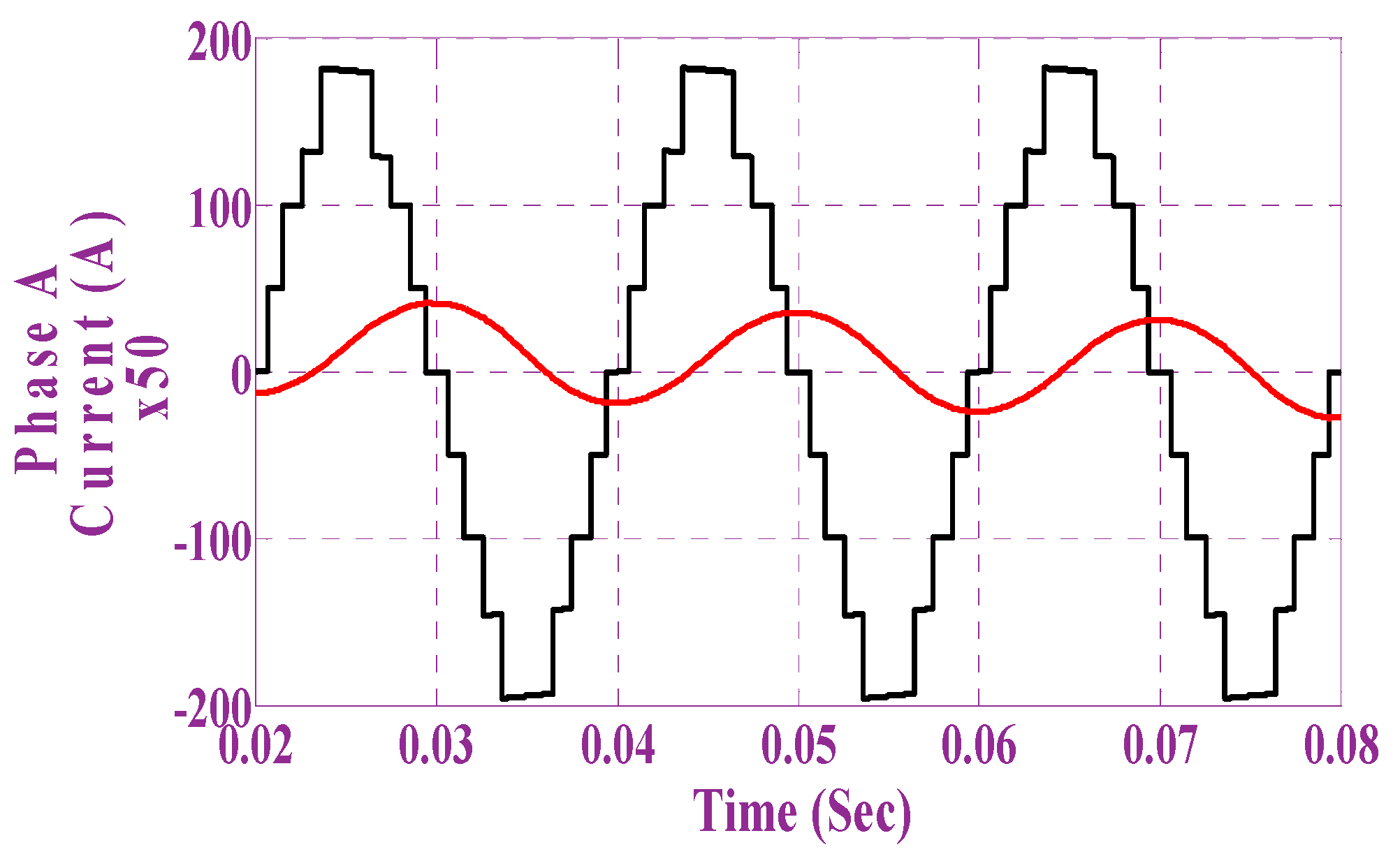
Figure 11 shows the phase voltage (volts) and phase current (A) (multiplied by a gain of 50 to make it visible) for phase A with RL load, which approximates the sinusoidal waveform across the load. The FFT analysis of the phase voltage has been carried out to validate the elimination of the undesired harmonics, as shown in
Figure 12. It is evident that the fundamental voltage is 100%, whereas the 5
th, 7
th and 11
th order harmonics are minimized to a negligible value, and the total harmonic distortion (THD) has reduced to 12.46%. These significant harmonic components go on diminishing with the increase in modulation index, as shown in
Figure 13.
The harmonic representation in
Figure 13 shows the variation of different harmonics amplitude in p.u. with the variation of modulation index. High value of the 3rd harmonic in the lower harmonic index range indicates that there is no solution for 3rd harmonic elimination in that range.
6.3. Hardware in-the-Loop Results for the SHE Implementation Using the SOS Algorithm
The proposed SCMLI topology was modeled in Typhoon’s HIL platform to validate the simulation result. The Typhoon’s HIL platform provide real-time results for the modeled system and it is a precursor for developing and testing a hardware prototype. The HIL arrangement is shown in
Figure 14. The three-phase circuit model was developed in Typhoon’s Integrated Development Environment (IDE). The control circuit for SHE for the three-phase SCMLI is also modeled in HIL-IDE. The model is emulated in HIL. The results are observed on the DSO. The parameters in HIL were taken to be the same as in the simulation. The results obtained were found to be in validation with the simulation results. The three-phase voltages across the load are 120° out of phase, and each phase voltage has an amplitude of 200 V. This is shown in
Figure 15.
Figure 16 shows the voltage and current waveforms for one phase, similar to the simulation results in
Figure 11. The three-phase current across the load is shown in
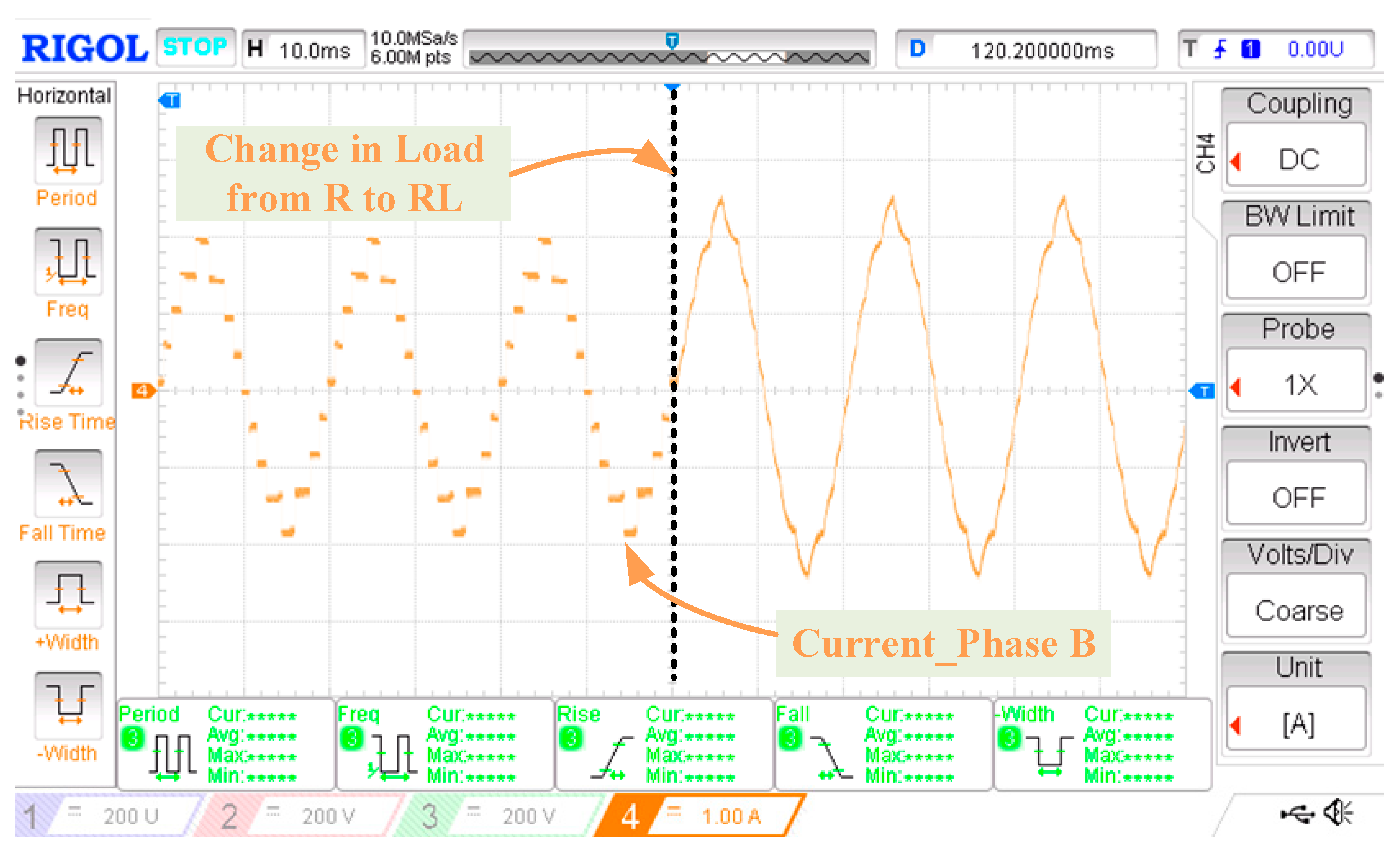
Figure 17. The load current is for the R-L load. The three-phase currents are balanced and close to the sinusoidal waveform. The phase current across a varying load (resistive for three cycles and inductive for three cycles) is shown in
Figure 18. The hardware-in-the-loop results validate the operation of the proposed three-phase SCMLI.
7. Conclusions
In this paper, we examine the operation of the proposed three-phase, nine-stage, multi-stage switched capacitor inverter that utilizes the SOS-based selective harmonic elimination technique. The SOS algorithm to solve SHE equations results in lower THD for a wide range of modulation indexes than the DE and GA algorithm. MATLAB/Simulink results for the nine-level inverter are presented, and FFT analysis has been carried out for one of the phases, demonstrating the elimination of desired lower-order harmonics. The simulation results have been validated through Typhoon’s hardware-in-the-loop testbed.
Author Contributions
Conceptualization, A.S. and M.T.; formal analysis, M.K., A.S., M.T., S.A., and A.S.N.M.; funding acquisition, S.A. and A.S.N.M.; investigation, M.K., A.S. and M.T.; methodology, M.K., A.S., M.T., S.A., A.S.N.M. and E.M.G.R.; supervision, A.S. and M.T.; validation, M.K., A.S. and M.T.; writing—original draft, M.K., A.S. and M.T.; writing—review and editing, S.A., A.S.N.M. and E.M.G.R. All authors have read and agreed to the published version of the manuscript.
Funding
The authors extend their appreciation to King Saud University for funding this work through Researchers Supporting Project number (RSP-2021/387), King Saud University, Riyadh, Saudi Arabia.
Data Availability Statement
Not applicable.
Acknowledgments
The authors extend their appreciation to King Saud University for funding this work through Researchers Supporting Project number (RSP-2021/387), King Saud University, Riyadh, Saudi Arabia.
Conflicts of Interest
The authors declare no conflict of interest.
References
- Villanueva, E.; Correa, P.; Rodriguez, J.; Pacas, M. Control of a Single-Phase Cascaded H-Bridge Multilevel Inverter for Grid-Connected Photovoltaic Systems. IEEE Trans. Ind. Electron. 2009, 56, 4399–4406. [Google Scholar] [CrossRef]
- Rathore, A.K.; Holtz, J.; Boller, T. Generalized Optimal Pulsewidth Modulation of Multilevel Inverters for Low-Switching-Frequency Control of Medium-Voltage High-Power Industrial AC Drives. IEEE Trans. Ind. Electron. 2012, 60, 4215–4224. [Google Scholar] [CrossRef]
- Pereda, J.; Dixon, J. 23-Level Inverter for Electric Vehicles Using a Single Battery Pack and Series Active Filters. IEEE Trans. Veh. Technol. 2012, 61, 1043–1051. [Google Scholar] [CrossRef]
- Kouro, S.; Malinowski, M.; Gopakumar, K.; Pou, J.; Franquelo, L.G.; Wu, B.; Rodriguez, J.; Perez, M.A.; Leon, J.I. Recent Advances and Industrial Applications of Multilevel Converters. IEEE Trans. Ind. Electron. 2010, 57, 2553–2580. [Google Scholar] [CrossRef]
- Rodriguez, J.; Lai, J.-S.; Peng, F.Z. Multilevel inverters: A survey of topologies, controls, and applications. IEEE Trans. Ind. Electron. 2002, 49, 724–738. [Google Scholar] [CrossRef] [Green Version]
- Meynard, T.; Foch, H.; Thomas, P.; Courault, J.; Jakob, R.; Nahrstaedt, M. Multicell converters: Basic concepts and industry applications. IEEE Trans. Ind. Electron. 2002, 49, 955–964. [Google Scholar] [CrossRef]
- Nabae, A.; Takahashi, I.; Akagi, H. A New Neutral-Point-Clamped PWM Inverter. IEEE Trans. Ind. Appl. 1981, IA-17, 518–523. [Google Scholar] [CrossRef]
- Malinowski, M.; Gopakumar, K.; Rodriguez, J.; Perez, M.A. A Survey on Cascaded Multilevel Inverters. IEEE Trans. Ind. Electron. 2009, 57, 2197–2206. [Google Scholar] [CrossRef]
- Siddique, M.D.; Mekhilef, S.; Sarwar, A.; Alam, A.; Shah, N.M. Dual asymmetrical dc voltage source based switched capacitor boost multilevel inverter topology. IET Power Electron. 2020, 13, 1481–1486. [Google Scholar] [CrossRef]
- Peng, F.; McKeever, J.; Adams, D. Cascade multilevel inverters for utility applications. In Proceedings of the IECON’97 23rd International Conference on Industrial Electronics, Control, and Instrumentation (Cat. No. 97CH36066), New Orleans, LA, USA, 14 November 1997; pp. 437–442. [Google Scholar]
- Tolbert, L.M.; Peng, F.Z.; Habetler, T.G. Multilevel converters for large electric drives. IEEE Trans. Ind. Appl. 1999, 35, 36–44. [Google Scholar] [CrossRef] [Green Version]
- Lund, R.; Manjrekar, M.D.; Steimer, P.; Lipo, T.A. Control strategies for a hybrid seven-level inverter. In Proceedings of the European Power Electronic Conference, Lausanne, Switzerland, 7–9 September 1999. [Google Scholar]
- Qawee, A.; Rahim, N.A.; Hasan, K.; Mansour, H.A. Selective harmonic elimination PWM voltage source inverter based on genetic algorithm. In Proceedings of the Recent Trends in Energy Systems Conference (RTES), Cairo, Egypt, 3 October 2015. [Google Scholar]
- Xinchao, Z. A perturbed particle swarm algorithm for numerical optimization. Appl. Soft Comput. 2010, 10, 119–124. [Google Scholar] [CrossRef]
- Wei, H.; Tang, X.-S. A Genetic-Algorithm-Based Explicit Description of Object Contour and its Ability to Facilitate Recognition. IEEE Trans. Cybern. 2014, 45, 2558–2571. [Google Scholar] [CrossRef] [PubMed]
- Shi, K.L.; Li, H. Optimized PWM strategy based on genetic algorithms. IEEE Trans. Ind. Electron. 2005, 52, 1458–1461. [Google Scholar] [CrossRef]
- Ozpineci, B.; Tolbert, L.; Chiasson, J. Harmonic Optimization of Multilevel Converters Using Genetic Algorithms; IEEE: Piscataway, NJ, USA, 2004; Volume 5, pp. 3911–3916. [Google Scholar]
- Ghosh, G.; Basu, A.K.; Seal, S. Finding Optimum Switching Angles Using Genetic Algorithm for SHE-PWM Two-Level Inverter. In Proceedings of the 2019 3rd International Conference on Electronics, Materials Engineering & Nano-Technology (IEMENTech), Kolkata, India, 29–31 August 2019; pp. 1–7. [Google Scholar]
- Bandarua, S.; Debb, K.; Metaheuristic Techniques. COIN Report Number 2016029. Available online: https://www.egr.msu.edu/~kdeb/papers/c2016029.pdf (accessed on 7 December 2021).
- Bhalerao, S.; Pawar, S.; Patwardhan, N. Design and Implementation of Bipolar SHE-PWM Single Phase Inverter for Lower Order Harmonic Suppression. In Proceedings of the 2018 3rd IEEE International Conference on Recent Trends in Electronics, Information & Communication Technology (RTEICT), Karnataka, India, 18–19 May 2018; pp. 1066–1071. [Google Scholar]
- Rajalakshmi, D.; Kavitha, R. Comparison of Selective Harmonic Elimination PWM Technique for Three Phase Matrix Converter with Conventional Algorithms. Int. J. Eng. Adv. Technol. 2018, 8, 2249–8958. [Google Scholar]
- Song, K.; Konstantinou, G.; Mingli, W.; Acuna, P.; Aguilera, R.P.; Agelidis, V.G. Windowed SHE-PWM of Interleaved Four-Quadrant Converters for Resonance Suppression in Traction Power Supply Systems. IEEE Trans. Power Electron. 2017, 32, 7870–7881. [Google Scholar] [CrossRef] [Green Version]
- Wei, C.-L.; Chen, C.-H.; Wu, K.-C.; Ko, I.-T. Design of an Average-Current-Mode Noninverting Buck-Boost DC-DC Converter with Reduced Switching and Conduction Losses. IEEE Trans. Power Electron. 2012, 27, 4934–4943. [Google Scholar] [CrossRef]
- Prajapati, P.; Jayaraman, M.; Sreedevi, V.T. Harmonic elimination in a five level multilevel inverter. In Proceedings of the 2016 International Conference on Computer Communication and Informatics (ICCCI), Coimbatore, India, 7–9 January 2016; pp. 1–6. [Google Scholar]
- Ahmed, M.; Sheir, A.; Orabi, M. Real-Time Solution and Implementation of Selective Harmonic Elimination of Seven-Level Multilevel Inverter. IEEE J. Emerg. Sel. Top. Power Electron. 2017, 5, 1700–1709. [Google Scholar] [CrossRef]
- Bhadra, S.; Gregory, D.; Patangia, H. An analytical solution of switching angles for Selective Harmonic Elimination (SHE) in a cascaded seven level inverter. In Proceedings of the 2016 IEEE 2nd Annual Southern Power Electronics Conference (SPEC), Auckland, New Zealand, 5–8 December 2017; pp. 1–5. [Google Scholar]
- Ben Hamad, K.; Luta, D.N.; Raji, A.K. A Grid-Tied Fuel Cell Multilevel Inverter with Low Harmonic Distortions. Energies 2021, 14, 688. [Google Scholar] [CrossRef]
- Steczek, M.; Jefimowski, W.; Szeląg, A. Application of Grasshopper Optimization Algorithm for Selective Harmonics Elimination in Low-Frequency Voltage Source Inverter. Energies 2020, 13, 6426. [Google Scholar] [CrossRef]
- Srndovic, M.; Familiant, Y.L.; Grandi, G.; Ruderman, A. Time-Domain Minimization of Voltage and Current Total Harmonic Distortion for a Single-Phase Multilevel Inverter with a Staircase Modulation. Energies 2016, 9, 815. [Google Scholar] [CrossRef] [Green Version]
- Jahan, H.K.; Eskandari, R.; Rahimi, T.; Alishah, R.S.; Ding, L.; Bertilsson, K.; Sabahi, M.; Blaabjerg, F. A Limited Common-Mode Current Switched-Capacitor Multilevel Inverter Topology and Its Performance and Lifetime Evaluation in Grid-Connected Photovoltaic Applications. Energies 2021, 14, 1915. [Google Scholar] [CrossRef]
- Cheng, M.-Y.; Prayogo, D.; Tran, D.-H. Optimizing Multiple-Resources Leveling in Multiple Projects Using Discrete Symbiotic Organisms Search. J. Comput. Civ. Eng. 2016, 30, 04015036. [Google Scholar] [CrossRef] [Green Version]
- Tejani, G.; Savsani, V.J.; Patel, V. Adaptive symbiotic organisms search (SOS) algorithm for structural design optimization. J. Comput. Des. Eng. 2016, 3, 226–249. [Google Scholar] [CrossRef] [Green Version]
- Cheng, M.-Y.; Prayogo, D. Symbiotic Organisms Search: A new metaheuristic optimization algorithm. Comput. Struct. 2014, 139, 98–112. [Google Scholar] [CrossRef]
Figure 1.
Nine-level switched capacitor MLI for a phase.
Figure 1.
Nine-level switched capacitor MLI for a phase.
Figure 2.
Three-phase nine-level switched capacitor MLI.
Figure 2.
Three-phase nine-level switched capacitor MLI.
Figure 3.
Operational diagrams of nine-level SCMLI representing different possible output voltage levels: (a) Vo = 2Vdc, (b) Vo = 1.5Vdc, (c) Vo = Vdc, (d) Vo = 0.5Vdc, (e) Vo = 0, (f) Vo = 0, (g) Vo = −0.5Vdc, (h) Vo = −Vdc, (i) Vo = −1.5Vdc, and (j) Vo = −2Vdc.
Figure 3.
Operational diagrams of nine-level SCMLI representing different possible output voltage levels: (a) Vo = 2Vdc, (b) Vo = 1.5Vdc, (c) Vo = Vdc, (d) Vo = 0.5Vdc, (e) Vo = 0, (f) Vo = 0, (g) Vo = −0.5Vdc, (h) Vo = −Vdc, (i) Vo = −1.5Vdc, and (j) Vo = −2Vdc.
Figure 4.
Block diagram of the SOS algorithm applied to the SHE problem.
Figure 4.
Block diagram of the SOS algorithm applied to the SHE problem.
Figure 5.
Switching angles vs. modulation index (varied from 0.01 to 1) for a nine-level output voltage.
Figure 5.
Switching angles vs. modulation index (varied from 0.01 to 1) for a nine-level output voltage.
Figure 6.
Convergence curve for SOS for the SHE nine-level problem with modulation index = 1.
Figure 6.
Convergence curve for SOS for the SHE nine-level problem with modulation index = 1.
Figure 7.
Contour representation of four angles for different modulation indexes (at the end of the third stage).
Figure 7.
Contour representation of four angles for different modulation indexes (at the end of the third stage).
Figure 8.
THD comparison with DE and GA.
Figure 8.
THD comparison with DE and GA.
Figure 10.
Three-phase voltages of the nine-level SCMLI.
Figure 10.
Three-phase voltages of the nine-level SCMLI.
Figure 11.
Phase voltage and current for the nine-level SCMLI with RL load.
Figure 11.
Phase voltage and current for the nine-level SCMLI with RL load.
Figure 12.
Harmonic spectrum of the voltage across phase A.
Figure 12.
Harmonic spectrum of the voltage across phase A.
Figure 13.
Harmonic components present in the voltage across phase A.
Figure 13.
Harmonic components present in the voltage across phase A.
Figure 14.
Real-time implementation of the proposed three-phase SCMLI with an SOS-SHE modulation scheme.
Figure 14.
Real-time implementation of the proposed three-phase SCMLI with an SOS-SHE modulation scheme.
Figure 15.
HIL result: three-phase voltages of nine-level SCMLI.
Figure 15.
HIL result: three-phase voltages of nine-level SCMLI.
Figure 16.
HIL result: voltage and current waveform for RL load.
Figure 16.
HIL result: voltage and current waveform for RL load.
Figure 17.
HIL result: phase currents through the three-phase load.
Figure 17.
HIL result: phase currents through the three-phase load.
Figure 18.
HIL result: phase B current when load changes from R to RL.
Figure 18.
HIL result: phase B current when load changes from R to RL.
Table 1.
Switching states of the basic unit of the proposed SCMLI.
Table 1.
Switching states of the basic unit of the proposed SCMLI.
| S1 | S2 | S3 | S4 | S5 | S6 | S7 | S8 | S9 | S10 | Vo | VC3 |
|---|
| 0 | 1 | 0 | 1 | 0 | 0 | 1 | 1 | 1 | 0 | 2 Vdc | D |
| 0 | 0 | 1 | 1 | 0 | 0 | 1 | 1 | 1 | 0 | 1.5 Vdc | D |
| 0 | 1 | 0 | 1 | 1 | 1 | 1 | 0 | 1 | 0 | Vdc | C |
| 0 | 0 | 1 | 1 | 0 | 1 | 0 | 0 | 1 | 0 | 0.5 Vdc | ─ |
| 1 | 0 | 0 | 1 | 0 | 1 | 0 | 0 | 1 | 0 | 0 | ─ |
| 0 | 1 | 0 | 0 | 1 | 0 | 1 | 0 | 0 | 1 |
| 0 | 0 | 1 | 0 | 1 | 0 | 1 | 0 | 0 | 1 | −0.5 Vdc | ─ |
| 1 | 0 | 0 | 1 | 1 | 1 | 1 | 0 | 0 | 1 | −Vdc | C |
| 0 | 0 | 1 | 0 | 1 | 1 | 0 | 1 | 0 | 1 | −1.5 Vdc | D |
| 1 | 0 | 0 | 0 | 1 | 1 | 0 | 1 | 0 | 1 | −2 Vdc | D |
Table 2.
Components and parameters of nine-level topology.
Table 2.
Components and parameters of nine-level topology.
| Component’s Name | Specification |
|---|
| DC input voltage source (Vdc) | 100 V |
| Capacitors (C1, C2 and C3) | 4.7 mF |
| RL load | 100 Ω,10 mH |
| Output voltage (Vo) | 200 V |
| Output frequency | 50 Hz |
| Publisher’s Note: MDPI stays neutral with regard to jurisdictional claims in published maps and institutional affiliations. |
© 2021 by the authors. Licensee MDPI, Basel, Switzerland. This article is an open access article distributed under the terms and conditions of the Creative Commons Attribution (CC BY) license (https://creativecommons.org/licenses/by/4.0/).


 ,
, 


