Article

Comparison of Interleaving Methods of Parallel Connected Three-Level Bi-Directional Converters

1
Department of Control and Instrumentation Engineering, Korea University of Transportation, Chungju 27469, Korea
2
Propulsion System Research Department, Korea Railroad Research Institute, Uiwang 16015, Korea
*
Authors to whom correspondence should be addressed.
Energies 2022, 15(1), 6; https://doi.org/10.3390/en15010006
Submission received: 27 October 2021 / Revised: 22 November 2021 / Accepted: 10 December 2021 / Published: 21 December 2021
(This article belongs to the Topic Application of Innovative Power Electronic Technologies)

Abstract

:
The voltage and current ripples in the three-level bi-directional converter (TLBC) can be reduced by an interleaving technique that controls a phase difference between the modules of power converter. On the other hand, the inductor current ripple in TLBC is increased due to the circulating current between the modules. In this paper, the effects of two interleaving methods on a two-phase TLBC, Z-type and N-type, are investigated and compared. In particular, capacitor current ripple, and voltage ripple are compared by two interleaving methods verified through Powersim (PSIM) simulation.

1. Introduction

In the transportation facilities including electric locomotive and electric vehicle, the kinetic energy in braking mode is converted into the electrical energy. This regenerative energy generated by the electric machine can be stored in a battery by a bidirectional power converter [1,2,3]. The high voltage semiconductor switches are required in such high power, high voltage applications, and this results in large losses in semiconductor switches. Therefore, research on three-level bidirectional converter (TLBC) is being actively carried out to lower the voltage stress of power semiconductors [4,5,6,7]. Figure 1 shows a TLBC circuit.
Because the TLBC in Figure 1 has a structure in which the two-level bidirectional converters are vertically symmetric, the voltage stress of the switching devices is reduced by half. This makes it feasible to reduce the loss of the elements [8]. Furthermore, the ripple of the inductor and output currents, and output voltage can be reduced by half. A decrease in the ripple of current and voltage has a positive effect on the lifespan and efficiency of passive elements [9,10,11,12].
In addition, if the power converter is configured in parallel, it can provide benefits such as the reduction of losses and heat dissipation under heavy loads, and increase in power capacity [13,14]. TLBCs that are configured in parallel generally perform interleaving operations with a phase difference on one period [5,15]. In this case, each pair of switches operate alternately so that the input current, output current and voltage ripples can be reduced. However, by the interleaving control, a circulating current is generated, which flows from the inductor of one module to that of the other module. This increases the ripple of the current flowing through the inductor [16,17]. An increase in the ripple of the inductor current results in an increase in the loss of the inductor as well as a decrease in the efficiency of the converter module. There are two interleaving methods, Z-type and N-type, in TLBCs with two-phase parallel configuration according to the order of operating switches [18]. N-type interleaving operates all the switches of one module first and then those of another. In contrast, Z-type interleaving operates the high-side switches of all the modules first and then the low-side switches. In the case of Z-type interleaving, because the phase difference between the high-side switches is smaller than that for N-type interleaving, the amount of circulating current generated between the modules of Z-type interleaving is smaller then that of N-type interleaving.
The effect of the interleaving method on the inductor current has been analyzed extensively in the reference document [18]. However, the effects on the filter capacitor are not discussed in that paper. Generally, filter capacitors can be the largest failure’s sources of converter modules [19]. Therefore, in this study, the effects of interleaving methods on the filter capacitor of the current of the filter capacitor was analyzed according to the two interleaving operation methods for the two phase parallel TLBC structure. Furthermore, the control methods of two types interleaving were also analyzed. The analysis results were verified through Powersim (PSIM) simulations. This paper is organized as follows: Section 2 describes the basic operation of two-phase parallel TLBCs. Section 3 analyzes the current ripple of the filter capacitor and the control method that depend on the interleaving method. Section 4 verifies the analytical results given in Section 3 by simulations. Finally, conclusions are presented in Section 5.

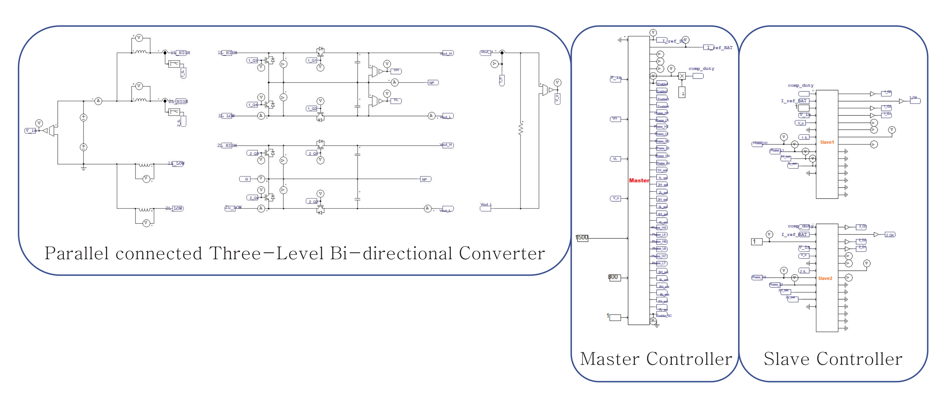
2. Parallel Operation of Two-Phase Parallel TLBC

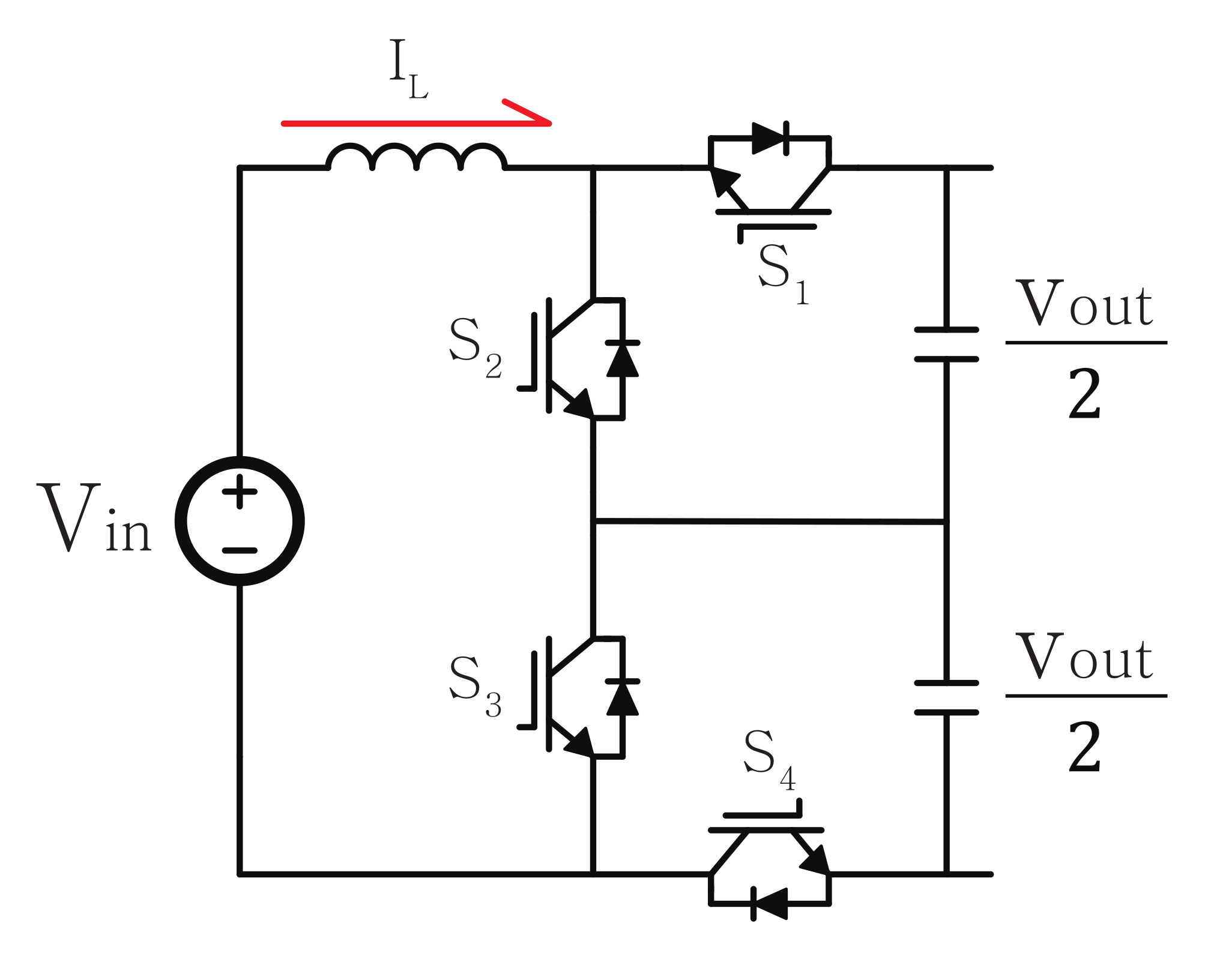
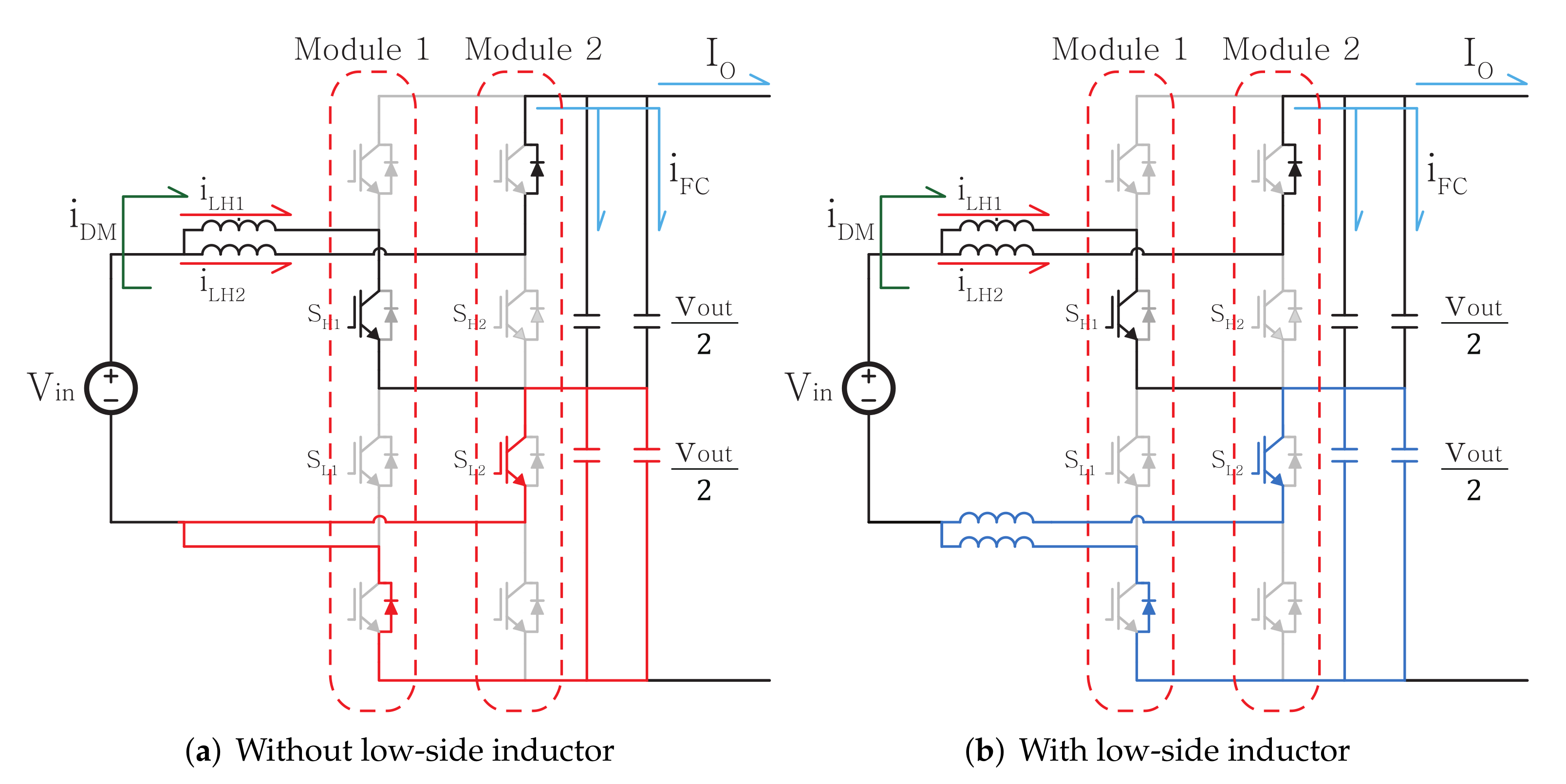
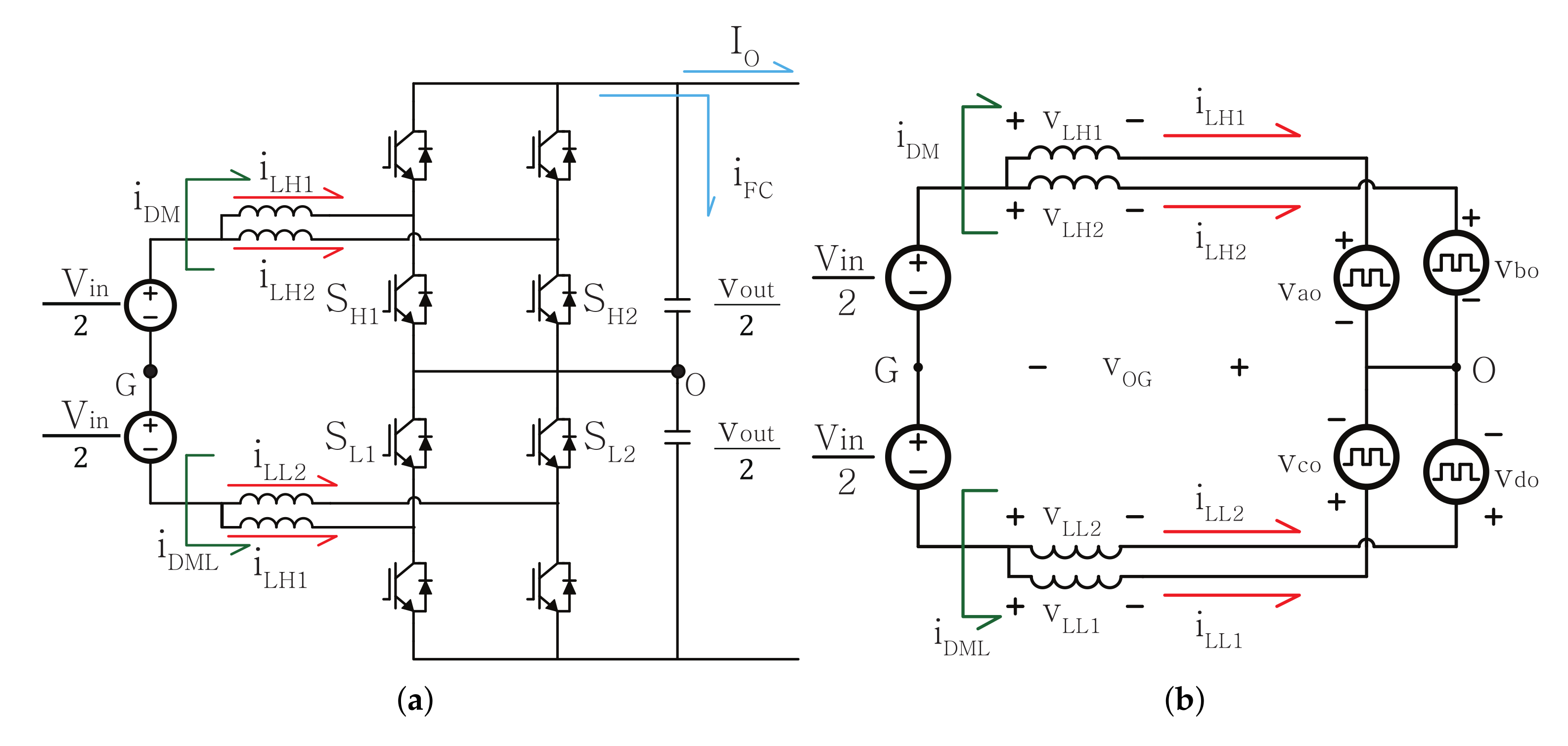
2.1. Circuit of Two-Phase Parallel TLBC

To configure TLBCs in parallel, two aspects need to be considered in connecting single TLBC. Firstly, the neutral points of the two capacitors placed between the high-side and low-side in the TLBCs in parallel must be connected. By connecting the neutral point, the current ripple of the capacitor is divided between capacitors connected in parallel, which reduces the loss of the capacitor and increases the lifespan [20]. Second, a low-side inductor must be added to prevent the short-circuiting of low-side capacitors. While interleaving the TLBC, there is a switching instance in which two low-side capacitors are short circuited. Figure 2a illustrates the low-side capacitors are short-circuited during interleaving control in TBLC.
In such a case, the entire output voltage is applied to the high-side capacitors so that these capacitors may be destroyed by over voltage failure. Therefore, a low-side inductor should be added to prevent short circuit failure of the low-side capacitor. Figure 2b illustrates a circuit diagram of a two-phase TLBC configured in parallel with an inductor at the bottom. As described above, the two-phase parallel TLBC circuit used in this study has low-side inductors, and the neutral points of capacitors in each module are connected.

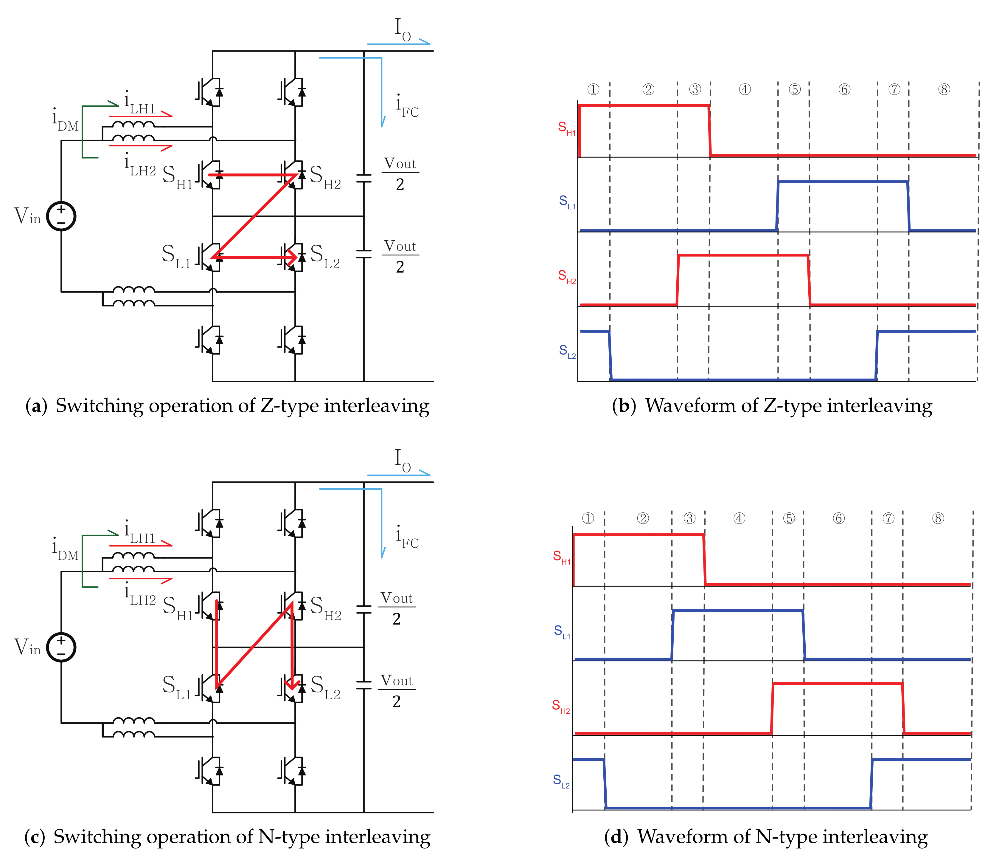
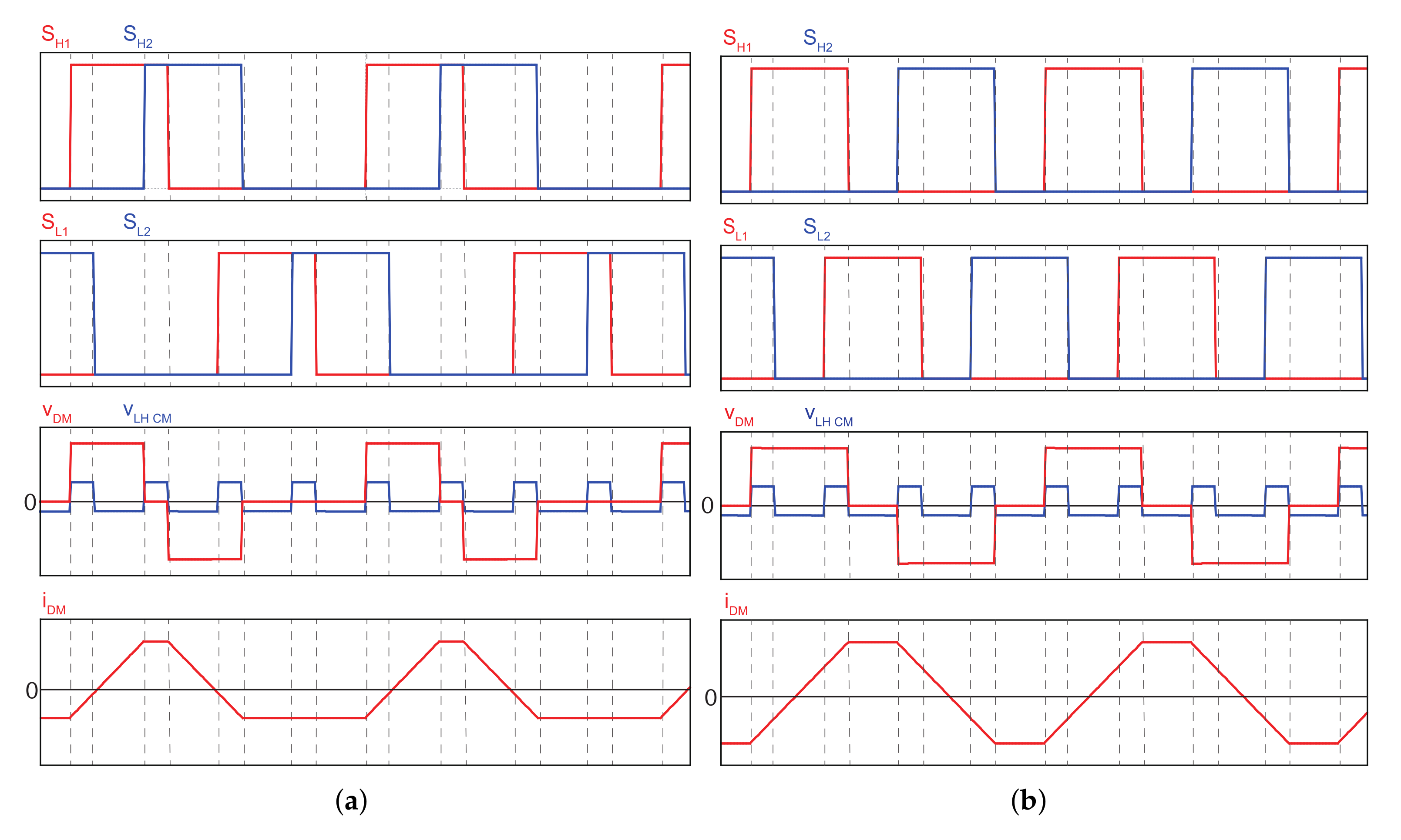
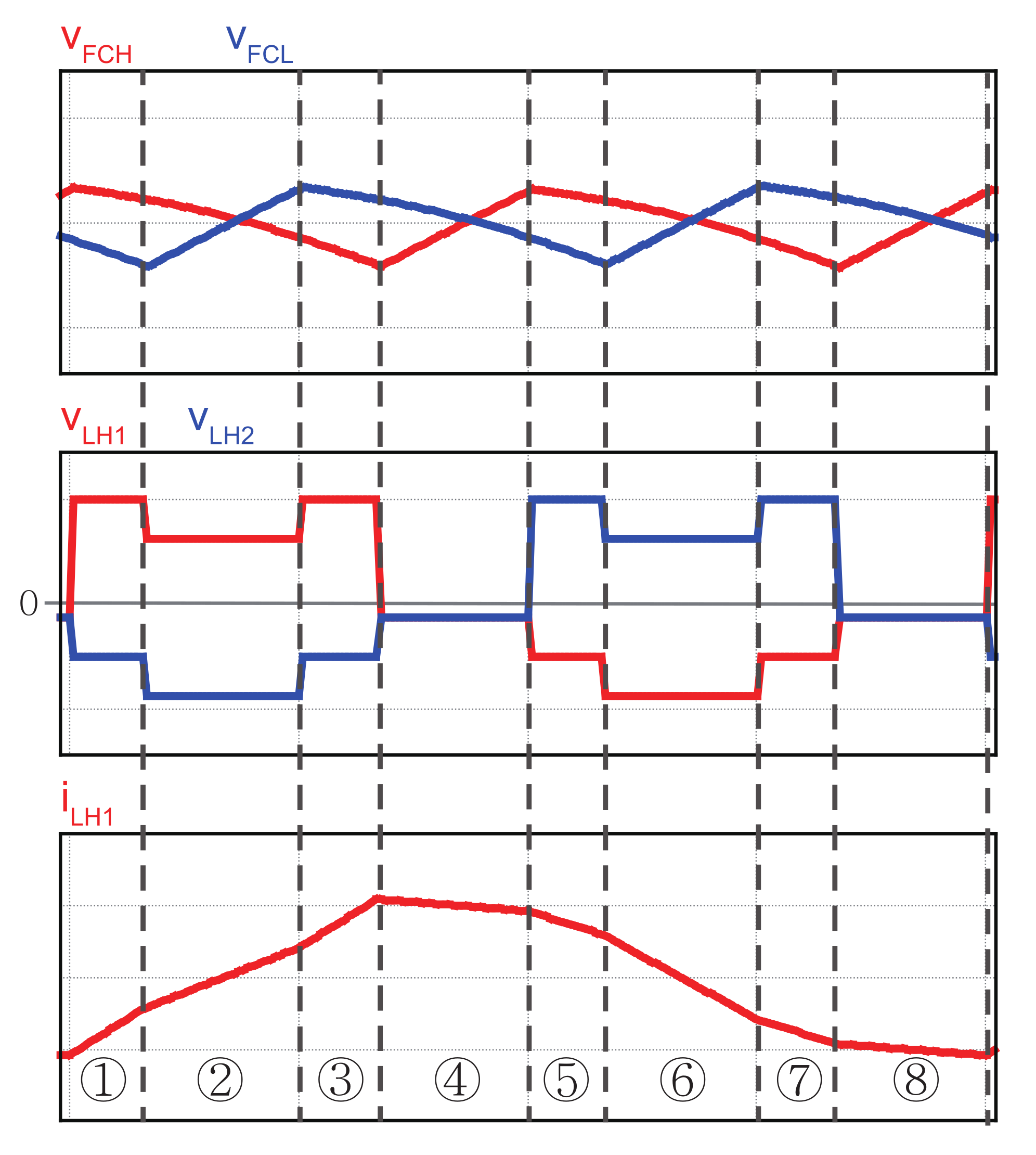
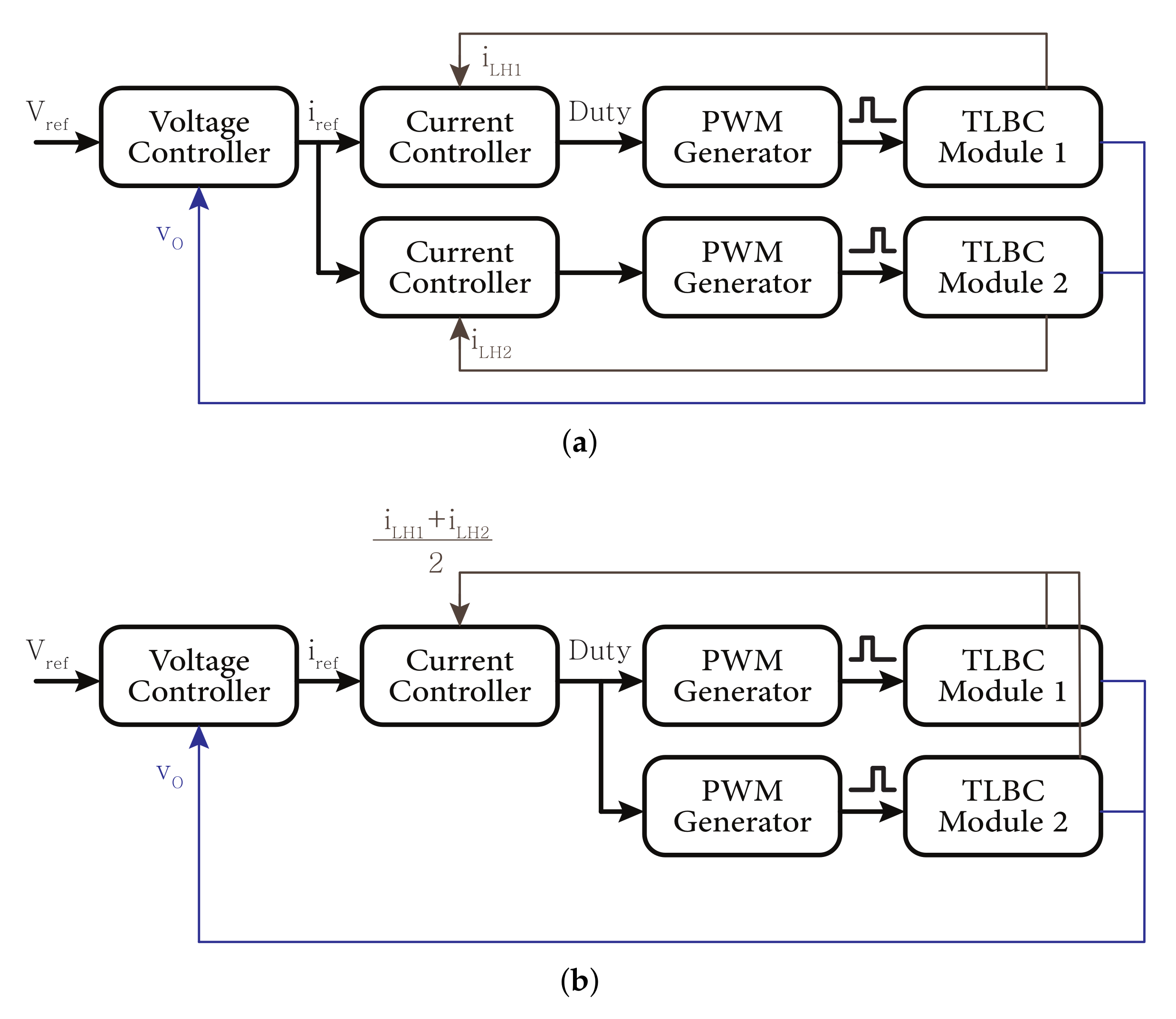
2.2. Interleaving Methods of 2 Parallel Three-Level Bi-Directional Converters

In the conventional single-phase TLBC, the two switches at the high-side and low-side operate with a phase difference of 180°. However, because there are a total of four activated switches in the two-phase parallel TLBC, it must operate with a phase difference of 90° (obtained by dividing a cycle into four parts). At this time, it is categorized as N-type or Z-type interleaving according to the order of phase difference [18]. Figure 3 illustrates the switching sequence for two types of interleaving methods, N-type and Z-type. Moreover, the two filter capacitors connected in parallel are expressed equivalently as one capacitor. In N-type interleaving, the switches of first module operate in the top and bottom order, then those of second module operate in the top and bottom order—while, in Z-type interleaving, the high-side switches of two modules are turned on sequentially and then the low-side switches are turned on.
Meanwhile, a circulating current ( I D M ) is generated when the parallel modules are subjected to interleaving control. This circulating current is not completely transferred to the output power, but it flows into another module. This circulating current increases the power losses as well as a current ripple of the inductor. The next section describes the circulating current for two types of interleaving methods.

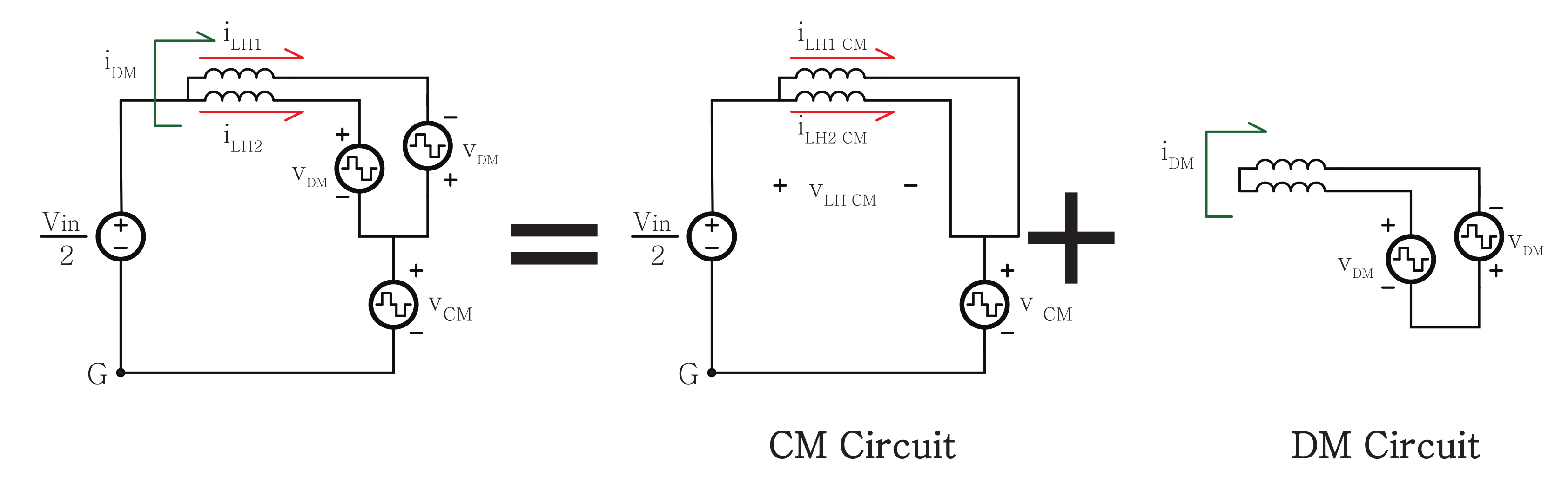
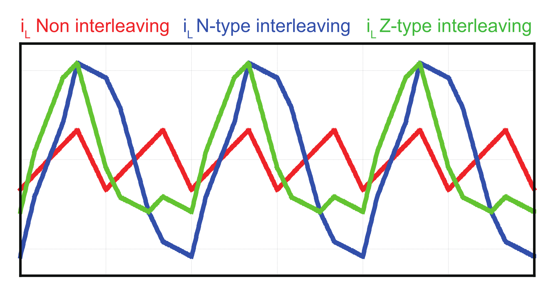
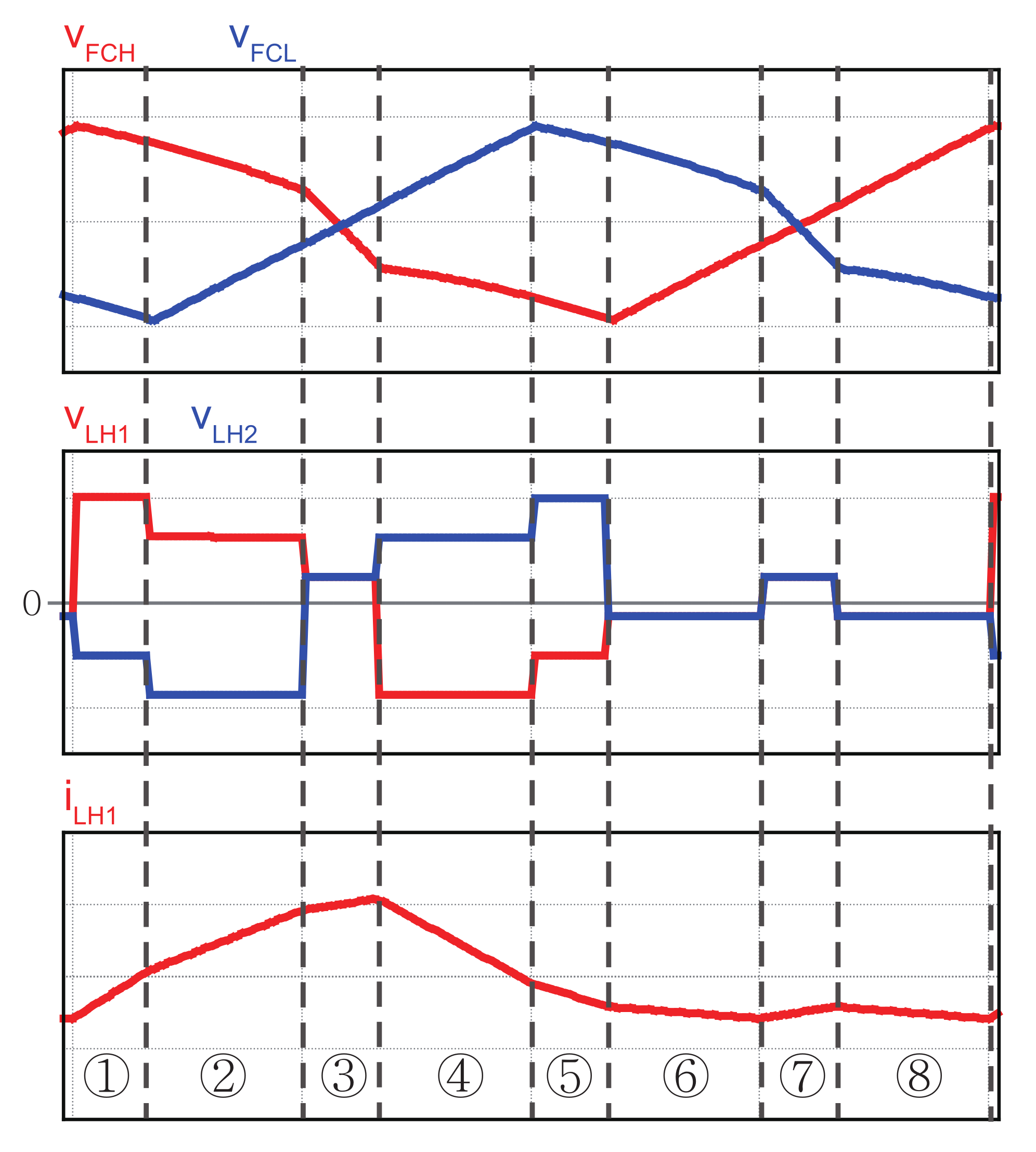
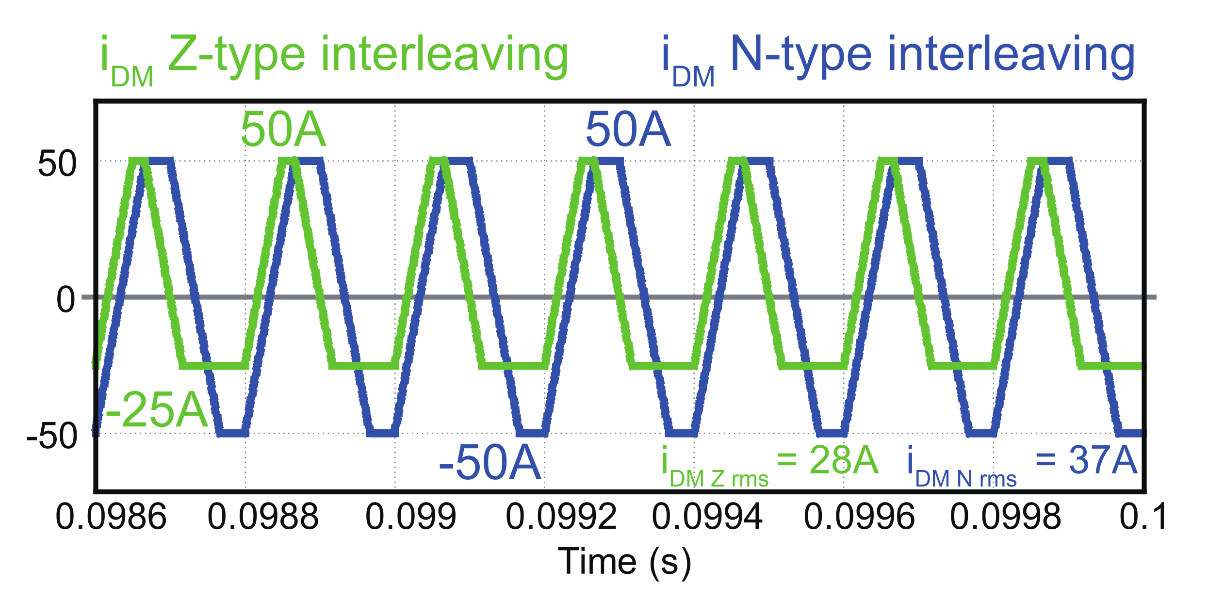
2.3. Circulating Current Variation with an Interleaving Method

The circulating current ( i D M ) flowing between the modules owing to interleaving control and the common current ( i C M ) flowing to the output terminal (without flowing to another module) are defined as in Equations (1) and ():
i C M = i L H 1 + i L H 2 2
i D M = i L H 1 i L H 2 2
where i L H 1 and i L H 2 refer to inductor currents flowing through the high-side inductors of modules 1 and 2, respectively. The inductor current of each module can be expressed as Equations (3) and () using the circulation current and common current
i L H 1 = i C M + i D M
i L H 2 = i C M i D M
Figure 4a shows the circuit diagram of two-phase parallel TLBC. Figure 4b shows an equivalent circuit obtained by replacing the switch and output voltage terminal of a two-phase parallel TLBC with a square wave voltage source. Point G, which is the middle point of the input voltage, is a virtual node. Point O, which is the neutral point of the capacitor, is defined as a node for interpreting the circuit by dividing it into high-side and low-side ends.
The voltages applied to the inductor in Figure 4 ( v L H 1 , v L H 2 , v L L 1 , v L L 2 ) can be expressed by Equations (5)–(8):
v L H 1 = v i n 2 v O G v a o
v L H 2 = v i n 2 v O G v b o
v L L 1 = v i n 2 v O G v c o
v L L 2 = v i n 2 v O G v d o
where the square wave voltage sources v a o , v b o , v c o and v d o mean voltages corresponding to half of the output voltage according to the operation of the switch. v a o , v b o , v c o ,and v d o are expressed by Equations (9)–(12):
v a o = ( 1 S H 1 ) v o u t 2
v b o = ( 1 S H 2 ) v o u t 2
v c o = ( 1 S L 1 ) v o u t 2
v d o = ( 1 S L 2 ) v o u t 2
where S H 1 , S H 2 , S L 1 , S L 2 represent switching functions of the high-side switch of module 1, the high-side switch of module 2, the low-side switch of module 1, and the low-side switch of module 2, respectively. Equation (13) defines a switch function. It is defined that the value of switching function is one when the switch is on and zero when it is off.
S H 1 = 1 Switch S H 1 is On 0 Switch S H 1 is OFF , S H 2 = 1 Switch S H 2 is On 0 Switch S H 2 is OFF S L 1 = 1 Switch S L 1 is On 0 Switch S L 1 is OFF , S L 2 = 1 Switch S L 2 is On 0 Switch S L 2 is OFF
The neutral voltage of the output capacitor v O G can be derived by applying KCL (Kirchhoff’s current law) to point O as follows:
i L H 1 + i L H 2 + i L L 1 + i L L 2 = 0 v L H 1 Z + v L H 2 Z + v L L 1 Z + v L L 2 Z = 0 v L H 1 + v L H 2 + v L L 1 + v L L 2 = 0
where Z denotes the impedance of each inductor (it is assumed that the inductors have equal impedance). The following equation is obtained when it is substituted into Equations (5)–(8):
4 v O G v a o v b o v c o v d o = 0
Finally, the neutral voltage v O G can be expressed as follows from Equations (9), () and (15):
v O G = ( S H 1 + S H 2 S L 1 S L 2 ) v o u t 8
The high-side inductor voltages ( v L H 1 , v L H 2 ) according to the switch operation in the circuit can be rearranged by Equations (17) and ():
v L H 1 = v i n 2 v O G v a o
= v i n 2 + ( 3 S H 1 S H 2 + S L 1 + S L 2 4 ) v o u t 8 v L H 2 = v i n 2 v O G v b o
= v i n 2 + ( S H 1 + 3 S H 2 + S L 1 + S L 2 4 ) v o u t 8
It is difficult to distinguish the common current from the circulating current in Figure 4b; therefore, the interpretation is carried out by dividing the common mode (CM) circuit that generates a common current and the differential mode (DM) circuit that generates the circulating current. Figure 5 illustrates the two-phase parallel three-level converters divided into a CM circuit and a DM circuit. The voltages across the high side inductors in the CM circuit have the same polarity, whereas those in the DM circuit have the opposite polarity.
The v C M expressed in Figure 5 is defined by the sum of the mean of v a o and v b o , and v O G (Equation (19)). In addition, v D M is defined by half of difference of v a o and v b o (Equation (21)). Furthermore, these voltages can be expressed by switching functions as given in Equations (20) and (22):
v C M = v a o + v b o 2 + v O G
= ( 4 ( S H 1 + S H 2 + S L 1 + S L 2 ) ) v o u t 8
v D M = v a o + v b o 2
= ( S H 1 S H 2 ) 4 v o u t
Here, v L H 1 and v L H 2 can be expressed by Equations (23) and (24), using v C M and v D M , respectively:
v L H 1 = v i n 2 v C M + v D M
v L H 2 = v i n 2 v C M v D M
Moreover, the high-side inductor voltage v L H C M in the CM circuit can be expressed as Equation (25) according to the Kirchhoff voltage law of the CM circuit:
v L H C M = v i n 2 v C M = v i n 2 + ( S H 1 + S H 2 + S L 1 + S L 2 4 ) v o u t 8
Figure 6 shows the switching waveforms ( S H 1 , S H 2 , S L 1 , and S L 2 ) for the Z-type and N-type interleaving method, the common mode inductor voltages ( v L H C M ), the differential mode inductor voltages ( v D M ), and the circulating currents ( i D M ). The common mode voltages across high-side inductors for each module ( v L H C M ) generate the common current, and the differential mode voltages generate a circulating current.
As shown in Figure 6, the time in differential mode operation for Z-type interleaving is shorter than for N-type interleaving so that the circulating current for Z-type interleaving is smaller than that for N-type interleaving. The increase in the circulating current increases the ripple of the inductor current. Figure 7 illustrates the inductor current i L according to the interleaving method. The inductor current ripple in Z-type interleaving is smaller than that in N-type interleaving due to the small circulating current. This implies that the inductor losses in Z-type interleaving can be smaller than that of N-type interleaving. In the aspect of filter capacitor, however, different results may be obtained. This will be discussed in the next section.

3. Comparison of Interleaving Methods for Capacitor’s Current and Voltage

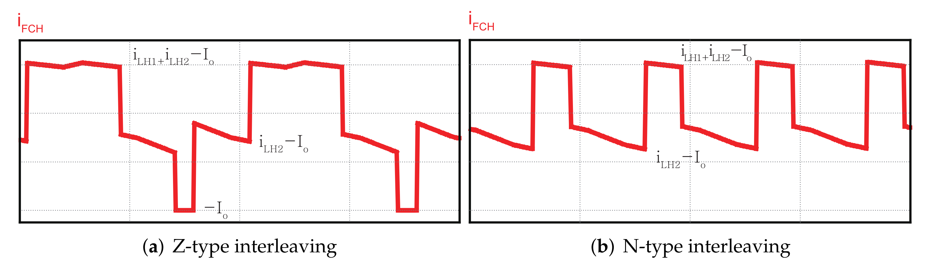
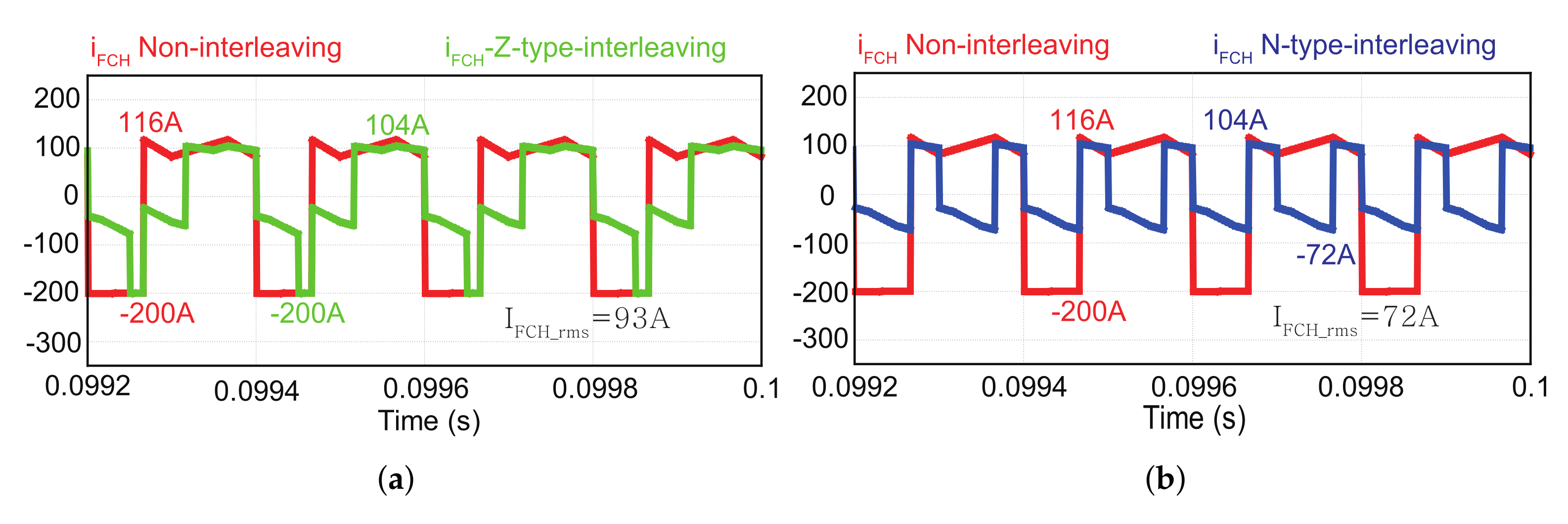
3.1. Impact of Interleaving on Capacitor Current Ripple of Parallel TLBC

The effect of interleaving of the two-phase parallel TLBC on the inductor current is analyzed extensively in the reference document [18]. However, the effect on the filter capacitor is not discussed. Therefore, in this study, the effect of the interleaving method on the filter capacitor of the two-phase parallel TLBC is analyzed. The current ripple of the filter capacitor is related to the rms value of the capacitor current that is proportional to heat loss generated in the capacitor. Equation (26) represents the loss due to the equivalent series resistance (ESR) of the capacitor:
P C L o s s = i c r m s 2 R C E S R
Increased heat and loss adversely affect the capacitor lifespan and reduce the converter’s efficiency. Capacitor is foremost among the causes of failure in converter modules; therefore, a capacitor’s lifespan is directly related to that of the converter module [19]. The current ripple of the filter capacitor is an important indicator of the converter’s lifetime. Hence, it is essential to consider the effect of the interleaving methods on the current ripple of the capacitor, which will be discussed in Section 3.1.1 and Section 3.1.2.

3.1.1. Capacitor Current for Z-Type Interleaving

First, this section discusses the case of Z-type interleaving. Figure 3a illustrates the operating modes and switching status for Z-type interleaving method. As mentioned earlier, the high-side switches of each module operate prior to the low-side switches.
Based on the operation of the switch, a cycle of operational modes was divided into eight states. As illustrated in Figure 8, the current of the high-side and low-side capacitors according to the switching states the switch operation is expressed as Equations (27) and (28):
i F C H = ( 1 S H 1 ) i L H 1 + ( 1 S H 2 ) i L H 2 I o
i F C L = ( 1 S L 1 ) i L L 1 + ( 1 S L 2 ) i L L 2 I o .
For example, in state 1, the high-side switch of module 1 and low-side switch of module 2 are turn-on, and the positive terminal of the high-side capacitor is connected to the high-side inductor of module 2 and the output terminal (see Figure 8a). Thus, the current of the high-side capacitor i F C H can be expressed as the difference between the high-side inductor current of module 2 and the output current by Kirchhoff’s current law. Equation (29) represents the current i F C H flowing through the high-side capacitor at state 1, as the difference of the high-side inductor current i L H 2 of module 2 and the output current I o :
i F C H = i L H 2 I o
In addition, in state 3, only the high-side switches of module 1 and 2 ( S H 1 , S H 2 ) are turned on, and the positive terminal of the high-side capacitor is connected only to the output terminal (see Figure 8). This implies that the inductor currents are separated from the capacitors, and the output current is supplied by only capacitors. The current flowing through the high-side capacitor i F C H at state 3 is expressed as Equation (30):
i F C H = I o
From this analysis, the current of the high-side filter capacitor in each state can be obtained, as shown in Table 1. The current of the low-side filter capacitor can also be obtained similarly. As shown in Table 1, the high-side capacitor current i F C H in eight states for Z-type interleaving can be expressed by the high-side inductor currents of modules 1 and 2 ( i L H 1 and i L H 2 ) and the output current Io.

3.1.2. Capacitor Current for N-Type Interleaving

This section describes the capacitor current ripple for N-type interleaving. Figure 3b of the previous section presents a switching pattern for N-type interleaving method. Unlike Z-type interleaving (where the high-side switches of the two modules turn-on first and then the low-side switches turn-on), the high-side and low-side switches of one module turn-on first and then those of the other module turn-on in N-type interleaving.
As in the case of Z-type interleaving, a cycle was divided into eight states according to the operation of the switch. As shown in Figure 9, in state 1, a high-side switch of module 1 and a low-side switch of module 2 are turned on (this is similar to the case of Z-type interleaving), and a positive terminal of the high-side capacitor is connected to a high-side inductor of module 2 and an output terminal. Therefore, the current of the high-side capacitor i F C H can be expressed as the difference between the high-side inductor current of module 2 and the output current using Kirchhoff’s current law. This is similar to state 1, Equation (29) of Z-type interleaving. However, states 3 and 4 alongside states 6 and 7 appear differently. For example, in state 4 of Z-type interleaving, all of the high-side switches of modules 1 and 2 are turned off. At this time, the positive terminals of the high-side capacitor are connected to both the high-side inductors and output terminals of modules 1 and 2. Therefore, the current of the top capacitor i F C H in the corresponding state can be expressed as the difference between the sum of the top inductor currents of modules 1 and 2 and the output current. Equation (31) represents the high-side capacitor current i F C H at state 4 during N-type interleaving as a function of the high-side inductor currents of modules 1 and 2 ( I L H 1 and I L H 2 ) and the output current I o :
i F C H = i L H 1 + i L H 2 I o
This is different from i L H 1 I o which is i F C H in state 7 of N-type interleaving. At the remaining states 3, 6, and 7, the Z-type and N-type interleaving yield different results. Table 2 illustrates the current of the high-side capacitor i F C H in each state according to the operating modes for n-type interleaving with the high-side inductor currents of modules 1 and 2 ( i L H 1 and i L H 2 ) and the output current I o .
The capacitor current was analyzed for two types of interleaving methods. The current ripple behavior for both interleaving methods appears differently due to a certain state in Z-type interleaving, which is absent in N-type interleaving. The high-side capacitor current of state 3, which exists only in the Z-type interleaving method, is equal to I o . This is an important contributing factor for the increase in the capacitor current ripple. Figure 10 illustrates the high-side capacitor current waveforms for each interleaving method. This was verified in the simulation described in Section 4.

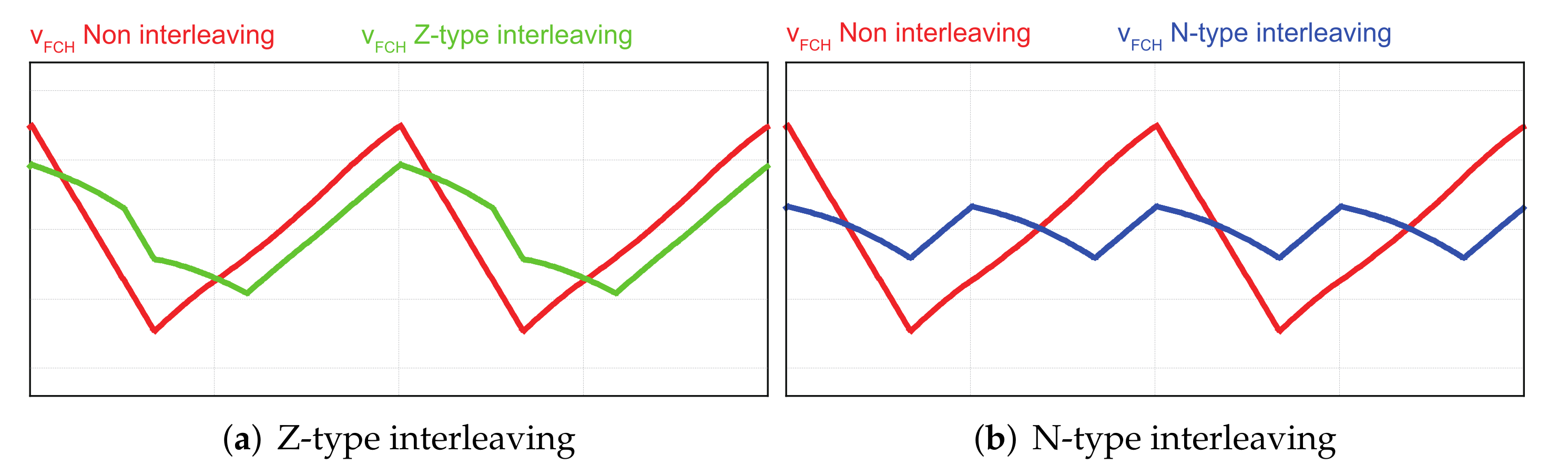
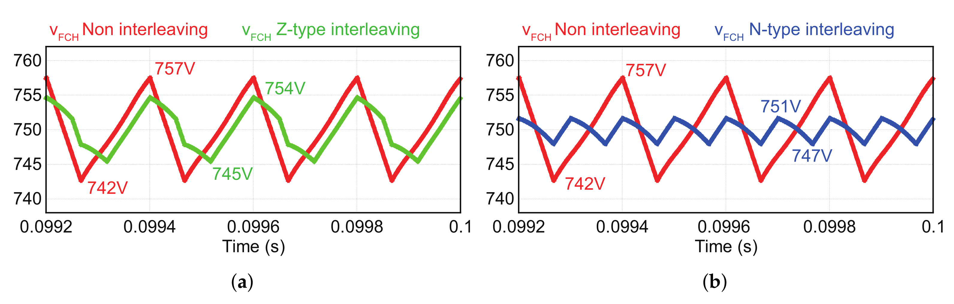
3.2. Comparative Analysis of Capacitor Voltage

The disadvantages of Z-type interleaving control include not only an increase in loss and a decrease in the lifespan of the capacitor due to an increase in the capacitor current ripple but a negative impact on EMI. Figure 11 shows the high-side capacitor voltages according to the interleaving method.
Figure 11 shows the high-side capacitor voltage waveforms for Z-type and N-type interleaving. The capacitor voltage of Z-type interleaving has similar waveforms to the conventional non-interleaving control, and the capacitor current is charged and discharged once per cycle. However, the high-side capacitor charges and discharges twice per cycle in N-type interleaving so that the capacitor voltage ripple is decreased. When the ripple frequency is doubled, similar to the voltage of the high-side capacitor in N-type interleaving, the cutoff frequency of the EMI filter can be increased. This enables the EMI filter size to be reduced, thereby leading to price reduction [21].

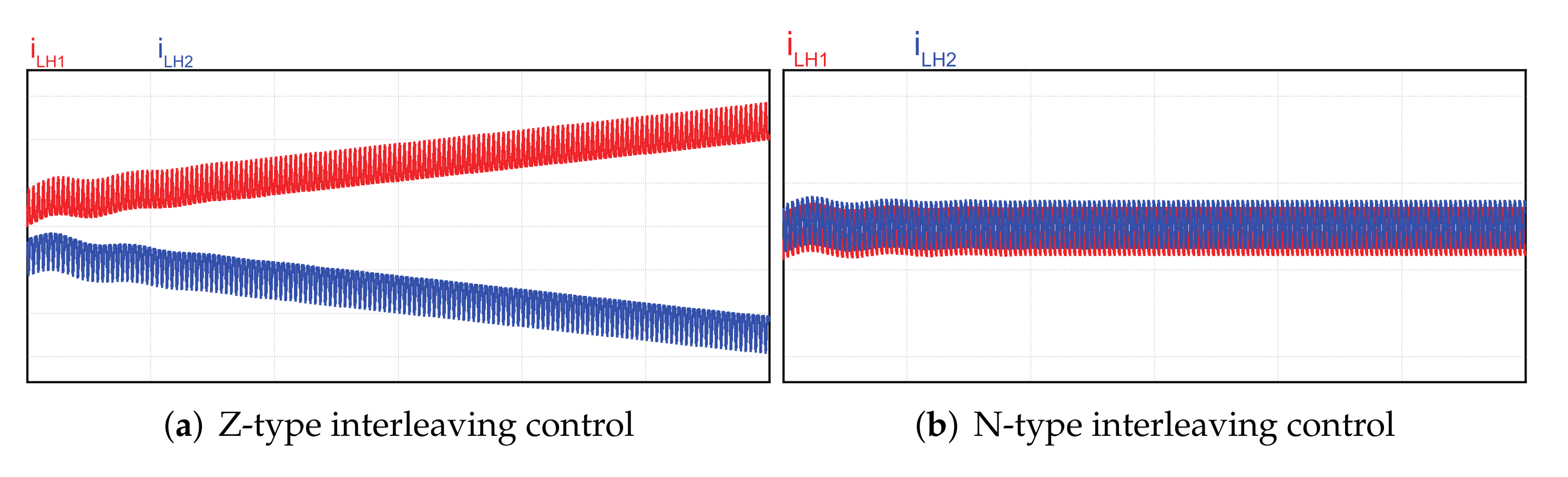
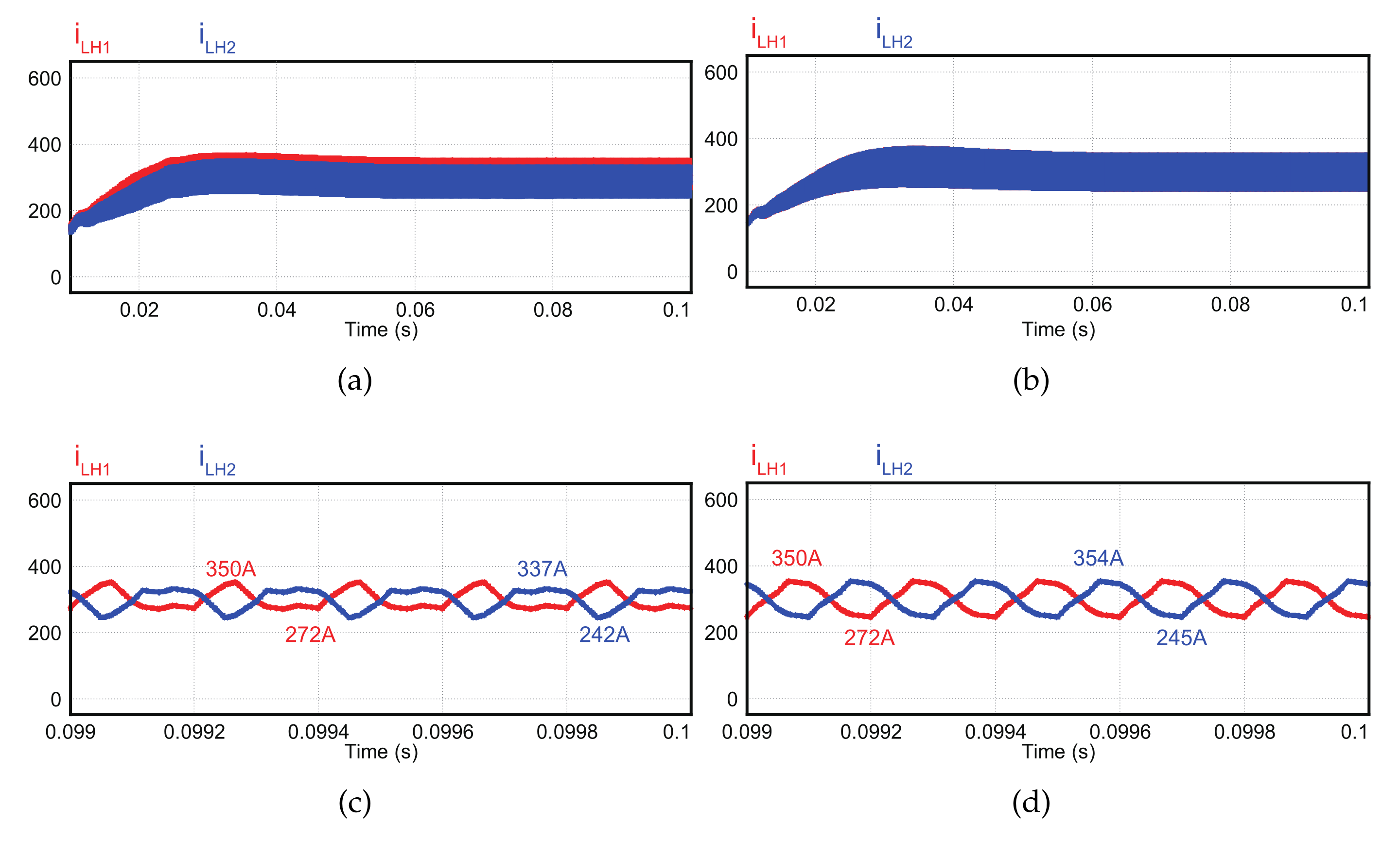
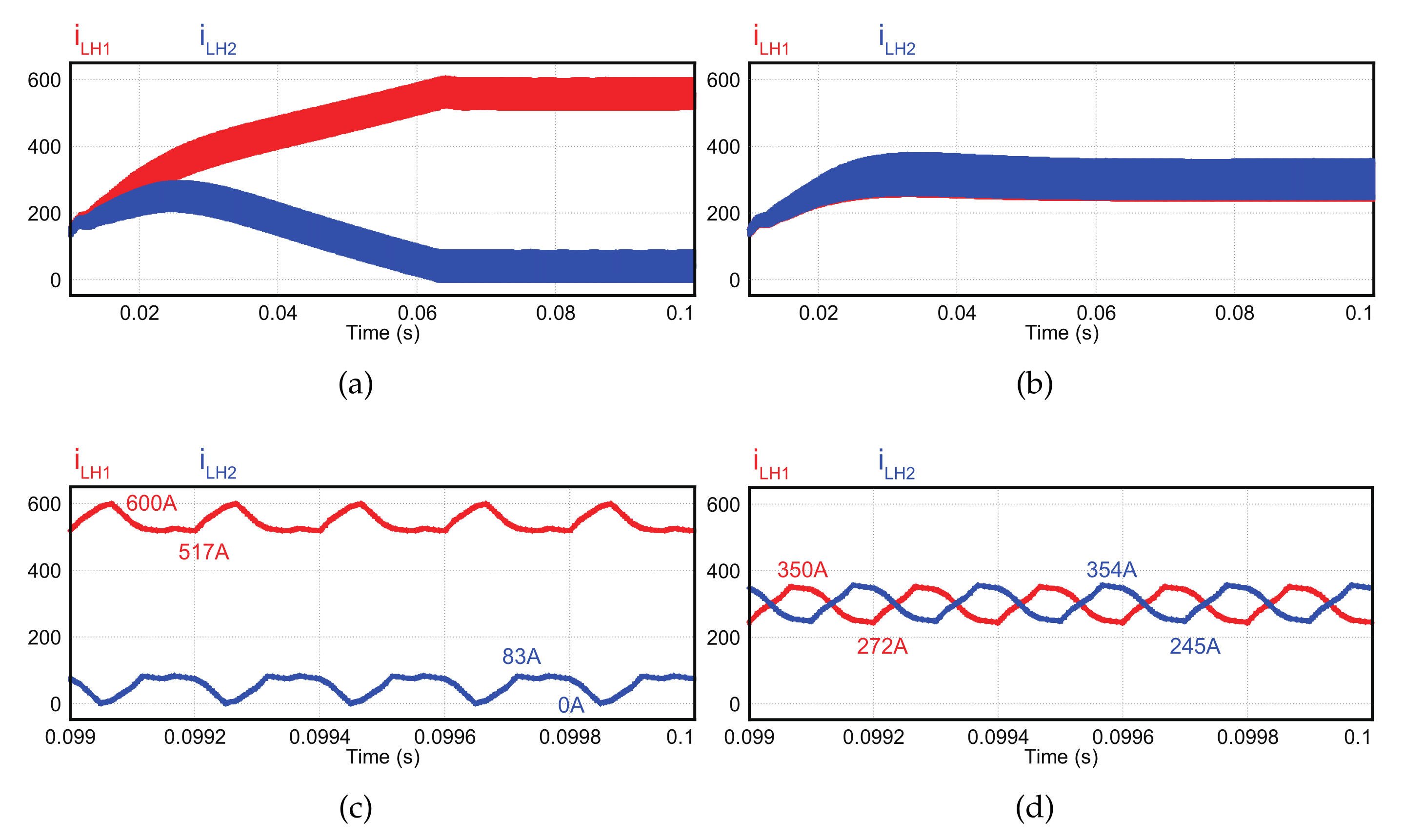
3.3. Current Imbalance with Z-Type Interleaving by the Capacitor Voltage

The two interleaving methods differ in terms of control as well. First, the Z-type interleaving method cannot evenly drive module currents with open loop drive. Open loop drive means that the current or voltage of the converter have no feedback signals. This implies that, in the absence of external disturbance, two module currents must be the same under same duty. However, the inductor current imbalance occurs in the Z-type interleaving control, so the inductor current is concentrated in the inductor of any one module. so that the electric power is concentrated in one module. This results in higher energy losses and heat generation. Furthermore, when the system operates at more than half the rated load, the excess power over the rated power flows on one side only. This can result in module destruction. Figure 12 illustrates the inductor current waveform for each interleaving method. In the Z-type interleaving open loop drive, the electric power is not evenly distributed to the modules, and the inductor current is concentrated in module 1. On the other hand, it can be observed that imbalance does not occur in an N-type interleaving open loop drive.
The inductor current imbalance occurs due to the different voltages applied to the inductors. To describe this phenomenon, Figure 13 illustrates the high-side and low-side capacitor voltages v F C H and v F C L , inductor voltages v L H 1 and v L H 2 applied to the high-side inductor of each module; and a high-side inductor current of module 1 i L H 1 with Z-type interleaving under an open loop drive.
States 1–8 in Figure 13 are defined according to the switching behavior of the Z-type interleaving method. As described above, interleaving control of a module of two or more phases generates a circulating current owing to differential voltage. The differential voltages between two high-side and two low-side inductors are generated by the voltages of the high-side and low-side capacitors, respectively. However, the capacitors repeatedly charge and discharge according to the switching operation, so the potential of capacitors continuously varies. The high-side inductor voltage of module 1 is positive in states 1, 2, 3, and 7 and negative in states 4, 5, 6, and 8. During states 3, 6, 7, and 8, the current imbalance does not occur because the same voltage is applied across the high-side inductors in both modules 1 and 2. In states 1 and 2, inductor current of module 1 is more increased where the voltage of the high-side capacitor is relatively high, and for states 4 and 5, the inductor current of module 1 is less decreased where the voltage of the high-side capacitor is relatively low. As a result, the current of the high-side inductor of module 1 gradually increases as more positive and less negative voltages are repeatedly applied. This is opposite to the scenario of the high-side inductor of module 2, the inductor current of module 2 is increased by a relatively low voltage, and inductor current of module 2 is decreased by a relatively high voltage. Therefore, the current of module 2 decreases gradually with repeated charging and discharging cycles. The more the cycle is repeated, the more severe the current imbalance. In contrast, the N-type interleaving method does not cause a current imbalance. Figure 14 illustrates the states according to the switching operation in the N-type interleaving method.
In Z-type interleaving control, the voltages of the high-side capacitor in the states 1 and 2 for the module 1 inductor are different from those in states 4 and 5. In contrast, the current imbalance does not occur during N-type interleaving control because the voltages of the high-side capacitor states 1, 2, and 3 are equal to those in the states 5, 6, and 7.
As a result, in open loop (non-feedback) drive, the Z-type interleaving method leads to current imbalance. Hence, it is essential to control the closed loop with a current controller in each module with the Z-type interleaving. In contrast, with the N-type interleaving method, a relatively simple control method with low computation requirements, such as an open loop drive or closed loop current control, may be used. This was verified by the simulation described in Section 4.

4. Simulation

In this section, to compare and analyze the effects of the interleaving methods of the two-phase parallel TLBC, the circulating current and filter capacitor voltage and current for each interleaving method are compared. The current imbalance is also investigated for each control method. Table 3 presents the parameters used in the simulation. Two converter modules with an input voltage of 1000 V and an output voltage of 1500 V were operated under a load of 300 kW each (totally 600 kW).
Figure 15 illustrates the circuit diagram used for the simulation, where the circuit consists of two-phase parallel TLBC with added low-side inductors connected to the neutral point of the filter capacitors. Closed loop control was simulated to measure and control the output voltage and inductor current, and the master–slave method was applied as parallel control. The master controller transmits phase information for interleaving operations to each slave controller and performs imbalance compensation control to match the voltages across the high-side and low-side capacitors. Figure 16 presents the circulating current i D M for two types of the interleaving method. As shown in Figure 16, the ripple of the circulating current for Z-type and N-type interleaving control is approximately 70 A and 100 A, respectively. This indicates that the ripple of circulating current is larger in N-type control, and, accordingly, the effective value and harmonic component are also larger in this case.
Now, consider the filter capacitor voltage and current for Z-type and N-type interleaving methods. Figure 17 shows the high-side filter capacitor current i F C H and FFT analysis for each interleaving method. As previously discussed, the filter capacitor current ripple in Z-type interleaving is larger than that in N-type interleaving. Moreover, the rms value of the capacitor current is in Z-type interleaving is larger (93 A) than that in N-type interleaving (72 A). The results for the N-type interleaving method are affected increasing the frequency of the fundamental wave component of harmonics to a double frequency. Moreover, the magnitude of (major) harmonic component of N-type interleaving is reduced. These are significantly lower than the fundamental component without interleaving as well as the fundamental component of the Z-type interleaving method.
The interleaving method affects also the capacitor voltage as well as capacitor current. Figure 18 presents the capacitor voltage waveform v F C H 1 for each interleaving method.
Figure 18 reveals that the voltage ripple of a filter capacitor in Z-type interleaving control is larger than that in N-type interleaving, and that the ripple cycle is two times as long in the former than in the latter. The simulation analyses described earlier used two current controllers for each module in a voltage controller (see Figure 19a). However, for N-type interleaving, as illustrated in Figure 19b, the average current of the two modules can be controlled using a current controller. However, even in this case, Z-type interleaving causes current imbalance, as discussed in Section 3.3.
First, as shown in Figure 19a, when single current controller is used per module, the current is effectively divided for both interleaving methods without current imbalance (Figure 20).
However, the different current response may be appeared when only one current controller is used. Figure 21 shows the current waveform for two-phase TLBC with single current controller for both interleaving methods. For the Z-type interleaving method, as illustrated in Figure 21, the inductor current is concentrated in one module, similar to the case of open loop drive. However, with the N-type interleaving method, the inductor currents are evenly distributed in each module.
The following table compares the performance of TLBC according to the interleaving method. According to each method, the rms current value of the filter capacitor ( i F C H r m s ) , the voltage ripple of the filter capacitor and whether the open-loop control is possible and the efficiency were compared. In comparison, good things are highlighted with green, and bad things are highlighted with red.
Efficiency analysis was also carried out by PSIM simulation, and ESR of passive devices and forward voltage of IGBT were considered. Efficiency analysis was performed and considered with the same ESR for inductor and capacitor. In this analysis, copper loss was only considered for module loss. The N-type interleaving method has more inductor loss than the Z-type interleaving method, but since the capacitor loss is reduced more than that, the efficiency is good as a result. As a result, Table 4 shows that the N-type interleaving method is better.

5. Conclusions

In this study, the effect of two interleaving methods on a two-phase parallel three-level bidirectional DC/DC converter was investigated. First, the current of the filter capacitor was formulated through a switching function. Furthermore, the current and voltage of the filter capacitor were investigated by analyzing the operating modes and switching status of switches depending on the interleaving method. In the case of Z-type interleaving control, there is a state in which the capacitor bears all of the output current. Thus, the ripple of the current and voltage of the filter capacitor increases. Furthermore, the inductor current imbalance occurs between two modules due to the difference in the inductor voltages during the charging and discharging states of the high-side and low-side inductors under open loop drive. In conclusion, the N-type interleaving method has more merits to control parallel TLBC because it is superior to the Z-type interleaving method in terms of capacitor of life, EMI noise, and convenience of filter capacitor control. This has been verified by PSIM simulations, which will then be pursued through parallel control techniques for two or more phases of TLBC and other topologies.

Author Contributions

H.-I.K. conceptualized, wrote original draft preparation, and did simulations. S.-H.K. assisted in visualizing the data. H.-W.K. and S.-W.B. conceived the idea and wrote the paper. K.-Y.C. and G.-D.K. assisted in idea development and paper writing. All authors have read and agreed to the published version of the manuscript.

Funding

The research was supported by a grant from the Academic Research Program of Korea National University of Transportation in 2021. This research was supported by a grant from “Material parts technology development project” of Korea Evaluation Institute of Industrial Technology (KEIT) of the republic of Korea (No. 20001101).

Conflicts of Interest

The authors declare no conflict of interest.

References

  1. Chen, X.L.; Liang, D.Q.; Zhang, W.D. Braking energy recovery for electric traction based on super-capacitor and bidirectional dc-dc converter. In Proceedings of the 7th International Power Electronics and Motion Control Conference, Harbin, China, 2–5 June 2012; Volume 2, pp. 879–883. [Google Scholar] [CrossRef]
  2. Lianfu, T.; Lixin, W. Research on the integrated braking energy recovery strategy based on super-capacitor energy storage. In Proceedings of the 2017 International Conference on Smart Grid and Electrical Automation (ICSGEA), Changsha, China, 27–28 May 2017; pp. 175–178. [Google Scholar] [CrossRef]
  3. Wang, F.; Zhuo, F.; Wang, X.; Guo, H.; Wang, Z. Bi-directional interleaving dc/dc converter used in dual voltage system for vehicle. In Proceedings of the 2009 IEEE 6th International Power Electronics and Motion Control Conference, Wuhan, China, 17–20 May 2009; pp. 1335–1339. [Google Scholar] [CrossRef]
  4. Meleshin, V.; Zhiklenkov, D.; Ganshin, A. Efficient three-level boost converter for various applications. In Proceedings of the 2012 15th International Power Electronics and Motion Control Conference (EPE/PEMC), Novi Sad, Serbia, 4–6 September 2012; pp. DS1e.9-1–DS1e.9-8. [Google Scholar] [CrossRef]
  5. Kan, Z.; Li, P.; Yuan, R.; Zhang, C. Interleaved three-level bi-directional dc-dc converter and power flow control. In Proceedings of the 2018 3rd International Conference on Intelligent Green Building and Smart Grid (IGBSG), Yilan, Taiwan, 22–25 April 2018; pp. 1–4. [Google Scholar]
  6. Dusmez, S.; Hasanzadeh, A.; Khaligh, A. Comparative analysis of bidirectional three-level dc–dc converter for automotive applications. IEEE Trans. Ind. Electron. 2015, 62, 3305–3315. [Google Scholar] [CrossRef]
  7. Mei, Y.; Li, X.; Qi, Y. A model predictive control method for three-level bi-directional dc-dc converter in renewable generation system. In Proceedings of the 2015 18th International Conference on Electrical Machines and Systems (ICEMS), Pattaya, Thailand, 25–28 October 2015; pp. 417–421. [Google Scholar] [CrossRef]
  8. Haddad, K. Three level dc-dc converters as efficient interface in two stage PV power systems. In Proceedings of the 2012 IEEE Energytech, Cleveland, OH, USA, 29–31 May 2012; pp. 1–6. [Google Scholar] [CrossRef]
  9. Yao, G.; Hu, L.; Liu, Y.; Chen, A.; He, X. Interleaved three-level boost converter with zero diode reverse-recovery loss. In Proceedings of the Nineteenth Annual IEEE Applied Power Electronics Conference and Exposition (APEC ’04), Anaheim, CA, USA, 22–26 February 2004; Volume 2, pp. 1090–1095. [Google Scholar] [CrossRef]
  10. Bilgin, M.S.; Poyrazoglu, G.; Aktem, M.; Er, E. DC-link capacitor lifetime under various operating conditions. In Proceedings of the 2019 IEEE 13th International Conference on Compatibility, Power Electronics and Power Engineering (CPE-POWERENG), Sonderborg, Denmark, 23–25 April 2019; pp. 1–6. [Google Scholar] [CrossRef]
  11. Basu, S.; Undeland, T.M. Voltage and current ripple considerations for improving lifetime of ultra-capacitors used for energy buffer applications at converter inputs. In Proceedings of the 2010 Twenty-Fifth Annual IEEE Applied Power Electronics Conference and Exposition (APEC), Palm Springs, CA, USA, 21–25 February 2010; pp. 244–247. [Google Scholar] [CrossRef]
  12. Kim, Y.J.; Kim, S.M.; Lee, K.B. A switching method for improving lifetime of dc-link capacitors in hybrid ANPC inverters. In Proceedings of the 2019 IEEE Student Conference on Electric Machines and Systems (SCEMS 2019), Busan, Korea, 1–3 November 2019; pp. 1–4. [Google Scholar] [CrossRef]
  13. Zeng, Y.; Li, H.; Zhang, Z.; Zheng, T.Q.; Shang, Z.; Qiu, Z.; Yuan, L.; Ding, Y. A parallel-resonant isolated bidirectional dc-dc converter with low current ripple for battery storage systems. In Proceedings of the 2019 IEEE Energy Conversion Congress and Exposition (ECCE), Baltimore, MD, USA, 29 September–3 October 2019; pp. 5548–5553. [Google Scholar] [CrossRef]
  14. ElMenshawy, M.; Massoud, A. Multimodule dc-dc converters for high-voltage high-power renewable energy sources. In Proceedings of the 2019 2nd International Conference on Smart Grid and Renewable Energy (SGRE), Doha, Qatar, 19–21 November 2019; pp. 1–6. [Google Scholar] [CrossRef]
  15. Shanthi, N.; Deepalaxmi, R. Performance analysis of three level interleaved boost converter with coupled inductor. In Proceedings of the 2019 Fifth International Conference on Electrical Energy Systems (ICEES), Chennai, India, 21–22 February 2019; pp. 1–6. [Google Scholar] [CrossRef]
  16. Itoh, J.i.; Abe, T. Circulation current reduction for a motor simulator system using a power converter with a common mode transformer. In Proceedings of the 2009 IEEE 6th International Power Electronics and Motion Control Conference, Wuhan, China, 17–20 May 2009; pp. 1662–1667. [Google Scholar] [CrossRef]
  17. Liu, L.; Liu, Z.; Chen, Q. Research and simulation of circulation current control for grid tied inverters connected in parallel. In Proceedings of the 2016 Chinese Control and Decision Conference (CCDC), Yinchuan, China, 28–30 May 2016; pp. 6036–6041. [Google Scholar] [CrossRef]
  18. Lu, S.; Mu, M.; Jiao, Y.; Lee, F.C.; Zhao, Z. Coupled inductors in interleaved multiphase three-level dc-dc converter for high-power applications. IEEE Trans. Power Electron. 2016, 31, 120–134. [Google Scholar] [CrossRef]
  19. Lee, J.-Y.; Kim, J.S. A study on the reliability of a hot-swap applied DVR power supply using fault tree analysis. In Proceedings of the Korean Power Electronics Society Conference, Sono Belle Byeonsan, Buan-Gun Jeollabuk-Do, Korea, 6–8 July 2021; pp. 412–413. [Google Scholar]
  20. Lee, K.M.; Baek, S.W.; Kim, H.W.; Cho, K.Y.; Kang, J.W. 3-level boost converter having lower inductor for interleaving operation. Trans. Korean Inst. Electron. 2021, 26, 96–105. [Google Scholar]
  21. Wang, R.R. High Power Density and High Temperature Converter Design for Transportation Applications; Virginia Polytechnic Institute and State University: Blacksburg, VA, USA, 2012. [Google Scholar]
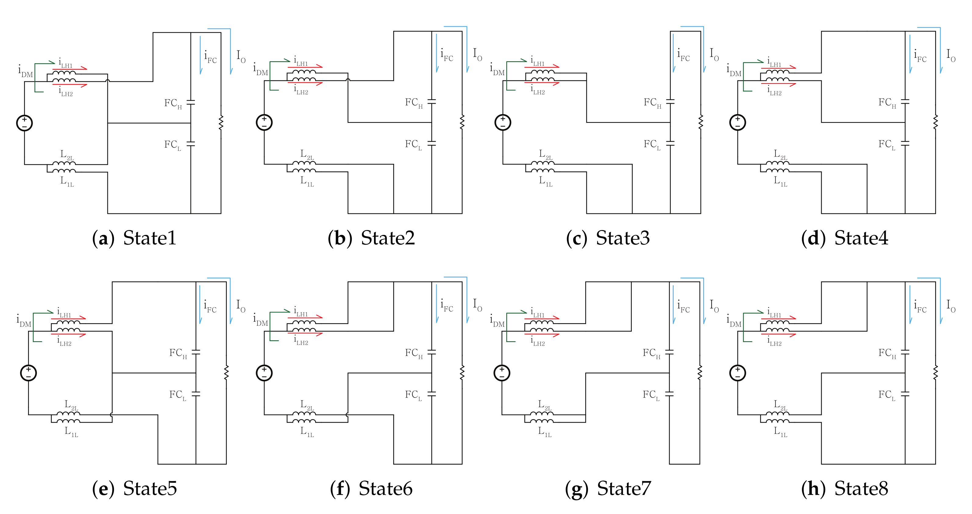
Figure 1. Single-module TLBC circuit diagram.
Energies 15 00006 g001
Figure 2. Circuit diagram of two-phase parallel TLBC.
Energies 15 00006 g002
Figure 3. Switching operation according to interleaving methods.
Energies 15 00006 g003
Figure 4. (a) Circuit diagram of a two-phase parallel TLBC; (b) equivalent circuit diagram of a TLBC with interleaving control.
Energies 15 00006 g004
Figure 5. Equivalent circuit for the analysis of circulating current.
Energies 15 00006 g005
Figure 6. (a) Circulating current generated during Z-type interleaving; (b) circulating current generated during N-type interleaving.
Energies 15 00006 g006
Figure 7. Inductor Currents for interleaving methods.
Energies 15 00006 g007
Figure 8. Operating modes and switching status for Z-type interleaving.
Energies 15 00006 g008
Figure 9. Circuit diagram according to the N-type interleaving switching operation.
Energies 15 00006 g009
Figure 10. Capacitor current waveforms.
Energies 15 00006 g010
Figure 11. High-side capacitor voltage waveforms.
Energies 15 00006 g011
Figure 12. Current response in two modules for open loop drive.
Energies 15 00006 g012
Figure 13. Voltage and current waveforms for Z-type interleaving with an open loop drive.
Energies 15 00006 g013
Figure 14. Waveforms observed when N-type interleaving is performed on a TLBC as an open loop.
Energies 15 00006 g014
Figure 15. Simulation analysis circuit diagram.
Energies 15 00006 g015
Figure 16. Comparison of circulating current by the interleaving methods.
Energies 15 00006 g016
Figure 17. (a) Capacitor current for Z-type interleaving; (b) capacitor current for N-type interleaving.
Energies 15 00006 g017
Figure 18. (a) Capacitor voltage for Z-type interleaving; (b) capacitor voltage for N-type interleaving.
Energies 15 00006 g018
Figure 19. (a) TLBC with two current controllers; (b) TLBC with single current controllers.
Energies 15 00006 g019
Figure 20. (a) Inductor currents for Z-type interleaving with two current controller; (b) inductor currents for N-type interleaving with two current controller; (c) enlarged (a); (d) enlarged (b).
Energies 15 00006 g020
Figure 21. (a) current imbalance occurring during Z-type interleaving control in single current controller system; (b) current unbalance that does not occur during N-type interleaving control in a single current controller system; (c) enlarged (a); (d) enlarged (b).
Energies 15 00006 g021
Table 1. High-side capacitor current for eight operating states of a Z-type interleaving method.
State i FCH
1 i L H 2 I o
2 i L H 2 I o
3 I o
4 i L H 1 I o
5 i L H 1 I o
6 i L H 1 + i L H 2 I o
7 i L H 1 + i L H 2 I o
8 i L H 1 + i L H 2 I o
Table 2. High-side capacitor current for eight operating states of the N-type interleaving method.
State i FCH
1 i L H 2 I o
2 i L H 2 I o
3 i L H 2 I o
4 i L H 1 + i L H 2 I o
5 i L H 1 I o
6 i L H 1 I o
7 i L H 1 I o
8 i L H 1 + i L H 2 I o
Table 3. System parameter.
ParameterValueUnit
Rated Power300kW
Input Voltage1000V
Output Voltage1500V
Load Resistor3.75 Ω
Inductance ( L H , L L )0.25mH
Capacitance ( C H , C L )900uF
Switching Frequency5kHz
Number of Modules2-
Table 4. Performance comparison table according to the interleaving method.
Non-InterleavingZ-typeN-typeUnit
InterleavingInterleaving
ine i L H r m s 323325328A
i F C H r m s 1409372A
Δ v F C H 1594V
open loop drivepossibleimpossiblepossible
Efficiency91.592.292.7%
ine : better
: worse
Publisher’s Note: MDPI stays neutral with regard to jurisdictional claims in published maps and institutional affiliations.

