Article

Design of an Effective State of Charge Estimation Method for a Lithium-Ion Battery Pack Using Extended Kalman Filter and Artificial Neural Network

1
Department of Electrical Engineering, Changwon National University, Changwon 51140, Korea
2
Institute of Mechatronics, Changwon National University, Changwon 51140, Korea
3
Distributed Power System Research Center, Korea Electrotechnology Research Institute, Changwon 51543, Korea
4
Battery Solution Co., Ltd., Jeonnam 58324, Korea
5
IES Co., Ltd., Busan 46744, Korea
*
Author to whom correspondence should be addressed.
Energies 2021, 14(9), 2634; https://doi.org/10.3390/en14092634
Submission received: 6 April 2021 / Revised: 27 April 2021 / Accepted: 27 April 2021 / Published: 4 May 2021
(This article belongs to the Special Issue Power Electronics and Energy Management for Battery Storage Systems)

Abstract

:
Currently, Lithium-ion batteries (LiB) are widely applied in energy storage devices in smart grids and electric vehicles. The state of charge (SOC) is an indication of the available battery capacity, and is one of the most important factors that should be monitored to optimize LiB’s performance and improve its lifetime. However, because the SOC relies on many nonlinear factors, it is difficult to estimate accurately. This paper presented the design of an effective SOC estimation method for a LiB pack Battery Management System (BMS) based on Kalman Filter (KF) and Artificial Neural Network (ANN). First, considering the configuration and specifications of the BMS and LiB pack, an ANN was constructed for the SOC estimation, and then the ANN was trained and tested using the Google TensorFlow open-source library. An SOC estimation model based on the extended KF (EKF) and a Thevenin battery model was developed. Then, we proposed a combined mode EKF-ANN that integrates the estimation of the EKF into the ANN. Both methods were evaluated through experiments conducted on a real LiB pack. As a result, the ANN and KF methods showed maximum errors of 2.6% and 2.8%, but the EKF-ANN method showed better performance with less than 1% error.

1. Introduction

Energy storage systems are emerging as the biggest concern for modern smart grids and electric vehicles (EV), and the lithium-ion battery (LiB) technology is an efficient solution for energy storage applications with the advantages of long cycle life, large capacity and no memory effect. Already commercialized and matured for consumer electronic applications, the LiB is being positioning itself as a leading technology platform for plug-in hybrid electric vehicles (PHEVs) and all EVs [1,2]. It is also widely used in large facilities to support energy storage [3], load-leveling and peak shaving in the power grid [4], frequency regulation [5], and to reduce network load and capacity payments [6] in the smart grids.
In order for the LiBs to work as expected, a battery management system (BMS) must be designed for tracking and controlling the current level of battery energy. The BMS is defined as an electronic equipment that manages a rechargeable battery (single cell or battery pack). The main functions of the BMS are to monitor, compute, communicate, protect, and optimize [7]. At this point, the estimate of state of charge (SOC) is one of the critical functions in the BMS. The SOC is defined as the percentage of the available capacity to the rated capacity of the battery, and many issues with the LiB, such as capacity degradation, increased maintenance costs, rapid aging, serious equipment failures, and even dangerous accidents, are related to incorrect SOC estimates [8]. Therefore, an accurate estimation of the SOC is very important for optimizing battery performance, including extending battery life and preventing permanent damage to the batteries.
In general, the battery SOC nonlinearly depends on several factors including current, voltage, temperature, and battery aging [9]. Therefore, an accurate estimate of the SOC is quite complicated. Various techniques have been presented to estimate the SOC of a battery cell or a battery pack. Key technologies include discharge tests, open-circuit voltage measurement, Coulomb counting, inherent resistance measurement, and intelligent SOC estimation methods [10,11]. Intelligent computation techniques such as artificial neural network (ANN) and Kalman filter (KF) have been developed for EV applications [12,13,14,15,16]. Compared to other techniques, they have several advantages such as high accuracy, real-time calculation, simple current and voltage measurements. Specifically, these techniques are highly adaptable to the dynamic behaviors of batteries due to their self-learning ability. However, there are still some issues that need to be studied. Applying KF requires accurate battery modeling, and important factors such as temperature and SOC that may affect the internal parameters of the battery model are not yet considered. Using an ANN requires a large amount of training data that can lead to a large dimension and high computation of the network when implemented in a BMS. Therefore, it is necessary to design a practical BMS to properly analyze and evaluate the operational characteristics of the SOC estimation methods.
In this paper, an effective SOC estimation method was designed and implemented in a smart BMS for a LiB pack based on the extended KF (EKF) and ANN. First, the structure and specifications of the smart BMS and LiB pack were summarized, and the design process of the ANN was described in detail. The ANN was then trained and tested for SOC estimation using real battery data sets. Next, we developed an SOC estimation algorithm based on the EKF and a Thevenin battery model. Finally, we proposed a combination model of EKF and ANN (EKF-ANN) to compensate for the shortcomings of the above two methods. To evaluate the effectiveness of the SOC estimation method, the proposed methods were experimentally verified and compared with each other. As a result, the proposed ANN and EKF methods showed an error of 2.6% and 2.8%, respectively, and the SOC estimation error when using the EKF-ANN was significantly improved to less than 1%. The results show that the proposed SOC estimation method satisfies the requirements of the BMS for LiB packs.

2. Review of SOC Estimation Methods

An accurate estimate of the SOC plays an important role in a credible BMS, but the SOC cannot be measured directly. The SOC is associated with direct measurements such as current, voltage, temperature, and it can be extracted based on intrinsic relations or control theory of the battery. Many techniques have been proposed to estimate the battery SOC. In this section, we discuss some popular SOC estimation methods and compare them with each other.

2.1. Open Circuit Voltage Method

This method calculates the SOC or the remaining capacity of the battery based on the measured open-circuit voltage (OCV). Each battery has a corresponding curve between the SOC and OCV, from which one can determine the other. However, in order to get a stable voltage, the battery must be rested for a long time under no load. Moreover, since the OCV-SOC curve is sensitive to various temperatures and discharge rates, the method is only effective in estimating the SOC at the early and end stages of the charging and discharging process after the battery has been disconnected from the load for a long time [17,18].

2.2. Coulomb Counting Method

Coulomb counting, which is also called Ampare-hour (Ah) counting, is the most common technique for estimating the SOC based on the integration on time of the charge and discharge current values. However, the initial SOC is difficult to determine at the starting state. Even though we can gain the SOC from the record of the BMS or OCV look-up table, but the accuracy is hard to ensure [19]. Additionally, the SOC calculation is based only on the measurement of current without considering the measurement noise. Over time, errors will be accumulated due to the integration factor, and this is the reason why this method is prone to errors.

2.3. Impedance-Based Method

There is a dependency between the SOC and the impedance of a battery, and thus the SOC can be considered a function of battery impedance change [20]. However, the impedance varies significantly with the aging status of a battery; thus, this technology is no longer a good indicator for the SOC. Furthermore, the sensitivity of the battery impedance on the temperature is very high; thereby a high accuracy of SOC estimation is impossible to maintain for batteries in EVs due to quick temperature change during the driving process.

2.4. Kalman Filter-Based Method

The KF is a method for determining the internal states of any dynamic process, in which the mean of the squared error is minimized. Its target is to obtain accurate information from inaccurate data. This method can be utilized to calculate the SOC in real-time by using the terminal current and voltage measurements [21,22,23]. It is suitable for the SOC estimation of EVs in which the battery current is unstable [24]. However, it has high demands for the battery modelling and computational capability [25,26].

2.5. Artificial Neural Network-Based Method

The ANN is an intelligent technology, which has a strong self-learning and high adaptability, and this technique is very useful for researching complex nonlinear system models. For the SOC estimation, the ANN is able to be applied in all battery systems without the information of cell internal structure, as long as the battery dataset for training the network is available [27,28]. Also, the ANN has the ability to estimate the SOC without the initial SOC.

2.6. Fuzzy Logic-Based Method

This method is based on simulating the fuzzy thinking of a human being using the fuzzy logic based on a large number of test curves, experience and reliable fuzzy logic theories, and finally to perform the SOC estimation [29]. It requires a complete understanding of the battery itself and relatively large computations. However, the battery parameters significantly vary with the battery lifetime, and so the SOC estimation may not be accurate enough. It is only suitable for static battery characteristics and practically inapplicable for LiBs in the EVs [30].
In this paper, we decided to develop an effective SOC estimation method based on the ANN and KF.

3. Design of SOC Estimation Methods for a Smart BMS

3.1. Configuration of the Smart BMS and LiB Pack

A BMS is a device including hardware and software which controls the operating conditions of the battery to extend battery life, ensure safety, and accurately predict the various states of the battery. To ensure this, the BMS has several functions to control and monitor the battery states at various battery cells, battery modules, and battery pack levels. The estimation of the SOC is a core function in a BMS, but it is still a challenge to accurately estimate in online-real time, as battery characteristics change with the degree of aging and strong nonlinear and complex electrochemical reactions of the battery. The SOC can be estimated by continuously measuring terminal voltage, current and temperature of the battery. For a battery system in EVs and smart grids, the current trend is the design of a smart BMS, which includes researches in the field of artificial intelligence (AI) utilized for the battery SOC estimation. In large battery pack applications, the predictability and adaptability of BMS are especially important. In this study, in order to verify the performance of the SOC estimation methods through experiments, we developed a smart BMS module based on the master and slave topology design for the LiB pack as shown in Figure 1.
The LiB pack consisted of 3 module units connected in series, and each module unit consisted of 36 cells with a 9S4P configuration, meaning 9 cells in series and 4 cells in parallel. There are 3 slave microcontroller unit (MCU) boards to manage the module units. The main MCU board, which is the master, coordinates two-way communication between the master and the slave and executes battery management actions. The detailed specifications of the smart BMS and LiB pack are described in Table 1. We will develop SOC estimation methods with an error target of 3% as shown in Table 2.

3.2. SOC Estimation Method Using an ANN

3.2.1. Design Process for the ANN

An ANN is a computational model constructed by a set of individual processing units, which are called the artificial neurons. These neurons are interconnected by weights. The ANN is a universal approximator that is able to model any nonlinear function with the desired precision [33]. The network is configured in layers, with the input layer receiving inputs and the output layer generating outputs. The middle layers, called the hidden layers, have no connection with the outside. The neurons are responsible for connecting each layer, thereby they are the central component of the ANN. The basic configuration of a neuron in the network is described in Figure 2. The vector of the input signals is denoted by X = [ x 1 , x 2 , x 3 , , x n ] , n N , the neuron weights by W = [ W 1 , W 2 , W 3 , , W n ] , n e t is the multiplication response of weights with the input signals, b 1 is an external parameter called as the bias, f is the activation function, and y m is the output signal of the neuron.
Table 3 shows the design process and design factors of an ANN for the SOC estimation. It starts from collecting and pre-processing the data, then designing the neural network in terms of network topology, configuration, activation function, loss function and metrics, loss optimizer, and learning rate. Finally, the training and validation of the network are implemented.

3.2.2. Design of the ANN for the SOC Estimation

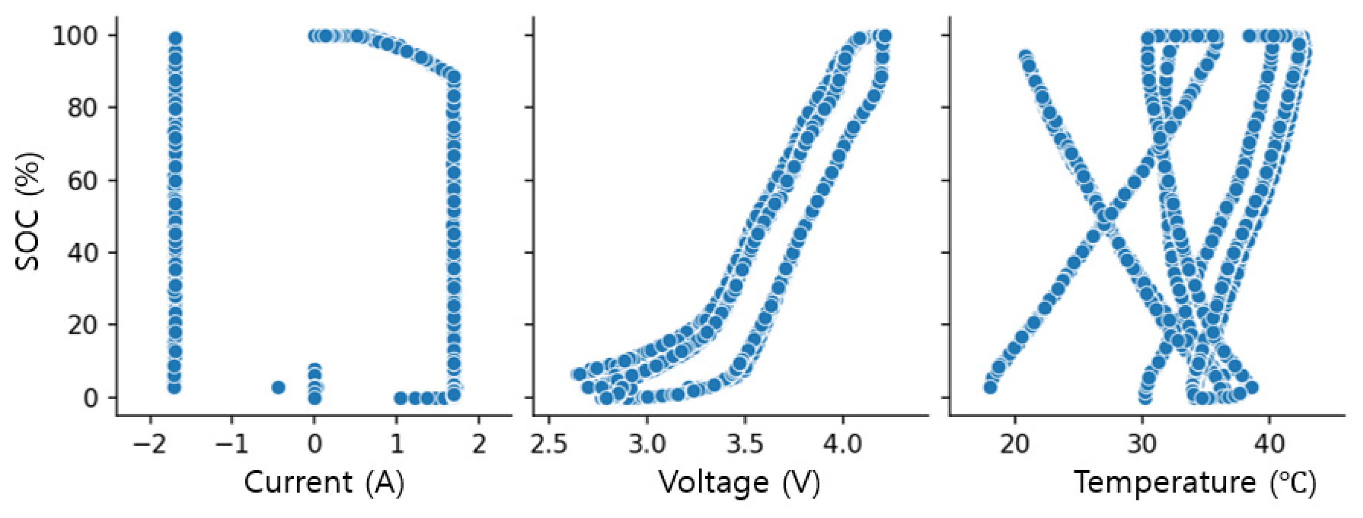
The historical battery dataset was collected from the designed LiB pack by the company Battery Solution Co., Ltd. in South Korea. The dataset consists of the test time in seconds, the pack current in ampere, the pack terminal voltage in volts, the pack temperature, and the cumulative charge/discharge capacity of the battery pack in ampere-hour. The LiB pack was tested under 0–100% of the SOC condition for 20 cycles at room temperature. The data was collected with a sampling time of 1 s. The battery pack was charged and discharged with a constant current of 1.7 A (0.5 C rate). The battery charge and discharge processes correspond to the plus (+) and minus (−) signs of the current. The temperature was measured at the center of the battery pack by a thermal sensor with an accuracy of ±0.5 °C, and the temperature range was from 19 °C to 42 °C. From the battery pack dataset, the average values of voltage and current in one cell were calculated. The cell voltage range was from 2.6 V to 4.2 V. The actual SOC was also calculated offline by the integration on time of current to use for training and testing the ANN model. The dataset must be processed to obtain a satisfactory ANN, all trash data was deleted. The ANN was trained to estimate the SOC of one cell.
The next step was to design the network topology for the ANN, and the Multi-Layer Perception (MLP) network was selected. The inputs of the network were the current, voltage, and temperature, and the output was the battery SOC. Figure 3 describes the relationships between the inputs and outputs of the designed ANN. The SOC has strong and nonlinear relationships with the voltage and temperature, which can be expressed as exponential functions. Thus, the nonlinear activation functions including hyperbolic tangent (tanh) and logistic (sigmoid) were considered for the ANN. The learning rate, α, is an amount by which the weights are updated during the training process. In the proposed network, the learning rate was set at 0.001.
After tuning the parameters and testing several configurations of the network, the most suitable specifications for the ANN are described in Table 4.
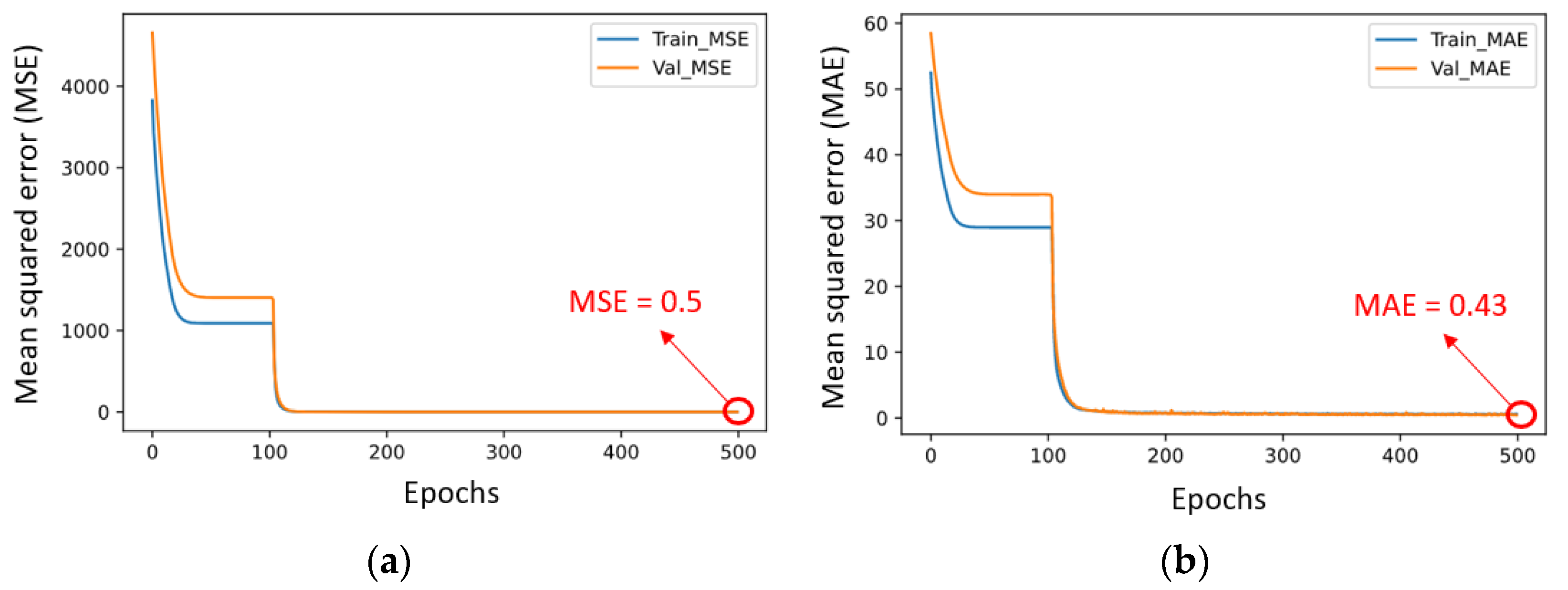
The battery dataset contained approximately 250,000 samples, corresponding to the data measured at each sampling time. Each sample consisted of three input variables (battery voltage, current and temperature) and the actual SOC. Before training the network, the dataset was normalized and randomized to separate them into three sets: training, validation, and testing. The data in each set were different from each other and split evenly into three input variables. The amount of sample data for the training, validation, and testing were 80%, 10%, and 10% of the total samples, respectively. In this study, the ANN was designed, trained, and tested by using the Keras framework in the TensorFlow open-source library of Google. The ANN was trained during 500 epochs. As a result, the training performance achieved an MSE of approximately 0.5 and an MAE of approximately 0.43 in the final epoch as shown in Figure 4. From the epoch of 150, the training losses almost match the validating losses.
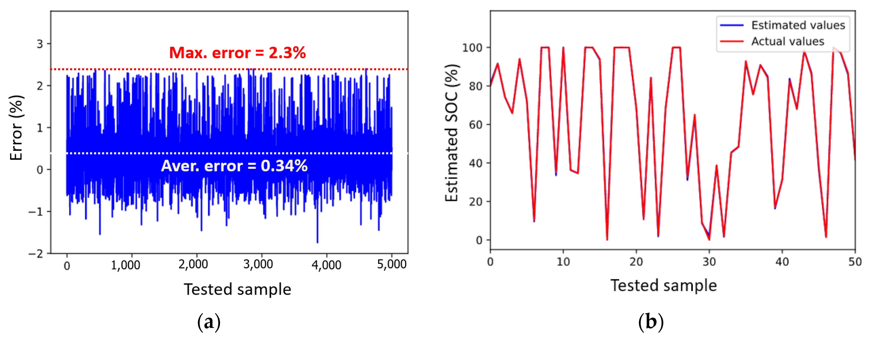
After the training process, the model testing was performed to compare the estimated results and the actual results as described in Figure 5. The trained ANN was tested randomly with 5,000 samples, and the maximum and average errors of the estimated SOC were 2.3% and 0.34%, respectively. This result is satisfied with the target of SOC estimation.
When the training process was completed, the weights and bias of the network were saved and exported as matrices to implement the SOC estimation function in the BMS for experiments.

3.3. SOC Estimation Method Using the EKF

In 1960, Kalman successfully introduced the state space into filter theory and first proposed the KF. Basically, the standard KF is only appropriate for linear dynamic systems to obtain the best and unbiased estimate of the state variables. However, the battery is a non-linear system; thus, it needs to be linearized and approximated to a linear system. At this point, the system states can be estimated by the KF. This method is called the extended Kalman Filter (EKF) [34]. To implement the EKF, a battery model is first developed to define internal state variables, state-space equations to build the mathematical model. Moreover, based on the external variables, such as terminal voltage, current, and temperature, the battery model is able to determine the internal state variables such as the internal resistance, electromotive force, capacitance and SOC.

3.3.1. Battery Model for the LiB

In this study, the Thevenin model was chosen as a LiB model. This model type has good performance and can accurately simulate the dynamic characteristics of the LiB [35]. Figure 6 describes the equivalent circuit of the Thevenin battery model, which consists of an ideal source of voltage VOC (OCV), an internal resistance R0, a polarization resistance Rp, and a capacitor Cp. The terminal voltage and current of the battery are denoted by VL and IL, respectively. The voltage and current flowing through the branch RpCp are denoted by Vp and Ip, respectively.
Based on the Kirchhoff’s laws, the capacitor voltage variation, its current relationship and the characteristics of the Thevenin model can be expressed as follows:
V P · = I L C P V P R P C P
V L = V O C V P I L R 0
From Equations (1) and (2), where τ = R p C p is the time constant and Δ t is the sampling time, a discrete-time system for the VL and Vp is built as shown in the Equations (3) and (4).
V P ( k ) = exp ( Δ t τ ) × V P ( k 1 ) + ( 1 exp ( Δ t τ ) ) × I L ( k 1 ) R P ( k )
V L ( k ) = V O C ( k ) V P ( k ) I L ( k ) R 0 ( k )
The VOC, R0, Rp and Cp are nonlinear functions of the battery SOC [36], thus the Equations (3) and (4) can also be expressed as below.
V P ( k ) = exp ( Δ t τ ) × V P ( k 1 ) + ( 1 exp ( Δ t τ ) ) × I L ( k 1 ) R P ( S O C ( k ) )
V L ( k ) = V O C ( S O C ( k ) ) V P ( k ) I L ( k ) R 0 ( S O C ( k ) )
The SOC describes the relationship between the remaining and the maximum capacity available in the battery and can be described as Equation (7):
S O C ( k ) = S O C ( k 1 ) I L ( k ) × Δ t C a
where Ca is the nominal capacity of the battery, and the SOC(k − 1) is the priority SOC. By using the Equations (5)–(7), we can express the state equation for the nonlinear battery system as follows:
{ x k = A k 1 x k 1 + B k 1 u k 1 + w k 1 y k = C k x k + D k u k + v k
with, x k = [ V P ( k ) S O C ( k ) ] , A k = [ 1 0 0 exp ( Δ t τ ) ] , B k = [ R P exp ( Δ t τ ) Δ t C a ] , C k = [ d V o c d S O C d R o d S O C 1 ] , D k = [ R 0 ( k ) ] .
Where x k and u k are the system state vectors and the measured system inputs at discrete-time k, and w k is the unmeasured process noise that can influence the system state. The output of the system is y k , and v k is the measurement noise. Ak, Ck are the first partial derivatives matrices with respect to x k , and Bk, and Dk are the Jacobian matrice with respect to u k .
With the matrice Ck, d V o c d S O C d R o d S O C = M s is a function of the SOC, and thus it can be built from the battery experiment data.

3.3.2. Parameter Identification

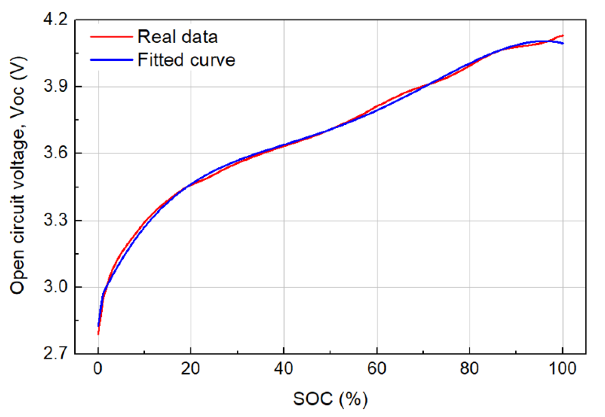
In this section, we identify the internal parameters of the built battery model including VOC, R0, Rp, Cp, and Ms. This requires the experiment data including current and voltage across battery terminals. The VOC of the battery is the potential difference between the poles of the battery in the no load state. In order to obtain open-circuit voltage and the battery SOC curve, the battery was charged in the standard way and then completely discharged with a constant current. The battery was discharged from 100% to 0% in 5% steps, and the period between the two steps is in a no-load (open-circuit) state; this procedure is completed within 2 h to achieve stable VOC. From obtained data, the mathematical relationship between the SOC and VOC was built by using the nonlinear curve fitting, and the fitting results are shown in Equation (9) and Figure 7.
V O C = 2.926 + 0.044 × S O C 1 0.0012 × S O C 2 + 1.511 E 5 × S O C 3 6.72 E 8 × S O C 4
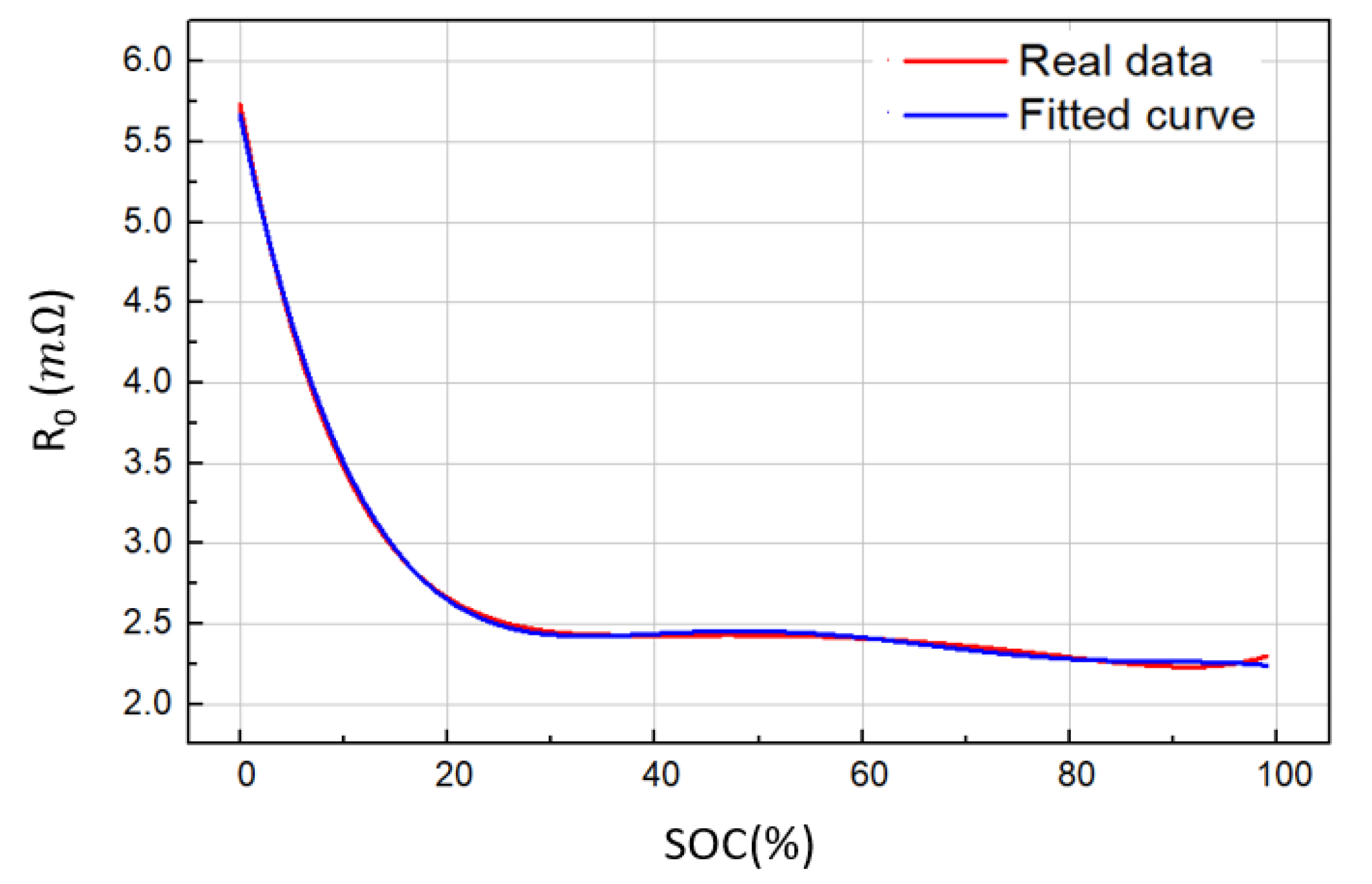
In the case of R0, it can also be determined by using the above battery discharge data. The value of R0 was calculated corresponding to the SOC of each period by dividing the value of the voltage drop by the discharge current, where voltage drop is the difference between the no load and loaded voltages. The variation of R0 according to the SOC is given in Figure 8, which fits into Equation (10).
R 0 = 5.7 E 3 3.4 E 2 S O C 1 + 0.146 S O C 2 0.326 S O C 3 + 0.415 S O C 4 0.29 S O C 5 + 0.094 S O C 6 6.4 E 3 S O C 7
From the results of VOC and R0, we can define the functions of Ms according to the SOC as below.
M s = 14.885 + 130.43 × S O C 1     588.464 × S O C 2 + 1381.381 × S O C 3 1889.537 × S O C 4
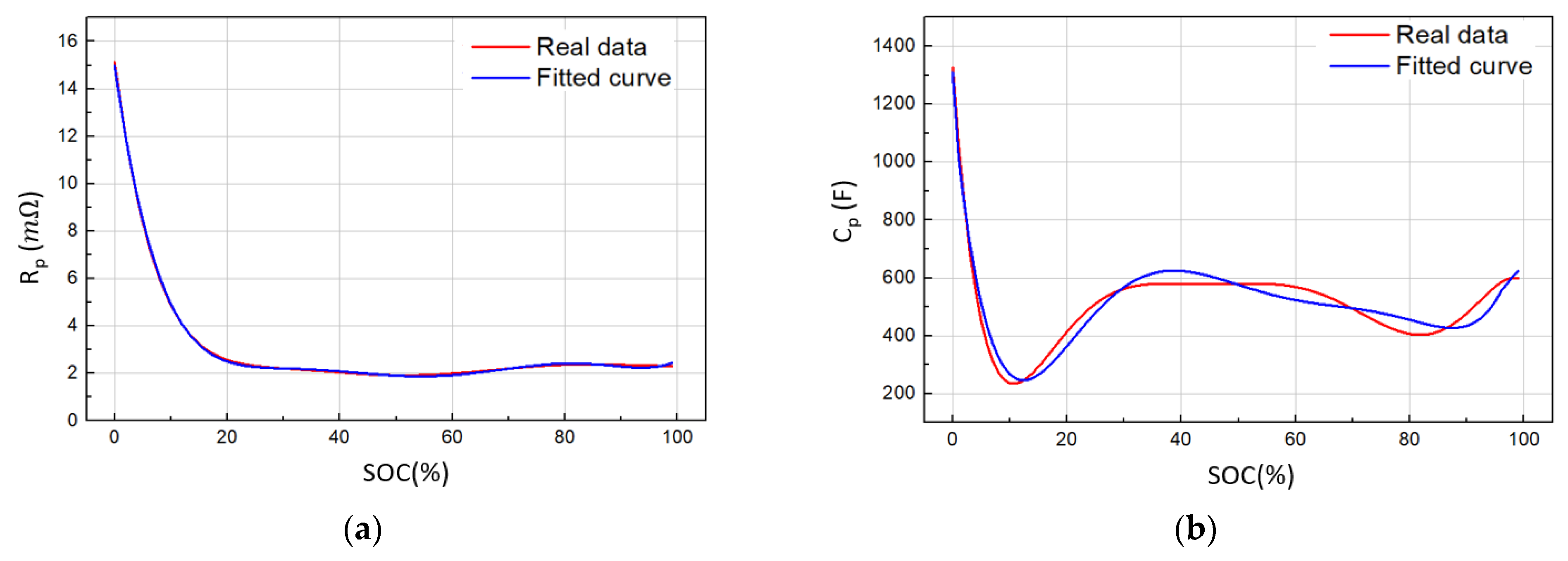
In order to identify the remaining battery parameters, Rp and Cp, the Matlab toolbox “Parameter estimate”, which is a powerful interface for battery parameter identification, was used. The obtained functions of Rp and Cp according to the SOC are shown in Equations (12) and (13), respectively. Figure 9 describes the variation of Rp and Cp according to the SOC.
R P = 0.015 0.18 S O C 1 + 1.052 S O C 2 3.28 S O C 3 + 5.798 S O C 4 5.82 S O C 5 + 3.08 S O C 6 0.67 S O C 7
C P = 1.3 E 3     2.8 E 4 × S O C + 2.6 E 5 × S O C 2     1.09 E 6 × S O C 3 + 2.4 E 6 × S O C 4     3.08 E 6 × S O C 5 + 2.01 E 6 × S O C 6     5.3 E 5 × S O C 7

3.3.3. SOC Estimation Model with the EKF

This algorithm combines the Thevenin battery model with the Ah integration method; the SOC and Vp represent the system state variables, the current represents input variables, and the battery terminal voltage represents the output variable. Figure 10 shows the diagram of the SOC estimation method using the EKF.
The use of the EKF requires the linearization of the state equations around the operating point for each sample. This algorithm is described in detail as follows:
-
Definition of the battery model with the state Equation (8)
-
Definition of the noise matrices: Q = E { v k , v k T } and R = E { w k , w k T }
-
Initializing the state variable, x 0 + = x 0 and the estimation error P 0 + = P 0
-
Prediction of the state variables, x k = [ S O C ( k ) , V p ( k ) ] at time k by the Equations (6) and (7) from the measured current I L ( k )
-
Linearization by calculating Jacobians: F = f ( x k , u k ) x k | x k + and H = h ( x k , u k ) x k | x k +
-
Prediction of the covariance matrix Pk (estimation error): P k = F P k 1 + F T + Q
-
Computation of the Kalman gain, Kg: K g = P k H T ( H P k H T + R ) 1
-
Update the new SOC based on the measured voltage, V L ( k ) and the output variable V L ( k ) :
S O C ( k ) + = S O C ( k ) + K g [ V ( k ) V ( k ) ]
-
Update the estimation error, P k to P k + for the next time step (k + 1): P k + = ( I L ( k ) K g H ) P k

3.4. Combination of the EKF and ANN for the SOC Estimation

In the case of using the EKF, the battery model was built for the SOC estimation based on the voltage and current characteristics. However, the battery is a dynamic system, and with a long operation time, the internal parameters of the battery model can be changed by other factors such as temperature, load changes, and SOC. These can cause errors in the SOC estimation model, and the battery modeling is very complex when considering them. With the method using the ANN, there were only three inputs including the voltage, current, and temperature of the present sample, and there was no information in the previous sample. This can cause a large dimension and high computation on the network. As the above results, the designed network had 4 hidden layers with 64 neurons in each layer, which means that the weight and bias matrices can take over a large amount of memory in the MCU and make it difficult to handle computation.
To solve the above-mentioned problems, we suggested a SOC estimation method combining the EKF with ANN as shown in Figure 11. The EKF model was applied to determine the battery SOC in the previous sample, SOC(k − 1), based on the measured values of the previous voltage, VL(k − 1) and the current, IL(k − 1). This SOC value was used as one input of an ANN to estimate the SOC in the present sample, SOC(k). The ANN was designed with four inputs including the measured voltage, VL(k), current, IL(k), and temperature, T(k) at the present sample. The EKF is incorporated with the ANN to adapt to the dynamic environments, and the SOC(k − 1) generated by the EKF takes into account battery hysteresis and measurement noise. Thereby, the accuracy and reliability of the SOC estimation can be improved.
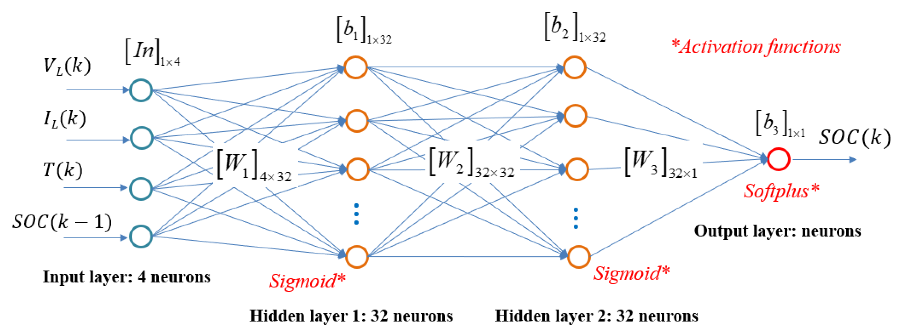
In this method, the designed EKF model in the previous section was kept to use, and the ANN was designed and trained again with the same battery dataset. The final specifications of the ANN are shown in Table 5. This network only needs two hidden layers, and each hidden layer had 32 neurons. The required memory and computation time in the MCU are significantly reduced. The detailed configuration of the designed ANN including the input layer, hidden layers, output layer, number of neurons in each layer, weight matrices, bias matrices, and activation functions are described in Figure 12.
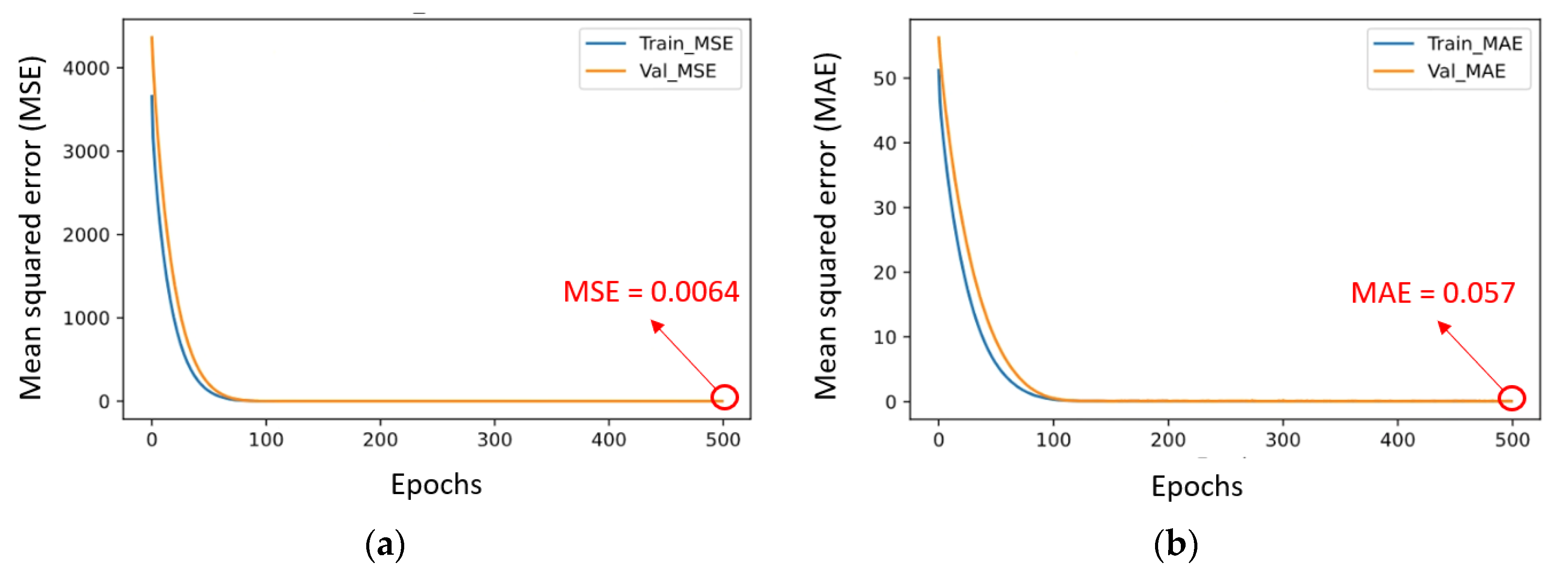
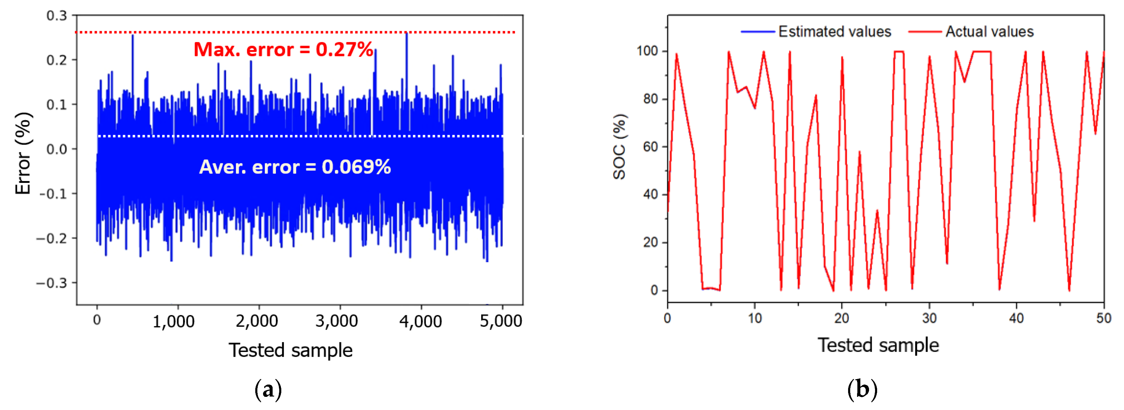
The network training was also performed in 500 epochs, and the performances of the redesigned ANN are shown in Figure 13. The MSE and MAE in the final epoch are approximately 0.0064 and 0.057, respectively, which are much lower than that of the ANN using three inputs. The trained model was also tested randomly with 5,000 samples to compare the actual and estimated SOC. The maximum and average errors of the estimated SOC were 0.27% and 0.069%, respectively, as shown in Figure 14.

4. Experiment Results and Discussions

4.1. Implementations of the SOC Estimation Methods in the Smart BMS

To validate the proposed SOC estimation methods, we applied them to the SOC estimation function of the BMS in an experimental test with a real LiB pack. First, we implemented a real-time SOC estimation based on the ANN. Then, the SOC estimations based on the EKF and the EKF-ANN were implemented in offline experiments by using the MATLAB program. These models were built to calculate the SOC from the experiment data acquired using the ANN. Finally, the obtained results of three methods were compared with the reference SOC, which was calculated from the measured battery capacity.
Using the ANN, the SOC was estimated based on the average voltage and current of the battery cells and the temperature in the battery pack. The SOC estimation function was built by C programming language on the master MCU STM32F205, which has a flash memory of up to 1 Mbyte. In the designed ANN, there were three 64 × 64 weight matrices and four 1x64 bias matrices in the hidden layers, and it took about 24 ms for calculation speed. The SOC was calculated in each sampling time of 1 s with the full charge and discharge of the battery pack. We found no problems with the memory and operation of the master MCU during the experiment. A monitoring system was also facilitated for the BMS as shown in Figure 15. The main interface of the monitoring system includes the contents listed below:
(1)
Configuration of the BMS
(2)
Measurement values including SOC, local time, and BMS version
(3)
Status of the BMS including warming, detection, state, and status
(4)
Summary of main measurement values
(5)
Serial communications with the BMS
(6)
Command to read and write the alarm and cut-off values
(7)
Calibration of the pack voltage and current values
(8)
External inputs to block the relay
(9)
Main screen displaying measurement values in the master and slave MCUs

4.2. Experiment Results of the SOC Estimation Methods

Since the proposed SOC estimation methods were built based on the battery data, these methods only valid under the experimental conditions similar to the range of battery data collected as follows:
-
After measuring the voltage and current of the entire battery pack, calculate the average value of the voltage and current of one cell,
-
Battery pack is discharged and charged with a constant current of 1.7 A in each cell,
-
Cell voltage range is 2.6–4.2 V,
-
Temperature range of the battery pack is 19~42 °C.
In the experiment, we first performed the SOC estimation using the ANN in real-time. The average voltage and current of the cells and the measured temperature during the discharge and charge processes of the battery pack are described in Figure 16. The battery pack was fully discharged and charged with the same currents of 1.7 A in each cell, which were similar to the trained battery dataset. The temperature was measured at the center of the battery pack, and the temperature range was from 19 °C to 38 °C.
Figure 17 shows the experimental results of the online SOC estimation using the ANN, and the estimated SOC was compared with the reference SOC. As a result, the maximum SOC errors in the discharge and charge processes were 2.3% and 2.6%, respectively. This result has satisfied the initial design target of the SOC estimation error for the smart BMS.
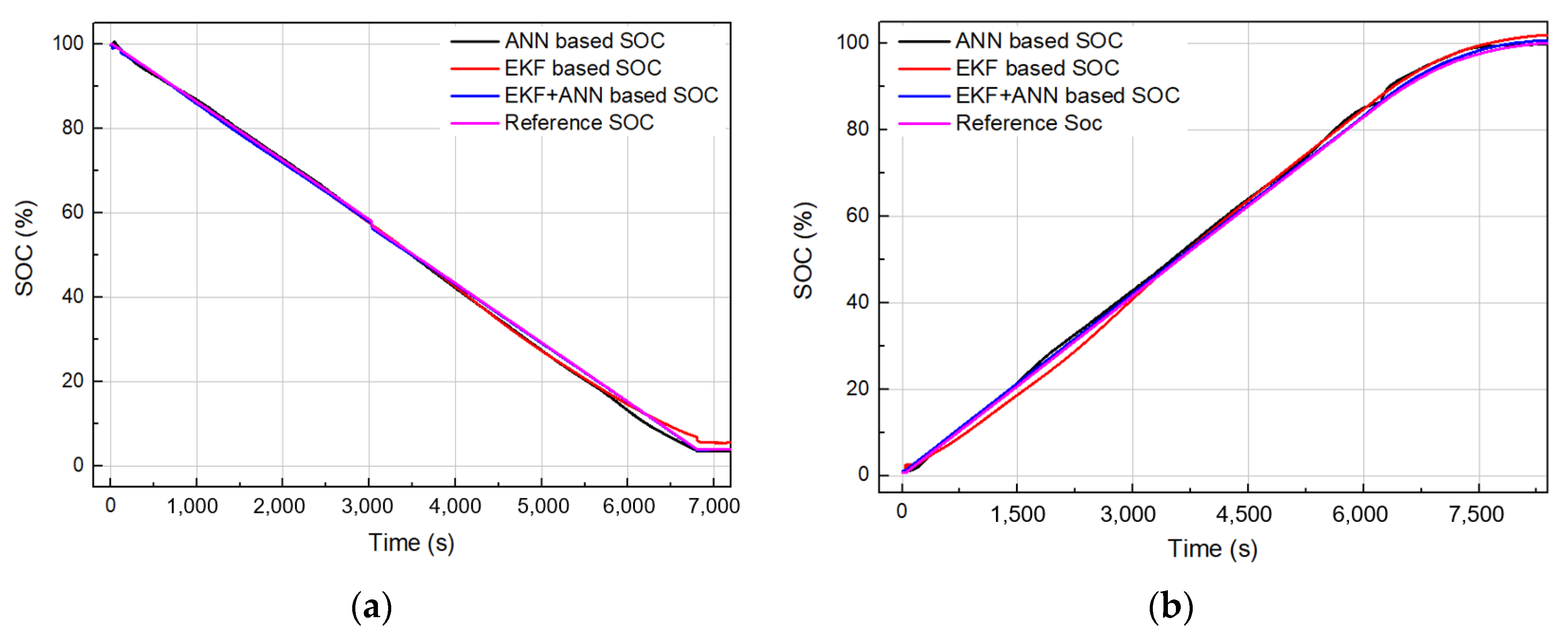
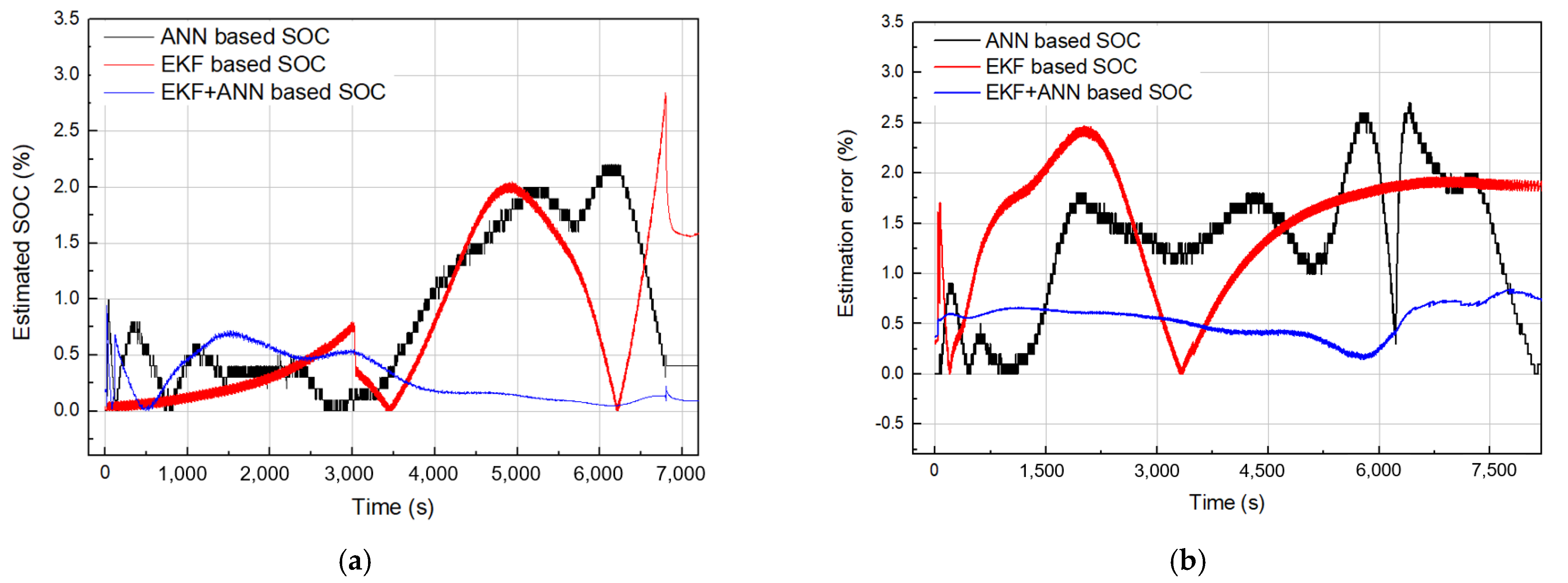
Next, the above experiment data including the battery voltage, current, and temperature were used to calculate the SOC offline using the other two methods in the Matlab simulation model. Figure 18 shows the comparison of the SOC estimation results using three methods with the reference SOC during the discharge and charge processes of the battery. The detailed absolute SOC errors of each method are given in Figure 19 and Table 6. Using the EKF, the maximum SOC errors in the discharge and charge processes were 2.8% and 2.4%, respectively, which were similar to that of using the ANN. We found the significant improvement for the SOC estimation by combining the EKF with ANN, which had the SOC error of less than 1%. Comparisons were made with other SOC estimation methods [37,38,39,40,41,42,43,44,45,46,47,48,49] and the maximum estimation errors are summarized in Table 7. Through this, it was confirmed that the proposed method guarantees the accuracy of SOC estimation similar to or better than other methods.

4.3. Discussions

From the above experimental results, it can be seen that the SOC estimation methods proposed in this study were accurate and satisfied the requirements of the designed smart BMS. However, there are still issues to be investigated. The performances of the method were evaluated when the battery pack was discharged and charged with a constant current. In a real battery system such as an EV, the load current continuously changes according to the vehicle speed. Therefore, to improve the quality of the battery modeling in the EKF method, the dynamic characteristics of the battery must be considered. Applying an ANN to EV requires more battery data trained with a dynamic current profile. In addition, other important issues of SOC estimation and BMS design, such as cell balancing and battery capacity fade, have not yet been considered. During long-term operation, more experiments need to be performed to collect battery data for each cell and analyze the cathode chemistry of the cells entirely. The next study will consider these issues and improve the accuracy of the SOC estimation method for the LiBs in various real systems.

5. Conclusions

The authors proposed effective SOC estimation methods based on the EKF and ANN for a LiB pack in a smart BMS. Detailed configurations and specifications of the smart BMS and LiB pack were presented. First, an ANN was used to build an SOC estimation model, which was trained and tested using a real battery dataset including voltage, current, temperature, and measured SOC over 20 cycles. Inputs of the designed network consisted of voltage, current, and temperature, and output was the estimated SOC of the battery. The design process for the ANN was described in detail. The Google TensorFlow open-source library was used to design and optimize the network configurations. Next, we developed a SOC estimation algorithm using the EKF, in which the LiB model was studied and a Thevenin model was developed to combine it with the Ah integration method. The current and terminal voltage of the battery represent the input variables, and the SOC represents the output variable. Finally, the EKF-ANN was proposed to improve the shortcomings of the above two methods, where the ANN was redesigned by adding one more input of the previous SOC determined using the EKF method. Both methods were confirmed through experiments performed on real battery data collected from the battery pack consisting of the LIB 18,650 35E cells at 4.2 V and 3.4 Ah. With the ANN and EKF, the SOC estimation performances were almost similar with a maximum SOC errors of 2.4% to 2.8%. Meanwhile, the use of the EKF-ANN significantly improved the accuracy of SOC estimation with less than 1% error. We are confident that the results of this study can be effectively applied to a smart BMS for industrial energy storage systems.

Author Contributions

Conceptualization, methodology: V.Q.D., M.-C.D. and C.S.K.; writing-original draft preparation: V.Q.D.; experiment support: B.Z., C.-H.D., L.J. and M.-K.L.; validation, writing-review and editing: M.-C.D. and B.Z.; project administration: J.H.B.; supervision: M.P. All authors have read and agreed to the published version of the manuscript.

Funding

This research was supported by the “Development of high precision Smart-BMS for fire prevention with HKF and Deep Learning” project of IES Co., LTD (Ho Chi Minh City, Vietnam) and Korea Electrotechnology Research Institute.

Institutional Review Board Statement

Not applicable.

Informed Consent Statement

Not applicable.

Data Availability Statement

Data is contained within the article.

Conflicts of Interest

The authors declare no conflict of interest.

References

  1. Khalid, M.; Sheikh, S.S.; Janjua, A.K.; Khalid, H.A. Performance validation of electric vehicle’s battery management system under state of charge estimation for lithium-ion battery. In Proceedings of the 2018 International Conference on Computing, Electronic and Electrical Engineering (ICE Cube), Quetta, Pakistan, 12–13 November 2018; pp. 1–5. [Google Scholar] [CrossRef]
  2. Zheng, M.X.; Qi, B.J.; Du, X.W. Dynamic model for characteristics of Li-ion battery on electric vehicle. In Proceedings of the 2009 4th IEEE Conference on Industrial Electronics and Applications, Xian, China, 25–27 May 2009; pp. 2867–2871. [Google Scholar] [CrossRef]
  3. Chen, T.M.; Jin, Y.; Lv, H.Y.; Yang, A.T.; Liu, M.Y.; Chen, B.; Xie, Y.; Chen, Y. Applications of Lithium-Ion Batteries in Grid-Scale Energy Storage Systems; Transactions of Tianjin University: Tianjin, China, 2020; Volume 26, pp. 208–217. [Google Scholar] [CrossRef] [Green Version]
  4. Mehr, T.H.; Masoum, M.A.S.; Jabalameli, N. Grid-connected Lithium-ion battery energy storage system for load leveling and peak shaving. In Proceedings of the 2013 Australasian Universities Power Engineering Conference (AUPEC), Hobart, Australasia, 29 September 2013; pp. 1–6. [Google Scholar] [CrossRef]
  5. Thorbergsson, E.; Knap, V.; Swierczynski, M.; Stroe, D.; Teodorescu, R. Primary Frequency Regulation with Li-Ion Battery Based Energy Storage System-Evaluation and Comparison of Different Control Strategies. In Proceedings of the Intelec 2013 35th International Telecommunications Energy Conference, Smart Power and Efficiency, Hamburg, Germany, 13–17 October 2013; pp. 1–6. [Google Scholar]
  6. Byrne, R.H.; Hamilton, S.; Borneo, D.R.; Olinsky-Paul, T.; Gyuk, I. The value proposition for energy storage at the sterling municipal light department. In Proceedings of the 2017 IEEE Power & Energy Society General Meeting, Chicago, IL, USA, 16–20 July 2017; pp. 1–5. [Google Scholar] [CrossRef]
  7. Hannan, M.A.; Hoque, M.M.; Hussain, A.; Yusof, Y.; Ker, P.J. State-of-the-Art and Energy Management System of Lithium-Ion Batteries in Electric Vehicle Applications: Issues and Recommendations; IEEE: Piscataway, NJ, USA, 2018; Volume 6, pp. 19362–19378. [Google Scholar] [CrossRef]
  8. Duan, J.; Tang, X.; Dai, H.; Yang, Y.; Wu, W.; Wei, X.; Huang, Y. Building Safe Lithium-Ion Batteries for Electric Vehicles: A Review. Electrochem. Energ. Rev. 2020, 3, 1–42. [Google Scholar] [CrossRef] [Green Version]
  9. How, D.N.T.; Hannan, M.A.; Hossain Lipu, M.S.; Ker, P.J. State of Charge Estimation for Lithium-Ion Batteries Using Model-Based and Data-Driven Methods: A Review; IEEE: Piscataway, NJ, USA, 2019; Volume 7, pp. 136116–136136. [Google Scholar] [CrossRef]
  10. Naguib, M.; Kollmeyer, P.; Emadi, A. Lithium-Ion Battery Pack Robust State of Charge Estimation, Cell Inconsistency, and Balancing: Review; IEEE: Piscataway, NJ, USA, 2021. [Google Scholar] [CrossRef]
  11. Mohamed, A.T. A review paper on batteries charging systems with the state of charge determination techniques. In Proceedings of the 2nd Smart Cities Symposium (SCS 2019), Bahrain, Bahrain, 24–26 March 2019; pp. 1–6. [Google Scholar] [CrossRef]
  12. Yuan, S.; Wu, H.; Yin, C. State of Charge Estimation Using the Extended Kalman Filter for Battery Management Systems Based on the ARX Battery Model. Energies 2013, 6, 444–470. [Google Scholar] [CrossRef]
  13. He, H.; Xiong, R.; Zhang, X.; Sun, F.; Fan, J. State-of-Charge Estimation of the Lithium-Ion Battery Using an Adaptive Extended Kalman Filter Based on an Improved Thevenin Model. IEEE Trans. Veh. Technol. 2011, 60, 1461–1469. [Google Scholar] [CrossRef]
  14. Chitnis, M.S.; Pandit, S.P.; Shaikh, M.N. Electric Vehicle Li-Ion Battery State of Charge Estimation Using Artificial Neural Network. In Proceedings of the 2018 International Conference on Inventive Research in Computing Applications (ICIRCA), Coimbatore, India, 11–12 July 2018; pp. 992–995. [Google Scholar] [CrossRef]
  15. Xiong, R.; Cao, J.; Yu, Q.; He, H.; Sun, F. Critical Review on the Battery State of Charge Estimation Methods for Electric Vehicles; IEEE: Piscataway, NJ, USA, 2018; Volume 6, pp. 1832–1843. [Google Scholar] [CrossRef]
  16. Manthopoulos, A.; Wang, X. A Review and Comparison of Lithium-Ion Battery SOC Estimation Methods for Electric Vehicles. In Proceedings of the IECON 2020 The 46th Annual Conference of the IEEE Industrial Electronics Society, Singapore, 18–21 October 2020; pp. 2385–2392. [Google Scholar] [CrossRef]
  17. Chang, W.Y. The State of Charge Estimating Methods for Battery: A Review. Int. Sch. Res. Not. 2013, 2013, 953792. [Google Scholar] [CrossRef]
  18. Zhang, R.; Xia, B.; Li, B.; Cao, L.; Lai, Y.; Zheng, W.; Wang, H.; Wang, W.; Wang, M. A Study on the Open Circuit Voltage and State of Charge Characterization of High-Capacity Lithium-Ion Battery under Different Temperature. Energies 2018, 11, 2408. [Google Scholar] [CrossRef] [Green Version]
  19. Nugroho, A.; Rijanto, E.; Wijaya, F.D.; Nugroho, P. Battery state of charge estimation by using a combination of Coulomb Counting and dynamic model with adjusted gain. In Proceedings of the 2015 International Conference on Sustainable Energy Engineering and Application (ICSEEA), Bandung, Indonesia, 5–7 October 2015; pp. 54–58. [Google Scholar] [CrossRef]
  20. Cuadras, A.; Kanoun, O. SoC Li-ion battery monitoring with impedance spectroscopy. In Proceedings of the 2009 6th International Multi-Conference on Systems, Signals and Devices, Djerba, Tunisia, 23–26 March 2009; pp. 1–5. [Google Scholar] [CrossRef]
  21. Spagnol, P.; Rossi, S.; Savaresi, S.M. Kalman Filter SoC estimation for Li-Ion batteries. In Proceedings of the2011 IEEE International Conference on Control Applications (CCA), Denver, CO, USA, 28–30 September 2011; pp. 587–592. [Google Scholar] [CrossRef]
  22. Rahmoun, A.; Biechl, H.; Rosin, A. SOC estimation for Li-Ion batteries based on equivalent circuit diagrams and the application of a Kalman filter. In Proceedings of the 2012 Electric Power Quality and Supply Reliability, Tartu, Estonia, 11–13 June 2012; pp. 1–4. [Google Scholar] [CrossRef]
  23. Lee, S.J.; Kim, J.H.; Lee, J.M.; Cho, B.H. The State and Parameter Estimation of an Li-Ion Battery Using a New OCV-SOC Concept. In Proceedings of the 2007 IEEE Power Electronics Specialists Conference, Orlando, FL, USA, 17–21 June 2007; pp. 2799–2803. [Google Scholar] [CrossRef]
  24. Yatsui, M.W.; Bai, H. Kalman filter based state-of-charge estimation for lithium-ion batteries in hybrid electric vehicles using pulse charging. In Proceedings of the 2011 IEEE Vehicle Power and Propulsion Conference, Chicago, IL, USA, 6–9 September 2011; pp. 1–5. [Google Scholar] [CrossRef]
  25. Haoran, L.; Liangdong, L.; Xiaoyin, Z.; Mingxuan, S. Lithium Battery SOC Estimation Based on Extended Kalman Filtering Algorithm. In Proceedings of the 2018 IEEE 4th International Conference on Control Science and Systems Engineering (ICCSSE), Wuhan, China, 21–23 August 2018; pp. 231–235. [Google Scholar] [CrossRef]
  26. Yang, S.; Zhou, S.; Hua, Y.; Zhou, X.A.; Liu, X.H.; Pan, Y.W.; Ling, H.P.; Wu, B. A parameter adaptive method for state of charge estimation of lithium-ion batteries with an improved extended Kalman filter. Sci. Rep. 2021, 11, 5805. [Google Scholar] [CrossRef] [PubMed]
  27. Ismail, M.; Dlyma, R.; Elrakaybi, A.; Ahmed, R.; Habibi, S. Battery state of charge estimation using an Artificial Neural Network. In Proceedings of the 2017 IEEE Transportation Electrification Conference and Expo (ITEC), Chicago, IL, USA, 22–24 June 2017; pp. 342–349. [Google Scholar] [CrossRef]
  28. Almeida, G.C.S.; Souza, A.C.Z.d.; Ribeiro, P.F. A Neural Network Application for a Lithium-Ion Battery Pack State-of-Charge Estimator with Enhanced Accuracy. Proceedings 2020, 58, 33. [Google Scholar] [CrossRef]
  29. Saji, D.; Babu, P.S.; Ilango, K. SoC Estimation of Lithium-Ion Battery Using Combined Coulomb Counting and Fuzzy Logic Method. In Proceedings of the 2019 4th International Conference on Recent Trends on Electronics, Information, Communication & Technology (RTEICT), Bangalore, India, 17–18 May 2019; pp. 948–952. [Google Scholar] [CrossRef]
  30. Rivera-Barrera, J.P.; Muñoz-Galeano, N.; Sarmiento-Maldonado, H.O. SoC Estimation for Lithium-ion Batteries: Review and Future Challenges. Electronics 2017, 6, 102. [Google Scholar] [CrossRef] [Green Version]
  31. Liu, K.; Li, K.; Peng, Q.; Zhang, C. A brief review on key technologies in the battery management system of electric vehicles. Front. Mech. Eng. 2019, 14, 47–64. [Google Scholar] [CrossRef] [Green Version]
  32. Vaideeswaran, V.; Bhuvanesh, S.; Devasena, M. Battery Management Systems for Electric Vehicles using Lithium-Ion Batteries. In Proceedings of the 2019 Innovations in Power and Advanced Computing Technologies (i-PACT), Vellore, India, 22–23 March 2019; pp. 1–9. [Google Scholar] [CrossRef]
  33. Ali, S.S.; Choi, B.J. State-of-the-Art Artificial Intelligence Techniques for Distributed Smart Grids: A Review. Electronics 2020, 9, 1030. [Google Scholar] [CrossRef]
  34. Lai, X.; Qin, C.; Gao, W.; Zheng, Y.; Yi, W. A State of Charge Estimator Based Extended Kalman Filter Using an Electrochemistry-Based Equivalent Circuit Model for Lithium-Ion Batteries. Appl. Sci. 2018, 8, 1592. [Google Scholar] [CrossRef] [Green Version]
  35. He, H.; Xiong, R.; Fan, J. Evaluation of Lithium-Ion Battery Equivalent Circuit Models for State of Charge Estimation by an Experimental Approach. Energies 2011, 4, 582–598. [Google Scholar] [CrossRef]
  36. Chen, M.; Rincon-Mora, G.A. Accurate Electrical Battery Model Capable of Predicting Runtime and I–V Performance; IEEE Transactions on Energy Conversion: Piscataway, NJ, USA, 2006; Volume 21, pp. 504–511. [Google Scholar] [CrossRef]
  37. Jiani, D.; Zhitao, L.; Youyi, W.; Changyun, W. A fuzzy logic-based model for Li-ion battery with SOC and temperature effect. In Proceedings of the 11th IEEE International Conference on Control & Automation (ICCA), Taichung, Taiwan, 18–20 June 2014; pp. 1333–1338. [Google Scholar] [CrossRef]
  38. Zheng, W.; Xia, B.; Wang, W.; Lai, Y.; Wang, M.; Wang, H. State of Charge Estimation for Power Lithium-Ion Battery Using a Fuzzy Logic Sliding Mode Observer. Energies 2019, 12, 2491. [Google Scholar] [CrossRef] [Green Version]
  39. Rao, R.P.; Bhat, R.S.; Ranjeeth, R.; Kavya, B.G. Implementing Fuzzy Logic to Improve the Accuracy of SoC Estimation for Li-ion Battery. Int. J. Eng. Res. Technol. 2020, 09, 937–941. [Google Scholar]
  40. Wu, S.; Chen, H.; Tsai, M.; Lin, T.; Chen, L. AC Impedance Based Online State-of-Charge Estimation for Li-ion Battery. In Proceedings of the 2017 International Conference on Information, Communication and Engineering (ICICE), Xiamen, China, 17–20 November 2017; pp. 53–56. [Google Scholar] [CrossRef]
  41. Xu, J.; Chris Mi, C.; Cao, B.G.; Cao, J.Y. A new method to estimate the state of charge of lithium-ion batteries based on the battery impedance model. J. Power Sources 2013, 233, 277–284. [Google Scholar] [CrossRef]
  42. Kim, T.; Qiao, W.; Qu, L. Real-time state of charge and electrical impedance estimation for lithium-ion batteries based on a hybrid battery model. In Proceedings of the 2013 Twenty-Eighth Annual IEEE Applied Power Electronics Conference and Exposition (APEC), Long Beach, CA, USA, 17–21 March 2013; pp. 563–568. [Google Scholar] [CrossRef]
  43. Guo, X.; Xu, X.; Geng, J.; Hua, X.; Gao, Y.; Liu, Z. SOC Estimation with an Adaptive Unscented Kalman Filter Based on Model Parameter Optimization. Appl. Sci. 2019, 9, 4177. [Google Scholar] [CrossRef] [Green Version]
  44. Wang, W.; Wang, X.T.; Xiang, C.; Wei, C.; Zhao, Y. Unscented Kalman Filter-Based Battery SOC Estimation and Peak Power Prediction Method for Power Distribution of Hybrid Electric Vehicles; IEEE: Piscataway, NJ, USA, 2018; Volume 6, pp. 35957–35965. [Google Scholar] [CrossRef]
  45. Mazzi, Y.; Sassi, H.B.; Errahimi, F.; Es-Sbai, N. State of charge estimation using extended kalman filter. In Proceedings of the 2019 International Conference on Wireless Technologies, Embedded and Intelligent Systems (WITS), Fez, Morocco, 3–4 April 2019; pp. 1–6. [Google Scholar] [CrossRef]
  46. Ciortea, F.; Rusu, C.; Nemes, M.; Gatea, C. Extended Kalman Filter for state-of-charge estimation in electric vehicles battery packs. In Proceedings of the 2017 International Conference on Optimization of Electrical and Electronic Equipment (OPTIM) & 2017 Intl Aegean Conference on Electrical Machines and Power Electronics (ACEMP), Brasov, Romania, 25–27 May 2017; pp. 611–616. [Google Scholar] [CrossRef]
  47. Cheng, Z.; Lv, J.K.; Liu, Y.L.; Yan, Z.H. Estimation of State of Charge for Lithium-Ion Battery Based on Finite Difference Extended Kalman Filter. J. Appl. Math. 2014, 2014, 10. [Google Scholar] [CrossRef] [Green Version]
  48. Baccouche, I.; Mlayah, A.; Jemmali, S.; Manai, B.; Essoukri Ben Amara, N. $Implementation of a Coulomb counting algorithm for SOC estimation of Li-Ion battery for multimedia applications. In Proceedings of the 2015 IEEE 12th International Multi-Conference on Systems, Signals & Devices (SSD15), Mahdia, Tunisia, 16–19 March 2015; pp. 1–6. [Google Scholar] [CrossRef]
  49. Qaisar, S.M. Event-Driven Coulomb Counting for Effective Online Approximation of Li-Ion Battery State of Charge. Energies 2020, 13, 5600. [Google Scholar] [CrossRef]
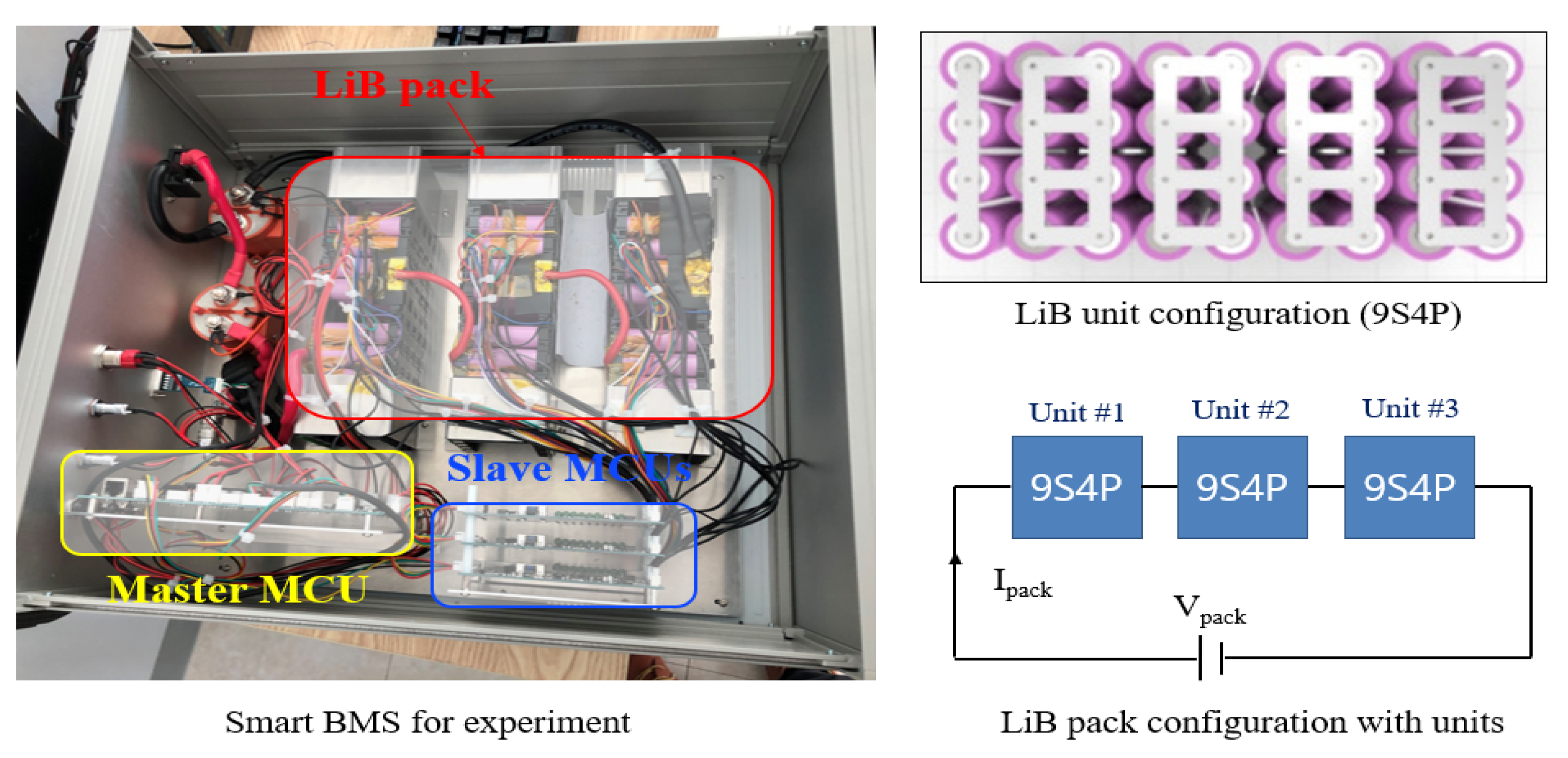
Figure 1. Configurations of the smart BMS and LiB pack.
Energies 14 02634 g001
Figure 2. Configuration of a neuron in the ANN.
Energies 14 02634 g002
Figure 3. Relationships between the inputs and output of the ANN.
Energies 14 02634 g003
Figure 4. Training performances of the ANN: (a) Mean squared error (MSE); and (b) Mean absolute error (MAE).
Energies 14 02634 g004
Figure 5. Test results of the trained ANN with 5,000 random samples: (a) error of the estimated SOC, and (b) estimated and actual SOCs.
Energies 14 02634 g005
Figure 6. Equivalent circuit of the Thevenin model for the LiB.
Energies 14 02634 g006
Figure 7. VOC and SOC curve of the LiB.
Energies 14 02634 g007
Figure 8. R0 and SOC curve of the LiB.
Energies 14 02634 g008
Figure 9. Variation of Rp and Cp according to SOC: (a) Rp; and (b) Cp.
Energies 14 02634 g009
Figure 10. Diagram of the SOC estimation method based on the EKF.
Energies 14 02634 g010
Figure 11. Configuration of the SOC estimation method combining the EKF with ANN.
Energies 14 02634 g011
Figure 12. Detailed configuration and parameters of the designed ANN.
Energies 14 02634 g012
Figure 13. Training performances of the redesigned ANN: (a) MSE, and (b) MAE.
Energies 14 02634 g013
Figure 14. Test results of the redesigned ANN with 5,000 random samples: (a) error of estimated SOC, and (b) estimated and actual SOCs.
Energies 14 02634 g014
Figure 15. Monitoring system for the smart BMS.
Energies 14 02634 g015
Figure 16. Experiment results for the battery pack characteristics: (a) discharge; and (b) charge.
Energies 14 02634 g016
Figure 17. Experiment results of the SOC estimation using the ANN: (a) discharge; and (b) charge.
Energies 14 02634 g017
Figure 18. Experiment results of the SOC estimations using three methods: (a) Discharge; and (b) Charge.
Energies 14 02634 g018
Figure 19. Errors of the SOC estimations using three methods: (a) Discharge; and (b) charge.
Energies 14 02634 g019
Table 1. Detailed specifications of the smart BMS and LiB pack.
ItemsSpecificationsContents
1. BMS hardwareMaster BMS MCU32-bit STM32F207
Slave BMS MCU32-bit STM32F103
External communicationUART
Master-Slave communicationCAN 2.0
Power supply12 V
Temperature sensors4 ea.
Firmware toolST-Link Download
2. LiB cellModel18,650 35E
Capacity3.4 Ah (1 C)
Cell voltage2.5~4.2 V
3. LiB unit moduleConfiguration9-series and 4-parallel (9S4P)
Voltage/Capacity32.4 V/10.2 Ah
Energy330.48 Wh
4. LiB packConfiguration3 LiB units in series
Pack voltage67.5~113.4 V
Capacity10.2 Ah
Energy991.44 Wh
Table 2. Design targets of the smart BMS.
ItemsStandard [31,32]TargetUnitEvaluation Method
Active Cell Balancing±10±8mVDigital multimeter
Voltage measurement accuracy±5±1mVDigital multimeter
Current measurement accuracy±2±1%Charger/Discharger
Temperature measurement accuracy±1±0.5°CThermostat
SOC estimation error±5±3%Charger/Discharger
Table 3. Design process and design factors for the ANN.
StepContentsRemarks
1Data collection and pre-processing for training the network
-
Training dataset (%)
-
Validation dataset (%)
-
Test dataset (%)
2Selecting the network topology and configuring the layers and neurons
-
Input layer: set the inputs
-
Number of hidden layers, and number of neurons in each layer
-
Output layer: set the output
3Selecting the learning rate, α
-
0 < α < 1
4Selecting the activation function
-
Sigmoid, Linear, Tanh, ReLu, …
5Selecting the loss function and metrics for the training process
-
Mean squared error (MSE)
-
Mean absolute error (MAE)
-
Metrics = [MSE, MAE]
6Selecting the learning function (optimizer)
-
Adam, AdaDelta, SGD, …
Table 4. Final specifications of the ANN for the SOC estimation.
SpecificationsANN
Number of inputs of the network3
Number of hidden layers of the network4
Number of outputs of the network1
Number of neurons in each hidden layer64
Activation function in hidden layersSigmoid
Activation function in the output layerSoftplus
Adapting learning functionAdam
Learning rate0.001
Loss functionMSE
Accuracy metrics[MSE, MAE]
Table 5. Final specifications of the ANN combined with the EKF.
SpecificationsANN
Number of inputs of the network4
Number of hidden layers of the network2
Number of outputs of the network1
Number of neurons in each hidden layer32
Activation function in the hidden layersSigmoid
Activation function in the output layerSoftplus
Adapting learning functionAdam
Learning rate0.001
Loss functionMSE
Accuracy metrics[MSE, MAE]
Table 6. Summary of the errors in the SOC estimations using three methods.
MethodsANN BasedEKF BasedEKF+ANN Based
DischargeMaximum error2.3%2.8%0.9%
Average error0.86%0.77%0.29%
ChargeMaximum error2.6%2.4%0.8%
Average error1.26%1.53%0.55%
Table 7. Comparison of the designed SOC estimation methods with others.
SOC Estimation MethodsMaximum Estimation Errors
This studyANN based2.6%
EKF based2.8%
EKF+ANN based0.9%
Other studiesFuzzy logic based2.12% [37], 2.45% [38], 1.9% [39]
Impedance based4% [40], 1% [41], 2.3% [42]
Unscented Kalman Filter based1.22% [43], 1.5% [44]
Adaptive EKF based2% [45], 2.5% [46], 1.6% [47]
Coulomb counting3% [48], 4% [49]
Publisher’s Note: MDPI stays neutral with regard to jurisdictional claims in published maps and institutional affiliations.