Article

Optimization of Ferrites Structure by Using a New Core-Less Design Algorithm for Electric Vehicle Wireless Power Transfer

1
Power Electronics Research Centre, Department of Electrical Engineering, The Hong Kong Polytechnic University, Hong Kong, China
2
College of Mechatronics and Control Engineering, Shenzhen University, Shenzhen 518000, China
*
Author to whom correspondence should be addressed.
Energies 2021, 14(9), 2590; https://doi.org/10.3390/en14092590
Submission received: 17 March 2021 / Revised: 20 April 2021 / Accepted: 23 April 2021 / Published: 1 May 2021
(This article belongs to the Special Issue Advanced Electric Vehicle Techniques)

Abstract

:
In order to improve the customers’ continuous usage of electrical vehicles (EVs) and reduce the weight of the energy storage devices, wireless charging technology has been widely studied, updated, and commercialized in recent decades, regarding to its distinct superiority of great convenience and low risk. A higher coupling coefficient is the key factor that impacts the transmission efficiency, thus in most medium-power (hundreds of watts) to high-power (several kilowatts) wireless charging systems, ferrites are used to guide the magnetic flux and intensify the magnetic density. However, the weight of the ferrite itself puts an extra burden on the system, and the core loss during operation also reduces the total efficiency and output power. This paper proposes an optimized design algorithm based on a core-less method for the magnetic core, where the core loss and the coupling coefficient are consequently balanced, and the overall weight and efficiency of the system can be optimized. The iteration procedure is applied on the basis of removed ferrite length and thickness in the algorithm. In the simulation, a square coupler with a total volume of 300 mm × 150 mm, a circular coupler of 150 mm × 150 mm and a Double-D (DD) coupler of 300 mm × 150 mm are used to verify the advantages of the proposed method. The optimized ferrite structures are specific for each coupler shape, and the improvement is proved to be universal in current scale by means of 3-D finite element analysis.

1. Introduction

Wireless power transfer (WPT), more widely known as wireless charging technology, is a technology that transmits electrical energy across an air gap by generating an electromagnetic field. From low-power applications (such as electric toothbrushes, mobile phones) to high-power charging systems (such as EVs and railroad trains), wireless charging technology has been widely recognized, researched, and commercialized due to its convenience and intelligence in charging applications. However, the most criticized shortcoming of WPT is that its charging efficiency is lower compared to that of wired charging. Moreover, for EV contactless charging, due to the influence of the divergent magnetic field and the surrounding metal objects, a large amount of ferrite is required to guide the magnetic flux on both the transmitter and the receiver. This undoubtedly increases the weight of the vehicle, and in the ferrite, the core loss is inevitably increased.
The shapes of common wireless couplers in EV wireless charging are generally circular and rectangular. The circular coil can excite a stronger magnetic field in short distance transmission, and the efficiency is higher. However, the square coil has an advantage of tolerance with misalignment over the circular coil [1]. In other words, when the two coils are displaced horizontally or the air gap becomes larger, the mutual inductance between two circular coils has less robustness. Since the square coil can concentrate a larger magnetic field on the four sides and has more overlapped areas, it has a higher tolerance for misalignment [2]. A circular wireless charger with an air core is proposed by the author of the paper [3]. Although the transmission efficiency is increased by the structure of multiple coils, the coupling coefficient is much lower than that of the ferrite core coupler, which is only about 0.1~0.2. The double-D (DD) shape coupler has evolved based on the advantages of the square-shape coupler, and its structure is two square coils connected in series. In practical conditions with less misalignment, such as trams, DD-shaped coils with overlapping areas are also designed to strengthen the central magnetic field [4]. Based on the DD-shaped coupling coil, the normal designs of its compensation circuit, including series-series (SS), series-parallel (SP), parallel-series (PS), and parallel-parallel (PP), are classified and compared in [5]. A high-order compensation circuit is proposed to achieve multiple controllable outputs. It is also pointed out in the conclusion of this paper that no matter how large the mutual inductance is, the efficiency can be improved by designing an appropriate compensation circuit.
In order to generate high magnetic field and improve the coupling, an inductive iron based on inductive power transmission has been proposed, which inevitably increases the temperature by several degrees in one minute [6]. Although the heat should be the criterion and is sufficiently achieved in [6], such a temperature and loss will severely hinder the system efficiency in wireless charging, and some of the literature has also proposed ways to optimize the core structure. In [7], the authors made an asymmetric design of the magnetic core structure of the DD-shaped wireless charging coupler for EVs, and also confirmed that this design can avoid the difference between the peak and average voltage induced across the pickup coil and lengthening the fraction of the distance between two track coils available to transfer power to the electric vehicles (EVs). Ref [8] also proposed the use of DD and Q coils for electric vehicles that has been seen to be a recent trend for EV wireless coils. Combined with the finite element analysis, the aspect ratio of the coil and the ferrite can also be optimized to make the coupling of the system and the placement of the ferrite more effective [9,10,11,12,13,14,15,16]. In order to increase the robustness of the air core system during operation, it is often necessary to add additional circuits and coils to control the stability of the system [10]. Although these optimization methods and research can optimize the performance of the system, they do not involve the consideration of core loss. In the loss analysis, in addition to copper loss and component loss in the circuit, the core loss should also be included [17]. The efficiency and improvement in key reference papers are listed in Table 1.
The method of calculating the core loss is constantly changing and refining [18,19,20,21,22]. The most classic method is Hysteresis Models, which includes two branches, namely the Jiles–Atherton model and Preisach’s work. The principle of the Jiles–Atherton model is to use iterative processes to estimate parameters, whereas it is limited by the use of a large number of empirical parameters [23]. The Preisach’s work [24] can be extended to dynamic effects, while the recognition problems associated with the weight function have led to huge quantities of experimental work, which must be compared with the incremental increase in accuracy. The most widely used empirical equation now is Steinmetz’s original work dating back to the last century. The equation indicates that the core loss is composed of several empirical values, frequency, and peak magnetic field strength. The Modified Steinmetz equation (MSE) allows calculations to be performed in the time domain, as well as the feasibility of calculating irregular objects [18,22]. Regarding the core loss under the excitation of non-sinusoidal wave and rectangular wave, corresponding studies have been put forward to improve the empirical estimation method based on Steinmetz equation [19,20,21].
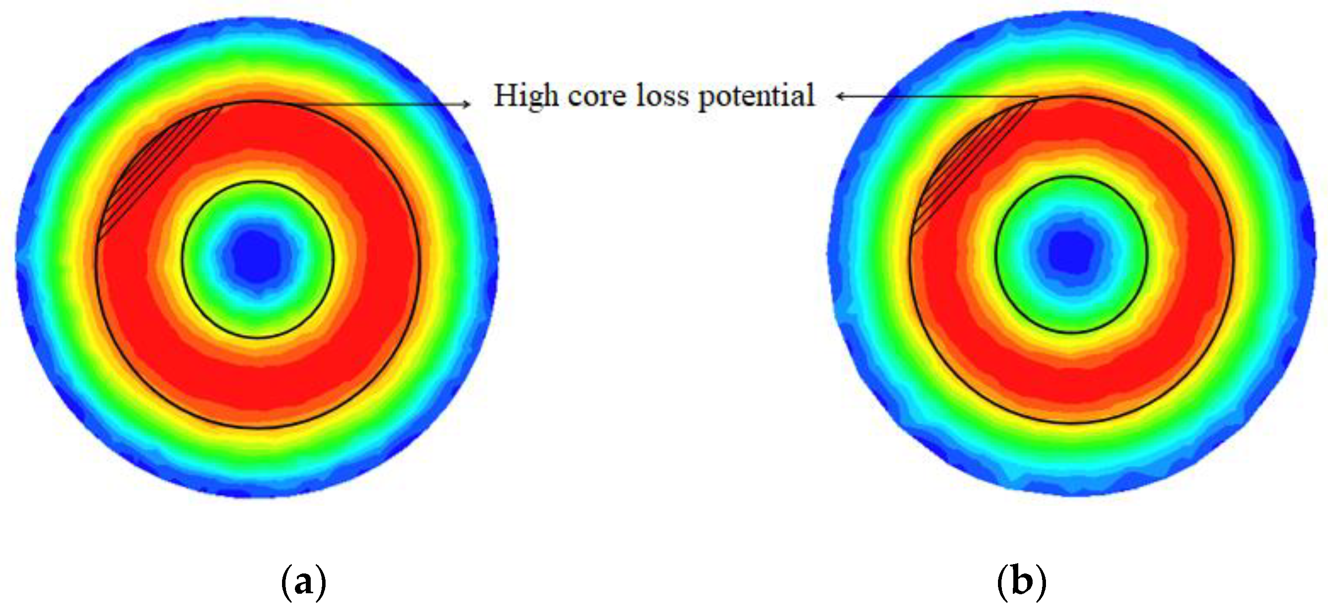
Although a large number of magnetic core calculation methods have been proposed and can be selected in different situations, many of the optimal design methods of the magnetic core structure are still only in the continuous simulation and experimental process, and there is no corresponding response to a certain shape of the coil [15]. Reference [15] proposed a magnetic core optimization method for DD-shaped coupling coils. Through the cooperation of FEA simulation software and MATLAB, the magnetic field distribution at different positions is analyzed, and the thickness of the magnetic core is optimized to make the magnetic field distribution more uniform. This optimization design also uses the weight equation and iterative algorithm to ensure the effectiveness of the optimization. However, the limitation of this optimized design is that it fails to consider the weight barrier caused by the increase in thickness. The winding loss due to wiring generates the reaction field that affects the overall loss [25]. This paper proposes an algorithm that can combine ferrite-less considerations with an iterative method to make optimization more practical.
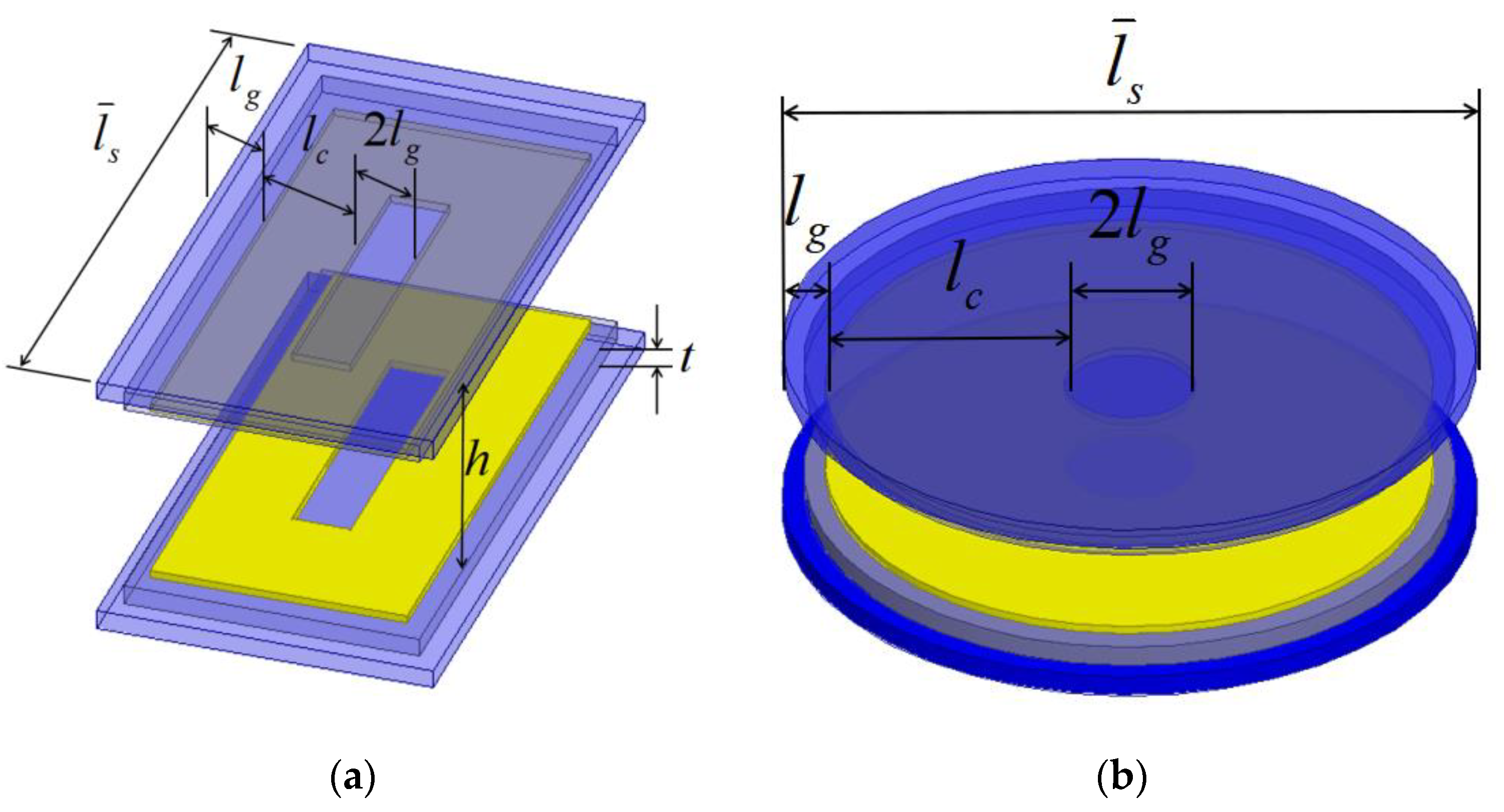
In order to make the overall efficiency of the system higher and also consider the actual user experience, the following principles should be considered when designing the ferrite structure of the coupler:
(1)
In order to make the output power higher, the necessary ferrite needs to be added to ensure a higher mutual inductance value and mutual inductance coefficient
(2)
By adding a compensation circuit, harmonics can be eliminated and electrical efficiency improved, and the ferrite structure needs to be optimized to reduce core loss
(3)
Due to the greater density of ferrite, the overall weight of the system needs to be considered during the design process.
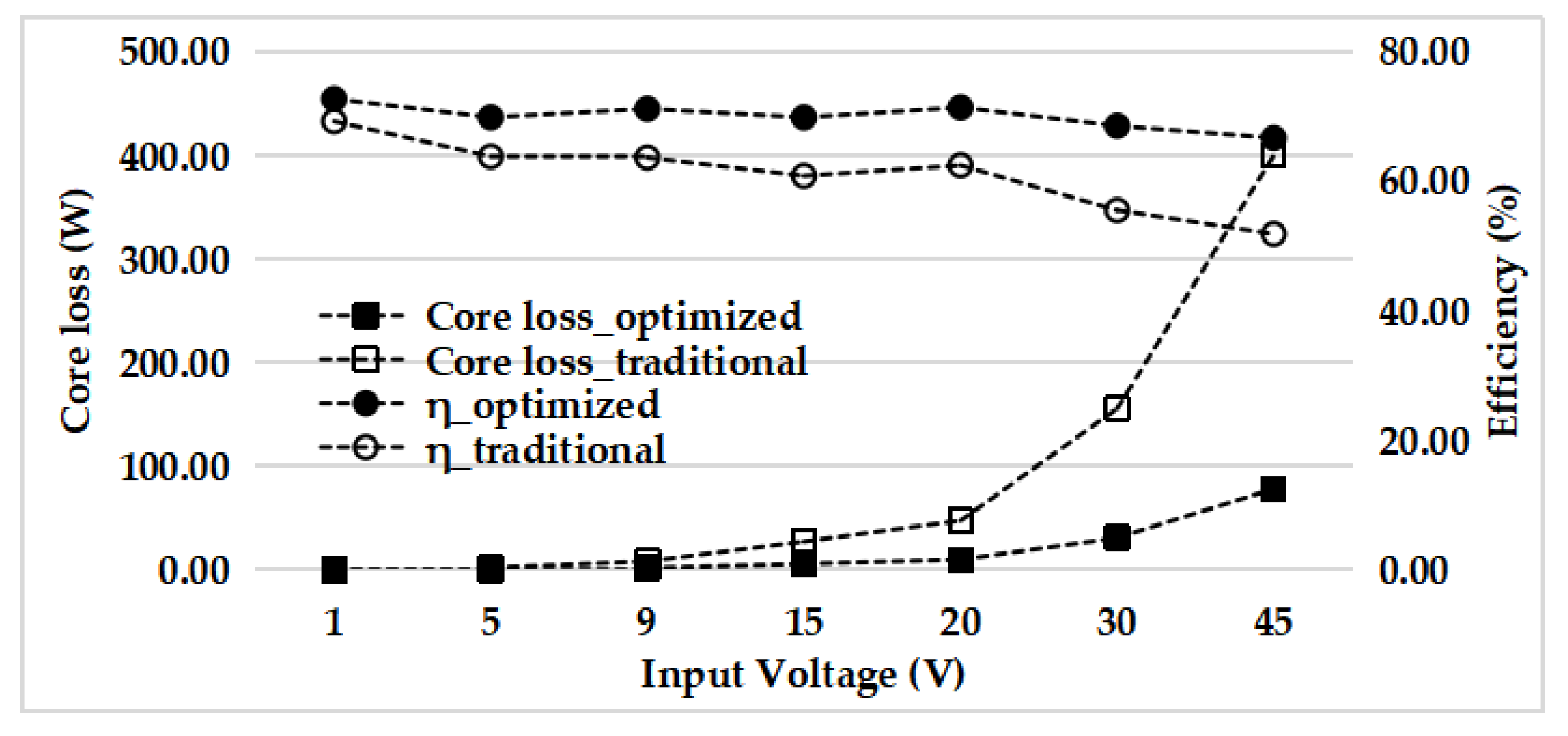
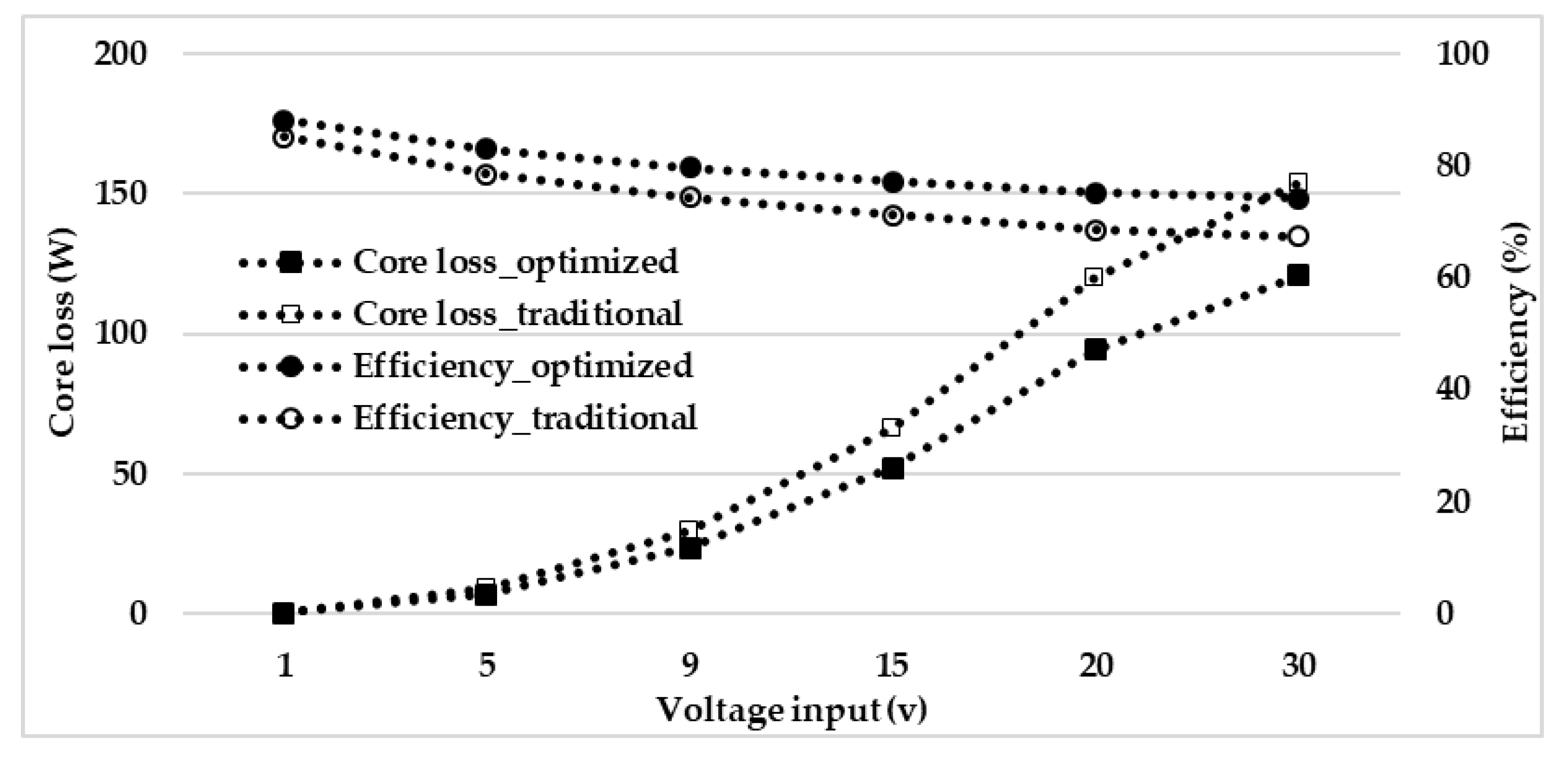
The second section of this article will introduce the derivation process of coupler efficiency and core loss. The relationship between the coupling coefficient and the ferrite coefficients will also be analyzed by the magnetic circuit equation in this section. In the analysis process, more detailed design suggestions will be put forward, and in the discussion section, the key factors will be analyzed by finite element simulation. In the third section, an optimization algorithm considering the system weight, efficiency, and core loss is proposed. Under the proposed design principles, by setting the weights and optimizing the cycle, the key parameters of the ferrite structure will be output. In order to prove the universality of this optimization method, in the fourth section, the circular, square, and DD coupler ferrites are optimized, respectively, and the system efficiency and core loss after optimization are verified on various power levels.

2. Derivation of Efficiency, Coupling Coefficient and Core Loss

2.1. System Efficiency and Output

A typical wireless charging system (shown in Figure 1a) consists of a DC voltage source, converter and rectifier, and a pair of couplers. Assuming that the converter does not generate switching losses, the system can be simplified to the equivalent circuit diagram of Figure 1b. Among them, U s is the input voltage, L l k p and L l k s are the leakage inductance of the primary and secondary sides, L m is the magnetizing inductance, and C p and C s are the compensation capacitors. R p and R s are conduction losses. Although the core loss does not appear as a linear resistance, it is still expressed as R c o r e in the equivalent circuit because it is proportional to the excitation current I m .
After dividing the circuit by following the Kirchhoff Voltage Law (KVL), the matrix can be derived as follows,
[ R p + R c o r e _ p + j ω L l k p + 1 j ω C p j ω M j ω M R L + R s + R c o r e _ s + j ω L l k p + 1 j ω C p ] [ I p I s ] = [ U S 0 ]
η = Re [ I s 2 R L ] Re [ U S I s ] × 100 %
Because the efficiency of the system is as shown in Equation (2), we can get the efficiency and output power expression of the system fused into the magnetic loss as
P O = ( ω M U S ) 2 R L [ ( R p + R c o r e _ p ) ( R s + R L + R c o r e _ s ) + ω 2 M 2 ] 2
η = R L R s + R L + R c o r e _ s + ( R p + R c o r e _ p ) [ ( R s + R L + R c o r e _ s ) / ω M ] 2
where M is the mutual inductance that is proportional to coupling coefficient.
M = k L p L s
It can be seen from Equations (3) and (4) that reducing the equivalent core impedance can improve the efficiency and power output of the system. However, because the mutual inductance M of the coil is related to the volume and placement of the magnetic core, simply reducing the volume of magnetic core will definitely reduce the coupling coefficient. In order to achieve the purpose of optimizing the energy density of the system, it is necessary to balance the core loss and the coupling coefficient. Therefore, the relationship between the coupling coefficient and the specific parameters of the coupler design must be further studied.

2.2. Coupling Coefficient

The coupling coefficient has an inalienable relationship with the size and structure of the coupling coil and the placement of the ferrite. The relationship between the coupling coefficients of the couplers of different structures and the system parameters can be derived from the analysis of the magnetic circuit and magnetic flux. For a pair of square or circular coupling coils (Figure 2a,b), their cross-sectional view can be represented by Figure 3a. The length of the coil represented by the yellow part is l c , the interval length of the coil winding is 2 l g , and the vertical air gap is h . Assuming that the boundary of the coupler is the farthest end of the ferrite, the uncovered gap on both sides of the coil is also l g . The thickness of the ferrite is l t , and for subsequent analysis, the longitudinal average length of the system is expressed as l ¯ s .
In order to better understand the magnetic circuit structure and facilitate calculation, it is assumed that the following conditions are established in the analysis:
(1)
The thickness of the coil is negligible compared to the thickness and length of other objects.
(2)
The magnetic core will not enter the saturation state during the working process.
(3)
The secondary load is linear resistance.
Then, the effective working cross-sectional area of ferrite A e _ c o r e is expressed by Equation (6), and the cross-sectional area of leakage inductance is shown by Equation (7).
A e _ c o r e = t × l ¯ s
A e _ l e a k a g e = h × l ¯ s
Figure 4 is the magnetic circuit model under load, where R a represents the air magnetic resistance through leakage inductance, R g is the air gap magnetic resistance through mutual inductance, R l is the magnetic resistance of the secondary side ferrite, and R c is the primary side ferrite reluctance. Their expressions are expressed by Equations (8)–(11).
R a = l c + 2 l g μ a μ 0 A e _ l e a k a g e = l c + 2 l g μ a μ 0 h l ¯ s
R g = h μ a μ 0 l g l ¯ s
R l = l c + 2 l g μ c μ 0 A e _ c o r e = l c + 2 l g μ c μ 0 t l ¯ s
R c = l c + 2 l g μ c μ 0 A e _ c o r e = l c + 2 l g μ c μ 0 t l ¯ s
where μ c and μ a respectively represent the relative permeability of ferrite and air, and numerically speaking, μ c is much larger than μ a . In the experiments of this paper, if Mn-Zn ferrite with model PC40 is applied, while μ c is 2300 and μ a is 1.000023.
Φ 1 = ( 2 R g + R l ) / / R a ( 2 R g + R l ) / / R a + R c × F × 1 2 R g + R l
Φ 2 = ( 2 R g + R l ) / / R a ( 2 R g + R l ) / / R a + R c × F × 1 R a
k = Φ 1 Φ 1 + Φ 2 = 1 1 + 2 R g + R l R a = 1 2 l g ( l c + 2 l g ) h 2 + μ a μ c t h + 1
For the DD type coupler, its magnetic circuit is more complicated (as shown in Figure 5). Since there are two coils connected in series on the primary side but with opposite winding directions, there will be two different excitation sources. Through the previously adopted magnetic circuit analysis method, the relationship between the coupling coefficient of the DD coil and various design parameters can be obtained, and the expression can be found in Equation (15).
k = Φ m 1 + Φ m 2 + Φ m 3 Φ m 1 + Φ m 2 + Φ m 3 + Φ l 1 + Φ l 2 + Φ l 3
where
Φ m 1 = F 1 R l + R g ,   Φ m 2 = Φ m 3 = ( 2 R g + R l ) / / R a ( 2 R g + R l ) / / R a + R c × F × 1 2 R g + R l , Φ l 1 = F 1 R a , Φ l 2 = Φ l 3 = ( 2 R g + R l ) / / R a ( 2 R g + R l ) / / R a + R c × F × 1 R a
In this way, the coupling coefficient can be derived as
k = 1 μ a ( l c + 2 l g ) μ c 2 μ 0 t 2 l ¯ s + h 2 μ a μ 0 l g 2 l ¯ s ( l c + 2 l g ) + 2 h 2 μ c μ 0 t l g l ¯ s + 1
Table 2 shows the design parameters adopted by the traditional couplers in this experiment. Substituting these parameters into Equations (15) and (16), the curves in Figure 6 show the trend of the coupling coefficient, output power, and efficiency as the ferrite thickness increases from 1 mm to 15 mm. The following inferences can be drawn from the figure:
  • Increasing the thickness of the magnetic core can enhance the coupling coefficient, but the improvement is less obvious when the thickness is approximately 7 times than the initial value
  • System efficiency and output power are proportional to the ferrite thickness
  • During this simulation, the magnetic loss of the ferrite does not change with increasing thickness. It is also necessary to deduce the relationship between loss and thickness in later chapters.

2.3. Core Loss

In power electronics design, the most common calculation used for core loss is the Steinmetz Equation (SE). This equation is an empirical equation (Equation (17)) that is only relevant to the material, operating frequency, and flux density
P c o r e _ S E = K f α B β
where K , α , and β in the equation are coefficients of the equation, which can be provided by the manufacturer or derived by curve fitting. Through experimental comparison in [22], this equation only has a higher accuracy when the excitation source is sinusoidal. However, for wireless charging systems, the voltage passing through the inverter is usually a square wave. Although the effect of the compensation capacitor can greatly reduce harmonics, the excitation current of the coupling capacitor still exists with harmonics. In addition, some materials have nonlinear hysteresis curves, and the deformed magnetic flux during operation will reduce the accuracy of this method [24].
In order to overcome the limitations of basic SE, the Modified Steinmetz Equation (MSE) adds more time-varying magnetic field considerations in order to integrate the effects of magnetic field distortion and non-sinusoidal excitation. The expression of MSE is as follows
P c o r e _ M S E = K f ( f e q α 1 · B m β )
where
f e q = 2 Δ B 2 π 2 0 T ( d B d t ) 2 d t .
In the Equations (18) and (19), B m is the maximum flux density, and Δ B is the peak-to-peak flux during the operation. Due to the mismatch between SE and MSE being significant, the Generalized Steinmetz Equation (GSE), expressed as Equation (20), is proposed with two main factors: maximum magnetic flux density and its time variation rate. A more accurate method, which is named improved GSE (iGSE), is shown in Equation (21) where the transient magnetic flux density in GSE is replaced by its peak value:
P c o r e _ G S E = K 1 T 0 T | d B d t | α | B ( t ) | β α d t
P c o r e _ i G S E = K 1 T 0 T | d B d t | α | Δ B | β α d t
where
K 1 = K 2 β α ( 2 π ) α 1 0 2 π | cos θ | α d θ .
Due to the uneven magnetic field distribution, it is not possible to study the core loss at a certain location at this stage. Equation (23), based on the iGSE method and the factors of the overall magnetic field distribution, is further integrated into the loss calculation, which contributes to a more accurate calculation of the overall core loss in a non-uniform magnetic field.
P c o r e _ p r o p o s e d = K 1 T 0 T 0 V | Δ B | β α | d B d t | α d V d t
Assuming that the compensation circuit is properly selected, in the ideal case, the harmonics in the square wave output of the inverter will be greatly eliminated. If so, Equation (23) can be further simplified to Equation (24).
P c o r e _ p r o p o s e d = K 1 T 0 T 0 V | Δ B | β | sin 2 π T t | α d V d t
It can be seen from the above formula that the time-varying factor will not affect the overall loss, and the peak magnetic flux density at each location will become the main barrier. According to the Biot–Savart Law, the magnitude of the magnetic flux density is directly proportional to the number of turns number and the magnetizing current, but inversely proportional to the cross-sectional area, which consists of thickness t and average horizontal length l ¯ s in this paper.
Δ B = N I A e = N I t l ¯ s
When the power level of the system and the applicable environment are determined, it is difficult to change the overall size of the coil and ferrite. According to the magnetic field distribution, the loss at this location can be reduced by increasing the thickness of the ferrite in a certain area. At the same time, the magnetic flux density is 90 degrees ahead of the exciting current, so before the optimization century, the high peak value and distribution of magnetic flux density can be found with the help of finite element analysis software.
In the simulation, the Mn-Zn ferrite PC40 produced by TDK Corporation of Japan is used. The specifications of the ferrite are illustrated in Table 3. This ferrite has high resistivity and negligible eddy current loss at operating frequencies below 100 kHz. Therefore, the loss of the ferrite is presented as hysteresis loss.
With the results of peak core loss calculated from Ansoft MAXWELL, as shown in Figure 7, it can be proved that increasing the thickness of the core can make the peak value of the core loss smaller, especially when the initial thickness is small. When the primary current I s increases, that is, the power rating of the system becomes higher, the improvement effect will be more obvious. However, the loss due to increased thickness will also reach the plateau. When the structure thickness exceeds a certain value, the hysteresis loss will not be significantly reduced, while the weight of the system will increase. The factors that need to be considered before optimization will be discussed in the next section.

2.4. Discussion

Based on the derivation and simulation results in Section 2.1, Section 2.2 and Section 2.3, it can be revealed that increasing the core thickness increases the coupling, system output, overall efficiency, and core loss. However, monotonously increasing the degree of stacking will definitely increase the weight of the system. The curve in Figure 8 shows the relationship between the thickness and the overall weight when PC40 is selected as the ferrite material.
Another way to reduce core loss is to simply remove the ferrite block and make the system operate under the air core. Nevertheless, this will greatly reduce the coupling coefficient. When taking into account the uneven distribution of magnetic loss and its time-varying characteristics, choosing to discard some ferrite areas with high loss potential when the peak appears is important, as is retaining or even thickening other areas, which are possible methods to balance system weight and coupling effects.
Using FEA software for the 2D single coil model, the original thickness t is 5 mm, and the rest of the design parameters are based on Table 2. Figure 9a can be obtained by analyzing the magnetic flux density distribution at the peak loss. At this moment, the loss will be concentrated in the middle of the primary and secondary windings. It is assumed that the ferrite where high loss occurs is removed, and the other parts are thickened. As shown in Figure 9b, the length of the removed ferrite is lr, and the thickened portion is Δ t .
From the trend of the curve in Figure 10, it can see that the method of digging more high-loss potential areas and stacking more ferrite at other locations can reduce the core loss. However, only by performing them at the same time can the decrease of the coupling coefficient be properly compensated. Therefore, when designing the optimization strategy, the excavated ferrite part and its size and increased thickness should be considered.

3. Proposed Optimization Method

3.1. Optimization Algorithm

The ultimate goal of optimization is to reduce core loss, increase system efficiency, and reduce overall weight as much as possible. It can be deduced from the description in the above chapters that different strategies should be adopted for regions with different magnetic flux densities. For areas with dense magnetic flux, the ferrite can be removed to greatly reduce the core loss. This loose coupling effect can be compensated for by thickening the ferrite in other parts. From the point of view of optimization effectiveness, it is necessary to make a weight distribution as expressed by Equation (26) for the three key improvements
S = a 1 P c o r e P c o r e _ T + a 2 η T η + a 3 W W T
where P c o r e , η , and W represent core loss, efficiency, and system weight, respectively. Each factor with T represents the value in a traditional coupler. Each design needs to determine the weight coefficient according to the actual situation. In general, the most balanced coefficient is a 1 = a 2 = a 3 = 1 / 3 . However, in practice, most medium and high-power charging systems do not consider the weight of the system too much, but focus on the efficiency and power output of the system. For low-power charging, the coupling of the system is tighter, and in order to facilitate portability, the system needs to have a small weight. In this study, because the focus is on reducing core losses, the coefficient is set to a 1 = 0.6 , a 2 = 0.2 , a 3 = 0.2 .
Figure 11 is an iterative flowchart of the optimization algorithm. According to actual needs, it is possible to set the size of the coupler and locate the area where the core loss density is concentrated. After selecting the initial value of the over-thickness and the width of the ferrite to be removed, it is important to set the increment during the iteration process according to the actual required optimization accuracy. Entering the iterative process, first optimize and iterate the ferrite width to be removed. After each increment, as the distribution of the magnetic field changes, both the coupling coefficient and the average core loss need to be updated with the help of FEA software. When the system efficiency and weight are calculated by PSIM and MATLAB, a new iterative function Si is obtained. In this way, until the value of the iteration function S is less than the traditional value ( S 0 = S T = 1 ), it will not enter the thickness cycle. After the same process, until the thickness increase can no longer reduce the iterative function, the current parameter value is the optimal solution with the current accuracy.

3.2. Optimized Results—Square Coupler

The parameters and initial constrains of the traditional square-shaped coupler are listed in Table 4. Under these conditions, it is demonstrated that the flux density mainly distributes on the middle circle in primary ferrite and four corners in secondary ferrite (hatched areas in Figure 12). Also, the peaks of core loss during the working period are periodically found because the magnetic induction intensity is with operation frequency.
In order to eliminate the core loss and maintain enough coupling, the ferrites on both sides are optimized and shown in Figure 13. The center and outermost parts are retained in primary side, and the middle ring is discarded because high possibility of core loss is observed. In the ferrite on the secondary side, four parts near the four corners and adjacent to the long side are cut off based on core-less design logic.
As shown in Figure 14, in the 11th cycle, the width of the excavated core is 22 mm, and the coupling coefficient at this time is 0.3607. Taking into account the mean value of the core loss at this step, the weight iteration function value S 11 is calculated to be 0.8496, which is smaller than the initial value of S 0 = 1 . After jumping to the next step, a cycle of increasing thickness is entered to increase the coupling coefficient, but since the system thickness will increase significantly at this time, the value of S 14 is reached as early as during the 14th cycle, and the parameters at this time are finally employed as the optimization of the core design parameter.
The optimized core in 3D view is depicted in Figure 15. To verify the effectiveness of the optimization over a wider power range, Figure 16 shows the average core loss and system efficiency of the optimized design at the input voltage from 1 V to 45 V. The blackened sampling points are the optimized results. Especially at medium and high power, the efficiency can be increased by 3.44% to 14.83%, and the core loss can be reduced by 80.44%.

3.3. Optimized Results—Circular Coupler

It can be observed in the simulation that the distribution of the core loss in the primary and secondary ferrite of the circular coupler is in the same state (Figure 17). Core loss with high density is the central annular area of the disc. Therefore, Figure 18 shows an optimization method for a circular core, which the central ring-shaped area of primary and secondary side is discarded simultaneously. The size of the ferrite of the circular coupler applied in this simulation are listed in Table 5, and the initial values and increments setup during the iteration are also stated. In order to ensure consistency with the optimization results of square ferrite, the radius of the disk is set as 150 mm, and the optimization accuracy (i.e., iterative increment) is also the same as in Table 4.
The iteration progress of optimization for this class of core is shown in Figure 19. In the 5th cycle, the width of the removed ferrite is found to be 10 mm. The iteration function value S 5 is less than 1, resulting in jumping into the cycle of thickness increment. At the 7th cycle, due to the significant increase in the weight of the system, the iteration function no longer decreases. Hence, the optimized parameters at the cycle are output as the result. Figure 20 is a perspective view of the optimized primary and secondary cores. At the voltage scale, the smaller core loss is reflected in this optimized design and can reduce the loss by 21.4%, as can be observed in Figure 21. The improvement in efficiency has also proved to be universally applicable.

3.4. Optimized Results—DD Coupler

Figure 22 shows the distribution of the magnetic field and core loss in the primary and secondary cores in a DD coupler. The part marked with diagonal lines in the figure is the area where potential core loss appears more concentrated, thus the optimization process is carried out for these areas. By locating the core loss potential, a part of longitudinal primary core and the lateral core in the secondary side are to be eliminated (see Figure 23). Table 6 is the specific parameters of the DD type coupler in the simulation process, because in the process, the increment of l r has little effect on the core loss. In order to reduce the number of cycles, Δ l r is set as 10 mm.
The variation of the round function during the optimization process is depicted in Figure 24. Because the magnetic field is always concentrated in the center of the original edge and the core removed is not large enough, the iteration function S is incremented before the 10th cycle. In the 15th cycle, the core loss is greatly reduced, and increasing l r will only reduce the coupling coefficient. When the thickness is increased to 13 mm, the proportion of the overall weight is found to be too large, and the efficiency has not been significantly improved, so the final optimized thickness is 12 mm.
Figure 25a,b are the three-dimensional views of the optimized primary and secondary core designs, respectively. In order to achieve a more general conclusion, the design is placed under different primary currents to obtain the core loss and coupler efficiency before and after optimization. It can be concluded from the curve in Figure 26 that the superiority of this optimized design is universal, and it is more significant in a high-power environment, which can increase the efficiency of the coupler by up to 27.3%.

4. Experimental Results and Discussions Based on Square Coupler

4.1. Experiment Setup

The experimental platform consists of two coupled coils ( L P , L S ), two sets of coil compensation capacitors ( C P , C S ), a DC-AC inverter, an AC-DC rectifier and a 10 Ω load. As shown in Figure 27, the size of the ferrite volume is 150 mm × 300 mm, and the air interval is 50 mm. The connections between the modules are shown in Figure 28. The Litz wire model used is AWG19, which has a diameter of 0.912 mm and a resistance of 26.9 Ω/km. In the DC-AC inverter, the type of the power Metal-Oxide-Semiconductor Field Effect Transistor (MOSFET) is IRF740, its on-state resistance is 0.55 Ω, and it is driven by two IR2110 chips, while the gate-level drive resistance is 24 Ω. The AC-DC passive rectifier consists of three SPTS30H100 power Schottky diodes.
The traditional and optimized ferrite structure of the core used in the experiment is drawn in Figure 29 and Figure 30. In order to illustrate the effectiveness of the ferrite optimization algorithm, the rectangular coupler is used as a research case in the experiment. Table 7 and Table 8 list the key design parameters of the traditional coupler and the optimized one, respectively. After optimization, since a part of the ferrite is removed and the thickness increased by 2 mm, the self-inductance of the primary side and the secondary side and the mutual inductance value between them is decreased. Nevertheless, the coupling coefficient measured in the new structure is 0.19359, which is higher than the traditional structure.

4.2. Efficiency and Output Power

In the optimization design cycle, the overall power transmission efficiency is one of the factors considered. The coupler with the proposed ferrite structure has a higher coupling coefficient and higher system efficiency when the capacitance is fully compensated for the inductance. The curves in Figure 31 are the overall efficiency and output power of the system when the traditional core structure and the proposed one are applied under a 7 V~15 V DC input voltage scale.
It can be seen that the new magnetic core structure has a tighter coupling and higher efficiency due to the increased thickness, although a part of the magnetic core has been removed. This conclusion is consistent with the result from Figure 6. The system efficiency has been improved by 4.6% under the condition of a 7 V voltage input, and it has been improved even more at higher voltage inputs, such as 5.5% at 15 V. The improvement of output capacity has also been verified in experiments to be universal. The output power is not considered as a factor in the design, because it is also related to the resistive load value.

4.3. Discussions

The improvement of ferrite structure is usually studied to boost the system efficiency and reduce core loss. The air core coupler, which is also known as coreless coupler, could have zero core loss but has much a lower efficiency and robustness in a harsh environment. Hence, maintaining enough efficiency while using less ferrite would be the eclectic means of optimization. In this paper, the efficiency of the wireless power transfer system with the modelling of the core loss as resistance loss is derived, and also the key design parameters that influence the core loss are presented. In order to guarantee the feasibility of practical use, the total ferrite weight should also be carefully considered.
A new design algorithm is proposed to yield optimal performance of the cored wireless charging couplers. In order to ensure the balance among weight, efficiency and core loss, the weight factors for each are applied in the function. Considering the advantage of a coreless design that has a much lower total system weight, the high core loss potential area is located by the three-dimensional simulation based on Ansoft Maxwell and discarded directly. The ferrite volume of cutaway is in the former cycle loop for finding minimum core loss and weight, and the thickness of the whole ferrite layer is in the later loop to improve the efficiency.
Due to the diversity of flux density distribution in different types of couplers, the design for three most commonly applied couplers, which are square, circular, and DD coils, are optimized in this paper. The variations of the iteration functions are demonstrated for observing the effectiveness of the algorithm, which could output an optimal solution in any circumstance. The superiority of the solution is verified to be universal in the range of input voltage from 7 V to 15 V. Compared to the traditional coupler, the efficiency of the system with optimal ferrite structure could be increased by up to 5.5%, and the improvement could be more obvious in a large power level.
In addition, the optimal ferrite structure could be further improved by setting tiny increments ( Δ l r , Δ t ). Also, the thickness of the ferrite could also be uneven to compensate the efficiency when less weight is added [26].

Author Contributions

Conceptualization, K.C. and K.W.E.C.; methodology, K.C.; software, K.C.; validation, J.P., Y.Y. and K.W.E.C.; formal analysis, K.C.; investigation, K.C.; resources, J.P. and K.W.E.C.; data curation, K.W.E.C.; writing—original draft preparation, K.C. and Y.Y.; writing—review and editing, J.P. and K.W.E.C.; visualization, K.C.; supervision, K.W.E.C.; project administration, K.W.E.C.; funding acquisition, K.W.E.C. All authors have read and agreed to the published version of the manuscript.

Funding

University Grants Council General Research Fund of Hong Kong under grant PolyU 152218/19E and the National Natural Science Foundation of China under grant U1913214.

Institutional Review Board Statement

Not applicable.

Informed Consent Statement

Not applicable.

Acknowledgments

This research was funded partly by the University Grants Council General Research Fund of Hong Kong under grant PolyU 152218/19E and the National Natural Science Foundation of China under grant U1913214.

Conflicts of Interest

The authors declare no conflict of interest.

References

  1. Nayak, S.R.; Panugothu; Kishan, D.; Annaiah, P. Investigation of MI between Circular Spiral Coils with Misalignments for EV Battery Charging. IET Sci. Meas. Technol. 2018, 12, 844–850. [Google Scholar] [CrossRef]
  2. Luo, Z. Theoretical Analysis of Planar Spiral Coils between Two Multilayer Media for Electric Vehicle Wireless Charging. Energies 2018, 11, 693. [Google Scholar] [CrossRef] [Green Version]
  3. Abiezer, T.; Carretero, C.; Boys, J.T.; Covic, G.A. Ferrite-Less Circular Pad With Controlled Flux Cancelation for EV Wireless Charging. IEEE Trans. Power Electron. 2017, 32, 8349–8359. [Google Scholar]
  4. Liu, N.; Habetler, T.G. Design of a Universal Inductive Charger for Multiple Electric Vehicle Models. IEEE Trans. Power Electron. 2015, 30, 6378–6390. [Google Scholar] [CrossRef]
  5. Li, Y.; Hu, J.; Li, X.; Cheng, K.W. A Flexible Load-Independent Multi-Output Wireless Power Transfer System Based on Cascaded Double T-Resonant Circuits: Analysis, Design and Experimental Verification. IEEE Trans. Circuits Syst. I Regul. Pap. 2019, 66, 2803–2812. [Google Scholar] [CrossRef]
  6. Meng, L.; Cheng, K.W.E. Wireless Power Transfer Technology for Electric Iron Based on Multi-coils Induction Heating Design. IET Power Electron. 2019, 12, 2566–2577. [Google Scholar] [CrossRef]
  7. Bertoluzzo, M.; Buja, G.; Dashora, H.K. Design of DWC System Track with Unequal DD Coil Set. IEEE Trans. Transp. Electrif. 2017, 3, 380–391. [Google Scholar] [CrossRef]
  8. Wang, H.; Cheng, K. An Improved and Integrated Design of Segmented Dynamic Wireless Power Transfer for Electric Vehicles. Energies 2021, 14, 1975. [Google Scholar] [CrossRef]
  9. Budhia, M.; Boys, J.T.; Covic, G.A.; Huang, C.-Y. Development of a Single-Sided Flux Magnetic Coupler for Electric Vehicle IPT Charging Systems. IEEE Trans. Ind. Electron. 2013, 60, 318–328. [Google Scholar] [CrossRef]
  10. Pearce, M.G.S.; Covic, G.A.; Boys, J.T. Robust Ferrite-Less Double D Topology for Roadway IPT Applications. IEEE Trans. Power Electron. 2019, 34, 6062–6075. [Google Scholar] [CrossRef]
  11. Dashora, H.K.; Buja, G.; Bertoluzzo, M.; Pinto, R.; LoPresto, V. Analysis and Design of DD Coupler for Dynamic Wireless Charging of Electric Vehicles. J. Electromagn. Waves Appl. 2018, 32, 170–189. [Google Scholar] [CrossRef]
  12. Mohamed, A.A.S.; An, S.; Mohammed, O. Coil Design Optimization of Power Pad in IPT System for Electric Vehicle Applications. IEEE Trans. Magn. 2018, 54, 1–5. [Google Scholar] [CrossRef]
  13. Bosshard, R.; Iruretagoyena, U.; Kolar, J.W. Comprehensive Evaluation of Rectangular and Double-D Coil Geometry for 50 KW/85 KHz IPT System. IEEE J. Emerg. Sel. Top. Power Electron. 2016, 4, 1406–1415. [Google Scholar] [CrossRef]
  14. Chen, W.; Liu, C.; Lee, C.H.; Shan, Z. Cost-Effectiveness Comparison of Coupler Designs of Wireless Power Transfer for Electric Vehicle Dynamic Charging. Energies 2016, 9, 906. [Google Scholar] [CrossRef] [Green Version]
  15. Zeng, H.; Liu, Z.; Hou, Y.; Hei, T.; Zhou, B. Optimization of Magnetic Core Structure for Wireless Charging Coupler. IEEE Trans. Magn. 2017, 53, 1–4. [Google Scholar] [CrossRef]
  16. Wang, Z.; Cui, S.; Han, S.; Song, K.; Zhu, C.; Matveevich, M.I.; Yurievich, O.S. A Novel Magnetic Coupling Mechanism for Dynamic Wireless Charging System for Electric Vehicles. IEEE Trans. Veh. Technol. 2018, 67, 124–133. [Google Scholar] [CrossRef]
  17. Shuo, W.A.; Dorrell, D.G. Loss Analysis of Circular Wireless EV Charging Coupler. IEEE Trans. Magn. 2014, 50, 1–4. [Google Scholar]
  18. Reinert, J.; Brockmeyer, A.; De Doncker, R.W. Calculation of Losses in Ferro- and Ferrimagnetic Materials Based on the Modified Steinmetz Equation. IEEE Trans. Ind. Appl. 2001, 37, 1055–1061. [Google Scholar] [CrossRef]
  19. Barg, S.; Ammous, K.; Mejbri, H.; Ammous, A. An Improved Empirical Formulation for Magnetic Core Losses Estimation under Nonsinusoidal Induction. IEEE Trans. Power Electron. 2017, 32, 2146–2154. [Google Scholar] [CrossRef]
  20. Yue, S.; Li, Y.; Yang, Q.; Yu, X.; Zhang, C. Comparative Analysis of Core Loss Calculation Methods for Magnetic Materials under Nonsinusoidal Excitations. IEEE Trans. Magn. 2018, 54, 1–5. [Google Scholar] [CrossRef]
  21. Hatakeyama, T.; Onda, K.I. Core Loss Estimation of Various Materials Magnetized With the Symmetrical/Asymmetrical Rectangular Voltage. IEEE Trans. Power Electron. 2014, 29, 6628–6635. [Google Scholar] [CrossRef]
  22. Muhlethaler, J.; Biela, J.; Kolar, J.W.; Ecklebe, A. Improved Core-Loss Calculation for Magnetic Components Employed in Power Electronic Systems. IEEE Trans. Power Electron. 2012, 27, 964–973. [Google Scholar] [CrossRef]
  23. Jiles, D.C.; Atherton, D.L. Theory of Ferromagnetic Hysteresis. J. Magn. Magn. Mater. 1986, 61, 48–60. [Google Scholar] [CrossRef]
  24. Hui, S.Y.R.; Zhu, J. Magnetic Hysteresis Modeling and Simulation Using the Preisach Theory and TLM Technique. Proceedings of 1994 Power Electronics Specialist Conference—PESC′94, Taipei, Taiwan, 20–25 June 1994; Volume 2, pp. 837–842. [Google Scholar]
  25. Cheng, K.W.; Evans, P.D. Calculation of winding losses in high frequency toroidal inductors using multi-strand conductors. IEEE Proc. Electr. Power Appl. 1995, 142, 313–322. [Google Scholar] [CrossRef]
  26. Mohammad, M.; Choi, S.; Elbuluk, M.E. Loss Minimization Design of Ferrite Core in a DD-Coil-Based High-Power Wireless Charging System for Electrical Vehicle Application. IEEE Trans. Transp. Electrif. 2019, 5, 957–967. [Google Scholar] [CrossRef]
Figure 1. Typical wireless charging system considering core loss: (a) Sketch of the system; (b) Equivalent circuit.
Energies 14 02590 g001
Figure 2. Trimetric view of coupler with single coil: (a) Square-shaped wireless coupler; (b) Circular wireless coupler.
Energies 14 02590 g002
Figure 3. Cross-sectional view of coupler with single coil and key design parameters and its flux paths. (a) Coupler structure (b) Magnetic flux
Energies 14 02590 g003
Figure 4. Magnetic model of single coil coupler.
Energies 14 02590 g004
Figure 5. Double-D type coupler: (a) Sketch of the coupler; (b) Magnetic circuit.
Energies 14 02590 g005
Figure 6. Coupling performance and system outputs with different thickness of ferrite: (a) Coupling coefficient versus ferrite thickness; (b) Power output and system efficiency versus ferrite thickness.
Energies 14 02590 g006
Figure 7. Core loss with varied core thickness and different current scales.
Energies 14 02590 g007
Figure 8. Ferrite weight with increasing thickness.
Energies 14 02590 g008
Figure 9. Target area of optimizing progress: (a) Distribution of flux density; (b) Optimized 2D model.
Energies 14 02590 g009
Figure 10. Simulation results of core loss and coupling coefficient: (a) Different removed ferrite length; (b) Increasing thickness.
Energies 14 02590 g010
Figure 11. Iterative flowchart of optimization.
Energies 14 02590 g011
Figure 12. B-field distribution and high core loss potential areas: (a) Primary core; (b) Secondary core.
Energies 14 02590 g012
Figure 13. Optimization method on the ferrites applied in square-shaped coupler: (a) Primary core; (b) Secondary core.
Energies 14 02590 g013
Figure 14. Iteration process of optimization algorithm used in rectangular coupler.
Energies 14 02590 g014
Figure 15. Optimized core in square coupler: (a) Primary core; (b) Secondary core.
Energies 14 02590 g015
Figure 16. Core loss and efficiency in voltage scales with optimized rectangular core.
Energies 14 02590 g016
Figure 17. B-field distribution and high core loss potential areas: (a) Primary core; (b) Secondary core.
Energies 14 02590 g017
Figure 18. Optimization method on the ferrites applied in circular coupler: (a) Primary core; (b) Secondary core.
Energies 14 02590 g018
Figure 19. Iteration process of the optimization algorithm for magnetic core used in a circular coupler.
Energies 14 02590 g019
Figure 20. Optimized core in a circular coupler: (a) Primary core; (b) Secondary core.
Energies 14 02590 g020
Figure 21. Core loss and efficiency in voltage scales with an optimized circular core.
Energies 14 02590 g021
Figure 22. B-field distribution and high core loss potential areas in a DD coupler: (a) Primary core; (b) Secondary core.
Energies 14 02590 g022
Figure 23. Optimization method on the ferrites applied in a DD coupler: (a) Primary core; (b) Secondary core.
Energies 14 02590 g023
Figure 24. Iteration process of the optimization algorithm used in a DD coupler.
Energies 14 02590 g024
Figure 25. Optimized core in a DD coupler: (a) Primary core; (b) Secondary core.
Energies 14 02590 g025
Figure 26. Core loss and efficiency in voltage scales with a optimized DD core.
Energies 14 02590 g026
Figure 27. Traditional ferrite structure.
Energies 14 02590 g027
Figure 28. Experiment platform and connections.
Energies 14 02590 g028
Figure 29. Traditional ferrite core in both primary and secondary sides.
Energies 14 02590 g029
Figure 30. Optimized ferrite structure: (a) Primary core; (b) Secondary core.
Energies 14 02590 g030
Figure 31. Experimental results of power output and total system efficiency.
Energies 14 02590 g031
Table 1. Efficiency and improvement results in key referenced literature.
ReferencesCoil StructureEfficiencyImprovement (If Optimized)
[7]UDD-−50% in cost
[8]DD85%-
[12]DD-25% in coupling coefficient
[13]Rectangular95.5%-
[15]DD80%6% in efficiency
Table 2. Key design parameters of traditional couplers in a 2D simulation.
ParametersValueUnitParametersValueUnit
Us100Vf10kHz
Rp, Rs2.1Ωh50mm
RL10Ωt1~15mm
Lp, Ls200μHlg10mm
Rcore (Assumed)0.8Ωlc55mm
Table 3. Product features of PC40 provided by TDK Corporation.
ParametersValueUnit
μ r 2300-
Resistance6.5 Ω · m
ρ 4800 kg / m 3
Table 4. Parameters for the ferrites of square-shaped coupler in a 3D simulation.
ParameterValuesUnit
Size300 × 150mm
Inductance L 1 = L 2 200μH
Number of turns N 1 = N 2 20
Initial thickness t 1 1mm
Initial removed ferrite length l r 1 2mm
Δ t 1mm
Table 5. Parameters for the ferrite of circular coupler in a 3D simulation.
ParameterValuesUnit
Radius150mm
Inductance L 1 = L 2 200μH
Number of turns N 1 = N 2 20-
Initial ferrite thickness t 1 1mm
Initial removed ferrite length l r 1 2mm
Δ t 1mm
Δ l r 1mm
Table 6. Parameters for the ferrite of a DD coupler in a 3D simulation.
ParameterValuesUnit
Size300 × 150mm
Inductance L 1 = L 2 200μH
Number of turns N 1 = N 2 20-
Initial ferrite thickness t 1 10mm
Initial removed ferrite length l r 1 2mm
Δ t 1mm
Δ l r 10mm
Table 7. Design and experiment parameters of the traditional square couplers.
ParameterValuesUnitParameterValuesUnit
f 10kHz R S 0.29 Ω
Size300 × 150mm M 37.125μH
L P 158.6μH k 0.175-
L S 143.7μHNumber of turns20-
C P 1.60μFFerrite thickness t 1 2mm
C S 1.76μFAir gap50mm
R P 0.32Ω
Table 8. Design and experiment parameters of the optimized square couplers.
ParameterValuesUnitParameterValuesUnit
Size300 × 150mm R S 0.49 Ω
L P 135.8μH M 31.325μH
L S 119.1μH k 0.193-
C P 1.89μFNumber of turns20-
C S 2.13μFFerrite thickness t 2 4mm
R P 0.39ΩAir gap50mm
Publisher’s Note: MDPI stays neutral with regard to jurisdictional claims in published maps and institutional affiliations.

