Abstract
The need for innovative heating and cooling systems to decarbonize the building sector is widely recognized. It is especially important to increase the share of renewables at building level by maximizing self-consumption and reducing the primary energy demand. Accordingly, in the present paper, the results on a wide experimental campaign on a hybrid system are discussed. The system included a sorption module working as the topping cycle in a cascade configuration with a DC-driven vapor compression heat pump. A three-fluids heat exchanger with a phase change material (PCM), i.e., RT4 with nominal melting temperature of 4 °C, was installed on the evaporator side of the heat pump, for simultaneous operation as thermal storage and heat pumping purposes. The heat pump was connected to a DC-bus that included PV connection and electricity storage (batteries). Results showed that the energy efficiency of the heat pump in cascade operation was double compared to compression-only configuration and that, when simultaneously charging and discharging the latent storage in cascade configuration, no penalization in terms of efficiency compared to the compression-only configuration was measured. The self-sufficiency of the system was evaluated for three reference weeks in summer conditions of Athens climate and it was found that up to 100% of the electricity needed to drive the system could be self-produced for a modest cooling demand and up to 67% for the warmer conditions with high cooling demand.
1. Introduction
Climate change mitigation is calling for integrated solutions that act at different levels to reduce the energy consumption at grid scale, as well as at residential level, through the increase of self-consumption of renewables [1]. To this aim, several possible paths were proposed, including passive solutions such as innovative materials for use as insulation and in façades and windows [2,3,4], active solutions with latent storages based on phase change material (PCM) slabs and panels [5,6,7], and energy systems based on solar energy. In particular, solar-assisted systems for heat pumping (in heating-dominated climates) [8] and solar cooling (in cooling-dominated climates) [9,10] were extensively studied for both residential [11] and tertiary applications [12]. Among the solar systems for residential applications for maximization of self-consumption, a common solution is the use of a reversible heat pump powered by PV (photo-voltaic) panels that supply the electricity needed to drive the compressor [13,14], or a heat pump connected to PV/T panels that can also supply the evaporation heat during winter season. This is highlighted by several authors considering different layouts, such as direct expansion [15], gas-driven [16], water-source [17], dual-source [18]. In warm climates, however, the only solution that allows having high solar fractions during the whole year is the use of solar-powered systems based on thermally driven heat pumps/chillers and sorption-based solid [19] or liquid systems [20]. The main drawbacks of such systems are the low efficiencies at high ambient temperatures, which make difficult to guarantee comfort conditions in the conditioned rooms, and the possibility of running on solar energy only in a limited number of hours [21,22]. As a solution, the integration of energy storage systems for short term and seasonal cases is considered as a promising alternative. For short term (daily) applications, the use of electric storage coupled with PV for extending the operating hours of heat pumps even after sunset was studied numerically [23,24] and experimentally [25]. At the same time, the application of PCMs for thermal energy storage was assessed. Their application in combination with solar-assisted systems can either be on the high temperature side of the thermally-driven chiller/heat pump [26] or on the low-temperature side of the system, being charged by the vapor compression heat pump [27,28].
An alternative solution for the exploitation of renewables in different climates, with high efficiency and reaching comfort conditions also under extreme temperatures, is the application of two-stage cycles with a thermal unit (i.e., a sorption chiller/heat pump) and a vapor compression one since, as demonstrated by Palomba et al. in [11], primary energy savings up to 40% can be achieved. The same promising features were numerically assessed by Gibelhaus et al. in [29] for hybrid sorption-compression cycles using CO2 heat pumps. Another hybrid configuration was simulated by Jia et al. [30] and consists of an ammonia-water absorption-resorption heat pump for efficient utilization of low-temperature heat for residential heating applications. The results indicated that heat source temperatures as low as 82 °C can be used to drive the cycle, which allows the coupling with commonly used non-concentrating solar collectors for space heating.
As a further step forward in the realization of an integrated system for building heating/cooling with a high share of renewables, several hybrid solutions were proposed in the literature. Yao et al. [31] numerically studied a PV/T (Photo-Voltaic Thermal) module coupled with heat pump and a latent storage. Solar collectors provide the energy for evaporation in a direct-expansion configuration, whereas the PCM storage is embedded on the condenser side of the heat pump. The results of simulation indicate that higher efficiencies than conventional heat pump systems can be achieved and that, based on the size of the PV/T module, excess electricity to be fed to the grid can be produced.
Dannemand et al. [32] designed and experimentally verified a solar system for heating and domestic hot water including a solar-assisted heat pump powered by PV/T collector and coupled with a sensible thermal energy storage tank for domestic hot water (DHW). The PV/T collector acted as electricity source for the heat pump and as thermal source for the evaporator of the heat pump. The results of the experimental campaign indicated that up to 60% of evaporation energy needed in winter could be supplied by PV/T, but enhanced performance requires further efforts for components sizing and control.
Lazzarin et al. [33] proposed a system coupling a multi-source absorption heat pump (ground/solar) with three different storages for DHW production, for heating, and for cooling in a gym in Northern Italy. An energy and economic study was carried out through TRNSYS with the aim of defining the optimal configuration in terms of energy and cost savings. Results of the simulations indicated that the best solution is given by 40 m2 evacuated tube, 300 m ground probes, 3 m3 hot tank, and DHW tank capacity, and 1 m3 cold tank capacity filled with PCM RT47. The use of aluminum-enhanced PCM was evaluated but proved no significant benefits.
Shabgard et al. [34] numerically evaluated the performance of a solar thermal-powered heating, cooling and hot water system consisting of evacuated tube collectors, a latent heat thermal energy storage, and an absorption chiller/heat pump under hot climate conditions (Arizona). According to the simulations carried out, up to 80% of primary energy savings can be achieved by exploiting solar operation through proper sizing of the solar collectors’ field and the latent storage.
An alternative configuration was simulated in TRNSYS by Del Amo et al. [35], which includes a water-water solar-assisted heat pump, PV/T collectors, and seasonal storage for installation in the university campus od Zaragoza (Spain). The results indicated that self-consumption can be maximized by selecting the proper volume of the seasonal storage and the thermal capacity of the heat pump, in order to exploit the electricity from PV/T for driving the compressor of the heat pump for a high number of hours, while reducing the need for external heat sources for heating and for providing evaporation heat to the heat pump.
Açıkkalp et al. [36] proposed a solar-based, environmentally-friendly system for heating, cooling and electricity production based on a solar driven Stirling engine, chemical heat pump and absorption refrigeration system. Solar energy is the main energy source for the Stirling engine, whereas the waste heat rejected by the Stirling engine is used by the chemical heat pump and absorption refrigerator. Results indicate that maximum power output of the hybrid system increases by 14% and energy efficiency increases by 13% for the hybrid configuration compared to a reference system producing heat and electricity through the Stirling engine.
Palomba et al. [12,37] evaluated the application of a hybrid solar-biomass system for heating, cooling, DHW, and electricity production consisting of evacuated tube solar collectors with thermo-electric generators, a cascade sorption-compression heat pump that can work in reverse mode as an ORC (Organic Rankine Cycle) and a biomass boiler. Results of an energy analysis for residential and office applications demonstrated the possibility of achieving a high overall share of renewables (i.e., higher than 70%) at different latitudes (Spain, Germany, Finland).
From the literature review here presented, it is clear that the application of hybrid multi-source systems is gaining interest and several configurations have been proposed recently. However, the vast majority of studies are based on numerical simulations, whereas practical experience and experimental proof of the benefits arising from the use of such systems are still lacking, especially for the most complex cases. In this context, the present paper presents the results of the experimental testing on a hybrid thermal-electric system, developed in the course of the EU-funded project HYBUILD, including a cascade sorption-compression reversible heat pump with built-in PCM storage and a DC-bus (direct-current bus) for battery and PV connection optimized for operation in warm climates for a high level of renewables-powered operation. Several operating modes are possible and the results for all of them are discussed. Moreover, the application of the system under realistic conditions is evaluated and the share of renewables, primary energy savings, and self-consumption share are calculated under typical Mediterranean conditions.
2. The Hybrid System
2.1. System Description
The main components of the hybrid system, schematically represented in Figure 1, include [38]: (1) a sorption module; (2) a vapor compression heat pump with R410A as refrigerant with variable speed compressor DC-powered; (3) a latent storage made up of a 3-fluids heat exchanger (refrigerant-PCM-water heat exchanger, RPW-HEX); (4) an electrical storage system; (5) a DC bus connected to the grid and PV, to supply the DC current to the heat pump. The sorption module, fed by a low temperature heat source (70–90 °C, such as non-concentrated solar collectors, district heating, etc.) is hydraulically connected to the condenser heat transfer fluid (HTF) circuit of the compression unit, in order to allow for cascade operation and reduce the temperature lift for the compression cycle, thus enhancing its efficiency [11,39,40]. A preliminary analysis of the system here investigated, based on validated models for the various components, is reported in [38]. A more complete description of the experimental performance on a lab-scale version of the latent heat storage is instead presented in [41]. The main innovative feature of such a component is the direct integration of the storage capacity within the heat pump cycle, since the PCM is embedded in the same heat exchanger that works as the evaporator of the compression heat pump. The main features and specifications of the system are given in Appendix A.
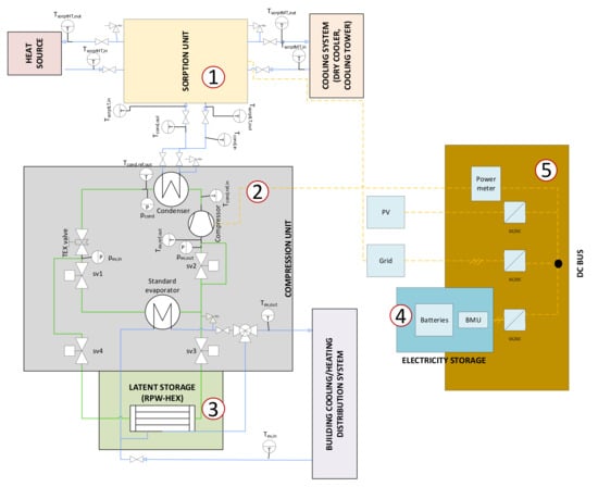
Figure 1.
Layout of the hybrid system, including the main sensors used and their names.
A picture of the installed system connected to the test stand at CNR ITAE is shown in Figure 2, where it is also possible to notice that the latent storage was insulated with 20 mm of mineral wool to avoid thermal dispersions towards the environment. Such a value was selected starting from the datasheet of the insulation material in order to guarantee that during a typical day–night cycle, i.e., using the storage after sundown, the temperature of the PCM is still within the phase change range.
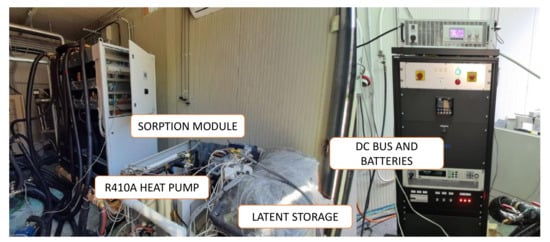
Figure 2.
HYBUILD system installed in the laboratory of CNR ITAE.
2.2. Operating Modes
The HYBUILD system here presented allows the provision of thermal energy with a high rate of self-consumption in residential buildings. It is specifically optimized for the installation in warm climates, where there is a high share of cooling demand over the year. Accordingly, the layout was chosen in order to maximize the energy efficiency for high ambient temperatures during summer. The following main operating modes were evaluated:
- Cooling mode 1—cooling through compression unit as stand-alone: in this case, the sorption module is not powered (i.e., due to a too low temperature of the heat source) and all the cooling demand is provided by the reversible heat pump, which works as a chiller. The standard evaporator of the heat pump (i.e., a plate heat exchanger is employed).
- Cooling mode 2—cooling through compression unit in cascade operation: in this operating mode, the sorption module is powered on and cools down the condenser HTF circuit of the reversible heat pump, which provides the required cooling demand to the user, using the standard evaporator.
- Cooling mode 3—discharge of the refrigerant PCM water—heat exchanger (RPW-HEX): in this case, both the sorption module and the reversible heat pump are turned off and all the cooling demand is supplied by discharging the latent storage.
- Cooling mode 4—parallel charge/discharge of the RPW-HEX through compression unit as stand-alone: this operating mode exploits the unique feature of the investigated system. The reversible heat pump is turned on and the pump on the RPW-HEX HTF circuit is operated as well. Accordingly, at each instant, the refrigerant and the HTF are circulated through the RPW-HEX, and while PCM is partially charged, a cooling effect is delivered to the user. This is particularly suitable for part load operation. To switch between the RPW-HEX and the standard evaporator, two piloted solenoid valves were installed on the refrigerant circuit, whereas a three-way piloted valve was installed in the HTF circuit.
- Cooling mode 5—parallel charge/discharge of the RPW-HEX in cascade operation: similar to the previous operating mode, the RPW-HEX is simultaneously charged and discharged, but the heat pump is operated in cascade mode.
- Charging mode 1—charging of the RPW-HEX through the compression unit in stand-alone operation: the pump on the HTF circuit of the RPW-HEX is turned off and all the evaporation heat is released on the PCM, that is charged. The reversible heat pump is operated as a stand-alone unit (sorption module is off).
Charging mode 2—charging of the RPW-HEX through the compression unit in cascade mode: it is similar to the previous operation, but in this case the sorption module is turned on and cascade connection is realized.
In addition, during winter, the reversible heat pump can provide heating by means of reversing the HTF circuits of the condenser and the evaporator. However, since no optimization on the components and layouts for this case was foreseen, this mode is not reported in the present investigation.
Regarding the operation of the electrical section, the following control logic is implemented: a range for the operation of the batteries, in terms of minimum and maximum allowed State Of Charge (SOC) is defined. Accordingly:
- if the SOC is higher than the minimum one and there is power request from the compressor of the heat pump, then the energy is supplied by the batteries;
- if the SOC is lower than the minimum one, the energy for the operation of the compressor of the pump is taken from the grid.
Moreover, if energy from PV is available, it is used primarily to operate the heat pump (in presence of cooling/heating demand) and secondarily to charge the batteries.
3. Methodology
3.1. Testing Facilities
A test stand already available at CNR-ITAE was used for testing, which is described in detail in [39]. It mainly consists of three storages, corresponding to the three thermal levels needed for the operation of the HYBUILD system. Heat source temperature is simulated by using two heaters, a gas heater and an electric one, connected to a 1.5 m3 storage. Ambient heat sink is simulated by means of an electric chiller connected to a 1 m3 storage, whereas heat source for evaporation is simulated by means of a 0.75 m3 storage with immersed thermal resistances. All the piping of the testing rig is insulated with polyurethane foam and aluminum external cover. Data acquisition and control are done through cDAQ National Instrument hardware and LabVIEW software. The DC bus controller was connected to the main electric grid of the laboratory, whereas PV generation was simulated by means of an ElektroAutomatic DC supply voltage that can be remotely controlled. The heat storage medium and heat transfer fluid of high temperature (HT) and medium temperature (MT) tanks and HT and MT circuits on the primary side of HEX1 and HEX2 was tap water, whereas the low temperature (LT) tank and the primary side of HEX3 are filled with 40% water/glycol mixture. The secondary side of HEX1, HEX2, and HEX3 is filled with a 10% water/glycol mixture with a corrosion inhibitor (Coracon HE6 (https://www.aqua-concept-gmbh.eu/de/service/ausschreibungstexte/, accessed on 30 April 2021)). An accurate temperature regulation in the various circuits was obtained by mixing supply and return streams through high-speed mixing valves on the primary side of HEX1, HEX2, and HEX3.
The following sensors are installed in the testing rig: Class A type T thermocouples (accuracy ±0.5 °C), magnetic flow meters (accuracy ±2.5% full scale).
For the testing of the HYBUILD system, additional sensors were installed in the proximity of inlet and outlet of all circuits, which were ultimately used for the evaluation of system performance. A list of the sensors and their accuracy is given in Table 1, whereas the layout of the testing rig is shown in Figure 3.

Table 1.
Sensors and their accuracy.
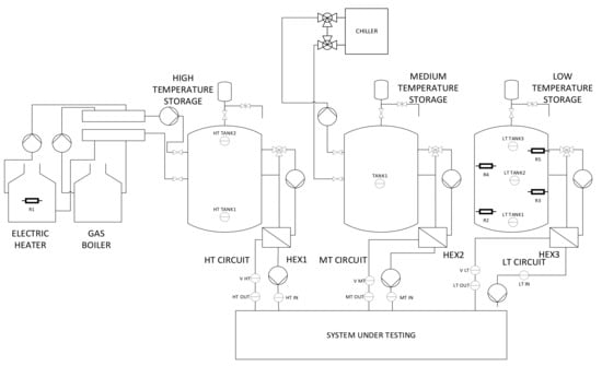
Figure 3.
Layout of the test stand at CNR and main sensors.
3.2. Data Collection and Testing Conditions
In order to estimate system performance, heat flows to each component were measured, and in particular the following quantities were used:
- Thermal power to the heat source circuit of the sorption chiller .
- Heat rejection power of the sorption chiller .
- Evaporation power of the sorption chiller .
- Condensation power of the vapor compression heat pump .
- Evaporation power of the vapor compression heat pump .
- Charge power of the PCM storage .
- Discharge power of the PCM storage .
- Electric energy input for the operation of the compressor of the heat pump .
- Auxiliary power for the sorption module, .
The instantaneous thermal power for each component were calculated as:
where is the instant power in kW, is the mass flow rate in the circuit in kg/s, cp is the specific heat capacity of the heat transfer fluid in kJ/kgK, and Tin and Tout are the inlet and outlet temperatures of the circuit considered.
Instead, all the electric power contributions were directly measured by means of the power meter integrated in the rack with DC bus.
In addition, the energy charged or discharged in the RPW-HEX was calculated as:
where [kJ] is the energy charged or discharged and ttest [s] is the overall duration of the test analyzed.
For the evaluation of the performance of the heat pump and the comparison of its operation in stand-alone the Energy Efficiency Ratio (EER) was calculated as:
The normalized cooling power is defined as the ratio between the cooling power of the compression unit at a certain condition and the cooling power in nominal conditions. The nominal conditions chosen are: operation with standard evaporator in compression-only mode (CM1), inlet temperature to the condenser of 32 °C, outlet temperature in the HTF circuit of the evaporator of 7 °C., flow rate in the HTF circuit of the condenser of 0.75 kg/s, and flow rate in the HTF circuit of the evaporator of 0.70 kg/s:
3.3. Uncertainty Analysis
Uncertainty analysis was carried out on the experimental values of thermal powers and EER, considering the uncertainty on mass flow, temperature, and electrical power measured. According to the extended uncertainty analysis, the uncertainty on thermal power was calculated as:
and were calculated for a triangular probability distribution as suggested by UNI CEI ENV 13005: . For the flow meter, “a” factor is indicated by technology provider and, in this case, is 2.5% of measured value:
For ∆T uncertainty, the value guaranteed for class A Pt100 was used: a = 0.1 °C:
Similarly, for EER uncertainty analysis:
With:
Considering the experimental results, the was estimated to be in the range of 2–4% and the in the range of 4–6%.
4. Test Results
In this section, the main results of tests will be shown. The section is organized as follows: at first (Section 4.1), the results of the operation of the system without the sorption module will be given, in terms of typical dynamic evolution. Subsequently, in Section 4.2, the results of cascade mode will be presented, again in terms of dynamic evolutions of the various parameters recorded. Section 4.3 presents an overall energy balance of the system to identify the relative flows and contributions of the components to the overall energy required and supplied by the system investigated. Finally, Section 4.4 presents the performance maps of the system for the various operating modes as a function of boundary temperatures in the different circuits.
4.1. Stand-Alone Compression Operation
A first series of tests was carried out as a benchmark, considering the different operating modes when the compression unit works as a stand-alone chiller. In order to better evaluate the energy charged/discharged and the uniformity in the temperature of the latent storage, 8 Pt100 sensors were installed, and their positions are shown in Figure 4. The typical temperature evolutions for reference tests are shown in Figure 5 (charging mode 1) and Figure 6 (cooling mode 3, discharge of the RPW-HEX). The curves for the cooling provision with the standard evaporator (cooling mode 1) are not reported since a continuous and steady-state operation was achieved during the whole test duration.
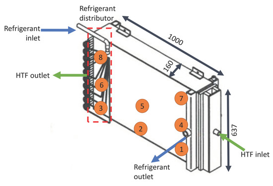
Figure 4.
3D view of the RPW-HEX and position of sensors and inlet/outlet ports.
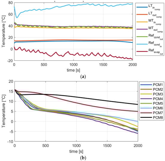
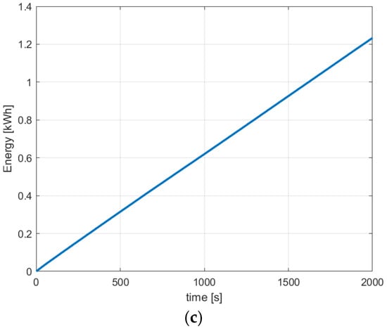
Figure 5.
Example of test results for charging mode 1. (a) Temperatures of HTF and refrigerant circuits of the RPW-HEX; (b) temperatures of the PCM; (c) energy supplied to the PCM during the test.
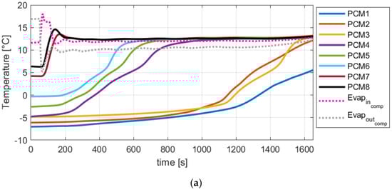
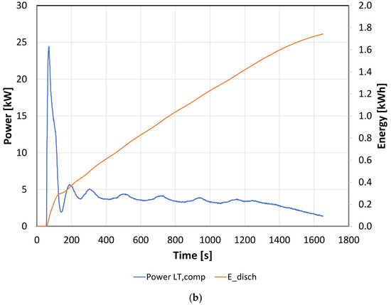
Figure 6.
Example of test results for cooling mode 3. (a) Temperatures of HTF and the PCM; (b) energy discharged during the test and correspondent power.
For the charging operation of the RPW-HEX, the main peculiarities identified were the extremely high temperature difference between the refrigerant at the compressor outlet and the evaporator outlet, which penalizes the operation of the system. The spikes in the temperature evolutions of the refrigerant were due to the operation of the thermostatic expansion valve. In order to better understand the temperature distribution in the RPW-HEX, the schematic of the latent storage and the positions of the sensors are shown in Figure 4. It was possible to notice that, during charge of the RPW-HEX, the areas close to the refrigerant outlet (PCM4, PCM5) were the coldest one. Moreover, there was a stratification in the vertical direction, with the upper part of the HEX (PCM7, PCM8) at a significantly higher temperature than the remaining part of the HEX, up to 15 K at the end of the charging period considered. Indeed, while in the lower and central areas of the RPW-HEX, the stratification was not so evident (about 3K in the phase change range), the difference to the upper part of the latent storage was higher. The reasons for this behavior were different: on the one end, the refrigerant circuit was designed in order that part of the expansion occurs in the thermostatic expansion valve and part directly in the refrigerant distributor shown in Figure 4. However, since the design of the system was carried out considering the retrofitting of the heat pump, the large inlet refrigerant pip did not force the refrigerant to enter the passages homogenously. Accordingly, each refrigerant passage was connected individually with copper tubes and a special distributor to generate more pressure loss in each passage. Due to the effect of gravity and of the low thermal conductivity of paraffin, such a design could not prevent the stratification. Preliminary evaluations in lab-scale shows that with a vertical arrangement of the RPW-HEX, such a problem could be avoided. From the temperature evolution in Figure 5b, it is possible to notice that phase change occurs in the temperature range 2–7 °C, whereas Figure 1c shows that a linear trend for the energy supplied can be identified.
The considerations reported above for the charge apply also to the case of the discharge of the RPW-HEX (cooling mode 3), shown in Figure 6 for the case of HTF flow rate of 0.5 kg/s and HTF inlet of 12 °C. It is possible to notice an even more marked stratification than during discharge. The upper part of the RPW-HEX, where phase change was not completed, reaches in less than 200 s the temperature of the HTF, thus completing the solidification. The effect of vertical stratification is clear, since the phase change in the central part of the RPW-HEX (sensors PCM4, PCM5, PCM6) occurs while the lower part of the RPW-HEX (sensors PCM1, PCM2, PCM3) are still at a temperature between −7 and −5 °C. The main reason for such a behavior is the low thermal conductivity of the PCM chosen, and therefore, the farthest areas from the HTF inlet/outlet ports experience a slow dynamic behavior. The power measured in the HTF circuit is shown in Figure 6b: at the beginning of the discharge there was a peak of 25 kW due to the high temperature different between the HTF entering and the PCM. After about 200 s, a value of 4 kW was reached, which was maintained constantly until almost the end of discharge, i.e., 1400 s approx. The energy discharged is plotted in Figure 6b as well: similar to the charging process, a linear behavior is observed and up to 1.7 kWh were discharged under the examined operating boundaries.
Figure 7 shows what occurs during a test in cooling mode 4, i.e., with parallel charge/discharge of the RPW-HEX under the following conditions: MTcomp,in = 35 °C, LTcomp,out: 5 °C, flow rate of LTcomp 0.72 kg/s. During this operation, peculiar of the design chosen, once the PCM reaches the phase change temperature, steady conditions are achieved and, at each instant, part of the evaporation heat keeps the PCM in the liquid state, whereas part is used for the evaporation of the refrigerant and the subsequent cooling effect to the user. For this cooling mode, the stratification in the PCM is less marked, i.e., 2.5 K between the colder and warmer points are measured, thus remarking that an improved behavior can be achieved under these conditions, that were specifically targeted during design phase.
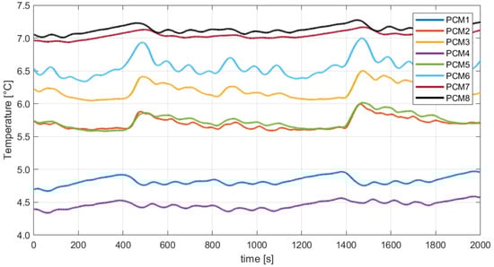
Figure 7.
Temperatures in the PCM for a test with parallel charge/discharge (cooling mode 4) of the RPW-HEX.
4.2. Cascade Operation
One of the main characteristic features of the HYBUILD system here presented is the optimization for summer operation by coupling the sorption module and the compression unit in cascade to reduce the temperature lift on the compression unit. A more complete discussion of the results when comparing, for typical ambient temperatures, the two operations, will be given in Section 5. In this section, the typical results are reported and the peculiarities of the cooling mode 2, charging mode 2, and cooling mode 5 are discussed.
Figure 8 shows the temporal evolutions of temperatures for a test in cooling mode 2, i.e., in cascade operation of the sorption unit and the compression unit working with the standard evaporator. In particular, Figure 8a shows the main temperatures in the different circuits of the sorption and compression units. The MTin and MTout temperatures for the compression unit are not reported, since they correspond to the LTout,sorp and LTin,sorp ones, respectively. The main peculiarity of cascade operation is the possibility to keep the precision in the regulation of the temperature supplied to the user with varying conditions, while reducing the temperature lift on the compression unit [42]. Indeed, it is possible to see that that LTin,comp and LTout,comp are constant throughout the duration of the test, despite the typical discontinuous behavior of the sorption module. At the same time, there is a clear reduction in the condensation circuits (refrigerant and HTF) of the compression unit, since more than 12 K of temperature reduction compared to the return temperature from the cooling system (i.e., MTin,sorp-MTin,comp) can be achieved.
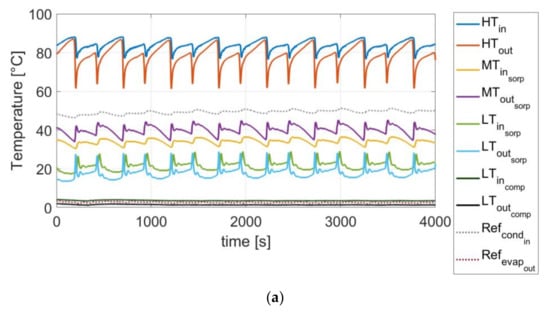
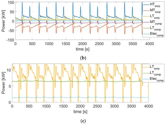
Figure 8.
Example of test results for cooling mode 2. (a) Temperatures of HTF and R410a for sorption and compression units; (b) power measured in the HTF circuits and electricity consumption of the compressor; (c) detail of powers for the LT circuits of sorption and compression unit and electricity consumption of the compressor.
Figure 8b,c show the power evolutions for the same test. The powers on the negative y axis are those released in the ambient, whereas on the y axis the absorbed powers are indicated. During the phase switch of the sorption unit, extremely high thermal powers in the HT and MT circuits of the sorption unit are measured, due to the need to heat up one adsorber from the adsorption to the desorption temperature levels and vice versa for the other. However, as clearly represented in Figure 8c, this does not significantly affect the operation on the power supplied to the user (LTcomp). Moreover, it is also possible to see that, with the exception of some seconds during the phase switch, the power supplied by the sorption unit to cool down the condenser of the compression unit was always higher than 6 kW.
Figure 9 instead presents the results of a typical test for charging mode 2, i.e., when all the evaporation heat of the compression unit is supplied to the PCM. Compared to the temperature evolutions that are reported in Figure 5, the temperature of the refrigerant at the exit of the compressor was much lower (up to 35 K) and only increased by 4 K during the charge, whereas up to 16 K of increase were measured for charging mode 1. The same stratification of PCM as in the previous case was identified. Figure 9c presents the energy supplied during the charge where the small peaks corresponding to the phase switch of the sorption module can be seen.
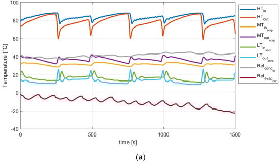
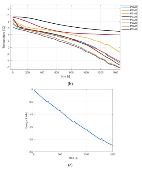
Figure 9.
Example of test results for charging mode 2. (a) Temperatures of HTF and R410a; (b) temperatures of PCM; (c) energy supplied during the test.
Figure 10 demonstrates the operation of the HYBUILD cascade configuration under the cooling mode 5, i.e., the parallel charge/discharge of the RPW-HEX. The system is operated so that LTout,comp is in the range of 5 °C, to allow part of the PCM to be in the phase change range. As already shown in Figure 7, the stratification of PCM in this case is reduced compared to the charging mode (<3 K). At the same time, the temperatures of the refrigerant circuit are comparable with those measured for cooling mode 2 (Figure 8) under the same MTin,sorp. Similarly, the temperature in the LT circuit of the sorption unit (and therefore the MT circuit of the compression unit) is the same as for the cooling mode 2, thus remarking that the innovative operation of the presented system not only does not penalize overall operation but gives the additional possibility of partially charging the storage to further increase the self-consumption rate. A comparison between the different cooling modes, in terms of energy efficiency, will be given in Section 5.1 and Section 5.2.
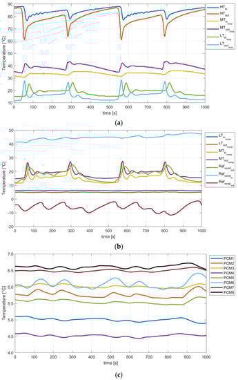
Figure 10.
Example of test results for cooling mode 5. (a) Temperatures of HTF in the sorption unit; (b) temperatures of HTF and R410a in the compression unit; (c) temperatures of PCM.
4.3. Energy Balance of the Hybrid System
In order to better understand the performance of the hybrid system proposed, the relative contributions of the different energy inputs under the five cooling modes (CMs) tested are reported in Figure 11. The contributions considered are only the heat or electricity inputs supplied to the system. The same boundary conditions were chosen for comparison purposes: MTin,sorp (for CM2 and CM5) or MTin,comp (for CM1 and CM4) of 33 °C, HTin of 85 °C (for CM2 and CM5), LTout,comp 5 °C. Comparing CM1 and CM4, it is possible to notice that about 1/3 of the overall evaporation heat was released to the PCM during parallel charge/discharge, whereas the relative contribution of the electricity consumption was the same. Comparing CM2 and CM5, the same result can be seen, i.e., that the only relevant difference between the two cases is that 2/3 out of the overall useful cooling effect are actually supplied to the user and the remaining part of evaporation heat is supplied to the PCM. In the case of CM3, the only contribution is the one of the PCM, since it is the only source for supplying the user with the desired cooling effect. The analysis also allows identifying the efficiencies of the system, which will be further discussed in the next section. In general, a ratio of 3:1 for the heat source input to the cooling effect delivered to the user can be achieved under these conditions, whereas the electrical efficiency of the compression unit is higher than 3.
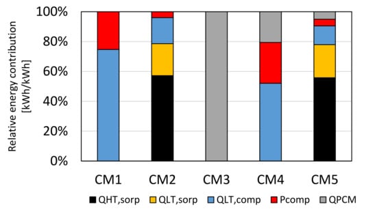
Figure 11.
Relative energy contributions to the overall energy inputs of HYBUILD system for different Cooling Modes (CMs).
4.4. Temperature Lift
As previously stated, the main reason for selecting a cascade layout was the reduction of the temperature lift for the operation of the compression unit. A comparison between the compression unit stand-alone operation (CM1, CM4, ChM1) and the cascade operation (CM2, CM5, Charging mode 2, ChM2) is reported in Figure 12. The temperature on the x axis was the inlet temperature of the HTF either to the compression unit (CM1, CM4, ChM1) or the sorption unit (CM2, CM5, ChM2) and corresponded to the return temperature from the cooling system (dry cooler, wet tower, etc.). It is possible to notice that a linear trend for both cascade and compression stand-alone operation was measured, with an average ΔT of 16 K, which represents a significant reduction that was kept also for higher temperatures, i.e., >35 °C.
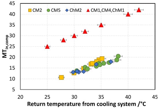
Figure 12.
Variation of temperature of HTF in the compression unit with external temperature for different operating modes. For all the reported tests, LTout,comp = 5 °C.
The effect on the operation of the compression unit can be seen by reporting the operating cycle of the reversible heat pump in a p-h diagram. Accordingly, two reference ideal cycles are plotted in Figure 13. The two cycles in red and dark green represent the reference cycles for CM1 operation with evaporation temperature of the refrigerant of 2 °C and condensation temperature of 30 °C (dark green) and 35 °C (red line). The correspondent operating cycles for cascade operation are the light green one (with condensation temperature of 14 °C) and brown (with condensation of 17 °C). It is possible to notice that there is a significant reduction of the operating pressure for the system, i.e., , which is a marked decrease compared to the ones measured or evaluated in similar systems in the literature [29,39]. As discussed, such a pressure ratio (PR) is constant for the overall operating field investigated, i.e., 20–42 °C of return temperature from the cooling system and can then be used for sizing and evaluation purposes.
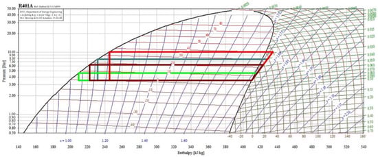
Figure 13.
Compression cycles for CM1 and CM2 operation.
5. Discussion
The aim of this section is to critically discuss the results presented previously. A first elaboration is presented in Section 5.1, where the EER is calculated for the different conditions and operating modes, including the evaluation according to Eurovent conditions, for the seasonal EER (Section 5.2). In Section 5.3, the system is compared to other hybrid and innovative heating/cooling systems already discussed in the open literature, to highlight the similarities, benefits and disadvantages of the investigated system. Finally, Section 5.4 presents a case study under typical operating conditions, considering the load profiles for three weeks in a reference building to evaluate the energy flows between the various components under dynamic operation.
5.1. EER
A first evaluation of the results can be done in terms of EER, i.e., the ratio between the useful effect over the electricity consumed. The EER for the different cooling modes is presented in Figure 14 as a function of return temperature from cooling system, allowing a comparison not only between the cascade and compression stand-alone operations, but also to evaluate the standard evaporator and RPW-HEX operation. In order to allow a comparison for the operating modes, all the tests considered were done with LTout,comp of 5 °C and all the tests including the sorption module were done for HTin of 85 °C. The baseline for operation was the CM1 (yellow rhombuses in Figure 14). For the range of interest of the system operation, the EER of the reference system (the compression unit working as stand-alone with the standard evaporator), EER was between 3 and 4. When operating in cascade mode with the standard evaporator (CM2, green circles) the EER in the same temperature range was between 4.5 and 5.5, hence with an increase of 50% compared to the benchmarking case. The EER in CM4 and CM5, i.e., when parallel operation of the RPW-HEX was chosen, was lower, due to the fact that only part of the cooling effect was supplied to the user, since part of it was used to charge the PCM. What was interesting to notice is that, for CM4 (orange triangles), the EER achieved are indeed quite low (2.9 to 1.5 going from 21 to 39 °C), but the cascade operation (CM5, blue stars) allows operating with the same efficiency as the standard operation (CM1), while achieving an extra benefit for overall self-consumption, i.e., the partial charge of the PCM. However, as already discussed in the previous section, under CM4 and CM5, the cooling power supplied to the user was lower than in CM1 and CM2. This is highlighted in Figure 15, where the normalized cooling power for the different operating modes was reported. It was possible to notice that for CM1 and CM2, the normalized cooling power was in the range of 1.1 to 0.8 for a range of return temperatures from the cooling system of 23 to 40 °C. The cooling power in CM2 was slightly higher than in CM1, due to the lower temperature lift in the same external conditions. As already stated in Section 4.3, 50 to 60% of nominal cooling power was instead delivered to the user in CM4 and CM5, with a lower penalization for CM5 compared to CM4.
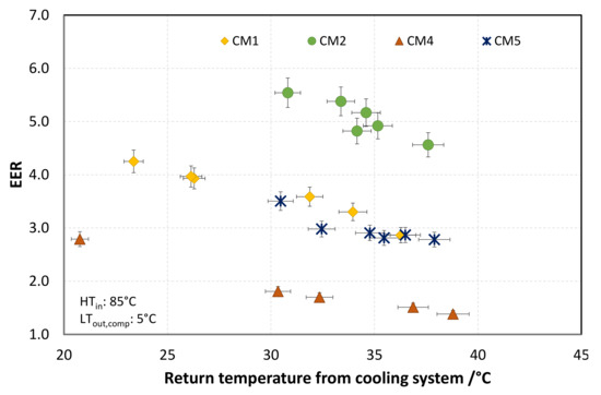
Figure 14.
EER for different cooling modes.
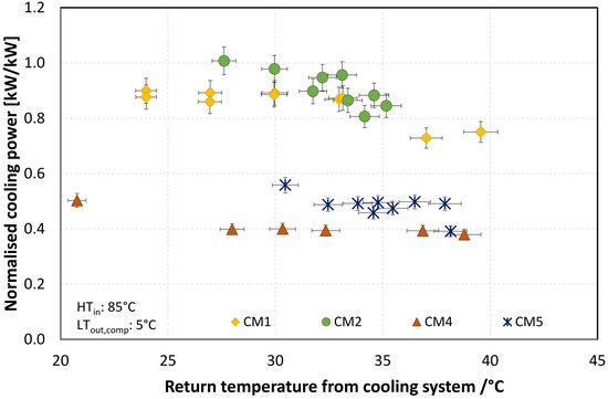
Figure 15.
Normalized cooling power for different cooling modes.
The EER for the charging modes is instead reported in Figure 16. ChM1 refers to the charging of the PCM with the compression unit in stand-alone mode, whereas ChM2 to the cascade operation. As for the case of cooling modes, a significant effect of cascade operation was observed, that increased with the return temperature from the cooling system. For instance, while at 30 °C, the EER gained in passing from compression to cascade operation by about 30%, for 37 °C it was up to 100%. The effect during charging tests was more marked than in cooling modes, since during charging, the temperature lift was higher, due to the lower pressure on the evaporator side because of the progressive reduction of PCM temperature.
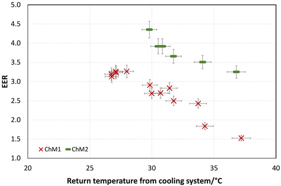
Figure 16.
EER for different charging modes.
5.2. European Seasonal Energy Efficiency Ratio
The results achieved under cascade operation (CM2) were analyzed in terms of European Seasonal Energy Efficiency Ratio (SEER), that allowed a better measure of the annual energy consumption and efficiency in typical day-to-day use [43]. It is calculated as a weighted average of EERs over a range of rated outdoor air conditions [44]:
where EER100, EER74, EER47, and EER21 are the EER of the unit at different partial cooling loads measured for the outdoor air temperatures of 35, 30, 25, and 20 °C, respectively, and an outlet temperature of the evaporator of 7 °C. Such calculation gives a more reliable evaluation of the overall efficiency of the heat pump over an entire cooling season, since it considers that full load conditions will only be needed for a reduced number of hours compared to the intermediate part load conditions.
For the current system, the SEER under CM1 was 3.9, whereas for CM2 it was 6.4, thus with an overall gain of 40%.
However, it is worth noticing that recent research has highlighted how the use of typical weather conditions, which are the basis for the selection of part load conditions of European SEER, can underestimate the cooling demand increase due to climate change up to 18% [45]. Accordingly, the gain in the EER at higher external temperature is, in perspective, even more interesting for future applications in warm climates.
5.3. Comparison with Previous Studies
The achieved results were compared with other literature studies of hybrid absorption-compression and adsorption-compression systems. It is worth remarking that the vast majority of studies in the literature are based on thermodynamic or numerical analyses, especially for the case of absorption-compression cascade units and therefore a fair comparison is not straightforward. The systems to be compared were chosen in order to guarantee similar operating conditions as the one here discussed.
Jain et al. [46] discussed the cascade configuration for a hybrid sorption-compression cycle with R410A as refrigeration of the compression stage and H2O–LiBr as working pair of the sorption stage. A numerical analysis for energy and exergy optimization was carried out and the results indicate a reduction in the compressor consumption of about 76% for 27 °C inlet temperature of water at the condenser of the sorption stage, 5 °C outlet at the evaporator of the compression stage, and 100 °C of heat source temperature. Under the same conditions, the current prototype yields an increase in EER of about 40% for CM1 and 90% for CM5.
In [47], a numerical analysis on a LiBr-H2O/R134a cascade system driven by solar radiation is presented. According to operating conditions (i.e., heat source temperature and ambient temperature), a COP (Coefficient of Performance) of 6.1 was reached with 35 °C ambient temperature and chilled water supply temperature of 7 ℃, with 50% electric power reduction as compared with the normal mechanical compression system. Such results are comparable with the ones obtained for the present prototype.
Some experimental studies are instead available for the coupling of solid adsorption-compression cascade systems, under conditions that are similar to the ones evaluated in the experiments here presented. For instance, in [42], the cascade combination of a R410a unit with a silica-gel water sorption one is investigated for air conditioning applications. The measured EER for an inlet temperature at the condenser of the sorption unit and 7 °C chilled water outlet temperature of the compression unit is in line with those measured in the current case, i.e., about 6, with an increase of 100% compared to the operation of the compression unit itself. It is however worth noticing that the tested system does not have the same flexibility as the one here evaluated, which includes the possibility of increasing the self-consumption through the use of the PCM.
In [48], a two-stage silica gel-water/CO2 sorption-compression system was experimentally assessed under Polish weather conditions. For air conditioning applications, the reduction of electric energy consumption by the cascade, with respect to the compression stand-alone unit, was higher than 30%, which was a bit lower than what measured for the present prototype in lab-controlled conditions.
These results further remark the promising features of the current system that can operate at the top energy efficiency compared to state-of-art hybrid systems at lab stage, while at the same time providing innovative operating modes.
5.4. Energy Evaluation under Typical Mediterranean Conditions
A set of tests was carried out simulating the PV production and the increasing ambient temperature for a reference day (21 July) in Madrid through the testing bench. In this way, the overall integration of the thermal and electric storage could be assessed, as well as the operational logic for the electric storage.
An example of test results is reported in Figure 17, in terms of the state of charge (SOC) of the batteries, which is limited between a lower threshold (28%) and an upper threshold (85%), as well as the energy charged and discharged for the batteries, the PV production and the energy required by the compressor of the heat pump. A positive value for the current of the batteries indicates their charging, whereas a negative value corresponds to the discharging of the battery. It is possible to notice that the batteries are charged within the first hours of the day and are discharged after sunset, allowing to extend the operating hours of the system without needing an external grid.
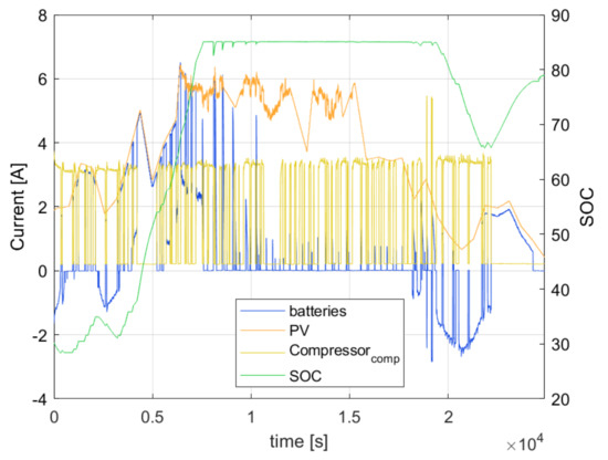
Figure 17.
Experimental results for a reference day in Madrid.
Starting from the experimental results described so far, a further evaluation was performed, to estimate to which extent the hybrid system here presented can self-sustain the cooling demand of a reference building for the climate of Athens. To this aim, the results of a set of TRNSYS simulations described in detail in [49] were used. From the simulations, which were used for an energy assessment of the heat pump and latent storage HYBUILD subsystem, the data on PV production, energy charged in the batteries and cooling load for three reference weeks were taken: 7–14 June, 21–28 July, 28 August–4 September. In addition, the data for the production of the Fresnel solar collectors that will represent the heat source for the HYBUILD system in the pilot site, provided by the producer, were used to evaluate the amount of energy available to drive the sorption module. Finally, to evaluate the efficiency of the hybrid sorption module-compression unit-latent storage system here presented, the performance maps for each operating mode were derived, as presented in Section 5.1, and the EER expected for each operating mode and each hour of the weeks evaluated, were calculated. In order to define the operating mode for each case, simplified control rules were used:
- The sorption module is operated only when there is a cooling demand and, at the same time, the output from solar collectors is enough to drive it and to cover the whole energy demand.
- Each time the sorption module is activated, the chosen operating mode between standard evaporator and parallel operation (i.e., CM2 or CM5) is those with the higher EER for the current ambient conditions.
- When there is a cooling demand and the sorption module cannot be operated, the compression unit is operated, working as a stand-alone unit. The chosen operating mode between standard evaporator and parallel operation (i.e., CM1 or CM4) is those with the higher EER for the current ambient conditions.
- During the first hours after sunset, the cooling demand is met by the latent storage until its full capacity is reached (and so the storage is completely discharged).
The results of this simplified evaluations are presented in the Sankey diagrams of Figure 18. During the week in June (Figure 18a), where the cooling demand is limited, not only the system was fully self-sufficient, but there was also excess heat available in the buffer, e.g., for DHW, and there was excess electricity that is not needed for the cooling system, but can be exploited for other household appliances. The efficiency of solar thermal collectors is about 40% and the cooling demand supplied to the user comes for about 1/6th from the PCM storage and for the remaining part from the standard evaporator. The compression unit works for about 70% of the time in cascade mode.
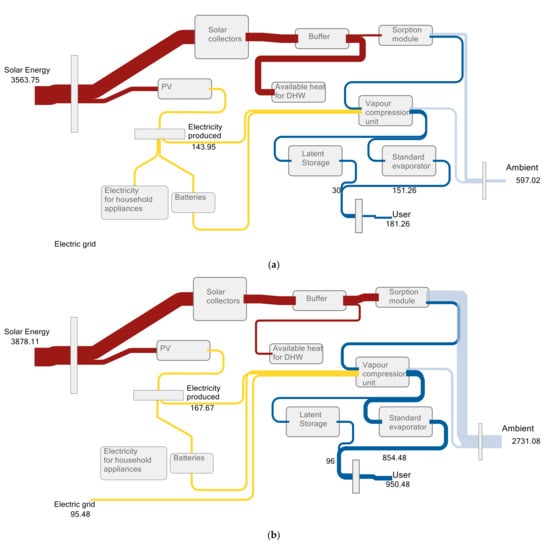
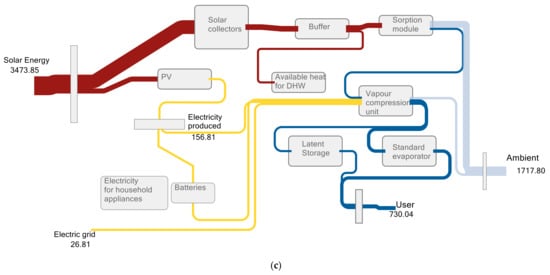
Figure 18.
Sankey diagrams for three reference weeks in the climate of Athens: (a) 7–14 June, (b) 21–28 June, (c) 28 August–4 September. All the flows are in kWh.
For the case of July (Figure 18b) chosen as an example of high cooling demand and high solar availability, 68% of electricity needed to drive the system came from the self-production from PV, either directly used for the heat pump or stored in the batteries for use after sunset, and the remaining 32% came from the grid. The cooling demanded the user is mostly covered through the standard evaporator and about 1/10th was supplied through the PCM. This was mostly due to the simplified operational logic imposed, whereas the latent storage could be better exploited through specific control strategies [50]. The sorption module was activated approximately for 65% of the hours, during which there was a cooling demand, whereas the remaining ones were covered by the compression unit. It is worth pointing out that for this week, the amount of excess heat stored in the buffer was sensibly lower than in the previous case, indicating that a good sizing for the peak load was achieved.
The third week chosen in the analysis, at the end of August, corresponded to a balanced case in which there was a moderate cooling demand and, at the same time, there was a good availability of solar for both PV and thermal collectors. As shown in Figure 18c, in this case the need for integration from the grid was only for 14% of the overall energy needed to drive the system, thus indicating a self-sufficiency level extremely high under still challenging ambient conditions. About 20% of the overall energy supplied to the user comes from the latent storage and the remaining from the standard evaporator. Operation under cascade mode (either CM2 or CM5) occurs for about 60% of the cooling demand period. As already stated, a proper control system could further increase this value.
The results of this simplified analysis clearly indicate that the system investigated is able to operate with high efficiency and, at the same time, keeping a high level of self-consumption and reducing the need for integration from the grid. Through further optimization, a scenario for the application in passive buildings disconnected from the grid could be then foreseen. Such results will be validated in a pilot site in Almatret (Spain), where an adapted control logic based on different optimization rules will also be investigated.
6. Conclusions
In the present paper, the results on a testing campaign in lab-controlled conditions of a hybrid system for residential applications are reported. The system combined a hybrid sorption-compression heat pump in cascade configuration, a three-fluids heat exchanger with a PCM embedded in the compression unit of the cascade heat pump, and a DC-bus that included PV connection and electricity storage (batteries). The system was optimized for operation under warm climates and the results of different cooling modes and charging modes of the storage are presented. Focus of the experimental analysis was two-fold: proving the long-term steady operation of the system under the different modes and evaluating its energetic performance in the different cases.
The results of measurement proved that, for cascade operation, EER of 7 to 4 can be achieved according to external temperatures, whereas for traditional operation of the compression unit as a stand-alone one, it ranged from 2.5 to 4. The most innovative feature of the hybrid unit was the possibility to exploit part load operation for simultaneous charge/discharge of the PCM storage, i.e., only part of the energy was supplied to the user to satisfy the cooling demand and the remaining part was used to charge the PCM to extend operating hours. The energy efficiency under this operating mode, when cascade configuration is used, allows maintaining at least the same efficiency as the reference compression heat pump.
For comparison purposes, an equivalent seasonal EER was calculated according to the procedure commonly employed for air-conditioning units, showing an increase of up to 60% compared to the compression unit only.
Finally, the performance maps obtained in the experimental campaign were combined with the simulation results for a typical residential case under Athens climatic conditions and the energy flows between the various components were calculated. It was found that up to 100% of the electricity needed to drive the system could be self-produced for a modest cooling demand and up to 67% for the warmer conditions with high cooling demand. Under non-optimized control, the cascade operation was active for 60 to 70% of the cooling demand period and up to 20% of the overall energy to the user can be delivered by exploiting the PCM storage.
The tested system will be installed in a pilot site in Almatret (Spain) and the results under real operating conditions for a reference season will be monitored, to validate the laboratory testing and further advance the application of the hybrid system in residential applications for highly efficient buildings. On-going activities are aimed at the evaluation of the life cycle impact and costs of the system. The main advantage of the proposed configuration is the strong reduction of the costs related to the operational stage even though the higher complexity of the system reflects on a higher capital cost. However, given the recent boost from several governments to energy efficiency improvement in building with subsidies, the economic feasibility of the system can be achieved.
The system here presented was designed for the application in Mediterranean climates, where cooling demand represents the main load during the year and the condition under which it is more critical to keep comfort conditions. The flexibility of the system allows the operation also in heating-driven climates since the heat pump that represents the core of the system is a reversible one. However, for proper optimization in different climates, with heating demand as primary load, the use of a different PCM could be foreseen, i.e., to make the heat pump work as a solar-assisted system matching it with the expected outlet from solar collectors or by embedding the latent storage in the condenser of the heat pump.
Author Contributions
Development of sorption module A.G., R.H., A.F. and V.P.; development and preliminary testing of heat pump: E.V. and N.B.; development and preliminary testing of latent storage: D.V., G.Z., B.N. and A.S.; development and preliminary testing of DC bus and electric storage: N.K., D.A., G.B. and F.S.; Testing of complete system: V.P., G.B., A.B. and G.E.D.; visualization and data curation: V.P., A.B. and G.B., writing—original draft preparation, V.P.; writing—review and editing, A.F., N.K., G.Z. and L.F.C.; supervision and project administration, A.F., L.F.C. and S.K. All authors have read and agreed to the published version of the manuscript.
Funding
This project has received funding from the European Union’s Horizon 2020 research and innovation program under grant agreement No. 768824 (HYBUILD). This work was partially funded by the Ministerio de Ciencia, Innovación y Universidades de España (RTI2018-093849-B-C31) and by the Ministerio de Ciencia, Innovación y Universidades—Agencia Estatal de Investigación (AEI) (RED2018-102431-T). GREiA is certified agent TECNIO in the category of technology developers from the Government of Catalonia. This work is partially supported by ICREA under the ICREA Academia program.
Institutional Review Board Statement
Not applicable.
Informed Consent Statement
Not applicable.
Data Availability Statement
Not applicable.
Conflicts of Interest
The authors declare no conflict of interest.
Nomenclature
| cp | specific heat, J/(kg K) |
| E | Electric energy, J |
| f | frequency, Hz |
| mass flow rate, kg/s | |
| P | Electric Power, W |
| p | Pressure, bar |
| Q | Thermal Energy, J |
| Thermal Power, W | |
| T | Temperature, °C |
| t | time, s |
| Acronym | |
| EER | Energy Efficiency Ratio |
| HEX | Heat EXchanger |
| HT | High Temperature |
| HTF | Heat Transfer Fluid |
| LT | Low Temperature |
| MT | Medium Temperature |
| PCM | Phase Change Material |
| PV | Photovoltaic |
| RPW | Refrigerant-PCM-Water |
| SOC | State of Charge |
| Subscripts | |
| ch | charge |
| comp | compressor |
| cond | condenser |
| disch | discharge |
| el | electric |
| evap | evaporator |
| in | inlet |
| out | outlet |
| sorp | sorption |
Appendix A. System Specifications
In the present appendix, the main characteristics of the different components of the system are reported.
Table A1.
Sorption module.
Table A1.
Sorption module.
| Working Pair | Zeolite/Water |
| Adsorbers | Aluminium finned flat tubes heat exchangers connected in parallel for each adsorber with directly syinthesized zeolite (https://fahrenheit.cool/en/references/zeolite-crystallization-technology/ (accessed on 30 April 2021)) |
| Nominal cooling power | 14 kW |
| Nominal electricity consumption of auxiliaries (pumps in all hydraulic circuits) | 1 kW |
Table A2.
Compression heat pump.
Table A2.
Compression heat pump.
| Refrigerant | R410a |
| Compressor rotation range in % | 30–100% |
| Nominal cooling power in kW | 13 |
Table A3.
Three-fluid heat exchanger for latent storage-.
Table A3.
Three-fluid heat exchanger for latent storage-.
| Parameter | Refrigerant | Coolant | PCM (RT4) (https://www.rubitherm.eu/en/index.php/productcategory/organische-pcm-rt, (accessed on 30 April 2021)) |
| Number of passages | 20 | 20 | 42 |
| Fin # | 73 | 18 | 33 |
| Fluid volume in L | 5.34 | 4.6 | 46 |
| Core length × width × depth in mm | 1000 × 585 × 160 | ||
| Empty weight in kg (Al) | 190 | ||
Table A4.
ELECTRICITY STORAGE.
Table A4.
ELECTRICITY STORAGE.
| Type of Battery | Lithium Titanate Oxide |
|---|---|
| Nominal capacity/module | 1 kWh |
| Number of modules | 3 |
References
- Garcia, J.; Kranzl, L. Ambition Levels of Nearly Zero Energy Buildings (nZEB) Definitions: An Approach for Cross-Country Comparison. Buildings 2018, 8, 143. [Google Scholar] [CrossRef]
- Akeiber, H.; Nejat, P.; Majid, M.Z.A.; Wahid, M.A.; Jomehzadeh, F.; Zeynali Famileh, I.; Calautit, J.K.; Hughes, B.R.; Zaki, S.A. A review on phase change material (PCM) for sustainable passive cooling in building envelopes. Renew. Sustain. Energy Rev. 2016, 60, 1470–1497. [Google Scholar] [CrossRef]
- Guerrero, M.; Sánchez, J.; Álvarez, S.; Tenorio, J.A.; Cabeza, L.F.; Bartolomé, C.; Pavón, M. Evaluation of the behavior of an innovative thermally activated building system (TABS) with PCM for an efficient design. E3S Web Conf. 2019, 111, 03043. [Google Scholar] [CrossRef]
- Stropnik, R.; Koželj, R.; Zavrl, E.; Stritih, U. Improved thermal energy storage for nearly zero energy buildings with PCM integration. Sol. Energy 2019, 190, 420–426. [Google Scholar] [CrossRef]
- De Gracia, A. Dynamic building envelope with PCM for cooling purposes—Proof of concept. Appl. Energy 2019, 235, 1245–1253. [Google Scholar] [CrossRef]
- Piselli, C.; Prabhakar, M.; de Gracia, A.; Saffari, M.; Pisello, A.L.; Cabeza, L.F. Optimal control of natural ventilation as passive cooling strategy for improving the energy performance of building envelope with PCM integration. Renew. Energy 2020, 162, 171–181. [Google Scholar] [CrossRef]
- Navarro, L.; Gracia, A.; de Castell, A.; Cabeza, L.F. Experimental study of an active slab with PCM coupled to a solar air collector for heating purposes. Energy Build. 2016, 128, 12–21. [Google Scholar] [CrossRef]
- Badiei, A.; Golizadeh Akhlaghi, Y.; Zhao, X.; Shittu, S.; Xiao, X.; Li, J.; Fan, Y.; Li, G. A chronological review of advances in solar assisted heat pump technology in 21st century. Renew. Sustain. Energy Rev. 2020, 132, 110132. [Google Scholar] [CrossRef]
- Montagnino, F.M. Solar cooling technologies. Design, application and performance of existing projects. Sol. Energy 2017. [Google Scholar] [CrossRef]
- Palomba, V.; Dino, G.E.; Frazzica, A. Solar-Assisted Heat Pumps and Chillers. In Handbook of Climate Change Mitigation and Adaptation; Springer: New York, NY, USA, 2021; pp. 1–54. [Google Scholar]
- Palomba, V.; Dino, G.E.; Frazzica, A. Coupling Sorption and Compression Chillers in Hybrid Cascade Layout for Efficient Exploitation of Renewables: Sizing, Design and Optimization. Renew. Energy 2020, 154, 11–28. [Google Scholar] [CrossRef]
- Palomba, V.; Borri, E.; Charalampidis, A.; Frazzica, A.; Karellas, S.; Cabeza, L.F. An Innovative Solar-Biomass Energy System to Increase the Share of Renewables in Office Buildings. Energies 2021, 14, 914. [Google Scholar] [CrossRef]
- Fan, Y.; Zhao, X.; Li, J.; Li, G.; Myers, S.; Cheng, Y.; Badiei, A.; Yu, M.; Golizadeh Akhlaghi, Y.; Shittu, S.; et al. Economic and environmental analysis of a novel rural house heating and cooling system using a solar-assisted vapour injection heat pump. Appl. Energy 2020, 275, 115323. [Google Scholar] [CrossRef]
- Neyer, D.; Ostheimer, M.; Dipasquale, C.; Köll, R. Technical and economic assessment of solar heating and cooling—Methodology and examples of IEA SHC Task 53. Sol. Energy 2018, 172, 90–101. [Google Scholar] [CrossRef]
- Shao, N.; Ma, L.; Zhang, J. Experimental study on electrical and thermal performance and heat transfer characteristic of PV/T roof in summer. Appl. Therm. Eng. 2019, 162, 114276. [Google Scholar] [CrossRef]
- Zhang, Q.; Yang, Z.; Li, N.; Feng, R.; Shi, P. A novel solar photovoltaic/thermal assisted gas engine driven energy storage heat pump system (SESGEHPs) and its performance analysis. Energy Convers. Manag. 2019, 184, 301–314. [Google Scholar] [CrossRef]
- Cai, J.; Ji, J.; Wang, Y.; Huang, W. Numerical simulation and experimental validation of indirect expansion solar-assisted multi-functional heat pump. Renew. Energy 2016, 93, 280–290. [Google Scholar] [CrossRef]
- Zhang, P.; Rong, X.; Yang, X.; Zhang, D. Design and performance simulation of a novel hybrid PV/T-air dual source heat pump system based on a three-fluid heat exchanger. Sol. Energy 2019, 191, 505–517. [Google Scholar] [CrossRef]
- Guo, Z.J.; Shao, J.; Li, X.H.; Liu, R.J.; Wang, W.; Tian, X.L. Application of pump-assisted separate heat pipe on dehumidifying enhancement in air conditioning system. Appl. Therm. Eng. 2016, 98, 374–379. [Google Scholar] [CrossRef]
- Bae, S.; Nam, Y.; da Cunha, I. Economic Solution of the Tri-Generation System Using Photovoltaic-Thermal and Ground Source Heat Pump for Zero Energy Building (ZEB) Realization. Energies 2019, 12, 3304. [Google Scholar] [CrossRef]
- Lazzarin, R.; Noro, M. Lessons learned from long term monitoring of a multisource heat pump system. Energy Build. 2018, 174, 335–346. [Google Scholar] [CrossRef]
- Lazzarin, R.M.; Noro, M. Past, present, future of solar cooling: Technical and economical considerations. Sol. Energy 2018, 172, 2–13. [Google Scholar] [CrossRef]
- Biyik, E.; Kahraman, A. A predictive control strategy for optimal management of peak load, thermal comfort, energy storage and renewables in multi-zone buildings. J. Build. Eng. 2019, 25, 100826. [Google Scholar] [CrossRef]
- Zanetti, E.; Aprile, M.; Kum, D.; Scoccia, R.; Motta, M. Energy saving potentials of a photovoltaic assisted heat pump for hybrid building heating system via optimal control. J. Build. Eng. 2020, 27, 100854. [Google Scholar] [CrossRef]
- Neirotti, F.; Noussan, M.; Simonetti, M. Towards the electrification of buildings heating—Real heat pumps electricity mixes based on high resolution operational profiles. Energy 2020, 195, 116974. [Google Scholar] [CrossRef]
- Palomba, V.; Brancato, V.; Frazzica, A. Thermal performance of a latent thermal energy storage for exploitation of renewables and waste heat: An experimental investigation based on an asymmetric plate heat exchanger. Energy Convers. Manag. 2019, 200, 112121. [Google Scholar] [CrossRef]
- Li, X.-Y.; Yang, L.; Wang, X.-L.; Miao, X.-Y.; Yao, Y.; Qiang, Q.-Q. Investigation on the charging process of a multi-PCM latent heat thermal energy storage unit for use in conventional air-conditioning systems. Energy 2018, 150, 591–600. [Google Scholar] [CrossRef]
- Real-Fernández, A.; Navarro-Esbrí, J.; Mota-Babiloni, A.; Barragán-Cervera, A.; Domenech, L.; Sánchez, F.; Maiorino, A.; Aprea, C. Modeling of a PCM TES Tank Used as an Alternative Heat Sink for a Water Chiller. Analysis of Performance and Energy Savings. Energies 2019, 12, 3652. [Google Scholar] [CrossRef]
- Gibelhaus, A.; Fidorra, N.; Lanzerath, F.; Bau, U.; Köhler, J.; Bardow, A. Hybrid refrigeration by CO2 vapour compression cycle and water-based adsorption chiller: An efficient combination of natural working fluids Froid hybride par cycle à compression de vapeur au CO2 et refroidisseur à adsorption d ’ eau: Une combinaison ef. Int. J. Refrig. 2019, 103, 204–214. [Google Scholar] [CrossRef]
- Jia, T.; Dai, E.; Dai, Y. Thermodynamic analysis and optimization of a balanced-type single-stage NH3-H2O absorption-resorption heat pump cycle for residential heating application. Energy 2019, 171, 120–134. [Google Scholar] [CrossRef]
- Yao, J.; Xu, H.; Dai, Y.; Huang, M. Performance analysis of solar assisted heat pump coupled with build-in PCM heat storage based on PV/T panel. Sol. Energy 2020, 197, 279–291. [Google Scholar] [CrossRef]
- Dannemand, M.; Perers, B.; Furbo, S. Performance of a demonstration solar PVT assisted heat pump system with cold buffer storage and domestic hot water storage tanks. Energy Build. 2019, 188–189, 46–57. [Google Scholar] [CrossRef]
- Lazzarin, R.; Noro, M.; Righetti, G.; Mancin, S. Application of Hybrid PCM Thermal Energy Storages with and without Al Foams in Solar Heating/Cooling and Ground Source Absorption Heat Pump Plant: An Energy and Economic Analysis. Appl. Sci. 2019, 9, 1007. [Google Scholar] [CrossRef]
- Shabgard, H.; Song, L.; Zhu, W. Heat transfer and exergy analysis of a novel solar-powered integrated heating, cooling, and hot water system with latent heat thermal energy storage. Energy Convers. Manag. 2018, 175, 121–131. [Google Scholar] [CrossRef]
- Del Amo, A.; Martínez-Gracia, A.; Pintanel, T.; Bayod-Rújula, A.A.; Torné, S. Analysis and optimization of a heat pump system coupled to an installation of PVT panels and a seasonal storage tank on an educational building. Energy Build. 2020, 226, 110373. [Google Scholar] [CrossRef]
- Açıkkalp, E.; Kandemir, S.Y.; Ahmadi, M.H. Solar driven Stirling engine—Chemical heat pump—Absorption refrigerator hybrid system as environmental friendly energy system. J. Environ. Manage. 2019, 232, 455–461. [Google Scholar] [CrossRef]
- Palomba, V.; Borri, E.; Charalampidis, A.; Frazzica, A.; Cabeza, L.F.; Karellas, S. Implementation of a solar-biomass system for multi-family houses: Towards 100% renewable energy utilization. Renew. Energy 2020, 166, 190–209. [Google Scholar] [CrossRef]
- Palomba, V.; Varvagiannis, E.; Karellas, S.; Frazzica, A. Hybrid Adsorption-Compression Systems for Air Conditioning in Efficient Buildings: Design through Validated Dynamic Models. Energies 2019, 12, 1161. [Google Scholar] [CrossRef]
- Dino, G.E.; Palomba, V.; Nowak, E.; Frazzica, A. Experimental characterization of an innovative hybrid thermal-electric chiller for industrial cooling and refrigeration application. Appl. Energy 2021, 281, 116098. [Google Scholar] [CrossRef]
- Gado, M.G.; Ookawara, S.; Nada, S.; El-Sharkawy, I.I. Hybrid sorption-vapor compression cooling systems: A comprehensive overview. Renew. Sustain. Energy Rev. 2021, 143, 110912. [Google Scholar] [CrossRef]
- Mselle, B.D.; Vérez, D.; Zsembinszki, G.; Borri, E.; Cabeza, L.F. Performance Study of Direct Integration of Phase Change Material into an Innovative Evaporator of a Simple Vapour Compression System. Appl. Sci. 2020, 10, 4649. [Google Scholar] [CrossRef]
- Vasta, S.; Palomba, V.; La Rosa, D.; Mittelbach, W. Adsorption-compression cascade cycles: An experimental study. Energy Convers. Manag. 2018, 156, 365–375. [Google Scholar] [CrossRef]
- Sarbu, I.; Sebarchievici, C. Vapour Compression-Based Heat Pump Systems. In Ground-Source Heat Pumps; Elsevier: Amsterdam, The Netherlands, 2016; pp. 7–25. [Google Scholar]
- Eurovent Operational Manual for the Certification of Liquid Chilling Packages and Hydronic Heat Pumps. 2021. Available online: https://www.google.com.hk/url?sa=t&rct=j&q=&esrc=s&source=web&cd=&ved=2ahUKEwiBrrGj0qXwAhVWPHAKHeoXBrkQFjABegQIAhAD&url=https%3A%2F%2Fwww.eurovent-certification.com%2Fsites%2Fdefault%2Ffiles%2F2021-04%2FECP-3%25202021%2520-%2520LCP-HP.pdf&usg=AOvVaw2zhQKoNrW_hTigIe6LwuWr (accessed on 30 April 2021).
- Evola, G.; Costanzo, V.; Infantone, M.; Marletta, L. Typical-year and multi-year building energy simulation approaches: A critical comparison. Energy 2021, 219, 119591. [Google Scholar] [CrossRef]
- Jain, V.; Sachdeva, G.; Singh Kachhwaha, S. Energy, exergy, economic and environmental (4E) analyses based comparative performance study and optimization of vapor compression-absorption integrated refrigeration system. Energy 2015, 91, 816–832. [Google Scholar] [CrossRef]
- Wang, L.; Ma, A.; Tan, Y.; Cui, X.; Cui, H. Study on solar-assisted cascade refrigeration system. In Proceedings of the Energy Procedia; Elsevier Ltd.: Amsterdam, The Netherlands, 2012; Volume 16, pp. 1503–1509. [Google Scholar]
- Cyklis, P. Two stage ecological hybrid sorption–compression refrigeration cycle. Int. J. Refrig. 2014, 48, 121–131. [Google Scholar] [CrossRef]
- Varvagiannis, E.; Charalampidis, A.; Zsembinszki, G.; Karellas, S.; Cabeza, L.F. Energy assessment based on semi-dynamic modelling of a photovoltaic driven vapour compression chiller using phase change materials for cold energy storage. Renew. Energy 2021, 163, 198–212. [Google Scholar] [CrossRef]
- Tarragona, J.; de Gracia, A.; Cabeza, L.F. Bibliometric analysis of smart control applications in thermal energy storage systems. A model predictive control approach. J. Energy Storage 2020, 32, 101704. [Google Scholar] [CrossRef]
Publisher’s Note: MDPI stays neutral with regard to jurisdictional claims in published maps and institutional affiliations. |
© 2021 by the authors. Licensee MDPI, Basel, Switzerland. This article is an open access article distributed under the terms and conditions of the Creative Commons Attribution (CC BY) license (https://creativecommons.org/licenses/by/4.0/).