
Current Developments of Carbon Capture Storage and/or Utilization–Looking for Net-Zero Emissions Defined in the Paris Agreement

 , , and
Abstract
1. Introduction
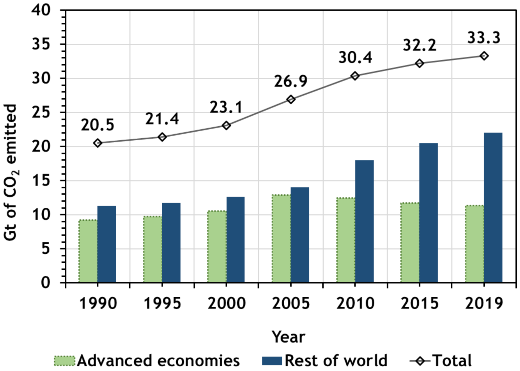
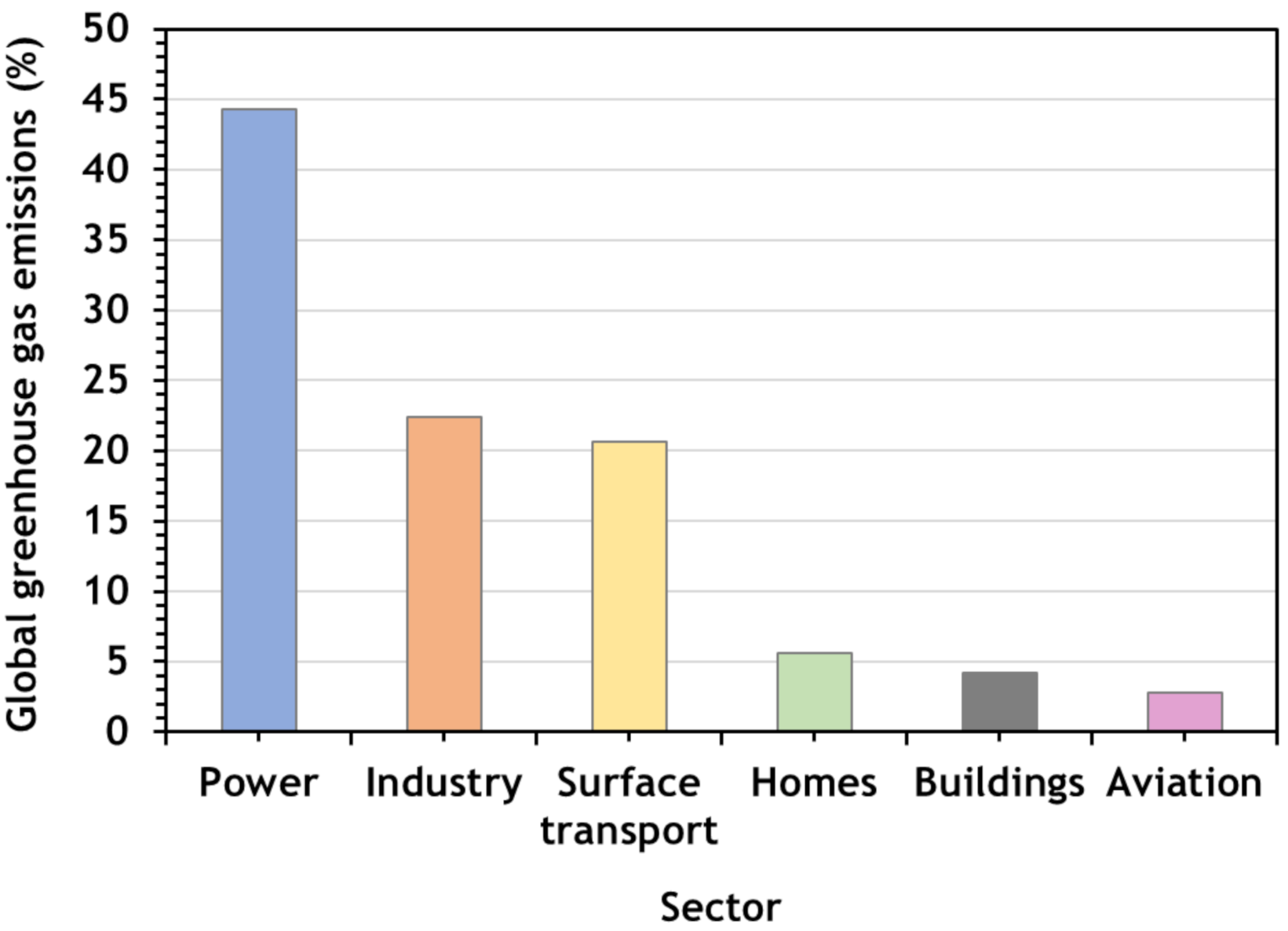
2. CO2 Emissions
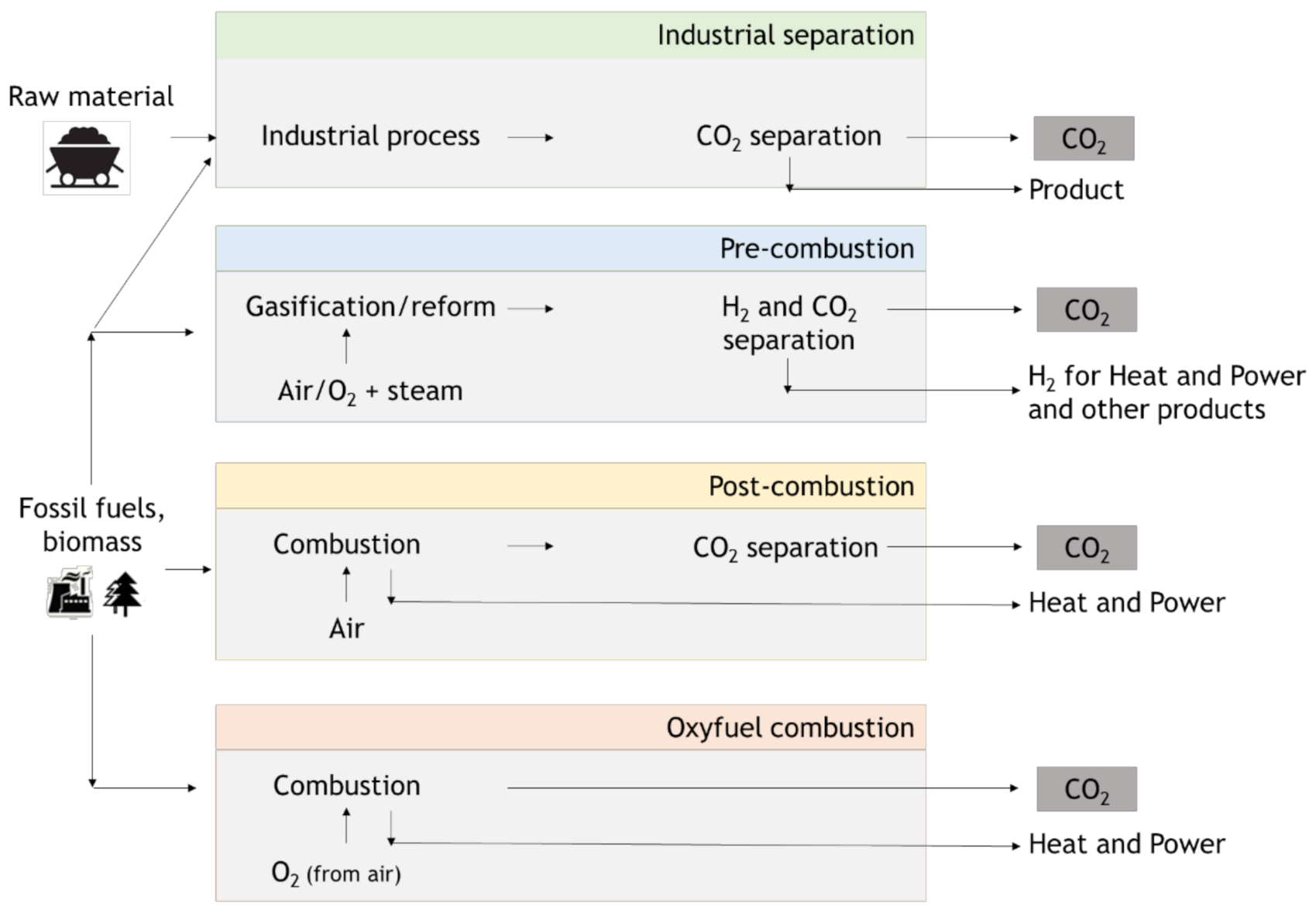
3. Carbon Capture (Utilization) and Storage (CCUS or CCS)
3.1. Pre-Combustion
3.2. Oxy-Combustion
3.3. Post-Combustion
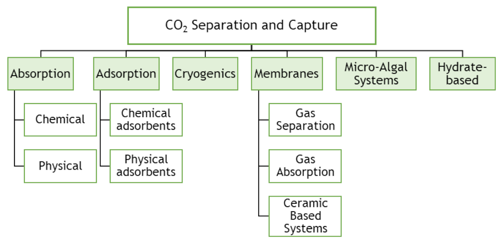
3.4. Technologies for CO2 Capture
3.5. Current Progress of CCUS Facilities
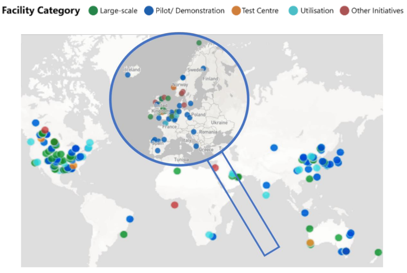
3.6. Global Facilities of CCUS
- (1)
- Commercial Carbon Capture and Storage Facilities–CO2 can be captured and transported to be permanently stored; have economic lives similar to the host facility whose CO2 is captured; must support a commercial return while operating and meet regulatory requirements;
- (2)
- Carbon Capture and Storage Hubs–Commercial facilities although not having a full-chain (capture, transport and storage) operation; several models are considered, combining multiple capture facilities, or CO2 transport and storage;
- (3)
- Pilot and Demonstration Facilities–CO2 is captured for testing, developing or demonstrating CCS technologies/processes; CO2 captured may or may not be transported for permanent storage; A commercial return during operation is not expected.
- Political: lack of political commitment with CCS by some member states;
- Economic: high investment, high operational costs, lack of competitiveness compared with other low carbon technologies; no financial compensation for the additional capital and operating costs associated with CCS; Long-term funding commitments from various public and private sources ensure the continuity of research programs which are necessary for the development of CO2 utilization;
- Technical: lack of infrastructures for transport and storage;
- Social: CCS is unknown for the overall public; resistance to CO2 storage concept; environmental risks concerning health and water pollution.
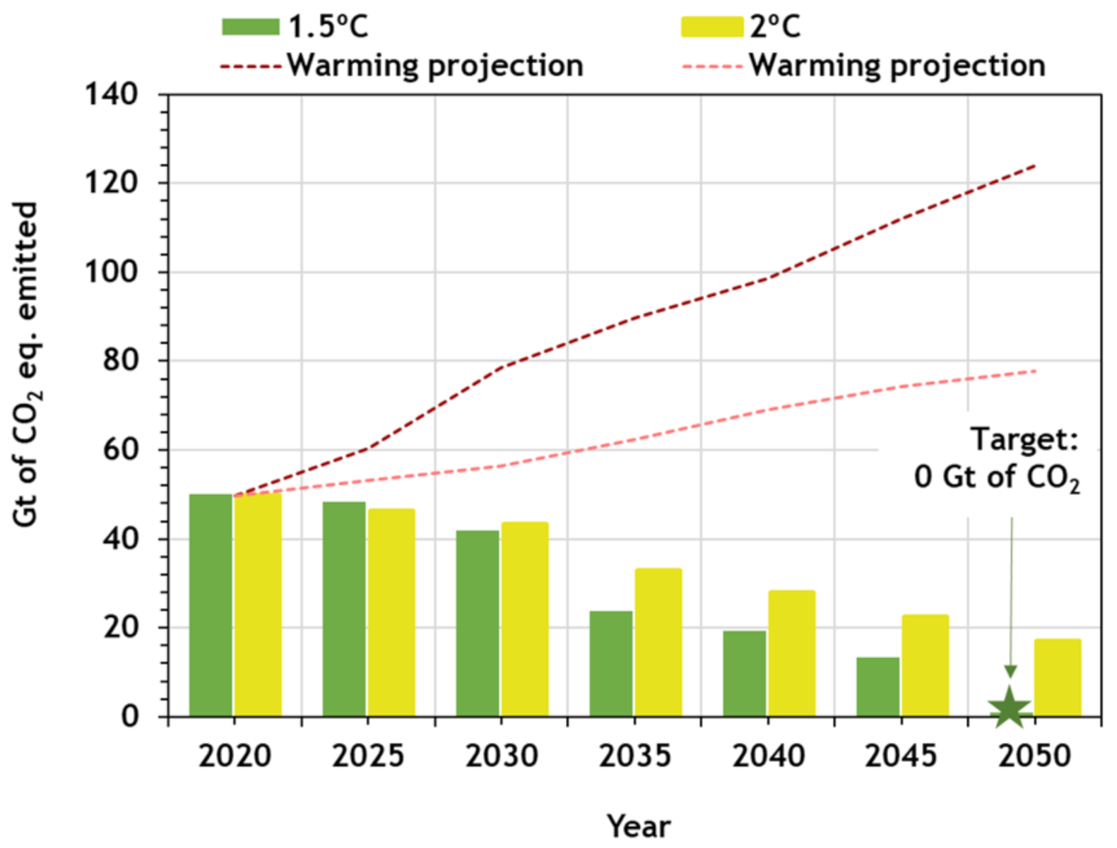
4. Climate Positive Solutions
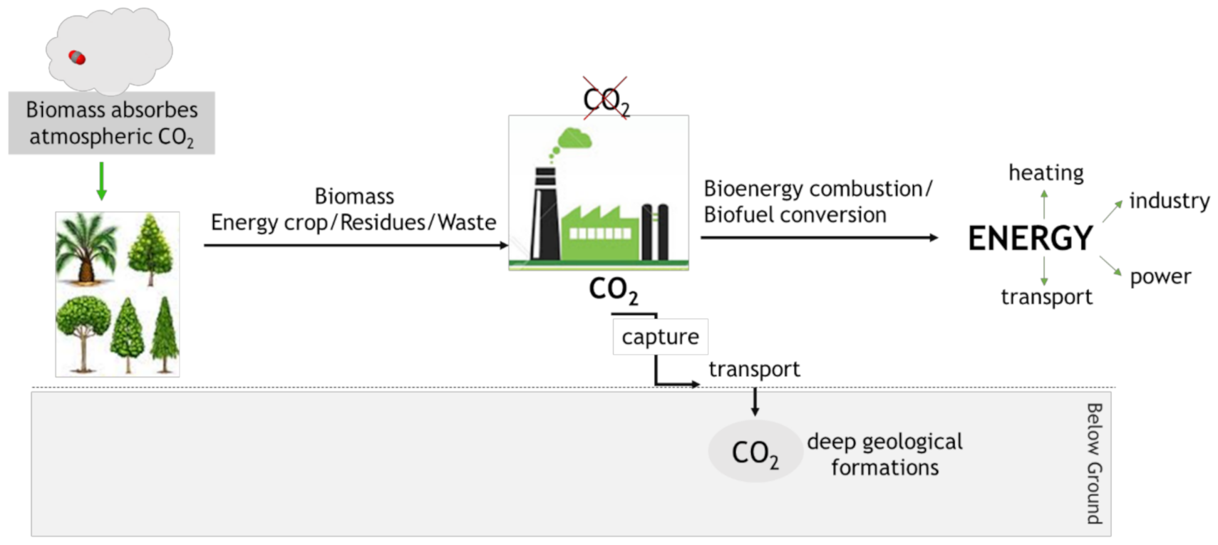
4.1. Bioenergy with Carbon Capture and Storage (BECCS)
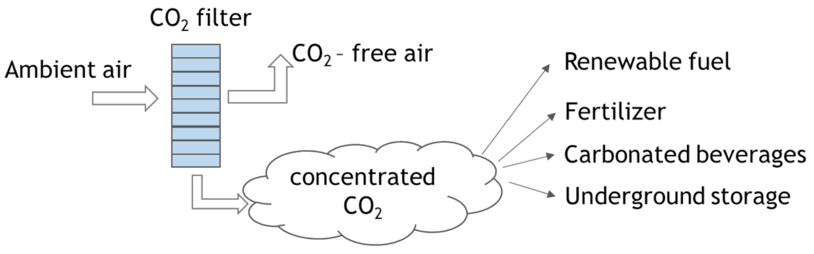
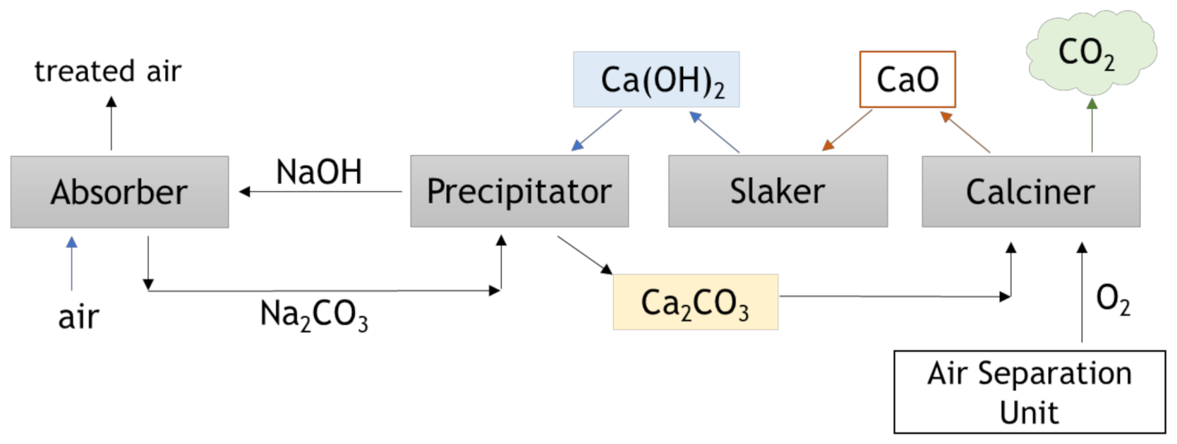
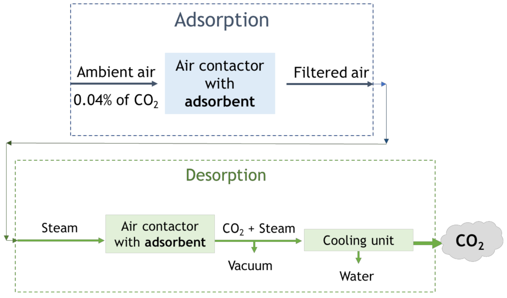
4.2. Direct Air Capture (DAC)
5. Industrial Processes
- Energy-related emissions: combustion of coal, oil, and natural gas (considering biomass with an emission factor of zero);
- Process emissions: associated with chemical and physical reactions, such as the production of aluminum, ferroalloys, lubricants and paraffins, and fuels through coal and gas-to-liquid processes, etc.;
- Direct emissions: all emissions associated with industrial processes, except the electricity, heat, and steam purchases (energy-related emissions plus process emissions);
- Indirect emissions: all emissions “out of the facilities”, including electricity, heat and steam purchased.
6. Conclusions
Author Contributions
Funding
Institutional Review Board Statement
Informed Consent Statement
Conflicts of Interest
Nomenclature
| AMP | 2-Amino-2-methyl-1-propanol |
| BECCS | Bioenergy with Carbon Capture and Storage |
| CCS | Carbon Capture and Storage |
| CCU | Carbon Capture and Utilization |
| CCUS | Carbon Capture, Utilization, and Storage |
| DAC | Direct Air Capture |
| DEA | Diethanolamine |
| EGR | Enhanced Gas Recovery |
| EOR | Enhanced Oil Recovery |
| ESA | Electrical Swing Adsorption |
| HBCC | Hydrate-based Carbon Dioxide Capture |
| IGCC | Integrated Gasification Combined Cycle |
| MDEA | Methyl diethanolamine |
| MEA | Monoethanolamine |
| PSA | Pressure Swing Adsorption |
| TSA | Temperature Swing Adsorption |
| TVSA | Temperature-Vacuum Swing Adsorption |
Appendix

| Name | Status | Country | Data | Industry | Observations |
|---|---|---|---|---|---|
| CATO Programme | O | The Netherlands | 2004 | Various | Responsible for covering the full CCS chain and addressing both fundamental and applied topics including regulation and safety and public perception |
| CO2 FieldLab Project | C | Norway | - | N/A | Project is led by Sintef Petroleum Research, with the purpose of testing the sensitivity of a variety of monitoring systems by observing the migration of small amounts of injected CO2 in the shallow subsurface |
| CO2 MultiStore Joint Industrial Project (JIP) | C | UK | 2012 | N/A | Project is led by Scottish Carbon Capture and Storage with joint funding and expert support from CCS project developers and public corporations, to support the development of multi-use regional CO2 storage assets |
| Hisarma Pilot Plant (Reducing CO2 Emissions in Steelmaking) | O | The Netherlands | 2007 | Iron and Steel Production | A coal-based Hisarna smelting reduction process in steelmaking industry was developed by Tata Steel, Rio Tinto and ULCOS partners, and it has been operational since 2011. CO2 emissions were reduced by 20%, and can be 80% lower when CCS is applied |
| QICS Project | C | UK | 2010 | N/A | Project led by the Plymouth Marine Laboratory, to quantify and monitor Environmental Impacts of Geological Carbon Storage involved in the assessment and monitoring of the first controlled release of CO2 into seaed sediments |
| Name | Status | Country | Data | Industry | Observations |
|---|---|---|---|---|---|
| ELCOGAS Pre-combustion Carbon Capture Pilot Project: Puertollano | C | Spain | 2010 | Power Generation | A pilot plant was integrated into the Puertollano IGCC plant in Spain to test the feasibility of pre-combustion technology to capture CO2 in an IGCC environment that uses solid fossil fuels and wastes as feedstock; operational tests occurred in 2010/2011 |
| Aberthaw Pilot Carbon Capture Facility | C | UK | 2013 | Power generation | A pilot-scale plant at the Aberthaw power station in South Wales UK tested the Cansolv integrated CO2 and SO2 removal system during 2013/2014 |
| Abu Dhabi CCS (Phase 1 being Enirates Steel Industries) | O | United Arab Emirates | 2016 | Iron and Steel Production | First fully commercial CCS facility in the iron and steel industry, and involves the CO2 capture via a new build CO2 Compression facility using high purity CO2 produced as a by-product of the direct reduced iron-making process at the Emirates Steel Industries factory in Mussafah. The compression facility has a capture capacity of 0.8 Mtpa. The CO2 is captured and is transported via pipeline to Abu Dhabi National Oil Company ADNOC oil reservoirs for EOR |
| Acorn (Minimum Viable CCS Development) | AD | United Kingdom | 2021–2022 | Various | Initiate a low cost full chain CCS project in the North East of Scotland; cluster of capture, transport and storage infrastructure; CO2 is separated from natural gas and vented, adjacent to an offshore transport pipeline, which connects to a well understood offshore basin, rich in storage opportunities |
| Brindisi CO2 Capture Pilot Plant | C | Italy | 2010 | Power Generation | A pilot-scale plant at the Brindisi power plant in south-eastern Italy tested a number of solvent technologies during 2010–2012 |
| Buggenum Carbon Capture (CO2 Catch-up) Pilot Project | C | The Netherlands | 2011 | Power Generation | A pilot-scale plant at the Willem-Alexander power plant in The Netherlands (now closed) undertook a CO2 capture testing and R&D program between 2011 and 2013 |
| C2A2 Field Pilot-Le Havre | C | France | 2013 | Power Generation | A pilot-scale plant at the Le Havre power plant in France tested a specific carbon capture technology during parts of 2013 and 2014 |
| CarbFix Project | O | Iceland | 2012 | Power Generation | Study of injection of pure CO2 and a gas mixture of CO2 and H2S, dissolved in water, into basaltic formations; pilot tests in 2012 injected over 200 tonnes of CO2 from a geothermal power plant |
| CASTOR | C | Denmark | 2006 | Power Generation | Tests of three solvents in a post-combustion pilot plant located at the coal-fired Esbjerg power plant in Denmark |
| CEMCAP | C | Norway | 2015 | Cement Production | Prepare the ground for large-scale implementation of CO2 capture in the European cement industry; designed to strengthen and complement the Norcem and ECRA CCS projects; technical development, including technology demonstration in a simulated industrial environment. |
| CESAR | C | Denmark | 2008 | Power Generation | Project for the post-combustion capture work undertaken at the coal-fired Esbjerg pilot plant in Denmark under the CASTOR project; modifications to the Esbjerg pilot plant were undertaken during 2008, after which a three test campaign was conducted covering a benchmark and two novel solvents |
| CIUDEN: CO2 Capture & Transport Technology Development Plant | C | Spain | 2012 | Power Generation | The Hontomin Technology Development Plant—CO2 Capture & Transport the CIUDEN Technology Development Center, successfully completed the full CO2 capture process, using oxy-combustion in the circulating fluidized bed CFB boiler with the compression and purification unit |
| CIUDEN: CO2 Storage Technology Development Plant | O | Spain | 2015 | N/A | The Hontomin Storage Technology Development Plant—the site includes one injection well and a monitoring well;10,000 tonnes of CO2 are planned to be injected in the period 2017–2020 |
| CO2 Capture Test Facility at Norcem Brevik | C | Norway | 2013 | Cement Production | A real cement flue gas at the Brevik plant in Norway was used to test three different post-combustion technologies, while investigations on a fourth technology were performed offsite based on a pilot installed at Stuttgart University; tests were done from 2013 to 2017 and aimed to demonstrate the CO2 capture from a cement plant, to improve understanding of these technologies for large-scale application |
| DMX™ Demonstration in Dunkirk | AD | France | 2022 | Iron and Steel Production | Designed by Axens, started in 2020 at the ArcelorMittal steelworks site in Dunkirk; able to capture 0.5 metric tonnes of CO2 an hour from steelmaking gases by 2022 |
| Drax bioenergy carbon capture pilot plant | O | United Kingdom | 2019 | Power Generation | The CO2 capture pilot plant captures 1 tpd from the Drax power station unit, which runs 100% biomass feedstock |
| ELCOGAS Pre-combustion Carbon Capture Pilot Project: Puertollano | C | Spain | 2010 | Power Generation | A pilot plant was integrated into the Puertollano IGCC plant in Spain to test the feasibility of pre-combustion technology to capture CO2 in an IGCC environment that uses solid fossil fuels and wastes as the main feedstock |
| Ferrybridge Carbon Capture Pilot (CCPilot100+) | C | United Kingdom | 2011 | Power Generation | Involves the capture of 100 tpd of CO2 from a flue gas stream at the Ferrybridge power station; designed to test the application of an amine-based, post-combustion capture process under realistic operating conditions |
| Geothermal Plant with CO2 Re-injection | C | Croatia | 2018 | Power Generation | A hybrid geothermal system is used, utilizing the energy potential of hot brines with dissolved natural gases to deliver combined heat and power at its Draškovec development; is expected to supply 17–18 MW of power; CO2 separation, capture and injection capacity is at around 50,000 tpa |
| K12-B CO2 Injection Project | C | The Netherlands | 2004 | Natural Gas Processing | CO2 is captured at the offshore natural gas production facility at the K12-B gas field and injected back into the depleted gas reservoir; cumulative injection in 2017 was over 100,000 tonnes |
| Karlshamn Field Pilot | C | Sweden | 2009 | Power Generation | One of a number of test facilities used by Alstom to test the viability of its Chilled Ammonia Process for CO2 capture and involved the capture of around 30 tpd of CO2 |
| Ketzin Pilot Project | C | Germany | 2004 | Power Generation and Hydrogen Production | The first geological CO2 storage project on the European mainland and one of the largest storage pilot projects in the world; constituted by three phases, over 67,000 tonnes of CO2 were injected between 2008 and 2013, and post-injection and site behavior monitoring completed in 2017 |
| La Pereda Calcium Looping Pilot Plant | C | Spain | 2012 | Power Generation | In operation in 2012, undertook three European funded ‘projects’ or test campaigns, testing the viability of post-combustion capture by calcium looping, 1.7 MWth |
| Lacq CCS Pilot Project | C | France | 2010 | Power Generation | A storage-focused project of global significance that injected 51,000 tonnes of CO2 over a 39 month period from 2010 to 2013; including a comprehensive monitoring plan |
| LEILAC—Low Emissions Intensity Lime and Cement Project | In C | Belgium | 2020’s | Cement Production | Designed, built and operated a pilot plant to: Direct Separation calcining technology can work at the temperatures necessary to process limestone for the lime and cement industries; capture over 95% of the CO2 emissions from both industries without significant energy or capital penalty |
| Renfrew Oxy-fuel (Oxycoal 2) Project | C | United Kingdom | 2007 | Power Generation | Consisted of an initial oxy-fuel technology mapping phase followed by testing of a 40-MWth oxy-fuel burner at Renfrew, Scotland, under realistic operating conditions and included testing adaptation from air-firing to oxy-fuel firing on pulverized coal; the pilot facility completed 20 test days |
| Schwarze Pumpe Oxy-fuel Pilot Plant | C | Germany | 2008 | Power Generation | The 30 MWth Schwarze Pumpe oxy-fuel pilot was the world’s first large-scale testing of the entire oxy-fuel combustion technology chain; In 2014, it was discontinued research into coal-fired power with CCS; the pilot plant captured and liquefied 11,000 tonnes of CO2; Around 1500 tonnes of CO2 from the Schwarze Pumpe oxy-fuel capture pilot plant were injected |
| STEPWISE Pilot of SEWGS Technology at Swerea/Mefos | O | Sweden | 2017 | Iron and Steel Production | The Sorption Enhanced Water Gas Shift reaction SEWGS process is to be demonstrated at a CO2 capture rate of 14 tonnes per day; the pilot plant is fed with blast furnace gas from the adjacent steel plant of SSAB; the test facility was launched in September 2017 |
| Wilhelmshaven CO2 Capture Pilot Plant | C | Germany | 2012 | Power Generation | CO2 capture from a side stream of the Wilhelmshaven coal-fired power station; designed to capture 70 tpd of CO2 at full capacity; achieved 4500 h of operation in the first quarter of 2014 |
| Name | Status | Country | Data | Industry | Observations |
|---|---|---|---|---|---|
| Technology Centre Mongstad (TCM) | O | Norway | 2012 | Oil Refining | The demonstration test facility comprises two capture units, one designed for amine-based solvents and the other for chilled aqueous ammonia |
| UKCCSRC Pilot-scale Advanced Capture Technology (PACT) | O | United Kingdom | - | Power Generation | PACT facilities bring together a range of integrated pilot-scale and accompanying specialist research and analytical facilities, supported by leading academic expertise; post-combustion pilot is installed and is jointly operated by the Universities of Leeds and Sheffield |
| Name | Status | Country | Data | Industry | Observations |
|---|---|---|---|---|---|
| ArcelorMittal Steelanol Ghent | In C | Belgium | 2020 | Iron and Steel Production | ArcelorMittal Steelanol Ghent |
| Port Jérôme CO2 Capture Plant | O | France | 2015 | Hydrogen Production | Port Jérôme CO2 Capture Plant |
| Twence Waste-to-energy CO2 Capture and Utilisation | O | The Netherlands | 2014 | Waste Incineration | Twence Waste-to-energy CO2 Capture and Utilisation |
References
- Climate Change Service. Surface Air Temperature for September 2019. Available online: https://climate.copernicus.eu/surface-air-temperature-september-2019 (accessed on 14 March 2021).
- Borowski, P.F. Nexus between water, energy, food and climate change as challenges facing the modern global, European and Polish economy. AIMS Geosci. 2020, 6, 397–421. [Google Scholar] [CrossRef]
- Folger, P. Carbon Capture: A Technology Assesssment; Congressional Research Service: Washington, DC, USA, 2013; p. 3. [Google Scholar]
- Lallanilla, M. Greenhouse Gas Emissions: Causes & Sources. Available online: http://www.livescience.com/37821-greenhouse-gases.html (accessed on 26 May 2016).
- Jefferson, M. Energy policies for sustainable development. In World Energy Assessment: Energy and the Challenge of Sustainability; Communications Development Incorporated: Washington, DC, USA, 2000. [Google Scholar]
- Green, C.; Byrne, K. Biomass: Impact on Carbon Cycle and Greenhouse Gas Emissions. Encycl. Energy 2004, 1, 223–236. [Google Scholar] [CrossRef]
- Quadrelli, R.; Peterson, S. The energy-climate challenge: Recent trends in CO2 emissions from fuel combustion. Energy Policy 2007, 35, 5938–5952. [Google Scholar] [CrossRef]
- Olajire, A.A. CO2 capture and separation technologies for end-of-pipe applications—A review. Energy 2010, 35, 2610–2628. [Google Scholar] [CrossRef]
- Masson-Delmotte, V. Global Warming of 1.5 °C.; IPCC—Intergovernmental Panel on Climate Change: Geneva, Switzerland, 2019; ISBN 978-92-9169-153-1. [Google Scholar]
- Masson-Delmotte, V.P.; Zhai, H.-O.; Pörtner, D.; Roberts, J.; Skea, P.R.; Shukla, A.; Pirani, W.; Moufouma-Okia, C.; Péan, R.; Pidcock, S.; et al. Global Warming of 1.5 °C. An IPCC Special Report on the Impacts of Global Warming of 1.5 °C above Pre-Industrial Levels and Related Global Greenhouse Gas Emission Pathways, in the Context of Strengthening the Global Response to the Threat of Climate Change, Sustainable Development, and Efforts to Eradicate Poverty; IPCC: Geneva, Switzerland, 2018. [Google Scholar]
- Foley, A.; Smyth, B.M.; Pukšec, T.; Markovska, N.; Duić, N. A review of developments in technologies and research that have had a direct measurable impact on sustainability considering the Paris agreement on climate change. Renew. Sustain. Energy Rev. 2017, 68, 835–839. [Google Scholar] [CrossRef]
- Sekera, J.; Lichtenberger, A. Assessing Carbon Capture: Public Policy, Science, and Societal Need. Biophys. Econ. Sustain. 2020, 5, 14. [Google Scholar] [CrossRef]
- Bui, M.; Adjiman, C.S.; Bardow, A.; Anthony, E.J.; Boston, A.; Brown, S.; Fennell, P.S.; Fuss, S.; Galindo, A.; Hackett, L.A.; et al. Carbon capture and storage (CCS): The way forward. Energy Environ. Sci. 2018, 11, 1062–1176. [Google Scholar] [CrossRef]
- Consoli, C. Bioenergy and Carbon Capture and Storage; Global CCS Institute: Docklands, Australia, 2019. [Google Scholar]
- International Energy Agency. Global Emissions in 2019. Available online: https://www.iea.org/articles/global-co2-emissions-in-2019 (accessed on 18 March 2021).
- International Energy Agency. Global Energy Review 2020; International Energy Agency: Paris, France, 2020; Available online: https://www.iea.org/reports/global-energy-review-2020 (accessed on 18 March 2021).
- Tiseo, I. Global Distribution of CO2 Emissions from Fossil Fuel and Cement by Sector 2020. Available online: https://www.statista.com/statistics/1129656/global-share-of-co2-emissions-from-fossil-fuel-and-cement/ (accessed on 18 March 2021).
- Climate Action Tracker. 2100 Warming Projections. Available online: https://climateactiontracker.org/global/temperatures/ (accessed on 18 April 2021).
- CarbonBrief—Clear on Climate. Explainer: The high-emissions ‘RCP8.5′ global warming scenario. Available online: https://www.carbonbrief.org/explainer-the-high-emissions-rcp8-5-global-warming-scenario (accessed on 3 September 2020).
- Pires, J.C.M.; Martins, F.G.; Alvim-Ferraz, M.C.M.; Simões, M. Recent developments on carbon capture and storage: An overview. Chem. Eng. Res. Des. 2011, 89, 1446–1460. [Google Scholar] [CrossRef]
- Songolzadeh, M.; Ravanchi, M.T.; Soleimani, M. Carbon Dioxide Capture and Storage: A General Review on Adsorbents. World Acad. Sci. Eng. Technol. 2012, 6, 213–220. [Google Scholar]
- International Energy Agency. Carbon Capture, Utilisation and Storage. Available online: https://www.iea.org/fuels-and-technologies/carbon-capture-utilisation-and-storage (accessed on 3 August 2020).
- Marocco Stuardi, F.; MacPherson, F.; Leclaire, J. Integrated CO2 capture and utilization: A priority research direction. Curr. Opin. Green Sustain. Chem. 2019, 16, 71–76. [Google Scholar] [CrossRef]
- Romasheva, N.; Ilinova, A. CCS Projects: How Regulatory Framework Influences Their Deployment. Resources 2019, 8, 181. [Google Scholar] [CrossRef]
- Global CCS Institute. The Global Status of CCS; Summary report; Global Carbon Capture and Storage Institute Ltd.: Melbourne, Australia, 2015; Available online: https://www.globalccsinstitute.com/wp-content/uploads/2018/12/Global-Status-Report_2015_Summary.pdf (accessed on 3 August 2020).
- International Energy Agency. Energy Technology Perspectives; International Energy Agency: Paris, France, 2017; Available online: https://www.iea.org/topics/energy-technology-perspectives (accessed on 18 March 2021).
- International Energy Agency. Transforming Industry through CCUS. 2019. Available online: https://www.iea.org/reports/transforming-industry-through-ccus (accessed on 18 March 2021).
- Dindi, A.; Quang, D.V.; Vega, L.F.; Nashef, E.; Abu-Zahra, M.R.M. Applications of fly ash for CO2 capture, utilization, and storage. J. CO2 Util. 2019, 29, 82–102. [Google Scholar] [CrossRef]
- IPCC. IPCC Special Report on Carbon Dioxide Capture and Storage; Prepared by Working Group III of the Intergovernmental Panel on Climate Change; Metz, B.O., Davidson, H.C., de Coninck, M.L., Meyer, L.A., Eds.; Cambridge University Press: Cambridge, UK; New York, NY, USA, 2005; p. 442. [Google Scholar]
- Nota, G.; Nota, F.D.; Peluso, D.; Toro Lazo, A. Energy Efficiency in Industry 4.0: The Case of Batch Production Processes. Sustainability 2020, 12, 6631. [Google Scholar] [CrossRef]
- Global CCS Institute. CO2 Capture Technologies; Global Carbon Capture and Storage Institute: Canberra, Australia, 2012; pp. 1–13. [Google Scholar]
- Pastor-Pérez, L.; Baibars, F.; Le Sache, E.; Arellano-García, H.; Gu, S.; Reina, T.R. CO2 valorisation via Reverse Water-Gas Shift reaction using advanced Cs doped Fe-Cu/Al2O3 catalysts. J. CO2 Util. 2017, 21, 423–428. [Google Scholar] [CrossRef]
- Rackley, S.A. Carbon Capture from Power Generation, 2nd ed.; Carbon Capture and Storage; Elsevier: London, UK, 2017; ISBN 9780128120415. [Google Scholar]
- U.S. Department Energy. Pre-Combustion CO2 Capture. Available online: https://www.energy.gov/fe/science-innovation/carbon-capture-and-storage-research/carbon-capture-rd/pre-combustion-carbon (accessed on 15 August 2020).
- National Energy Technology Laboratory Post-Combustion CO2 Capture. Available online: https://www.netl.doe.gov/coal/carbon-capture/post-combustion (accessed on 1 April 2021).
- Buhre, B.J.P.; Elliott, L.K.; Sheng, C.D.; Gupta, R.P.; Wall, T.F. Oxy-fuel combustion technology for coal-fired power generation. Prog. Energy Combust. Sci. 2005, 31, 283–307. [Google Scholar] [CrossRef]
- Wong, S. Module 3—CO2 Capture: Pre-Combustion (Decarbonisation) and Oxy-Fuel Technologies; Global CCS Institute: Docklands, VIC, Australia, 2011; Volume 1, pp. 45–54. Available online: https://www.globalccsinstitute.com/archive/hub/publications/114711/building-capacity-co2-capture-and-storage-apec-region (accessed on 3 August 2020).
- Armstrong, K.; Styring, P. Assessing the Potential of Utilization and Storage Strategies for Post-Combustion CO2 Emissions Reduction. Front. Energy Res. 2015, 3. [Google Scholar] [CrossRef]
- Bhown, A.S.; Freeman, B.C. Analysis and Status of Post-Combustion Carbon Dioxide Capture Technologies. Environ. Sci. Technol. 2011, 45, 8624–8632. [Google Scholar] [CrossRef]
- Leung, D.Y.C.; Caramanna, G.; Maroto-Valer, M.M. An overview of current status of carbon dioxide capture and storage technologies. Renew. Sustain. Energy Rev. 2014, 39, 426–443. [Google Scholar] [CrossRef]
- Luis, P. Use of monoethanolamine (MEA) for CO2 capture in a global scenario: Consequences and alternatives. Desalination 2016, 380, 93–99. [Google Scholar] [CrossRef]
- Walspurger, S.; Van Dijk, H.A.J. EDGAR CO2 Purity: Type and Quantities of Impurities Related to CO2 Point Source and Capture Technology: A Literature Study; The Energy Research Centre of The Netherlands: Petten, The Netherlands, 2012. [Google Scholar]
- Samanta, A.; Zhao, A.; Shimizu, G.K.H.; Sarkar, P.; Gupta, R. Post-Combustion CO2 Capture Using Solid Sorbents: A Review. Ind. Eng. Chem. Res. 2012, 51, 1438–1463. [Google Scholar] [CrossRef]
- Grande, C.A. Advances in Pressure Swing Adsorption for Gas Separation. ISRN Chem. Eng. 2012, 2012, 13. [Google Scholar] [CrossRef]
- Regufe, M.J.; Ribeiro, A.M.; Ferreira, A.F.P.; Rodrigues, A. CO2 Storage on Zeolites and Other Adsorbents. In Nanoporous Materials for Gas Storage; Kaneko, K., Rodríguez-Reinoso, F., Eds.; Springer: Singapore, 2019; pp. 359–381. [Google Scholar]
- Yang, H.; Li, J.-R. Metal-Organic Frameworks (MOFs) for CO2 Capture. In Porous Materials for Carbon Dioxide Capture; Lu, A.-H., Dai, S., Eds.; Springer: Berlin/Heidelberg, Germany, 2014; pp. 79–113. [Google Scholar]
- Regufe, M.J.; Tamajon, J.; Ribeiro, A.M.; Ferreira, A.; Lee, U.H.; Hwang, Y.K.; Chang, J.-S.; Serre, C.; Loureiro, J.M.; Rodrigues, A.E. Syngas Purification by Porous Amino-Functionalized Titanium Terephthalate MIL-125. Energy Fuels 2015, 29, 4654–4664. [Google Scholar] [CrossRef]
- Lu, C.; Bai, H.; Wu, B.; Su, F.; Hwang, J.F. Comparative study of CO2 capture by carbon nanotubes, activated carbons, and zeolites. Energy Fuels 2008, 22, 3050–3056. [Google Scholar] [CrossRef]
- Regufe, M.J.; Ferreira, A.F.P.; Loureiro, J.M.; Rodrigues, A.; Ribeiro, A.M. Development of Hybrid Materials with Activated Carbon and Zeolite 13X for CO2 Capture from Flue Gases by Electric Swing Adsorption. Ind. Eng. Chem. Res. 2020, 59, 12197–12211. [Google Scholar] [CrossRef]
- Regufe, M.J.; Ferreira, A.F.P.; Loureiro, J.M.; Rodrigues, A.; Ribeiro, A.M. Electrical conductive 3D-printed monolith adsorbent for CO2 capture. Microporous Mesoporous Mater. 2019, 278, 403–413. [Google Scholar] [CrossRef]
- Clodic, D.; Younes, M. A new Method for CO2 Capture: Frosting CO2 at Atmospheric Pressure. In Proceedings of the Greenhouse Gas Control Technologies—6th International Conference, Kyoto, Japan, 1–4 October 2002; Gale, J., Kaya, Y., Eds.; Pergamon: Oxford, UK, 2003; pp. 155–160. [Google Scholar]
- Tuinier, M.J.; van Sint Annaland, M.; Kramer, G.J.; Kuipers, J.A.M. Cryogenic CO2 capture using dynamically operated packed beds. Chem. Eng. Sci. 2010, 65, 114–119. [Google Scholar] [CrossRef]
- Nanda, S.; Reddy, S.N.; Mitra, S.K.; Kozinski, J.A. The progressive routes for carbon capture and sequestration. Energy Sci. Eng. 2016, 4, 99–122. [Google Scholar] [CrossRef]
- Hart, A.; Gnanendran, N. Cryogenic CO2 capture in natural gas. Energy Procedia 2009, 1, 697–706. [Google Scholar] [CrossRef]
- Kenarsari, S.D.; Yang, D.; Jiang, G.; Zhang, S.; Wang, J.; Russell, A.G.; Wei, Q.; Fan, M. Review of recent advances in carbon dioxide separation and capture. RSC Adv. 2013, 3, 22739–22773. [Google Scholar] [CrossRef]
- Klinthong, W.; Yang, Y.-H.; Huang, C.-H.; Tan, C.-S. A Review: Microalgae and Their Applications in CO2 Capture and Renewable Energy. Aerosol Air Qual. Res. 2015, 15, 712–742. [Google Scholar]
- Yang, M.; Song, Y.; Jiang, L.; Zhao, Y.; Ruan, X.; Zhang, Y.; Wang, S. Hydrate-based technology for CO2 capture from fossil fuel power plants. Appl. Energy 2014, 116, 26–40. [Google Scholar] [CrossRef]
- Zheng, J.; Chong, Z.R.; Qureshi, M.F.; Linga, P. Carbon Dioxide Sequestration via Gas Hydrates: A Potential Pathway toward Decarbonization. Energy Fuels 2020. [Google Scholar] [CrossRef]
- Matsuo, S.; Umeda, H.; Takeya, S.; Fujita, T.A. Feasibility Study on Hydrate-Based Technology for Transporting CO2 from Industrial to Agricultural Areas. Energies 2017, 10, 728. [Google Scholar] [CrossRef]
- International Energy Agency, CCUS in Clean Energy Transitions. Available online: https://www.iea.org/reports/ccus-in-clean-energy-transitions/a-new-era-for-ccus (accessed on 18 March 2021).
- Svante. Capturing Carbon Economically, Today. Available online: https://svanteinc.com/carbon-capture-technology/ (accessed on 18 March 2021).
- Air Products. Carbon Capture. Available online: https://www.airproducts.com/company/innovation/carbon-capture#/ (accessed on 18 March 2021).
- Global CCS Institute. Facilities Database. Available online: https://co2re.co/FacilityData (accessed on 4 August 2020).
- Townsend, A.; Gillespie, A. Scalling Up the CCS Market to Deliver Net-Zero Emissions; Global CCS Institute: Docklands, Australia, 2020; Available online: https://www.globalccsinstitute.com/wp-content/uploads/2020/04/Thought-Leadership-Scaling-up-the-CCS-Market-to-Deliver-Net-Zero-Emissions-Digital-6.pdf (accessed on 18 March 2021).
- Budinis, S.; Krevor, S.; Dowell, N.M.; Brandon, N.; Hawkes, A. An assessment of CCS costs, barriers and potential. Energy Strategy Rev. 2018, 22, 61–81. [Google Scholar] [CrossRef]
- Karayannis, V.; Charalampides, G.; Lakioti, E. Socio-economic Aspects of CCS Technologies. Procedia Econ. Financ. 2014, 14, 295–302. [Google Scholar] [CrossRef]
- Stigson, P.; Hansson, A.; Lind, M. Obstacles for CCS deployment: An analysis of discrepancies of perceptions. Mitig. Adapt. Strateg. Glob. Chang. 2012, 17, 601–619. [Google Scholar] [CrossRef]
- Ranjan, M.; Herzog, H.J. Feasibility of air capture. Energy Procedia 2011, 4, 2869–2876. [Google Scholar] [CrossRef]
- Gutknecht, V. Awesome Extractors. Available online: https://mag.ebmpapst.com/en/industries/refrigeration-ventilation/awesome-extractors_12472/ (accessed on 6 August 2020).
- Sandalow, D.; Friedmann, J.; McCormick, C.; McCoy, S. Direct Air Capture of Carbon Dioxide. 2018. Available online: https://www.globalccsinstitute.com/wp-content/uploads/2020/06/JF_ICEF_DAC_Roadmap-20181207-1.pdf (accessed on 18 March 2021).
- Mazzotti, M.; Baciocchi, R.; Desmond, M.J.; Socolow, R.H. Direct air capture of CO2 with chemicals: Optimization of a two-loop hydroxide carbonate system using a countercurrent air-liquid contactor. Clim. Chang. 2013, 118, 119–135. [Google Scholar] [CrossRef]
- Ocean Studies Board and National Academies of Sciences Engineering, and Medicine. Negative Emissions Technologies and Reliable Sequestration: A Research Agenda; The National Academies Press: Washington, DC, USA, 2019. [Google Scholar]
- Sinha, A.; Realff, M.J. A parametric study of the techno-economics of direct CO2 air capture systems using solid adsorbents. AIChE J. 2019, 65, e16607. [Google Scholar] [CrossRef]
- Keith, D.W.; Holmes, G.; St. Angelo, D.; Heidel, K. A Process for Capturing CO2 from the Atmosphere. Joule 2018, 2, 1573–1594. [Google Scholar] [CrossRef]
- Carbon Engineering Ltd. Direct Air Capture. Available online: https://carbonengineering.com/our-technology/ (accessed on 18 March 2021).
- Beuttler, C.; Charles, L.; Wurzbacher, J. The Role of Direct Air Capture in Mitigation of Anthropogenic Greenhouse Gas Emissions. Front. Clim. 2019, 1, 10. [Google Scholar] [CrossRef]
- International Energy Agency. Direct Air Capture; International Energy Agency: Paris, France, 2020; Available online: https://www.iea.org/reports/direct-air-capture (accessed on 9 April 2021).
- Creutzig, F.; Breyer, C.; Hilaire, J.; Minx, J.; Peters, G.; Socolow, R. The mutual dependence of negative emission technologies and energy systems. Energy Environ. Sci. 2019, 12, 1805–1817. [Google Scholar] [CrossRef]
- Fasihi, M.; Efimova, O.; Breyer, C. Techno-economic assessment of CO2 direct air capture plants. J. Clean. Prod. 2019, 224, 957–980. [Google Scholar] [CrossRef]
- Sandalow, D.; Friedmann, J.; Aines, R.; McCormick, C.; McCoy, S.; Stolaroff, J. Industrial Heat Decarbonization Roadmap; ICEF–Innovation for Coal Earth Forum: Tokyo, Japan, 2019. [Google Scholar]


| Technology Readiness Level | Current Development |
|---|---|
| TRL1 | Concept |
| TRL2 | Formulation |
 | Ocean Storage |
| TRL3 | Proof of concept (lab tests) |
 | Ionic Liquids-Post-combustion |
 | BECCS Power |
 | Low T separation-Pre-combustion |
 | Membranes dense inorganic (CO2 separation) |
 | Mineral storage |
| TRL4 | Lab prototype |
 | Oxy-combustion gas turbine (water cycle) |
| TRL5 | Lab-scale plant |
 | Membranes dense inorganic (H2 separation for reformer) |
| TRL6 | Pilot plant |
 | Membranes polymeric (power plants) |
 | Biphasic solvents-Post-combustion |
 | Chemical looping combustion (CLC) |
 | Calcium carbonate looping (CaL) |
 | CO2 utilization (non-EOR) |
| TRL7 | Demonstration |
 | Membranes polymeric (NG industry) |
 | Pre-combustion IGCC + CCS |
 | Oxy-combustion coal power plant |
 | Adsorption-Post-combustion |
 | BECCS industry |
 | DAC |
 | Depleted oil & gas fields |
 | CO2-EGR |
| TRL8 | Commercial Refinement required |
| TRL9 | Commercial |
 | Post-combustion amines (power plants) |
 | Pre-combustion NG processing |
 | Transport on-shore & off-shore pipelines |
 | Transport ships |
 | Saline formations |
 | CCUS |
| Name | Status | Country | Data | Industry | Observations |
|---|---|---|---|---|---|
| Acorn Scalable CCS Development | ED | UK | 2020s | Oil Refining | Scale-up of the pilot project Acorn (Minimum Viable CCS Development) |
| Caledonia Clean Energy | ED | UK | 2024 | Power generation | CO2 capture would be 3 Mtpa and transported via re-purposed pipeline for geological storage in the North Sea of Scotland |
| Drax BECCS Project | ED | UK | 2027 | Power generation | Aims to capture 4 Mtpa from one (660 MW) of the biomass-fired power lines at the UK’s biggest power station by 2027 |
| Ervia Cork CCS | ED | Ireland | 2028 | Power generation and refining | CO2 captured initially from the two-modern gas-fired, combined-cycle gas turbine power stations and Ireland’s only oil refining business; transported via a pipeline network to sites in the Kinsale Gas Field |
| Hydrogen to Humber Saltend (H2H) | ED | UK | 2026–2027 | Hydrogen production | H2H Saltend is in development to produce blue hydrogen via a new build 600 MW autothermal reformer to decarbonize Triton Power’s gas-fired power plant; up to 1.4 million tonnes of CO2 will be captured. |
| Hydrogen 2 Magnum (H2M) | ED | Netherlands | 2004 | Power generation | H2M produce hydrogen to be used in gas power plant in Eemshaven, Germany, Equinor, Vattenfall and Gassunie |
| HyNet North West | ED | UK | Mid 2020s | Hydrogen Production | CO2 is planned to be captured from the Hydrogen Production & Carbon Capture plant, and transported, together with captured CO2 from existing nearby industrial sites |
| Langskip CCS–Fortum Oslo Varme | AD | Norway | 2024 | Waste Incineratiom | It is in construction to capture about 0.4 Mtpa of CO2 by 2024 from its cement production plat in southern Norway; the offshore Aurora area has been evaluated as original storage site and will involve a combined ship and pipeline transportation system. |
| Net Zero Teesside | ED | UK | 2020s | Various | Cluster of leading energy-intensive companies to examine the opportunity to build one of Europe’s first CCS equipped industrial zones in Tees Valley, UK; starts with a capture capacity of 0.8 Mtpa, that could grow up to 10 Mtpa; CO2 transported via pipeline to an offshore site in the North Sea |
| Northern Gas Network H21 North of England | AD | UK | 2026 | Hydrogen production | H21 aims to convert the UK gas grid from natural gas (methane) to zero-carbon hydrogen |
| Norway Full Chain CCS | AD | Norway | 2023–2024 | Various | Aim of 0.8 Mtpa; Capture CO2 studies are being undertaken by two proponents involved in cement production and a waste-to-energy recovery plant, both in southern Norway; CO2 would be transported via ship and pipeline to an offshore in the Smeaheia area |
| Port of Rotterdam CCUS Backbone Initiative (Porthos) | AD | Netherlands | 2023 | Various | The ambition is to store 2 Mtpa from 2023 on, a total that will run up to 5 Mtpa by 2030 |
| Sleipner CO2 Storage | O | Norway | 1996 | Natural Gas Processing | The Spleipner CO2 storage facility was the first (since 1996) in the world to inject CO2 into a dedicated geological storage (located offshore in Norway); Approximately 0.85 Mtpa is injected and over 17 Mtpa has been injected since inception to 2019 |
| Snohvit CO2 Storage | O | Norway | 2008 | Natural Gas Processing | CO2 is captured at an LNG facility on the island of Melkoya, Norway; designed to capture 0.7 Mtpa, and CO2 is transported via pipeline back to the Snohvit field offshore, where more than 4 Mtpa has been stored to date since 2008 |
| The Clean Gas Project | ED | UK | 2025 | Power generation | Natural gas will be used to generate power via a Combined Cycle Gas turbine gas-fired generation station, with CO2 captured and transported by pipeline for storage in a formation under the Southern North Sea |
| Operating Today—Five Facilities in USA |
|---|
| Illinois CCS (USA)—1 Mtpa |
| Ethanol is produced from corn at its Decatur plant, producing CO2 as part of the fermentation process |
| Kansas Arkalon (USA)—200,000 tpa |
| CO2 is compressed and piped from an ethanol plant in Kansas to Booker and Farnsworth Oil Units in Texas for EOR |
| Bonanza CCS (USA)—100,000 tpa |
| CO2 is compressed and piped from an ethanol plant in Kansas to nearby Stewart Oil field for EOR |
| Husky Energy CO2 Injection (Canada)—250 tpd |
| CO2 is compressed and trucked from an ethanol plant (Saskatchewan) to nearby Lashburn and Tangleflags oil fields for EOR |
| Farnsworth (USA)—600,000 tonnes |
| CO2 is compressed from an ethanol plant (Kansas) and fertiliser plant (Texas) and piped to Farnsworth oil field for EOR |
| Planning—One facility in Asia and Two facilities in Europe |
| Mikawa Power Plant (Japan) |
| Retrofit of a 49-MW unit power plant (Omuta, Fukuoka Prefecture) to accept 100% of tonne of biomass with a CO2 capture facility.Current situation: identify a secure offshore storage site |
| Drax Power Plant (UK) |
| Biomass power generation pilot (North Yorkshire): high potential to develop CO2 capture and storage |
| Drax Power Plant (UK) |
| BECCS integration into waste-to-energy and a cement plants: |
| Plant: plans to capture 400,000 tpa of CO2 (Klemetsrud waste-to-energy)Currently co-fires up to 30% biomass and plans to capture up to 400,000 tpa of CO2 (Norcem Cement plant) |
| CO2 will be sent to a storage site (Norwegian North Sea) from waste-to-energy and cement plants |
| Company | Type of System | Type of Technology | Type of Regeneration | Purity/ Application | Scale |
|---|---|---|---|---|---|
| Carbon Engineering Ltd. | Liquid solvent | Potassium hydroxide solution/calcium carbonation | Temperature | 99% | Pilot 1 tonne per day |
| Climeworks | Solid sorbent | Amine-functionalized filter | Temperature or vacuum | 99%w/dilution depending on the application | Demonstration 900 tonne per year |
| Global Thermostat | Solid sorbent | Amine-modified monolith | Temperature and/or vacuum | 99% | 1000 tonne per year |
| Infinitree | Solid sorbent | Ion-exchange sorbent | Humidity | 3–5% algae | Laboratory |
| Skytree | Solid sorbent | Porous plastic beads functionalized with benzylamines | Temperature | Air purification, greenhouses | Appliance |
Publisher’s Note: MDPI stays neutral with regard to jurisdictional claims in published maps and institutional affiliations. |
© 2021 by the authors. Licensee MDPI, Basel, Switzerland. This article is an open access article distributed under the terms and conditions of the Creative Commons Attribution (CC BY) license (https://creativecommons.org/licenses/by/4.0/).
Share and Cite
Regufe, M.J.; Pereira, A.; Ferreira, A.F.P.; Ribeiro, A.M.; Rodrigues, A.E. Current Developments of Carbon Capture Storage and/or Utilization–Looking for Net-Zero Emissions Defined in the Paris Agreement. Energies 2021, 14, 2406. https://doi.org/10.3390/en14092406
Regufe MJ, Pereira A, Ferreira AFP, Ribeiro AM, Rodrigues AE. Current Developments of Carbon Capture Storage and/or Utilization–Looking for Net-Zero Emissions Defined in the Paris Agreement. Energies. 2021; 14(9):2406. https://doi.org/10.3390/en14092406
Chicago/Turabian StyleRegufe, Maria João, Ana Pereira, Alexandre F. P. Ferreira, Ana Mafalda Ribeiro, and Alírio E. Rodrigues. 2021. "Current Developments of Carbon Capture Storage and/or Utilization–Looking for Net-Zero Emissions Defined in the Paris Agreement" Energies 14, no. 9: 2406. https://doi.org/10.3390/en14092406
APA StyleRegufe, M. J., Pereira, A., Ferreira, A. F. P., Ribeiro, A. M., & Rodrigues, A. E. (2021). Current Developments of Carbon Capture Storage and/or Utilization–Looking for Net-Zero Emissions Defined in the Paris Agreement. Energies, 14(9), 2406. https://doi.org/10.3390/en14092406