Article

A Magneto-Mechanical Piezoelectric Energy Harvester Designed to Scavenge AC Magnetic Field from Thermal Power Plant with Power-Line Cables

1
Department of Electrical Engineering, Hanyang University, Seoul 04763, Korea
2
Department of Civil Engineering, The University of Texas Rio Grande Valley, Edinburg, TX 78539, USA
*
Author to whom correspondence should be addressed.
Energies 2021, 14(9), 2387; https://doi.org/10.3390/en14092387
Submission received: 29 March 2021 / Revised: 16 April 2021 / Accepted: 20 April 2021 / Published: 22 April 2021

Abstract

:
Piezoelectric energy harvesters have attracted much attention because they are crucial in portable industrial applications. Here, we report on a high-power device based on a magneto-mechanical piezoelectric energy harvester to scavenge the AC magnetic field from a power-line cable for industrial applications. The electrical output performance of the harvester (×4 layers) reached an output voltage of 60.8 Vmax, an output power of 215 mWmax (98 mWrms), and a power density of 94.5 mWmax/cm3 (43.5 mWrms/cm3) at an impedance matching of 5 kΩ under a magnetic field of 80 μT. The multilayer energy harvester enables high-output performance, presenting an obvious advantage given this improved level of output power. Finite element simulations were also performed to support the experimental observations. The generator was successfully used to power a wireless sensor network (WSN) for use on an IoT device composed of a temperature sensor in a thermal power station. The result shows that the magneto-mechanical piezoelectric energy harvester (MPEH) demonstrated is capable of meeting the requirements of self-powered monitoring systems under a small magnetic field, and is quite promising for use in actual industrial applications.

1. Introduction

Energy harvesting is becoming an important technology for smart industrial monitoring systems [1,2]. Sustainable energy is harvested from ambient sources including magnetic fields and mechanical, thermal, and solar energy sources, which are then converted into electricity. Among these, a magnetic field is a powerful source for use in conditions with space and time constraints [3,4,5]. An oscillating magnetic field is an energy source that can be used for energy harvesting, and magnetic fields generated around electronics, power cables, and manufacturing machines are all surrounded by fields with a power of 60 Hz [6,7,8,9]. However, it is difficult to collect energy from low magnetic fields. A piezoelectric material can be made subject to vibrational energy by a permanent magnet attached to the end of a cantilever that is shaken by a magnetic field, and can generate electricity through an energy harvester even under nearly negligible magnetic field conditions. The self-mechanical torque acting on the energy harvester is caused by the magnetic moment of the tip mass, an external magnetic field that exerts a force perpendicular to the direction of the magnet. Low-power wireless sensor nodes use conventional batteries, which due to their limited lifespan must be maintained and replaced periodically [10,11]. Compared to conventional industrial monitoring systems, smart systems have easy-to-configure environments, allowing simple configuration changes of objects in industrial areas. For example, there are no constraints pertaining to where control devices can be located because these devices do not require batteries. Self-powered systems provide users with the convenience of various control system locations and freedom of movement as well as the absence of the requirement of regular services [12,13]. A system based on a wireless sensor network (WSN) can be operated with applied mechanical energy, especially under harsh environmental conditions [14].
In this paper, the self-mechanical torque acting on the energy harvester is caused by the magnetic moment of the tip mass, an external magnetic field that exerts a force perpendicular to the direction of the magnet [15]. The magneto-mechanical torque (τ) applied to the energy harvester under the external magnetic field (B) can be expressed as:
τ = m × B = M × B × V
where m, M, and V are the magnetic moment, magnetization, and volume of the permanent magnet, respectively. Self-mechanical torque (τ) arises when the permanent magnet attempts to align the magnetic moment under an external magnetic field, as shown in Equation (1). For this reason, piezoelectric energy harvesting technology is proposed to achieve high performance for generating electrical energy from an ambient magnetic field. In general, PZT-based ceramics are widely used in acoustic, vibration, sensor, and energy harvesting devices due to their high transduction coefficient (d × g), spontaneous polarization, and high energy density levels. In order to improve the application of piezoelectric materials in energy harvesting, a high energy density (U) level is required [16,17]. This can be expressed by the following equation.
U = ( 1 2 ) ( d × g ) ( F A ) 2
Here, d is the piezoelectric charge constant; g is the piezoelectric voltage constant; F denotes the force applied to the piezoelectric harvester; and A is the area of the piezoelectric harvester according to Equation (2). A high energy density material is realized with a high piezoelectric charge constant and a high piezoelectric voltage constant [18,19]. To enhance the output power, we used a multilayer device with high piezoelectric properties and a proper energy density level. In particular, a multilayer device can be improved to yield high energy harvesting properties [20,21]. It is thought that the piezoelectric constant of the material can be increased with further study of the new composition and that the mechanical vibration condition can also be determined by the vibration source [22,23]. The multilayer approach is believed to be very effective in increasing the generation current [24,25].
There are thus far no reports of a piezoelectric device for a real-time monitoring self-powered WSN system to scavenge the AC magnetic field from power-line cables. It is crucial to develop an industrial type of energy harvester to resolve the power source issue of the continuous need to supply electrical energy to the wireless condition system.
Here, we demonstrate the electrical output performance of a MPEH based on a multilayer device under an AC magnetic field. The results show significantly enhanced electric output power suitable for a self-powered WSN system. This harvester (×4 multilayers) has an output voltage of 60.8 Vmax and output power of 215 mWmax (power density: 153.6 mW/cm3) at an impedance matching of 5 kΩ under a magnetic field of 80 μT. It was successfully used as a power source for an IoT WSN that includes a temperature sensor. By deploying the optimized harvester around the power-line cable of a power plant, we successfully demonstrate a continuous power supply for wireless sensors and data transmission systems using the leakage AC magnetic field from the power-line cable.

2. Experimental Section

2.1. Demonstration of Piezoelectric Energy Harvesting System

Main component of the piezoelectric energy harvesters (PEHs). The PEHs used in this paper are all commercially available models (MIDE, USA) of PPA-1011 (×1 layer), PPA-2011 (×2 multilayers), and PPA-4011 (×4 multilayers) from Piezo Protection Advantage. A permanent Nd magnet was attached to the end of the harvester. The amount of magnetic material was adjusted to configure the resonance frequency. The output voltage generated from the system was measured using an oscilloscope (Tektronix, DPO4054B) while a Helmholtz coil connected to a function generator (Agilent, 33220A) and a high-speed bipolar amplifier (NF, HSA4014) generated the AC magnetic field. With the use of the Helmholtz coil, it was possible to produce a uniform AC magnetic field. By changing the frequency of the function output of the function generator, it was possible to change the frequency of the generated magnetic field. Finally, it was also possible to change the strength of the magnetic field by controlling the amplifier. The electric energy harvested was measured under a magnetic field strength of 80 μT in the frequency range of 30–90 Hz. To calculate the current and power of the harvester, an external load was connected in parallel with the harvester and the output voltage was measured through the load resistance in the range of 100 Ω to 10 MΩ. The power values were calculated using Ohm’s law, P = V2/R, in all cases. To calculate the power density, the power value was divided by the volume of the harvester. Using the harvested energy, a bridge rectifier was employed as an AC-DC converter to turn on the LEDs.
Due to their high piezoelectric properties and their ability to function as high-energy piezoelectric energy harvesters, piezoelectric ceramics based on PbZrTiO3 (PZT) have been used as piezoelectric materials. Generators composed of piezoelectric ceramics with a polymer matrix have high power generation characteristics under external vibration with excellent piezoelectric properties (d33: 650 pm/V, d31: −320 pm/V). We achieved a relatively high output voltage factor by inducing strong magnetoelectric (ME) coupling through a magnetic mass under a low AC magnetic field. To realize this, the operating environment of the piezoelectric energy harvester consisted of a multilayer piezoelectric film and a d31 mode piezoelectric device with the magnetic field generated from an AC power-line cable, as shown in Figure 1a. The size of the piezo-energy harvesters was ×4 layers (size: 7.0 × 2.5 × 0.135 cm3). The high piezoelectric coefficient and high ME magnetic coefficient of the piezoelectric device in the low magnitude magnetic field range contributed to the improvement of the strain-mediated coupling in the composite material. The magnetostrictive effect converts the magnetic field into mechanical strain through the magnetic mass and then converts the piezoelectricity into an electric charge through a piezo-energy harvester (see Figure 1b). To achieve high ME coupling, the overall structural design, in addition to the magnetic mass, was optimized to increase the deformation amplitude of the device at 60 Hz. To quantify the effects of the strain amplitude and generation characteristics, multilayer devices were used in various configurations (×1, ×2, and ×4 layers) to induce different levels of elastic stiffness throughout the structure. These are referred to henceforth as the ×1, ×2, and ×4 specimens. To realize MPEH operating at a frequency of 60 Hz, a permanent magnet tip mass was attached to the end of the device and secured firmly to promote the down-bending mode of the AC magnetic field. The permanent magnet tip acts as a vibration source due to the magnetic field generated from the AC power-line cable. Therefore, the maximum output was measured by installing the energy harvester at a distance of 3 cm above the cable and the tip of the harvester. To maximize the strain, the optimum amount of power is applied by adjusting the weight of the permanent magnet tip. The quantitative contribution of the magnetic tip mass for the MPEH.

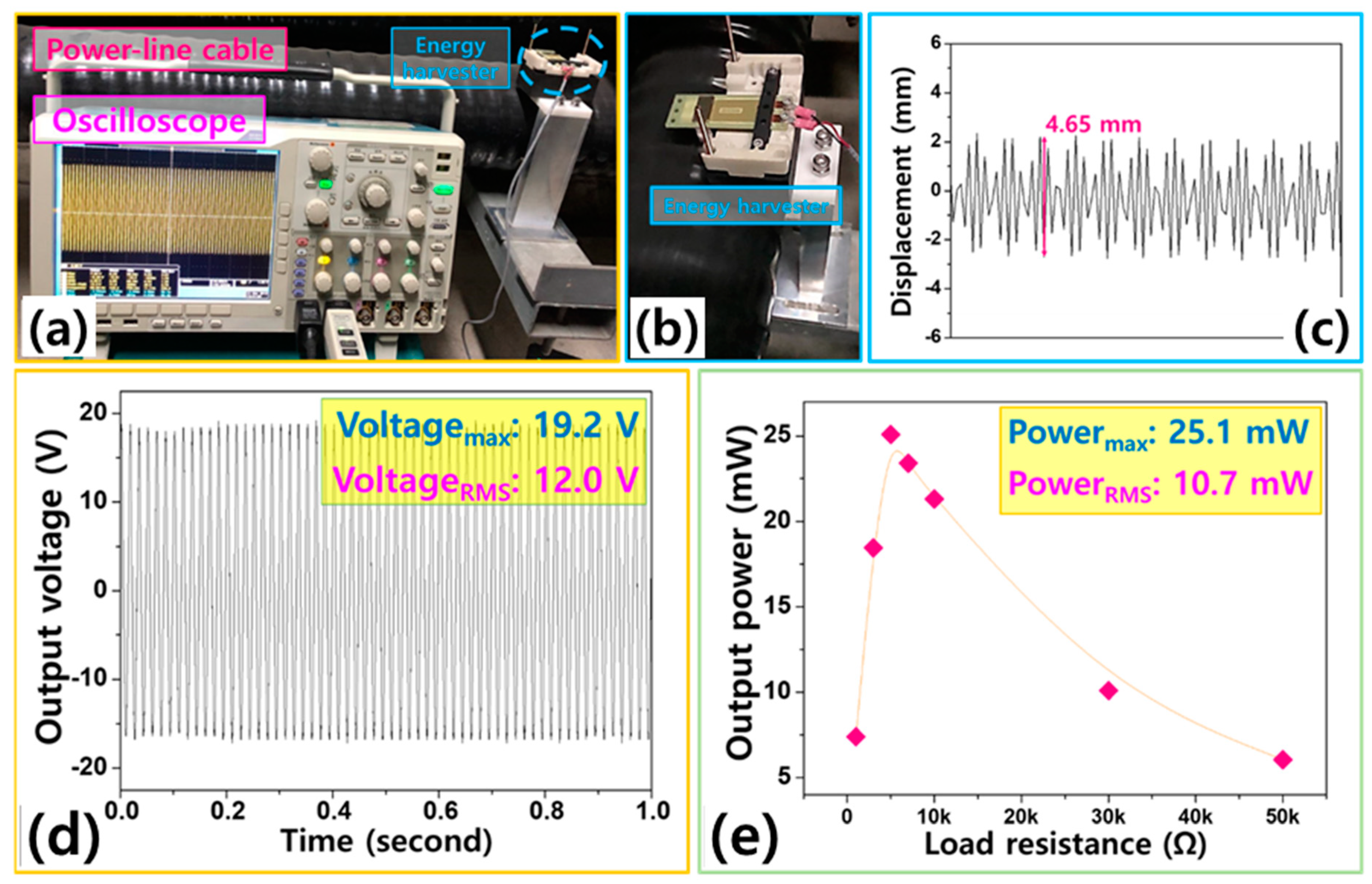
2.2. Demonstration of the MPEH around a Power-Line Cable

The South East Power Plant power-line cable (340 kV, 60 Hz), located at Youngheung, was used through a harvester to scavenge leakage magnetic field and current flow. The signals obtained from the wireless temperature sensor system (eZ430-RF2500T, Texas Instruments, Sherman, TX, USA) were transferred to a notebook computer via wireless RF signals. To demonstrate the method used to power the wireless sensor system, a 330 μF capacitor was charged to 7 V using the harvester. The charged voltage and sensing data were collected every 2.3 s during the demonstration.

2.3. Numerical Section

Finite element simulations were carried out in this study using the commercial software ABAQUS. The main purpose of finite element simulations is to numerically back up the experimental observations and to accurately predict the electromechanical behavior of the MPEH. The quadrilateral element, which has three displacement degrees of freedom per node (u1, u2, and u3 in the x, y, and z direction) was employed to model the piezoelectric material layer and substrate. By assuming that perfectly conductive electrodes completely coat each finite element on the top and bottom surfaces, the single electrical degree of freedom, which is the voltage across the electrodes, is adequate for simulating the electrical behavior. The cantilever-shaped finite element models for the piezoelectric energy harvester with ×1 layer, ×2 multilayers, and ×4 multilayers are displayed in Figure 2. For the piezoelectric ceramics layer, the quadratic brick element with one electrical degree of freedom (C3D20E) in ABAQUS was employed, while the quadratic brick element with 3 × 3 × 3 integration points (C3D20) was used for the substrates. The piezoelectric material properties listed in Table 1 were used in the current simulations.
The piezo-energy harvesters consist of one layer (70 × 25 × 0.70 mm3), two layers (70 × 25 × 0.714 mm3), and four layers (71 × 25.4 × 1.32 mm3) as indicated in Figure 2. The characteristics of the piezoelectric material used in the piezoelectric devices are shown in Table 1.

3. Results and Discussion

The generated voltages from the harvester with different magnetic fields were obtained from the finite element simulations, as shown in Figure 3. To define the magnetic field in the simulations, a magnetic vector potential boundary condition was employed in ABAQUS. The ×4 layers piezo-energy harvester was used for the simulations and the corresponding finite element model is shown in Figure 2c. As shown in Figure 3, the generated voltages increase as the magnetic fields increase, as do the maximum voltages. This result is in line with the experimental observation in Figure 4c. The maximum voltage value with the magnetic field of 80 μm was obtained as 62.9 at a frequency of 60 Hz, which is quite close to the experimental results.
Figure 4a shows the performance of the piezo-energy harvester under an AC magnetic field. The size of the piezo-energy harvester is ×4 layers (7.0 × 2.5 × 0.135 cm3), as shown in Figure 4b. The characteristics of the piezoelectric material used in the piezoelectric devices are shown in Table 1. Figure 4c shows the output voltage of the ×4 harvester according to the frequency of the AC magnetic field. Output performance from ×1, ×2, and ×4 harvesters under an AC magnetic field of 80 μT at 60 Hz, as can be seen in Figure S3 (see Supporting Information). As the magnetic field increased from 40 μT to 80 μT, the voltage of the harvester increased and reached an output voltage of 60 Vmax at a frequency of 60 Hz. In order to harvest a 60 Hz magnetic field using the piezo-energy harvester, the mass of the magnetic tip was adjusted through an attachment strategy. Because each energy harvester has a different elastic stiffness, a magnetic tip with a different mass is attached to the top and bottom of the beam. The mass change of the magnetic tip was found to be a factor causing some deformation of the resonance frequency of the MPEH. The experimental observation shown in Figure 4c was further supported by performing the steady-state dynamics (modal) analysis through the finite element simulations. The numerical results are displayed in Figure 3. Figure 4d shows the displacement of the tip mass and the output voltage of the ×4 harvester under various magnetic masses. The output voltage of 60.8 Vmax was observed when there were seven tip masses of 10 g each; this performance can be attributed to the increased mechanical stress due to the magnetic and weight conditions. In addition, the permanent magnet itself vibrates under magnetic field oscillation, where the magnetization phenomenon of the tip mass also contributes to the magneto-mechanical vibration, resulting in a higher electrical characteristic for the ×4 harvester. Using a magnet as a proof mass contributes to the force generated by the generator through the given force, determined as shown below. The power generated at the harvester is approximately proportional to the square of F m [22,23].
P = M 1 ω n × F m 2
Here, M 1 is the weight of the tip mass; ω n is the natural frequency; and F m is the force on the tip mass generated by the AC magnetic field.
Open-circuit voltage of the ×4 harvester generated 60.8 Vmax (36.7 Vrms) at a magnetic field of 80 μT for 10 s, as shown in Figure 4e. Output current of the ×4 harvester generated 5.54 mAmax (3.74 mArms) at a magnetic field of 80 μT for 10 s (see Figure 4f). The ×4 harvester was 215 mWmax (99 mWrms) at a load resistance of 5 kΩ, with the matching resistance changing according to the different internal impedances (see Figure 4g). The calculated power density of the ×4 harvester (cantilever: 7.0 × 2.5 × 0.13 cm3) was 94.5 mWmax/cm3 (43.5 mWrms/cm3) and that of the ×4 harvester (total module: 7.9 × 7.45 × 1.7 cm3) was 2.15 mWmax/cm3 (0.99 mWrms/cm3). At the magnetic field of 80 μT, the ×4 harvester was able to illuminate 972 commercial LEDs connected in parallel (see Figure 4h). This observation is further demonstrated through the finite element simulations, as shown in Figures S1 and S2 (see Supporting Materials).
Energy harvesters for generating energy from magnetic fields have been developed based on strong ME couplings. Piezo energy harvesters and magnetostrictive materials based on various combinations make use of simple harvesters to produce electricity from the magnetic fields dumped around them [26,27]. V. Annapureddy developed magnetic energy harvesters using PMN–PZ–PT and Ni plates. Through reduced energy losses, the maximum output power was measured of 2.1 mW/cm3 at 60 Hz. M. G. Kang developed energy harvesters, consisting of amorphous Fe85B5Si10 and a piezoelectric macrofiber composite (MFC) structure harvested energy of 9.8 mW and 125 mW/cm3 (see Table 2).
The experiment was conducted at the thermal power plant with power-line cables (see Figure 5a,b). The ×4 harvester was used to generate power from the actual magnetic field of the power-line cable (345 kV, 2000 A, ILJIN 2003), as indicated in Figure 5c. The magnetic field near the power-line cable was found to be a small one of 70–80 μT. Tip mass moves up and down due to the ambient magnetic field from the power-line cable.
A real photo of the experimental setup with an energy harvester for scavenging a magnetic field of an AC power-line cable (see Figure 6a,b). The displacement of the tip mass was 4.65 mm, as indicated in Figure 6c. Generated output voltage was 19.2 Vmax (12.0 Vrms) and output power was 25.1 mWmax (10.7 mWrms) at a load resistance of 5 kΩ (see Figure 6d,e). Utilizing the electric power generated by the magnetic field of the actual active power-line cable, it was possible to supply power to a wireless sensor network for a real-time monitoring system.
The conversion efficiency ( η ) of the ×4 harvester is determined by the proportion of energy collected by the magnetic layer, which is converted to electricity and expressed as:
η ( % ) = O u t p u t   p o w e r   ( P o u t ) I n p u t   p o w e r   ( P i n ) × 100
Input power ( P i n ) is related to the magnetic field energy spread through the cable [12]. The magnetic field collected by the ×4 harvester is related to the following equation:
P i n = 2 μ B 2 d x d y d z = 1 2 × B 2 μ × v × f
where the magnetic induction intensity is (B); v is the total volume of the harvester; and μ is the magnetic permeability and resonant frequency (f). In this situation, input power of the MPEH was 43.68 mW and output power (Pout) of the MPEH was 25.1 mW, so the energy harvester power efficiency was 36.5%. We found that the harvesting performance was heavily influenced by the structural elements of the elastomers, which varied with the number of layers. Using this high-efficiency module, the power generation characteristics were measured using the magnetic field from a power-line cable installed in an actual thermal power plant.
As mentioned earlier, powering a data transfer component of a wireless sensor node is a practical application of energy harvesting technology. Here, to assess the applicability of the developed harvester to IoT devices, we demonstrate how to use the power generated from a magnetic field energy around a power cable to power wireless sensors and data communication systems. Wireless sensor systems have been used for the wireless transmission of data from temperature sensors. Before turning on the sensor system, the harvester was connected to a simple circuit consisting of a rectifier, a 330 μF capacitor, a resistor, and a step-down converter to store enough electrical energy for system operation (see Figure 7a). The wireless sensor system is attached to the power-line cable and detects the ambient temperature while electricity is being delivered to the transformer. The electrical energy required to operate the system was tapped by energy harvesters placed on the power-line cable. After the harvester was charged to the capacitor for 3.8 s, the stored energy was applied to the wireless sensor system, which started to send temperature information to the laptop every 2.3 s. It was found that sufficient power is available to operate the wireless sensor system for 3.8 s (see Figure 7b). After operating the sensor system, the charged voltage dropped abruptly to approximately 4.8 V in approximately 1.6 s and the sensor system transmitted information. In the operating mode, the sensor system transmitted temperature information 16 times over a period of 40 s. The ambient temperature, measured from the ambient temperature of the power-line cable, ranged from 22.3 to 27.4 degrees, as shown in Figure 7c. Through this demonstration, we confirm the validity of the harvester and also confirm that it is applicable to power-line cables, which can be used as a ubiquitous power source to power IoT applications.

4. Conclusions

In conclusion, by using a multilayer piezoelectric structure harvester, we demonstrated a magnetic field energy harvesting device with improved harvesting properties. A permanent magnet tip mass was optimized to contribute to energy harvesting. The ×4 harvester was found to produce high output power of 215 mWmax (98 mWrms) at an AC magnetic field of 80 μT, sufficient to power a 972 LED array. Utilizing the magnetic field generated from a power-line cable used by the thermal power plant to determine the feasibility of the harvester, high output power levels of 25.1 mWmax (10.7 mWrms) were generated and used to charge a 330 μF capacitor in 3.8 s. This level of power was sufficient for IoT applications, as demonstrated by supplying power to a temperature sensor and a data communication system every 2.3 s. We will model the structure with improved power generation per unit area by increasing the number of layers and improving the properties of the piezoelectric materials and develop models with high magnetic performance to make a harvester that can be used in industrial appliances.

Supplementary Materials

Finite element results can be found in the Supplementary Materials. The following are available online at https://www.mdpi.com/article/10.3390/en14092387/s1, Figure S1: Numerical results of output voltage generated from finite element simulations in terms of (a) under unit force, (b) under 2 times unit force, (c) under 3 times unit force and (d) under 4 times unit force, Figure S2: Maximum voltage generated from ×1, ×2, and ×4 harvesters under various applied external forces, Figure S3: (a) Output voltage generated from ×1, ×2, and ×4 harvesters under AC magnetic field of 80 μT at 60 Hz for 10 s. (b) Maximum voltage generated from ×1, ×2, and ×4 harvesters under various AC magnetic field conditions at 60 Hz. (c) Maximum power with resistance changes generated from ×1, ×2, and ×4 harvesters under AC magnetic field of 80 μT at 60 Hz.

Author Contributions

Conceptualization, Q.W. and K.-B.K.; methodology, Y.S.; software, S.-B.W.; validation, Q.W. and S.-B.W.; formal analysis, Q.W. and K.-B.K.; investigation, Q.W. and K.-B.K.; resources, Q.W.; data curation, S.-B.W.; writing—original draft preparation, Q.W.; writing—review and editing, Q.W.; visualization, T.-H.S.; supervision, K.-B.K.; project administration, K.-B.K.; funding acquisition, T.-H.S. All authors have read and agreed to the published version of the manuscript discussion.

Funding

This work was funded by the Korea Institute of Energy Technology Evaluation and Planning (KETEP) and by the Ministry of Trade, Industry, and Energy (MOTIE) of the Republic of Korea (No. 2018201010636A).

Informed Consent Statement

Informed consent was obtained from all subjects involved in the study.

Data Availability Statement

The data presented in this study are available in the article or Supplementary Materials.

Acknowledgments

This work was supported by the Korea Institute of Energy Technology Evaluation and Planning (KETEP) and the Ministry of Trade, Industry & Energy (MOTIE) of the Republic of Korea (No. 2018201010636A).

Conflicts of Interest

The authors declare that they have no known competing financial interest or personal relationships that could have appeared to influence the work reported in this paper.

References

  1. Hosseinimehr, T.; Tabesh, A. Magnetic field energy harvesting from AC lines for powering wireless sensor nodes in smart grids. IEEE Trans. Ind. Electron. 2016, 63, 4947–4954. [Google Scholar] [CrossRef]
  2. Han, J.C.; Hu, J.; Yang, Y.; Wang, Z.X.; Wang, S.X.; He, J.L. A nonintrusive power supply design for self-powered sensor networks in the smart grid by scavenging energy from AC power line. IEEE Trans. Ind. Electron. 2015, 62, 4398–4407. [Google Scholar] [CrossRef]
  3. Bowen, C.; Kim, H.; Weaver, P.; Dunn, S. Piezoelectric and ferroelectric materials and structures for energy harvesting applications. Energy Environ. Sci. 2014, 7, 25–44. [Google Scholar] [CrossRef] [Green Version]
  4. Narendran, K.; Murali, K.; Sundar, V. Investigations into efficiency of vortex induced vibration hydro-kinetic energy device. Energy 2016, 109, 224–235. [Google Scholar] [CrossRef]
  5. Zhou, Z.; Qin, W.; Zhu, P.; Shang, S. Scavenging wind energy by a Y-shaped bi-stable energy harvester with curved wings. Energy 2018, 153, 400–412. [Google Scholar] [CrossRef] [Green Version]
  6. Ryu, J.; Kang, J.-E.; Zhou, Y.; Choi, S.-Y.; Yoon, W.-H.; Park, D.-S.; Choi, J.-J.; Hahn, B.-D.; Ahn, C.-W.; Kim, J.-W.; et al. Ubiquitous magneto-mechano-electric generator. Energy Environ. Sci. 2015, 8, 2402–2408. [Google Scholar] [CrossRef]
  7. Junlei, W.; Lihua, T.; Liya, Z.; Zhien, Z. Efficiency investigation on energy harvesting from airflows in HVAC system based on galloping of isosceles triangle sectioned bluff bodies. Energy 2019, 172, 1066–1078. [Google Scholar]
  8. Larkin, K.; Abdelkefi, A. Neutral axis modeling and effectiveness of functionally graded piezoelectric energy harvesters. Compos. Struct. 2019, 213, 25–36. [Google Scholar] [CrossRef]
  9. Han, J.C.; Hu, J.; Wang, Z.; Wang, S.X.; He, J.L. Magnetoelectric effect in shear-mode Pb(Zr,Ti)O3/NdFeB composite cantilever. Appl. Phys. Lett. 2015, 106, 182901. [Google Scholar] [CrossRef]
  10. Kim, K.B.; Cho, J.Y.; Jabbar, H.; Ahn, J.H.; Hong, S.D.; Woo, S.B.; Sung, T.H. Optimized composite piezoelectric energy harvesting floor tile for smart home energy management. Energy Convers. Manag. 2018, 171, 31–37. [Google Scholar] [CrossRef]
  11. Kausar, A.S.M.Z.; Reza, A.W.; Saleh, M.U.; Ramiah, H. Energizing wireless sensor networks by energy harvesting systems: Scopes, challenges and approaches. Renew. Sustain. Energy Rev. 2014, 38, 973–989. [Google Scholar] [CrossRef]
  12. Hou, L.; Bergmann, N.W. Novel industrial wireless sensor networks for machine condition monitoring and fault diagnosis. IEEE Trans. Instrum. Meas. 2012, 61, 2787–2798. [Google Scholar] [CrossRef]
  13. Manic, M.; Wijayasekara, D.; Amarasinghe, K.; Rodriguez-Andina, J.J. Building energy management systems: The age of intelligent and adaptive buildings. IEEE Ind. Electron. Mag. 2016, 10, 25–39. [Google Scholar] [CrossRef]
  14. Azevedo, J.A.R.; Santos, F.E.S. Energy harvesting from wind and water for autonomous wireless sensor nodes. IET Circuits Devices Syst. 2012, 6, 413–420. [Google Scholar] [CrossRef]
  15. Ding, Y.; Hong, S.H. CFP scheduling for real-time service and energy efficiency in the industrial applications of IEEE 802.15.4. J. Commun. Netw. 2013, 15, 87–101. [Google Scholar] [CrossRef]
  16. Wang, C.; Yanlong, C.; Jin, X. Piezoelectric and electromagnetic hybrid energy harvester for powering wireless sensor nodes in smart grid. J. Mech. Sci. Technol. 2015, 29, 4313–4318. [Google Scholar]
  17. Wei, H.; Ping, L.; Yumei, W.; Jitao, Z.; Aichao, Y.; Caijiang, L.; Jin, Y.; Jing, W.; Jing, Q.; Yong, Z.; et al. Piezoelectric energy harvester scavenging AC magnetic field energy from electric power lines. Sens. Actuators A 2013, 193, 59–68. [Google Scholar]
  18. Gillette, S.; Geiler, A.; Gray, D.; Viehland, D.; Vittoria, C.; Harris, V. Improved Sensitivity and Noise in Magneto-Electric Magnetic Field Sensors by Use of Modulated AC Magnetostriction. IEEE Magn. Lett. 2011, 2, 2500104. [Google Scholar] [CrossRef]
  19. Xing, Z.P.; Xu, K.; Dai, G.Y.; Li, J.F.; Viehland, D. Giant magnetoelectric torque effect and multicoupling in two phases ferromagnetic/piezoelectric system. J. Appl. Phys. 2011, 110, 104510. [Google Scholar] [CrossRef] [Green Version]
  20. Yan, Y.; Zhou, J.E.; Maurya, D.; Wang, Y.U.; Priya, S. Giant piezoelectric voltage coefficient in grain-oriented modified PbTiO3 material. Nat. Commun. 2016, 7, 13089. [Google Scholar] [CrossRef]
  21. Tadesse, Y.; Zhang, S.; Priya, S. Multimodal Energy Harvesting System: Piezoelectric and Electromagnetic. J. Intell. Mater. Syst. Struct. 2009, 20, 625–632. [Google Scholar] [CrossRef]
  22. Seo, I.T.; Cha, Y.J.; Kang, I.Y.; Choi, J.H.; Nahm, S.; Seung, T.H.; Paik, J.-H. High energy density piezoelectric ceramics for energy harvesting devices. J. Am. Ceram. Soc. 2011, 94, 3629–3631. [Google Scholar] [CrossRef]
  23. Ahn, C.-W.; Karmarkar, M.; Viehland, D.; Kang, D.-H.; Bae, K.-S.; Priya, S. Low-temperature sintering and piezoelectric properties of CuO-doped (K0.5Na0.5)NbO3 ceramics. Ferroelectr. Lett. 2008, 35, 66–72. [Google Scholar] [CrossRef]
  24. Harris, N.R.; Hill, M.; Torah, R.; Townsend, R.; Beeby, S.; White, N.M.; Ding, J. A multilayer thick-film PZT actuator for MEMs applications. Sens. Actuators A Phys. 2006, 132, 311–316. [Google Scholar] [CrossRef] [Green Version]
  25. Song, H.-C.; Kim, H.-C.; Kang, C.-Y.; Kim, H.-J.; Yoon, S.-J.; Jeong, D.-Y. Multilayer piezoelectric energy scavenger for large current generation. J. Electroceram. 2009, 23, 301–304. [Google Scholar] [CrossRef]
  26. Song, D.; Yang, C.H.; Hong, S.K.; Kim, S.B.; Woo, M.S.; Sung, T.H. Study on Application of Piezoelectricity to Korea Train eXpress (KTX). Ferroelectrics 2013, 449, 11–23. [Google Scholar] [CrossRef]
  27. Furlani, E.P. Permanent Magnet & Electromechanical Devices: Materials Analysis and Applications (Electromagnetism); Academic Press: San Diego, CA, USA, 2001. [Google Scholar]
  28. Annapureddy, V.; Kim, M.; Palneedi, H.; Lee, H.; Choi, S.-Y.; Yoon, W.; Park, D.; Choi, J.; Hahn, B.; Ahn, C.; et al. Low-Loss Piezoelectric Single-Crystal Fibers for Enhanced Magnetic Energy Harvesting with Magnetoelectric Composite. Adv. Energy Mater. 2016, 6, 1601244. [Google Scholar] [CrossRef]
  29. Annapureddy, V.; Na, S.M.; Hwang, G.-T.; Kang, M.G.; Sriramdas, R.; Palneedi, H.; Yoon, W.-H.; Hahn, B.-D.; Kim, J.-W.; Ahn, C.-W.; et al. Exceeding milli-watt powering magneto-mechano-electric generator for standalone-powered electronics. Energy Environ. Sci. 2018, 11, 818–829. [Google Scholar] [CrossRef]
  30. Cho, J.Y.; Kim, J.; Kim, K.B.; Ryu, C.H.; Hwang, W.; Lee, T.H.; Sung, T.H. Significant power enhancement method of magneto-piezoelectric energy harvester through directional optimization of magnetization for autonomous IIoT platform. Appl. Energy 2019, 254, 113710. [Google Scholar] [CrossRef]
  31. Kang, M.G.; Sriramdas, R.; Lee, H.; Chun, J.; Maurya, D.; Hwang, G.T.; Ryu, J.; Priya, S. High Power Magnetic Field Energy Harvesting through Amplified Magneto-Mechanical Vibration. Adv. Energy Mater. 2018, 8, 1703313. [Google Scholar] [CrossRef]
Figure 1. (a) Schematic of the magnetic field energy harvesting process using the piezo-energy harvester. (b) Photograph of the piezo-energy harvester for scavenging the magnetic field of AC power-line cable.
Energies 14 02387 g001
Figure 2. Finite element models of the piezoelectric energy harvesters with (a) ×1 layer, (b) ×2 layers, and (c) ×4 layers.
Energies 14 02387 g002
Figure 3. Finite element results of the maximum voltages according to the variations of magnetic field and frequency.
Energies 14 02387 g003
Figure 4. (a) Experimental apparatus for harvesting electric energy by adjusting magnetic field and frequency. (b) Harvester used in the experiment and size in detail. (c) Maximum voltage of harvester depending on the magnetic field and frequency. (d) Displacement and output voltage depending on the magnetic mass of harvester. (e) Open-circuit voltage generated from ×4 harvesters under an AC magnetic field of 80 μT at 60 Hz for 10 s. (f) Generated current generated from ×4 harvesters under an AC magnetic field of 80 μT at 60 Hz for 10 s. (g) Output power depending on load resistances. (h) We utilized electricity generated from the ×4 harvester to illuminate 972 LEDs.
Energies 14 02387 g004
Figure 5. (a) Photograph of the thermal power plant with power-line cable. (b) Actual photo of power plant with power-line cables. (c) Photograph of the 345 kV power-line cable installed at the power plant.
Energies 14 02387 g005
Figure 6. (a) Actual photo of the experimental setup with a ×4 harvester with the actual magnetic field of a power-line cable. (b) Photograph of the piezo-energy harvester for scavenging the magnetic field of an AC power-line cable. (c) Displacement (mm) of the tip mass under an ambient magnetic field from the power-line cable. (d) Output voltage (V) of the ×4 harvester generated by the magnetic field of power-line cable. (e) Output power (mW) of the ×4 harvester generated under various load resistances.
Energies 14 02387 g006
Figure 7. (a) Electrical circuit for powering the wireless sensor and data transmission system utilizing the magnetic field generated from the power-line cable of the power plant. (b) Graph of the current drawn from power-line cable of the power plant, charged to 330 μF through the harvester, and measured the temperature data obtained using the charged energy. (c) Graph measured from the ambient temperature of the power-line cable ranging from 22.3 to 27.4.
Energies 14 02387 g007
Table 1. Characteristics of the piezoelectric materials used in the piezo-energy harvester.
SampleDielectric ConstantCapacitance
(nF)
d 33
(10−12 m/V)
d 31
(10−12 m/V)
g 33
(10−3 Vm/N)
kp d 33 × g 33
(10−12 m2/N)
PZT-5H380097650−320190.7512,350
Table 2. Comparison of output performances of existing magneto energy harvesters.
Energy HarvesterOutput Voltage
(V)
Output Power
(mW)
Power Density
(mW/cm3)
Frequency
(Hz)
Ref.
Ni/low-loss PMN24-2.160[28]
Ni/PMN 2.5 - 0.04660[6]
Fe–Ga SCMF 76.5 - 3.2260[29]
MPEH 60.8 215 94.560This work
FBS/MFC - 9.8 12560[30]
PZT-5H - 39.2 19.660[31]
Publisher’s Note: MDPI stays neutral with regard to jurisdictional claims in published maps and institutional affiliations.

