Article

Physical Dimensions as a Design Objective in Heat Transfer Equipment: The Case of Plate and Fin Heat Exchangers  †

by
Jorge García-Castillo
1 and
Martín Picón-Núñez
2,*
1
Department of Environmental Sciences, Division of Life Sciences, University of Guanajuato, El Copal km 9, Irapuato 36500, Mexico
2
Department of Chemical Engineering, Division of Natural and Exact Sciences, University of Guanajuato, Noria Alta S/N, Guanajuato 36050, Mexico
*
Author to whom correspondence should be addressed.
This paper is an extended version of our paper published in Conference on Process Integration, Modelling and Optimisation for Energy Saving and Pollution Reduction—PRES 20, Xi’an Jiaotong University, China, from 17th to 21st August 2020; CET 2020, 81, 559–564.
Energies 2021, 14(8), 2318; https://doi.org/10.3390/en14082318
Submission received: 8 March 2021 / Revised: 3 April 2021 / Accepted: 7 April 2021 / Published: 20 April 2021

Abstract

:
To incorporate exchanger dimensions as a design objective in plate and fin heat exchangers, a variable that must be taken into consideration is the geometry of the finned surfaces to be used. In this work, a methodology to find the surface geometry that will produce the required heat transfer coefficient and pressure drop to achieve the design targets was developed. The geometry of secondary surfaces can be specified by the fin density, which represents the number of fins per unit length. All other geometrical features, as well as the thermo-hydraulic performance, can be derived from this parameter. This work showed the way finned surfaces are engineered employing generalised thermo-hydraulic correlations as a part of a design methodology. It also showed that there was a volume space referred to as volume design region (VDR) where heat duty, pressure drop, and dimensions could simultaneously be met. Such a volume design region was problem- and surface-specific; therefore, its limits were determined by the heat duty, the pressure drop, and the type of finned surface chosen in the design. The application of this methodology to a case study showed that a shell and tube heat exchanger of 227.4 m2, with the appropriate fin density using offset strip-fins, could be replaced by a plate and fin exchanger with any combination of height, width, and length in the ranges of 0–0.58 m, 0–0.58 m, and 0–3.59 m. The approach presented in this work indicated that heat exchanger dimensions could be fixed as a design objective, and they could effectively be achieved through surface design.

1. Introduction

The possibility of using many different types of secondary surfaces in design gives plate and fin heat exchangers a flexible degree of freedom to incorporate exchanger dimensions as a design objective, as shown in this paper. These types of exchangers were originally developed for gas-to-gas applications, but the development of the manufacturing techniques such as direct metal laser sintering (DMLS) made them suitable to process high pressure and temperature fluids [1]. They can also be fabricated using almost any kind of material to withstand highly reactive and corrosive environments [2].
The thermal performance of plate and fin exchangers depends mainly on the thermo-hydraulic characteristics of the secondary surfaces employed. Amidst, the most common types of finned surfaces are plain, perforated, wavy, offset, and louvered. They are characterised by a large surface area in a relatively small volume resulting in small hydraulic diameters and consequently low Reynolds numbers. There exist many types of surfaces but still, new shapes continue to appear in the search of higher heat transfer performance with lower pressure drop consumption [3].
The selection of a finned surface is a key issue in the design of plate and fin exchangers as they determine the size and shape of the unit. The following observations can be made about the impact of the surface choice on the exchanger shape: 1.—high-performance surfaces tend to produce smaller volumes with a combination of large frontal areas and small flow lengths; 2.—low-performance surfaces result in larger volumes with small frontal areas and large flow lengths [4].
The thermal performance of finned surfaces is commonly reported on in terms of the Colburn factor (j); this term conveniently represents the heat transfer between plates in laminar or turbulent flow and for fluids covering Prandtl numbers between 0.6 and 100. Available correlations showed to apply well even for low-temperature applications such as those found in cryogenic processes, as demonstrated by Jiang et al. [5]. The applicability of the Colburn factor expressions to cover liquids and gases was demonstrated by the experimental work reported by Yang et al. [6], who determined the thermo-hydraulic performance of plate and fin exchangers using air and water, finding that the Colburn factor provided accurate thermal performance predictions for both fluids. Additionally, new techniques such as artificial neural networks were applied to determine the heat transfer performance from experimental data, as demonstrated by Aasi and Mishra [7].
One of the first published manographs containing experimental data of different types of secondary surfaces was reported in [8]. Since then, many other experimental data and semiempirical correlations have been published, covering a wide variety of surface geometries [9]. New designs emerged in the attempt to produce an improved thermo-hydraulic performance, such as the V-shape oblique wavy fins [10]. Studies employing higher density surfaces demonstrated a superior heat transfer performance [11], and yet the use of compact surfaces in two-phase flow has been an important area of development due to the many applications at low temperatures, as reported by Hu and Li [12].
Due to a large number of new finned surfaces available, there has been a need to develop selection procedures in design. The purpose of such methods is to provide information to lead the designer to choose the surface that exhibits the highest thermo-hydraulic performance. Wang et al. [13] described the use of two comparison methods, the performance evaluation criteria (PEC) based on the ratio of the Nusselt number and the friction factor for a given Reynolds number, and the field synergy number (Fc) represented by the Stanton number (Nu/Re Pr). These methods were useful tools to lead the design towards smaller exchanger volumes with reduced pressure drops.
The implementation of optimisation approaches in the design of plate and fin heat exchangers represented a power tool for the development of new surface types. For instance, Bianco et al. [14] applied multi-objective optimisation approaches to find the surface geometries that maximised the heat rate and minimised the pressure drop. Other optimisation approaches considered different parameters, such as the minimum entropy generation, where the minimisation of the term was the consequence of increased heat transfer coefficients and reduced pressure drop [15]. Optimisation was also applied to choose the best surface amidst the pool of options currently available for design, as demonstrated by Kunpeng et al. [16]. When more than one objective was established, multi-objective optimisation approaches applied to plate and fin exchangers focused mainly on the search of the surface that rendered minimum volume, weight, and cost [17]. Ramezanpour et al. [18] looked at the optimal design of plate and fin exchangers for multifluid applications. To find the design with the minimum total annual costs, they established fin density as the main decision variable and other geometrical parameters as secondary decision variables. On a different approach, CFD techniques were used to produce design information in combination with genetic algorithms to optimise volume and thermal effectiveness using offset strip-fins [19]. Yu et al. [20] employed wavy fins to generate exchanger data from CFD simulations and applied multi-objective optimisation with genetic algorithms to find values of Colburn and friction factors to yield the minimum cost. Li et al. [21] demonstrated that the fin geometry was linked to the thermo-hydraulic performance of a heat exchanger. They put an optimisation approach forward to find the fin height, fin space, fin interrupted length, and fin thickness of offset strip-fins to achieve maximum heat transfer and minimum pressure drop in a plate and fin exchanger based on thermal potential energy or entransy theory.
In the works where design was obtained by optimisation, the drive was normally to find the exchanger dimensions that minimised total operating costs, volume, or weight. If the aim of the design was set differently, for example, if the object of the design was to achieve certain fixed dimensions, then, in principle, optimisation was not the priority. The problem now was how to achieve the heat duty, pressure drop, and exchanger geometry simultaneously. The only way in which these three design objectives could be reconciled was by finding the proper surface geometry. The purpose of this work was to introduce the methodology for surface design to determine the geometrical parameters that fulfil the three objectives. The approach identified the required thermo-hydraulic performance from where the actual fin geometry was found.
The linking of thermo-hydraulic performance to the actual surface geometry gave rise to new surfaces which most likely will not be commercially available. Such issues could be overcome by considering new manufacturing procedures such as special additive manufacturing techniques known as selective laser melting (SLM). Tariqa et al. [22] applied this technique to the manufacturing of novel fins with perforations and slots through the plate fins.
Due to the discrete nature of the available geometry of secondary surfaces, most design approaches made use of a surface selection algorithm [23]. An approach to the design of secondary surfaces to meet specific thermo-hydraulic needs was presented in [24]. In that work using generalised correlations, a set of curves for the heat transfer and pressure drop of different surface geometries were produced with the aim of finding, by interpolation, the specific geometry that would produce the expected thermal and hydraulic performance. This methodology was further explored and used in the design of multi-stream heat exchangers [25].
For the purpose of designing new surfaces, the existence of generalised correlations as a function of the fin geometry was essential. Chennu [26] reported thermo-hydraulic performance correlations for finned surfaces as a function of the fin geometry. Such expressions provided the basis for the study introduced in this work, in which the specific fin geometry to attain a desired thermo-hydraulic performance was determined. Additionally, the concept of the volume design region (VDR) was developed to show the spatial region depicted by the maximum height, width, and length, where any heat exchanger dimensions could be attained for a given design problem. The main assumption underlying this statement was the consideration that the fin dimensions were continuous over a range of fin densities. To describe the methodology, this work was organised as follows: first, the principles for surface design and the description of the main geometrical features of triangular, rectangular, offset, and louvered surfaces were presented. Then, the thermal model for exchanger sizing and the volume design region were explained. Finally, the design approach was demonstrated in a case study.

2. Surface Engineering

Surface engineering consists of the search of the fin geometry that produces a desired thermo-hydraulic performance for a given operating data. From the general design equation, the volume of a plate and fin exchanger VT (m3) can be expressed as a function of three parameters: heat duty; Q (W), the temperature-driving forces represented by the logarithmic mean temperature difference, ΔTLM (K); and the overall heat transfer coefficient, U (W/m2 K):
V T = f ( Q ,   Δ T L M ,   U )
For a given design problem where the heat duty, the temperature driving forces, and the exchanger dimensions (or volume) were fixed, the overall heat transfer coefficient that meets all these conditions could be computed. The contribution of each of the streams involved in the heat exchange process to the overall heat transfer coefficient was obtained from the fin temperature effectiveness (ηo); the heat transfer coefficient, h (W/m2 K); and the total surface area, A (m2). If a new surface was defined using a fin density, the thermo-hydraulic performance could be calculated using generalised correlations expressed as a function of fin geometrical parameters and the Reynolds number.
Generalised expressions to calculate the thermo-hydraulic performance of different surfaces as a function of the fin geometry had been published by different authors. Out of the different types of existing secondary surfaces, this work explored four: triangular plain fin, rectangular plain fin, louvered, and offset.
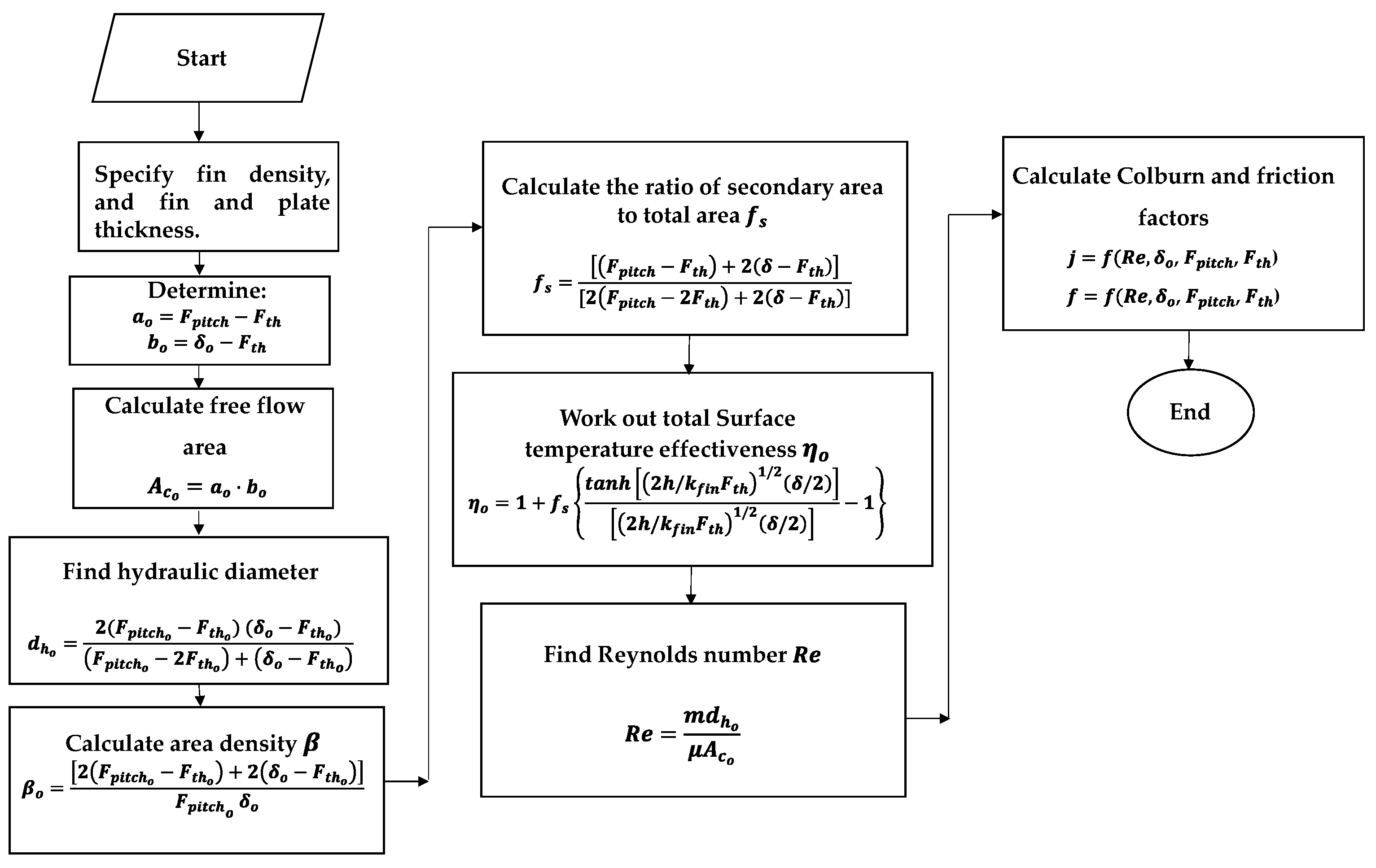
Before the design procedure is outlined, it was important to establish the geometrical expressions that allowed the specification of a finned surface as a function of fin density. Surface geometrical parameters that determine the performance of secondary surfaces were the free flow area, Ac (m2); the hydraulic diameter, dh (m); the area density, β (m2/m3); and the ratio of the secondary area to total surface area, fs (1). They could be calculated from the specification of fin height and fin pitch. Figure 1 shows the main geometrical dimensions that determine the thermo-hydraulic performance of triangular, rectangular, offset, and louvered surfaces.
The hydraulic diameter is a function of the free flow area and is determined as:
d h = 4   A c / P w
where Ac (m2) is the free flow area and P w ( m ) is the wetted perimeter. In plate and fin heat exchangers, the total heat transfer area per unit volume is greater compared with other technologies; this feature is referred to as area density, β (m2/m3). The ratio of the total surface area to the volume of that side of the exchanger (β) is calculated as:
β = A s i d e   1 / V s i d e   1
The term fs (1), which is the ratio of the secondary surface area to the total surface area for triangular fins, can be calculated as:
f s = ( δ t F t h t ) / c o s θ t [ ( a t F t h ) + ( δ F t h ) / c o s θ ]
where a t (m) is half of the base of the triangular fin and θ t is the characteristic angle (°). One parameter used in the design that relates the surface area of one side, Ai (m2), to the total volume of the unit, VT (m3), is represented by the term α   ( m 2 / m 3 ) and is calculated as [27]:
α i = A i / V T   ; i = 1 ,   2
The term i denotes the hot and cold sides. For each side, α is calculated from the geometrical characteristics of the type of surface employed:
α i = β i   [ δ i / ( δ 1 + δ 2 + 2 F t h ) ]   ; i = 1 , 2
where δ (m) is the plate spacing. Table 1 shows the expressions derived for the free flow area and hydraulic diameter, and Table 2 those for the ratio of secondary surface area to total area and area density for the four fin types used in this work.
The total surface temperature effectiveness, ηo (1) can be determined from [8]:
η o = 1 f s   ( 1 η f )
where:
η f = t a n h [ ( 2 h / k f i n F t h ) 1 / 2 ( δ / 2 ) ] [ ( 2 h / k f i n F t h ) 1 / 2 ( δ / 2 ) ]
The term δ / 2 (m) is the fin effective length, that corresponds to half the plate spacing or the midpoint between two adjacent thermal plates. Substitution of Equations (4) and (24) into (23), and rearranging gives:
η o = 1 + f s { t a n h [ ( 2 h / k f i n F t h ) 1 / 2 ( δ / 2 ) ] [ ( 2 h / k f i n F t h ) 1 / 2 ( δ / 2 ) ] 1 }
The connection between the geometrical features and the thermo-dynamic performance could be derived from the exchanger design equation making the following assumptions:
  • Steady-state operation
  • Continuous fin geometrical variables
  • Single-phase heat transfer process
  • Constant fluid properties
  • Adiabatic operation
  • Negligible longitudinal conduction effects
  • Uniform heat transfer coefficient
  • Uniform flow distribution
The expression to determine the exchanger volume could be derived from the general equation for the design of a heat exchanger.
Q = U   A   F   Δ T L M
where U (W/m2 K) is the overall heat transfer coefficient, A (m2) is the total surface area, F (1) is the correction factor of the logarithmic mean temperature difference, and Δ T L M   ( K ) is the logarithmic mean temperature difference.
When expressing the overall heat transfer coefficient in terms of the thermal resistances, and substitution of Equation (5) into the heat transfer expression and for a counter-current arrangement (F = 1), the resulting expression is:
V T = Q   Δ T L M   [ 1 ( η o h α ) 1 + R f 1 + 1 ( η o h α ) 2 + R f 2 ]
where Rf1 and Rf2 (m2 K/W) are the resistance to heat transfer due to fouling on streams 1 and 2, and h (W/m2 K) is the heat transfer coefficient. The values of the heat transfer coefficients can be obtained from the Colburn factor, j (1) that is expressed as:
j = S t   P r 2 / 3
S t   (1) is the Stanton number, and P r (1) is the Prandtl number defined as:
S t = h   A c / m C p
P r = C p   μ / k
where m   ˙ (kg/s) is the mass flow rate, Cp (J/kg K) is the heat capacity, μ (kg/m s) is the viscosity, and k (W/m K) is the thermal conductivity. Introducing Equations (29) and (30) into Equation (28) and solving for the convective heat transfer, it follows that:
h = j m C p A c P r 2 / 3
Expression (31) shows the convective heat transfer as a function of the Colburn factor, flow conditions, fluid properties, and free flow area of the secondary surface. The free flow area for the secondary surface depends on the type of fin used. The pressure drop, ΔP (Pa), due to friction across the core of the heat exchanger is expressed by:
Δ P = 2 f L   m 2 ρ d h A c 2
where f (1) is the friction factor, ρ (kg/m3) is the fluid density, and L (m) is the flow length. From Expression (27), the thermo-hydraulic contribution of the streams to the clean overall heat transfer coefficient is:
1 U = 1 ( η 0   h   α ) 1 + 1 ( η 0   h   α ) 2
As mentioned earlier, when the heat duty, temperature driving forces, and the exchanger dimensions were fixed, the value of U (W/m2 K) could be determined. This value corresponded to the thermo-hydraulic performance that must be fulfilled to achieve the given dimensions. Figure 2 shows a block diagram of the surface design approach proposed in this work. For each stream, the larger the value of ηo (W/m3 K), the larger the pressure drop. The overall approach to determine the fin geometry that gave the desired thermo-hydraulic performance is outlined in Figure 2.

3. Choice of Generalised Correlations

A key step in the use of generalised correlations was the evaluation of their accuracy by comparing their prediction with the experimental data reported in the literature. The validation procedures started by choosing commercial surfaces with their geometrical features such as fin density, plate spacing, fin thickness, and area density, along with their Colburn and friction factor information. The experimental data were then compared with the values obtained with the generalised correlations. Table 3 shows the generalised correlations for heat transfer and friction correlation used in this work.
The experimental data of commercial surfaces reported in [8] were compared with the generalised correlations. For example, Figure 3 shows the case of the offset strip-fin 1/8-15.2 against correlations (41) and (45).
In most cases, the comparison between experimental data and generalised correlations showed a zone of overprediction and another of underprediction while the friction factor tended to be underpredicted. This indicated that in designs that resulted in Reynolds numbers below 2000, the design would be smaller than needed. This was an unsafe design zone. The opposite occurred with designs with Reynolds numbers above 2000, here the design would be slightly larger with smaller pressure drops.
Table 4 shows the comparison between experimental data [8] and the correlations given by Equations (41) and (47) for the strip-fin 1/8-15.2 surface for different Reynolds numbers. The simple error deviation (Dev) from the experimental result for the Coburn and friction factor is calculated from:
D e v j = J e x p J C o r r J e x p · 100   [ % ]
D e v f = f e x p f C o r r f e x p · 100   [ % ]
The standard deviation (Std) is computed from:
S t d D e v j = ( D e v j D e v ¯ j ) 2 ( n 1 )
S t d D e v f = ( D e v f D e v ¯ f ) 2 ( n 1 )
where D e v ¯ f is the average error and n (1) is the number of elements.
In Table 5, the performance of the 15 different surfaces reported in [8] are analysed, and the average standard deviation is obtained after comparison with correlations are reported.
Apart from surface 1/9-22.68, the predicted heat transfer and friction performance of all the other surfaces was within an acceptable value. This result indicated that the design results obtained in this work must be taken with caution; however, this did not invalidate the design approach but simply confirmed that there is still research to be done to develop improved generalised correlations to predict the thermo-hydraulic performance of secondary surfaces as a function of the fin geometry.

4. Volume Design Region

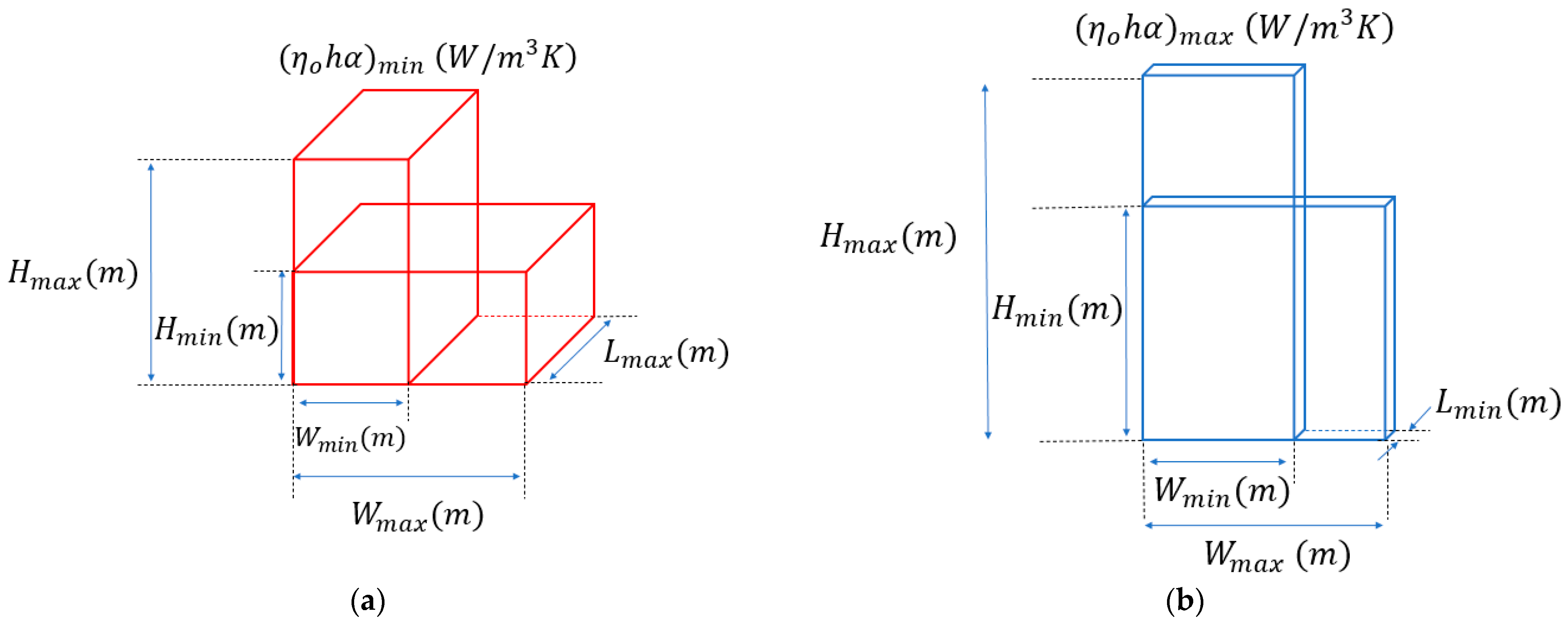
A volume design region (VDR) represented the volume space where a feasible heat exchanger exited and was characterised by minimum and maximum volume boundaries. The key variable that controlled the dimensions of the VDR was the fin density or number of fins per inch in the flow direction. In consequence, the minimum volume was obtained for the highest fin density, while the largest volume was obtained for the lowest density fin. There was another element to consider in the definition of a volume design region. It was related to the shape of the exchanger that was defined by the frontal area and the flow length.
As mentioned above, in the design of a heat exchanger, the type of secondary surface employed determined the shape and dimensions of the exchanger. In general, surfaces tend to create higher local turbulence at the expense of the pressure drop (offset and louvered), exhibiting higher performance than plain surfaces (triangular and rectangular). Within each type of surface, fin density will move the performance to higher or lower volumes. In terms of fin density, the two limiting conditions (higher and lower) were defined as a function of the fin opening in the flow direction. In this work, it was assumed that the highest fin density occurred when the variables approximated the fin thickness, which was when a t = a l = F t h   ( m ) for triangular and louvered fins, and a r = a o = 2 F t h   ( m ) for rectangular and offset fins. On the other hand, a low-density surface was obtained when the fin density or number of fins per inch equalled 1.
Once the surface geometry had been decided on, the next step in the design was to decide on the stream that maximised the use of the allowable pressure drop. To this end, it was important to recognise that, in a pure counter-current arrangement, only one of the streams could fully absorb the pressure drop allocated for the design. In other arrangements, such as the crossflow, both streams could fully absorb their pressure drop [27]. For a given surface geometry, the pressure drop determined the flow length and free flow area.
When the surfaces used in the design of a heat exchanger both exhibited a high-density, the design produced the minimum volume; a low-density surface used in both streams gave the maximum unit volume. To demonstrate the concept of the volume design region, in the example below, the maximum and minimum volumes were calculated using the same surface type and same surface density on a two-stream problem. The volume design region was calculated for triangular, rectangular, offset strip-fin, and louvered surfaces. Figure 4 depicts the volume design region where it was shown that various aspect ratios (height divided by width) could be obtained. In industrial applications, it is common to be constrained by space limitations; usually, those limitations are stricter in the horizontal direction because it is common to have more equipment close to the unit. The height of the unit was a more flexible variable due to the availability of space in the vertical direction. Defining the aspect ratio, AR (1), as the height of the unit, H (m), divided by the exchanger width, W (m), it was advantageous to use the width as a degree of freedom to produce the desired aspect ratio.
The design methodology used to obtain a given frontal aspect ratio started with the selection of the type of secondary surfaces for the streams. Then, the heat exchanger width, W (m) was set. In this step, for a given fin density, the numbers of fins contained within the width W were determined. Using the correlations, the Colburn and friction factors were calculated and then, the convective heat transfer was calculated for both the hot and cold stream. Finally, the exchanger volume was computed from the known thermal load, Q (W), flow arrangement (F = 1), and the total fin effectiveness η o (1).
For a deeper understanding of the design approach, it was important to appreciate the link between operating and geometrical variables. In a counter-current unit, the exchanger dimensions depended on how the pressure was distributed between the fraction absorbed by the fluid velocity and the fraction absorbed by the flow along the length. The fluid velocity was determined by the free flow area. These two terms are related by:
L = V / W H
For a fixed flow length, the free flow area was computed. In a counterflow arrangement, the flow length was the same for both streams, so if the free flow area of one stream was fixed, and this fixed the free flow area of the other. Then, the number of passages per stream and the total heat exchanger height, H T (m), is calculated as follows:
H T = N p 1 P s p 1 + N p 2 P s p 2 + ( N p 1 + N p 2 + 1 ) P t h
where HT (m) is the exchanger height, Np1 (1) and Np2 (1) are the number of channels of stream 1 and 2, Psp1 (m), Psp2 (m) are the plate spacings, and Pth (m) is the plate thickness.

5. Case Study

Table 6 presents the operating and physical property data of a design problem taken from the literature [30], where methanol was cooled in a 227.4 m2 shell and tube exchanger. A plate and fin exchanger were to be designed for this same application. The volume design region (VDR) in which a feasible design existed for different surfaces was obtained. The fin thickness Fth (m) and plate thickness Pth (m) used for the problem were 0.0003 m and 0.002 m, and the plate spacing ( δ ) was 0.0065 m. The heat exchanger design was obtained for triangular, rectangular, offset, and louvered surfaces. In each design, the same surface was used on both the cold and hot streams.
The heat exchanger volume and the design results are shown in Table 7. For each type of surface, the two columns represented the design using the lowest and highest fin density. The volume design region depended on the operating conditions and the fin-type employed. In the high-density case, the rectangular fins gave the lowest and the largest volume for both the high and lower density case, with the following values: V T = 0.012   m 3 and V T = 3.371   m 3 .
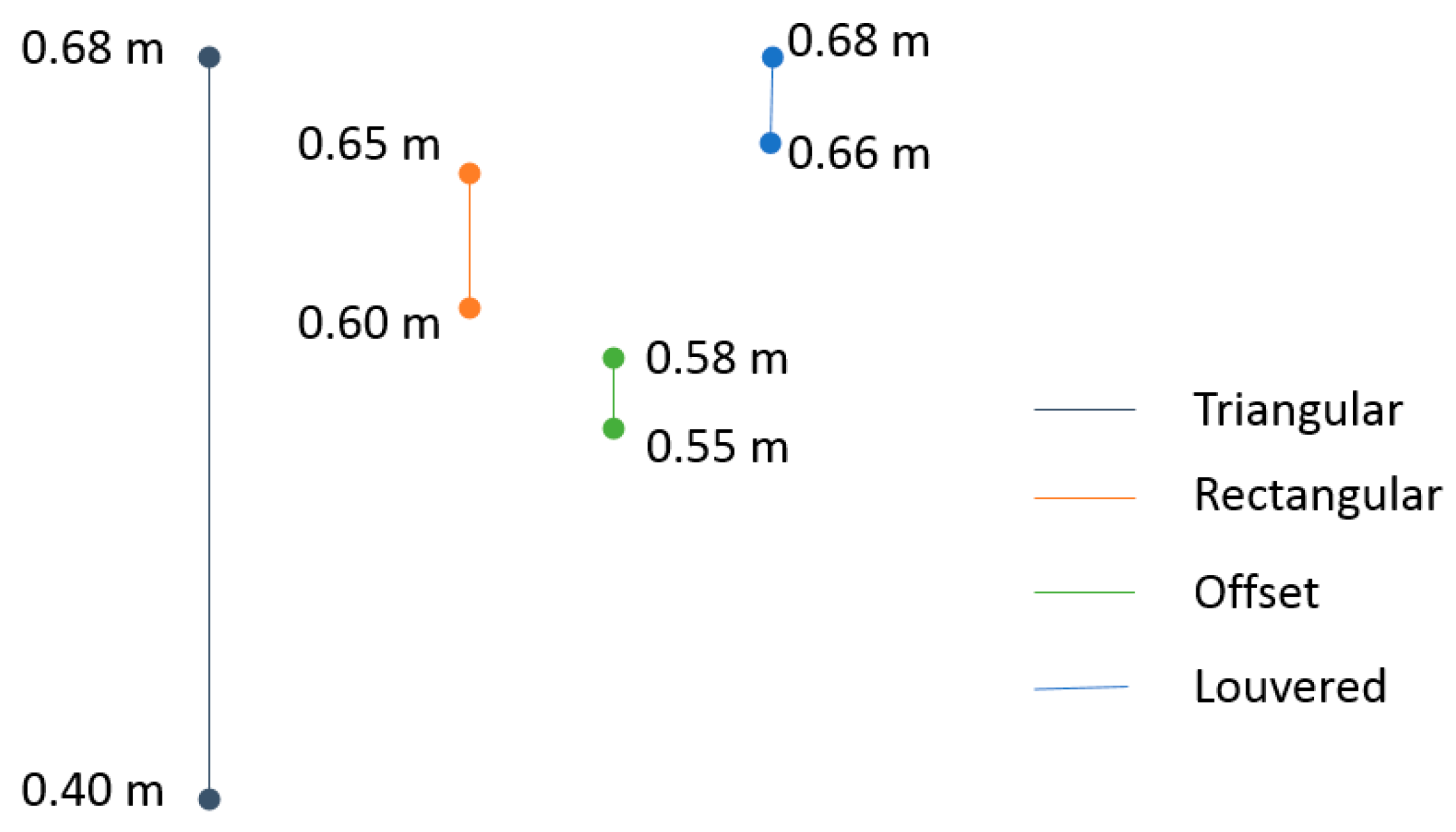
Using triangular surfaces, the smallest and largest volumes were V T = 0.035   m 3 and V T = 1.96   m 3 . The flow length that corresponded to the minimum volume was L = 0.09 m, and the free flow area was 0.06 m2, while the maximum volume was L = 14.73 m and the free flow area was 0.058 m2. Fixing an aspect ratio for frontal dimensions of 1, any heat exchanger width between W = 0.4 m and 0.66 m could be achieved if the fin density was modified accordingly. With the use of the louvered surfaces, the volume boundaries were V T = 0.045   m 3 and V T = 1.68   m 3 . In the case of flow length and free flow area, the feasible ranges went from 0.28 m to 4.25 m and from 0.12 m2 to 0.19 m2.
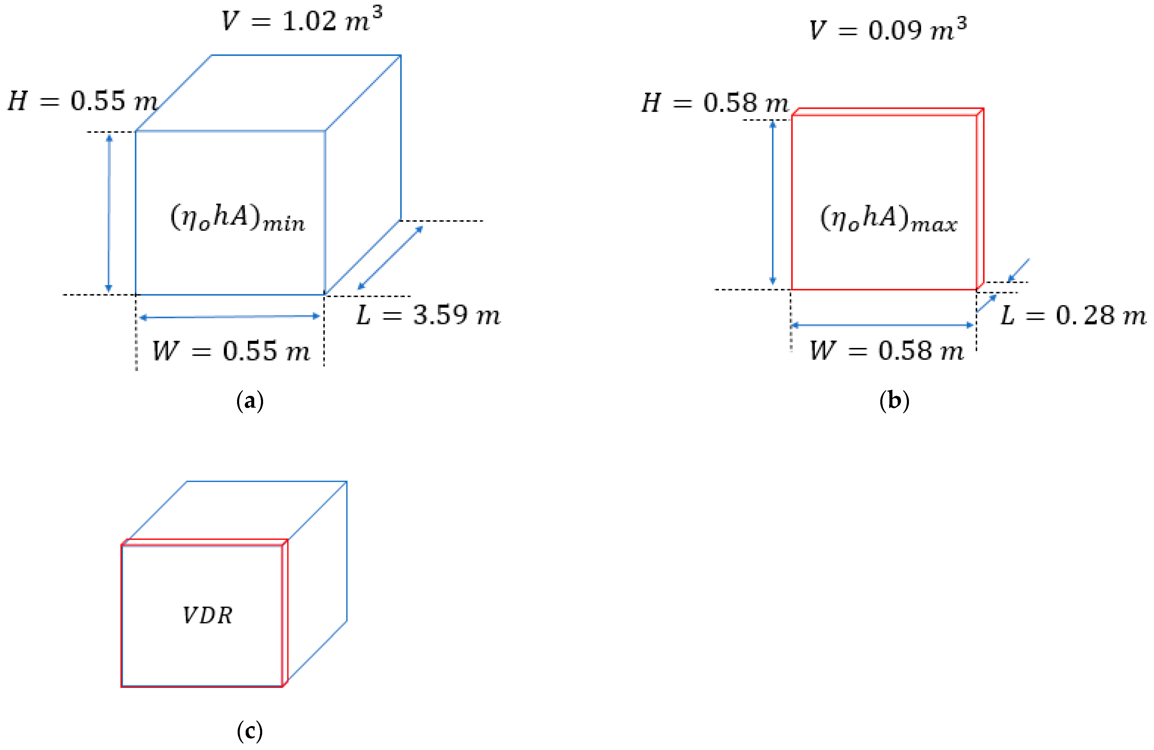
Finally, for the offset strip-fin, the volume boundaries were V T = 0.09   m 3 and V T = 1.02   m 3 . To achieve an aspect ratio of 1, the width could only be modified within the range of W = 0.58 m to 0.55 m. The corresponding lengths and free flow areas were L = 0.28 m and 0.10 m2 and L = 3.59 m, and the free flow area was 0.13 m2. Figure 5 shows the volume design region for the case of study using offset strip-fins.

6. Discussion

In this case study, the highest fin density had a value of 28.2 fins per inch, and the lowest fin density was equal to 1. In practice, the minimum and maximum fin densities would depend on the specification of the fin thickness. The frontal area of the heat exchanger was strongly linked to the fluid properties and the allowable pressure drop levels. In terms of the boundaries for the fin density, only the triangular and strip-fin surfaces were constrained in their lowest values. For a given allowable pressure drop and a given width, the use of smaller fin densities increased the volume of the unit and the flow length, causing a reduction in the heat exchanger height. In the case of a triangular and offset strip-fin, for a fin density lower than 4 and 5, the Reynolds number exceeded the range of validity of the available correlations.
As mentioned above, the specification of the plate width fixed the plate height; with this, the shape of the frontal area (aspect ratio) could be accommodated to the desired dimensions. For a near 1 aspect ratio, Figure 6 depicts the upper and lower limits for a feasible solution for the different fin types. The information in the diagram showed that certain width values could be achieved by proper selection of the fin-type. For instance, if it was desired to have an exchanger width between 0.55 m and 0.58 m, such dimension could only be achieved using triangular and offset fins.
It is important to mention that the frontal dimensions corresponded to the limit conditions in terms of fin density. It was possible to obtain a larger frontal area, i.e., W = 0.75, m by the variation of the fin density on both streams. The VDR and the allowable pressure drop controlled the dimensions of the unit.
For a width W = 0.75 m, an analysis of the variation of the heat exchanger height and length as a function of fin density was carried out. Figure 7a shows the case of the maximised pressure drop (cold stream). As could be seen, when the fin density increased, the height also increased, but the flow length was reduced. When the fin density increased the pressure drop across the heat exchanger also increased; in this sense, the fin density controlled the heat exchanger dimensions. Then, the fin density could be chosen so that the required dimensions were satisfied without compromising the length in terms of space limitations.
For a design exhibiting a width of 0.75 m and a height of 0.75 m, the use of offset fins would require that 7.6 fins per inch were used for the cold stream and 20 fins per inch on the hot side. For other surface types, the results are given in Table 8.
The design approach shown in this work had a sound theoretical background based on the basic principle that the size of a heat exchanger depends on the overall heat transfer coefficient, which, in turn, results in the heat transfer performance of the stream exchanging heat in the unit. The contribution of this work lay in the search for the means of controlling the heat transfer coefficient. As demonstrated in the work, in the case of plate and fin exchangers this could be achieved by designing secondary surfaces. There were some issues that constrained the practical application of the theoretical approach introduced in the work. For instance, it applied to single-phase heat transfer, it relied on the availability of accurately generalised correlations for heat transfer and pressure drop as a function of fin geometry, and, more importantly, it assumed that there were no limitations to the manufacturing of any fin density, which, for the time being, could be the most important limitation.

7. Conclusions

The geometry of a finned surface is a degree of freedom that can be used in the design of plate and fin exchangers if the unit dimensions are a constraint. In such situations, surfaces can be engineered or tailor-made to meet the exchanger dimensions, besides fulfilling the heat duty and pressure drop, provided no limitations exist to the manufacturing of any fin geometry.
From the results obtained, the following conclusions could be drawn:
  • The approach introduced in this work extended the typical scope of any design methodology. In the case of plate and fin exchangers, it was extended to cover the concept of the volume design region. In the case study discussed, it was demonstrated that for the same pressure drop, a 227.4 m2 shell and tube heat exchanger could be replaced by a plate and fin exchanger within a volume range from 1.96 m3 to 0.035 m3. The choice of the volume would depend on the exchanger dimensions required. For example, if the width and height were fixed at 0.75 m, the height would be 0.85 m giving a volume of 0.39 m3. This design was achieved with triangular surfaces with fin densities of 10.7 and 20 on the hot and cold sides.
  • Volume design regions were surface-type dependent. The volume design region using other surfaces such as louvered, offset strip, and rectangular fins were: 1.68 m3–0.045 m3; 1.02 m3–0.09 m3; and 3.37 m3–0.012 m3.
  • Within the limits established by the volume design region, any surface frontal area and flow length could be designed. If offset strip-fins were chosen, the case study could be designed with a volume design region defined by height: 0.58 m; width: 0.58 m; and length: 3.59 m.
  • The approach was limited by the Reynolds number range of validity of the generalised expressions for the heat transfer and friction factors. This called for the development of new generalised heat transfer and friction factor correlations.
  • Fin density was the main geometrical parameter for the design specification of the secondary surface since all the other geometrical parameters could be derived from it.

Author Contributions

Conceptualisation, writing—review and editing, and supervision, M.P.-N.; methodology, software, validation, formal analysis, investigation, resources, data curation, and writing—original draft preparation J.G.-C. All authors have read and agreed to the published version of the manuscript.

Funding

The authors wish to express their gratitude to the University of Guanajuato for the financial support for publishing this work.

Data Availability Statement

The data presented in this study are available on request from the corresponding authors.

Acknowledgments

The support of the National Council for Science and Technology of Mexico (CONACYT) for the development of this project is gratefully acknowledged.

Conflicts of Interest

The authors declare no conflict of interest.

Nomenclature

A Total surface area (m2)
A s i d e   1 / 2 Surface area for side 1 or 2 (m2)
a t Half the length of the base of the triangular fin (m)
AcFree flow area (m2)
A f i n Surface area per fin (m2)
a l Half the length of the base of the louvred fin (m)
a o Base of offset fin (m)
A T Total area of the secondary surface (m2)
ARAspect ratio (1)
a r Base of the rectangular fin (m)
b l Height of the louvered fin (m)
b t Height of the triangular fin (m)
b o Height of the offset fin (m)
b r Height of the rectangular fin (m)
C p Heat capacity (J/kg K)
CPHeat capacity-flow rate (W/K)
D e v J Deviation between experimental and correlation values of the Colburn factor (%)
D e v J ¯ Average deviation between experimental and correlation values of the Colburn factor (%)
D e v f Deviation between experimental and correlation values of the friction factor (%)
D e v f ¯ Average deviation between experimental and correlation values of the friction factor (%)
d h Hydraulic diameter (m)
FCorrection factor of the mean temperature difference (1)
F D Flow depth in louvred surfaces (m)
F i n Fin density (fins per inch)
F p i t c h Fin pitch (m)
F t h Fin thickness (m)
f Friction factor (1)
f C o r r   Friction factor obtained from correlations (1)
f e x p Friction factor obtained experimentally (1)
f s Ratio of the secondary surface area to total surface area (1)
HExchanger height (m)
H T Total exchanger height (m)
h Heat transfer coefficient (W/m2 K)
j Colburn factor (1)
J C o r r   Colburn factor obtained from correlations (1)
J e x p Colburn factor obtained experimentally (1)
LExchanger length (m)
L α Louvered angle (°)
L p Louvered pitch (m)
L F Length of the uninterrupted flow in offset fin (m)
mMass flow rate (kg/s)
nNumber of experimental elements (1)
N p Number of passages per stream (1)
N p t Number of total passages (1)
PrPrandtl number (1)
P t h Plate thickness (m)
P w Wetted perimeter (m)
QHeat load (W)
R e Reynolds number (1)
RfThermal resistance due to fouling (m2 K/W)
R w Wall thermal resistance (m2 K/W)
S t Stanton number (1)
TTemperature (K)
T c Temperature of the cold stream (K)
T h Temperature of the hot stream (K)
U Overall heat transfer coefficient, W/m2 K
V T Total exchanger volume (m3)
V s i d e   1 / 2 Volume of one side of the exchanger (m3)
WExchanger width (m)
Subscripts
1Side 1
2Side 2
CCold side
HHot side
i Side   i ,   i = 1 , 2
tTriangular fin
RRectangular fin
OOffset fin
l Louvered fin
Greek letters
α i Total heat transfer area of side i of the exchanger to total exchanger volume (m2/m3)
β Area density (m2/m3)
Δ P Pressure drop (Pa)
Δ T L M Logarithmic mean temperature difference (K)
δ Plate spacing (m)
η f Fin efficiency (1)
η o Overall fin temperature effectiveness (1)
θ t Half the value of the characteristic angle for triangular surfaces (°)
θ l Half the value of the characteristic angle for louvred surfaces (°)
k Thermal conductivity (W/m K)
k f i n Thermal conductivity of the fin material (W/m K)
μ Viscosity (kg/m s)
ρ Fluid density (kg/m3)
ξ Geometrical parameter in offset surfaces (1)
η Geometrical parameter in offset surfaces (1)
δ O f f Geometrical parameter in offset surfaces (1)

References

  1. Arie, M.A.; Shooshtari, A.H.; Ohadi, M.M. Experimental characterization of an additively manufactured heat exchanger for dry cooling of power plants. Appl. Therm. Eng. 2018, 129, 187–198. [Google Scholar] [CrossRef]
  2. Hathaway, B.J.; Garde, K.; Mantell, S.C.; Davidson, J.H. Design and characterization of an additive manufactured hydraulic oil cooler. Int. J. Heat Mass Transfer. 2018, 117, 188–200. [Google Scholar] [CrossRef]
  3. Buyruk, E.; Karabulut, K. Research of Heat Transfer Augmentation in Plate Fin Heat Exchangers Having Different Fin Types. J. Eng. Thermophys. 2020, 29, 316–330. [Google Scholar] [CrossRef]
  4. García, J.L.; Picón, M. The Sizing of Plate-Fin Exchangers to Fixed Dimensions Within a Volume Design Region. Chem. Eng. Trans. 2020, 81, 559–564. [Google Scholar]
  5. Jiang, Q.; Zhuanga, M.; Zhang, Q.; Zhua, Z.; Geng, M.; Sheng, L.; Zhu, P. Experimental study on the thermal hydraulic performance of plate-fin heat exchangers for cryogenic applications. Cryogenics 2018, 91, 58–67. [Google Scholar] [CrossRef]
  6. Yang, H.; Li, Y.; Yang, Y.; Zhu, Y.; Wen, J. Effect of surface efficiency on the thermal design of plate-fin heat exchangers with passages stack arrangement. Int. J. Heat Mass Transf. 2019, 143, 118494. [Google Scholar] [CrossRef]
  7. Aasi, H.; Mishra, M. Experimental investigation and ANN modelling on thermo-hydraulic efficacy of cross-flow three-fluid plate-fin heat exchanger. Int. J. Therm. Sci. 2021, 164, 106870. [Google Scholar] [CrossRef]
  8. Kays, W.M.; London, A.L. Compact Heat Exchangers; Mac Graw Hill: New York, NY, USA, 1984. [Google Scholar]
  9. Rui, S.; Mengmeng, C.; Jianjun, L. A correlation for heat transfer and flow friction characteristics of the offset strip fin heat exchanger. Int. J. Heat Mass Transf. 2017, 115, 695–705. [Google Scholar]
  10. Gong, J.; Onishi, J.; He, A.; Hasegawa, Y.; Shikazono, N. Heat transfer enhancement and pressure loss in a plate-fin heat exchanger with V-shaped oblique wavy surface. Int. J. Heat Mass Transf. 2020, 161, 120263. [Google Scholar] [CrossRef]
  11. Yang, Y.; Li, Y.; Si, B.; Zheng, J. Heat transfer performances of cryogenic fluids in offset strip fin-channels considering the effect of fin efficiency. Int. J. Heat Mass Transf. 2017, 114, 1114–1125. [Google Scholar] [CrossRef]
  12. Hu, H.; Li, J. Experimental investigation on heat transfer characteristics of two-phase flow boiling in offset strip fin channels of plate-fin heat exchangers. Appl. Therm Eng. 2021, 185, 116404. [Google Scholar] [CrossRef]
  13. Wang, G.; Dbouk, T.; Wang, D.; Pei, Y.; Peng, X.; Yuan, H.; Xiang, S. Experimental and numerical investigation on hydraulic and thermal performance in the tube-side of helically coiled-twisted trilobal tube heat exchanger. Int. J. Therm. Sci. 2020, 153, 106328. [Google Scholar] [CrossRef]
  14. Bianco, N.; Iasiello, M.; Mauro, G.M.; Pagano, L. Multi-objective optimization of finned metal foam heat sinks: Tradeoff between heat transfer and pressure drop. Appl. Therm. Eng. 2021, 182, 116058. [Google Scholar] [CrossRef]
  15. Han, Y.; Wang, X.S.; Zhang, H.N.; Chen, Q.Z.; Zhang, Z. Multi-objective optimization of helically coiled tube heat exchanger based on entropy generation theory. Int. J. Therm. Sci. 2020, 147, 106150. [Google Scholar] [CrossRef]
  16. Kunpeng, G.; Shang, N.; Smith, R. Optimization of fin selection and thermal design of counter-current plate-fin heat exchangers. Appl Therm. Eng. 2015, 78, 491–499. [Google Scholar]
  17. Khan, T.A.; Li, W. Optimal design of plate-fin heat exchanger by combining multi-objective algorithms. Int. J. Heat Mass Transf. 2017, 108, 1560–1572. [Google Scholar] [CrossRef] [Green Version]
  18. Ramezanpour, R.; Ghazi, M.; Sotoodeh, A.F.; Nikian, M. Plate-fin heat exchanger network modeling, design and optimization—A novel and comprehensive algorithm. J. Eng. Des. Tech. 2021, in press. [Google Scholar]
  19. do Nascimento, C.; Mariani, V.; Coelho, L. Integrative numerical modeling and thermodynamic optimal design of counter-flow plate-fin heat exchanger applying neural networks. Int. J. Heat Mass Transf. 2020, 159, 120097. [Google Scholar] [CrossRef]
  20. Yu, C.; Xue, X.; Shi, K.; Shao, M. A three-dimensional numerical and multi-objective optimal design of wavy plate-fins heat exchangers. Processes 2021, 9, 9. [Google Scholar] [CrossRef]
  21. Li, K.; Wen, J.; Liu, Y.; Wang, S.; Tu, J. Application of entransy theory on structure optimization of serrated fin in plate-fin heat exchanger. Appl. Therm. Eng. 2020, 173, 114809. [Google Scholar] [CrossRef]
  22. Tariqa, A.; Altafa, K.; Ahmada, S.; Hussainc, G.; Ratlamwalad, T. Comparative numerical and experimental analysis of thermal and hydraulic performance of improved plate fin heat sinks. Appl. Therm. Eng. 2021, 182, 115949. [Google Scholar] [CrossRef]
  23. Tao, C.; Jie, W.; Wei, P. Flow and heat transfer analyses of a plate-fin heat exchanger in an HTGR. Ann. Nucl. Energy 2017, 108, 316–328. [Google Scholar]
  24. Picón, M.; Carreon, C.E.; Polley, G.T. The Engineering of Compact Exchangers to Required Dimensions. In Proceedings of the 1st Annual Gas Processing Symposium, Doha, Qatar, 10–12 January 2009; Elsevier B.V.: Amsterdam, The Netherlands, 2018; pp. 88–95. [Google Scholar]
  25. García, J.L.; Picón, M. Design of plate-fin surfaces for multi-fluid heat exchanger applications. Energy 2019, 181, 294–306. [Google Scholar] [CrossRef]
  26. Chennu, R. Numerical analysis of compact plate-fin heat exchangers for aerospace applications. Int. J. Numer. Method H 2018, 24, 395–412. [Google Scholar] [CrossRef]
  27. Picón, M.; Polley, G.T.; Torres, E.; Gallegos, A. Surface selection and design of plate fin heat exchangers. Appl. Therm. Eng. 1999, 19, 917–931. [Google Scholar] [CrossRef]
  28. Diani, A.; Mancin, S.; Rossetto, L. Experimental and numerical analyses of different extended surfaces. JPCS 2012, 395, 012045. [Google Scholar] [CrossRef]
  29. Erbay, L.B.; Doğan, B.; Öztürk, M. Comprehensive Study of Heat Exchangers with Louvered Fins. In Heat Exchangers Advances Features and Applications; Mushed, S., Matos, M., Eds.; InTechOpen: Rijeka, Croatia, 2017. [Google Scholar]
  30. Costa, A.L.; Queiroz, E.M. Design optimization of Shell and tube heat exchangers. Appl. Therm. Eng. 2008, 28, 1798–1805. [Google Scholar] [CrossRef]
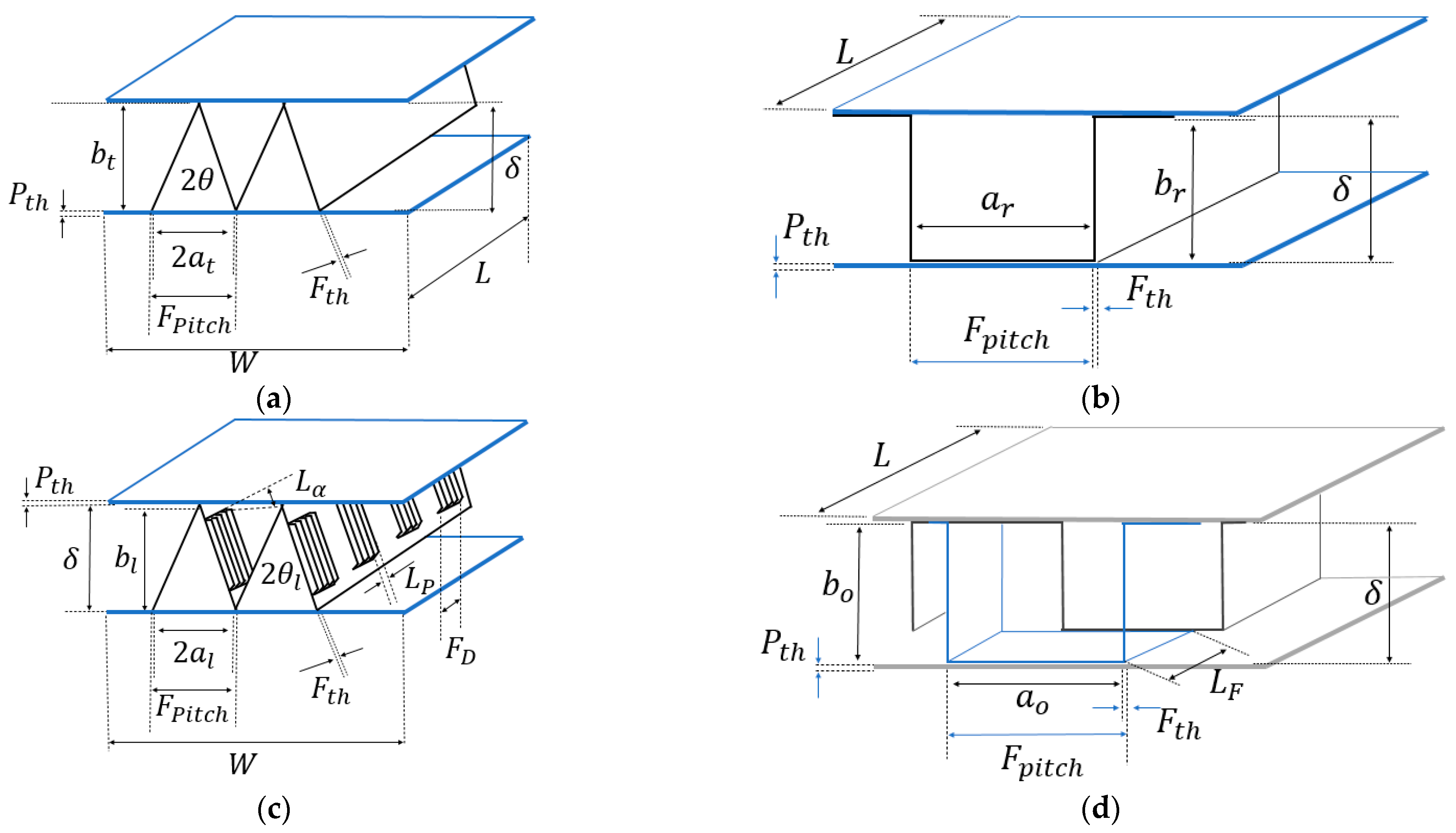
Figure 1. Geometry of finned surfaces: (a) triangular, (b) rectangular, (c) louvered, (d) offset strip-fin.
Energies 14 02318 g001
Figure 2. Block diagram of the overall finned surface design process.
Energies 14 02318 g002
Figure 3. Experimental vs correlation calculations for offset 1/8-15.2. (a) Colburn factor Equation (41), (b) friction factor Equation (45).
Energies 14 02318 g003
Figure 4. Pictorial representation of the volume design region: (a) maximum volume, (b) minimum volume.
Energies 14 02318 g004
Figure 5. Volume design region for the case study using offset strip-fins. (a) Maximum volume, (b) minimum volume, (c) volume design region.
Energies 14 02318 g005
Figure 6. Allowable heat exchanger width using different fin types.
Energies 14 02318 g006
Figure 7. Fin density for hot and cold streams vs. heat exchanger dimensions using offset surfaces: (a) height vs. fin density (b) length vs. fin density.
Energies 14 02318 g007
Table 1. Free flow area and hydraulic diameter for triangular, rectangular, offset, and louvred surfaces.
Surface Type Free   Flow   Area   A c   ( m 2 ) Hydraulic   Diameter   d h   ( m )
Triangular A c t = 2 ( F p i t c h t F t h t ) ( δ t F t h t ) (7) d h t = 8 ( F p i t c h t F t h t ) ( δ t F t h t ) ( 4 a t + F p i t c h F t h h   ) + 4 δ t C o s   θ t (8)
Rectangular A C R = ( δ R F t h R ) ( F p i t c h R F t h R ) (9) d h R = 2 ( F p i t c h R F t h R )   ( δ R F t h R ) ( F p i t c h R 2 F t h R ) + ( δ R F t h R ) (10)
Offset A C o = ( δ o F t h o ) ( F p i t c h o F t h o ) (11) d h o = 2 ( F p i t c h o F t h o )   ( δ o F t h o ) ( F p i t c h o 2 F t h o ) + ( δ o F t h o ) (12)
Louvered A c l = 2 ( F p i t c h l F t h l ) ( δ l F t h l ) (13) d h l = 8 ( a l b l ) ( 4 a l + F p i t c h l F t h l   ) + 4 δ l C o s   θ l (14)
Table 2. Ratio of secondary surface of total area and area density for triangular, rectangular, offset, and louvred surfaces.
Surface Type Ratio   of   Sec ondary   Area   to   Total   Area   f s   ( 1 ) Area   Density   β   ( m 2 m 3 )
Triangular f s = ( δ F t h ) / c o s θ [ ( a t F t h ) + ( δ F t h ) / c o s θ ] (15) β t = 4 ( F p i t c h t F t h t + δ t C o s   θ t ) / ( F p i t c h t   δ t ) (16)
Rectangular f s = [ ( F p i t c h F t h ) + 2 ( δ F t h ) ] [ 2 ( F p i t c h 2 F t h ) + 2 ( δ F t h ) ] (17) β R = [ 2 ( F p i t c h R F t h R ) + 2 ( δ R F t h R ) ] / ( F p i t c h R   δ R ) (18)
Offset f s = [ ( F p i t c h F t h ) + 2 ( δ F t h ) ] [ 2 ( F p i t c h 2 F t h ) + 2 ( δ F t h ) ] (19) β o = [ 2 ( F p i t c h o F t h o ) + 2 ( δ o F t h o ) ] / ( F p i t c h o   δ o ) (20)
Louvered f s = ( δ F t h ) / c o s θ [ ( a l F t h ) + ( δ F t h ) / c o s θ ] (21) β l = 4 ( a l + δ l C o s   θ l ) / ( F p i t c h l   δ l ) (22)
Table 3. Correlations for several heat transfer surfaces.
Expression Range of Validity Std Dev Notes
Rectangular surfaces
j = 0.233 R e 0.48 ( F p i t c h δ ) 0.192 [ F t h δ ] 0.208 (34) 2700 < R e < 10 , 000 ±5.3%[28]
f = 0.029 R e 0.09 ( F p i t c h δ ) 0.034 [ F t h δ ] 0.169 (35) 2700 < R e < 10 , 000 ±3.4%[28]
j = h A c m C p P r 2 / 3 (36)
Triangular surfaces
j = 0.718 R e 0.625 [ δ / F p i t c h ] 0.765 [ F t h / F p i t c h ] 0.765 (37) 100 < R e < 1000 ±12%[28]
j = 0.789 R e 1.1218 [ δ / F p i t c h ] 1.235 [ F t h / F p i t c h ] 0.764 (38) 1000 < R e < 10 , 000 ±12%[28]
f = 3.12 R e 0.852 [ δ / F p i t c h ] 0.156 [ F t h / F p i t c h ] 0.184 (39) 100 < R e < 1000 ±11%[28]
f = 2.69 R e 0.918 [ δ / F p i t c h ] 0.355 [ F t h / F p i t c h ] 0.175 (40) 1000 < R e < 10 , 000 ±11%[28]
Offset strip-fin surfaces
j = 0.6522 R e 0.5403 ξ 0.1541 δ 0.1499 η 0.0678 ( 1 + 5.269 × 10 5 R e 1.34 ξ 0.504 δ 0.456 η 1.055 ) 0.1 (41) 300 < R e < 3500 [9]
ξ = a o b o (42),
δ o f f = F t h L f o   (43)
η = F t h a o (44)
f = 9.6243 R e 0.7422 ξ 0.1856 δ 0.3053 η 0.2659 ( 1 + 1.7669 × 10 8 R e 4.429 ξ 0.92 δ 3.767 η 0.236 ) 0.1 (45) 300 < R e < 3500 [9]
d h = 4 a o b o L f o 2 ( a o L f o + b o L f o + F t h b o ) + F t h a o (46)
ln ( j ) = 0.0264136 ( l n R e ) 3 + 0.555843 ( l n R e ) 2 4.09241 l n R e + 6.21681 (47) 300 < R e < 3500 [9]
d h = 2 a o b o a o + b o (48)
ln ( f ) = 0.132856 ( l n R e ) 2 2.28042 l n R e + 6.79634 (49) 300 < R e < 3500 ξ = a o b o (50)
Louvered surfaces
j = R e [ 0.484 1.887 l n R e ] [ F d L p ] 0.157 [ 2.24 0.588 l n ( F p i t c h sin L α L p ) ] (51) 100 < R e < 3000 [29]
R e = m ˙ L p μ A c (52)
f = R e 0.433 [ F d L p ] 0.185 ( 1.10 + 4.31 ( L α 90 ) 2 + 0.836 ln ( F p i t c h L p ) ( F p i t c h L p ) 2 ) (53) 100 < R e < 3000 [29]
Table 4. Average deviation for Colburn and friction factor for strip fin surface 1/8-15.2.
R e (1) j e x p (1) f e x p (1) j M B (1) j A L (1) f M B (1) D e v J M B (1) D e v J A L (%) D e v f M B (%)
3000.01810.1390.030170.019380.1456−67%−7%−5%
4000.016750.11450.025950.017770.1178−55%−6%−3%
5000.01580.1010.023120.016770.1003−46%−6%1%
6000.01520.09130.021060.016070.0883−39%−6%3%
8000.014270.080.018210.015120.07358−28%−6%8%
10000.013730.07260.016310.014470.06546−19%−5%10%
12000.013270.06760.014920.013970.06051−12%−5%10%
15000.012670.06280.013410.013370.05577−6%−6%11%
20000.011770.05840.011730.012590.05080%−7%13%
25000.01110.05580.01060.011950.047445%−8%15%
30000.01040.0540.0097690.01140.044896%−10%17%
40000.009590.05160.008610.010470.0411710%−9%20%
50000.008960.04980.0078210.009690.0385113%−8%23%
60000.00850.04870.0072360.0090170.0364615%−6%25%
Table 5. Total average and standard deviation for Colburn and friction factor for strip-fin surfaces.
Standard Deviation (%)
Surfacej
Equation (43)
j
Equation (49)
f
Equation (47)
1/8-15.227%1%9%
1/8-19.82 (D)2%2%7%
1/8-13.955%13%5%
1/8-15.6120%5%13%
1/8-19.8618%4%2%
1/8-16.12 (T)18%11%14%
1/8-20.06 (D)16%4%4%
1/8-16.00 (D)16%4%4%
1/8-16.12 (D)17%9%5%
1/8-24.1214%2%14%
1/9-25.0114%3%4%
1/9-22.6826%26%3%
1/10-27.0317%2%2%
1/10-19.3516%3%8%
1/10-19.7416%6%10%
Avg std dev16%6%7%
Table 6. Operating data and physical properties for the case study.
Flow Stream ParametersCold StreamHot Stream
Mass flow rate (kg/s) 101.4030
Pressure drop (Pa) 10,00025,000
Inlet temperature (K) 303.15363.15
Outlet temperature (K) 313.15313.15
Density (kg/m3) 995.0750
Heat capacity (J/kg K) 42002840
Thermal conductivity (W/m K) 0.590.19
Viscosity (kg/m s) 0.000340.0008
Heat capacity mass flow rate CP (W/K)425,88085,200
Thermal conductivity material of construction (W/m K)16.30
Heat load (W)4,260,000
Plate spacing (m)0.0065
Fin thickness (m)0.0003
Plate thickness (m)0.002
Table 7. Volume and block dimensions for the case study
DimensionTriangularRectangularOffset Strip-FinLouvered
Fin (Fins/In)Fin (Fins/In)Fin (Fins/In)Fin (Fins/In)
Fin = 4Fin = 28.2Fin = 1Fin = 28.2Fin = 5Fin = 28.2Fin = 1Fin = 28.2
Volume (m3)1.960.0353.370.0121.020.091.680.045
Width (m)0.4050.680.600.650.550.580.680.66
Height (m)0.4050.680.600.650.550.580.680.66
Length (m)14.730.0910.170.033.590.284.250.28
Free flow area (m2)0.058
0.058
0.061
0.061
0.16
0.16
0.13
0.13
0.13
0.13
0.10
0.10
0.19
0.19
0.12
0.12
Reynolds number (1)2520
20,040
198
1580
5164
41,070
340.7
2710
4435
35,270
852.40
6780
1714
13,630
184.6
1470
Surface area (m2)778.3
778.3
62.63
62.63
283.2
283.2
131.7
131.7
234.2
234.2
96.35
96.35
340.50
340.50
89
89
Pressure drop (Pa)7791
10,000
8637
10,000
1161
10,000
1161
10,000
2160
10,000
2215
10,000
817.70
10,000
277.40
10,000
Table 8. Design results for a width of 0.75 m and height of 0.75 m.
DimensionTriangularRectangularOffset Strip-FinLouvered
Fin (Fins/In)Fin (Fins/In)Fin (Fins/In)Fin (Fins/in)
Hot SideCold SideHot SideCold SideHot SideCold SideHot SideCold Side
Fin = 10.7Fin = 20Fin = 8.4Fin = 20Fin = 7.6Fin = 20Fin = 17.6Fin = 20
Volume (m3)0.390.630.740.09
Width (m)0.750.750.750.75
Height (m)0.750.750.750.75
Length (m)0.851.201.420.18
Free flow area (m2)0.160.120.230.200.230.190.190.18
Reynolds number (1)381.7017881706567917065679226.41599
Surface area (m2)301512.60220.70484.50241.1576.6113.7128
Pressure drop (Pa)125710,000332.6010,000488.210,00088.5410,000
Publisher’s Note: MDPI stays neutral with regard to jurisdictional claims in published maps and institutional affiliations.