1. Introduction
A cyclone, also known as a cyclone separator, is a device for separating solid particles from gas, and uses for this purpose the centrifugal force acting on a particle produced by the swirling gas. The principle of gas purification in a cyclone, which consists in rotating an aerosol stream, has not changed since 1885, when it was patented in the USA [
1]. The cyclone patent was granted to John M. Finch from the United States in 1885 and transferred to the Knickerbocker company. Although the “dust collector,” as it was then called, contained the essence of modern cyclones, the dust could have emerged from the side of the cylindrical body rather than from the bottom of the conical portion as it does today. It was also quite a complex device and did not resemble today′s cyclones [
1].
Due to the simple, solid structure, lack of moving parts, high operational safety and due to stable and low pressure drops, as well as the comparatively low investment and operating costs, cyclones are very efficient and popular devices for separating solids from the air stream, not only in industry, but also for filtering the intake air in vehicle internal combustion engines, agricultural and construction machinery. A cyclone works by making the gas stream rotate and the particles acquire centrifugal force. Gas stream rotation can be achieved by tangentially bringing it to the top of the cylindrical part or by flowing through a stationary swirler (located at the inlet of the cylindrical part), made of profiled blades with a helical outline, where the rectilinear movement changes into a swirling motion, which then changes into a helical movement.
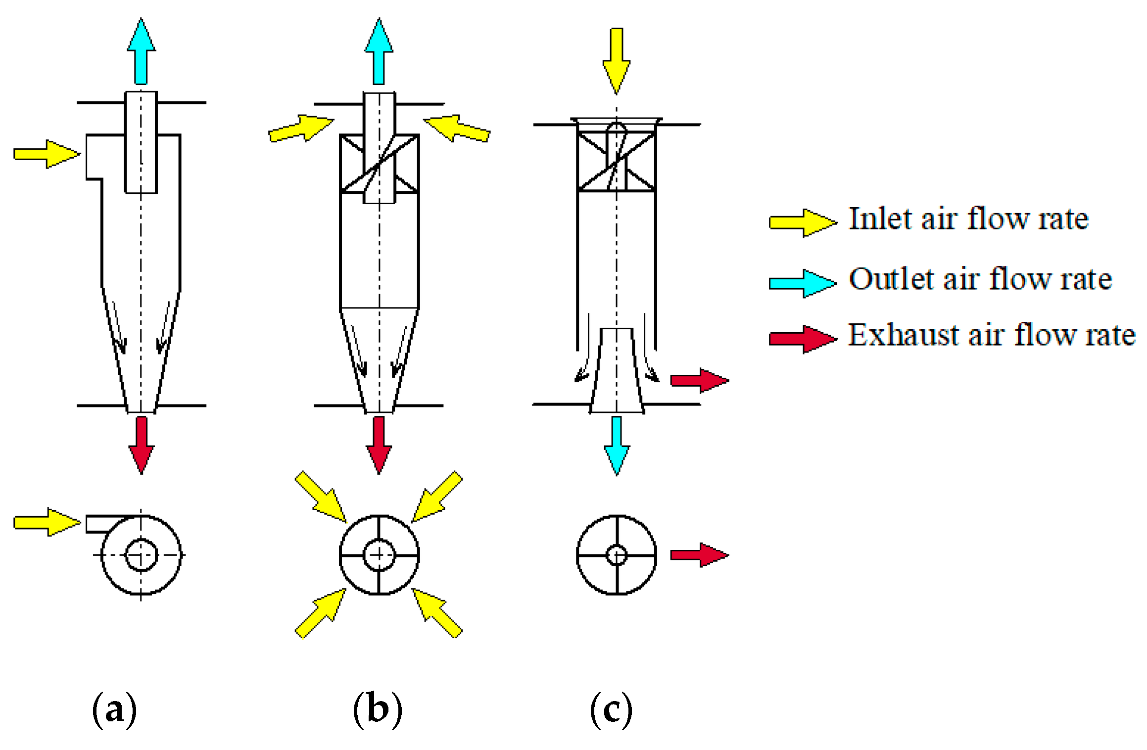
Due to operation principle, cyclones are divided into reverse, when the flowing aerosol stream changes flow direction by 180° (
Figure 1a,b); clean gas and collected particles leave the device on opposite sides and axial flow, when the flowing aerosol stream does not change flow direction, then the gas and particles “pass” through the cyclone in only one direction, leaving the device from the same end (
Figure 1c).
In a reverse cyclone, the gas stream, after reaching the bottom of the cone, turns into a backward helical movement upwards and flows out through an outlet pipe made centrally in relation to the cylindrical part of the cyclone or in the center of the swirler, and then continues to move in a helical motion. In an axial-flow cyclone, the gas stream does not change direction and exits through a centrally located outlet tube where it continues to rotate in a helical motion.
Theoretical and experimental cyclone studies, the design of which has not changed much over the years, have been carried out since the 19th century, and therefore the available literature contains many studies presenting numerical and experimental studies with results of the process of aerosol separation in return cyclones with tangential inlet, e.g., [
2,
3,
4,
5,
6,
7]. Tests of a return cyclone with a tangential inlet carried out so far have focused on its four basic elements: the cyclone inlet [
8,
9,
10,
11,
12,
13,
14], the cyclone body [
15,
16], the cyclone outlet pipe [
17,
18], the outlet and the dust container [
19,
20].
Compared to other purifying devices, cyclones have many advantages, for example [
21,
22,
23,
24]:
simple and compact structure, no moving rotating parts and frictionally cooperating elements, which ensures high reliability;
low operating costs: they do not require maintenance because they do not use surface filters that require regeneration;
ability to work in difficult conditions, such as: high temperature and pressure, different gas humidity;
relatively low and constant (not increasing for the same air stream flowing to the engine) pressure drop during operation, which ensures low energy consumption; pressure drop increases only in partition filters, where as a result of the retention and dust accumulation, the structure of the filter bed is densified, and thus the air flow is hindered;
high throughput: the ability to separate large dust mass from large air streams;
constant characteristics during operation, depending only on the air stream, the value of which changes insignificantly depending on the engine speed.
Cyclones also have some disadvantages, for example:
separation efficiency decrease in the absence of tightness;
pressure drop increase with increasing flow velocity, which increases energy consumption;
low separation efficiency of polluted air from particles dp <10 µm.
Return cyclone with tangential inlet, due to its significant advantages, is widely used in filtration processes in many industries. Large cyclones with a body diameter of up to several meters are used in sawmills [
25], cement mills [
26], oil refineries [
27], coking plants, metallurgy, building materials plants and grain processing.
Cyclones are used to filter waste gases in many processes related to energy and heat production, both on a large scale, where energy generation technologies are based on burning coal [
28], and where energy is produced on a smaller scale, e.g., heat recovered during the incineration of municipal waste. Smaller diameter cyclones are used for bioaerosol sampling, drug-delivery systems and also for vacuum cleaners. Cyclones with internal diameters of 40 mm and smaller ones are used in air intake filtration systems for combustion engines in tracked vehicles, working and agricultural machines, operated most often in conditions of high dust concentration in the air, the value of which often exceeds 1 g/m
3 [
29,
30,
31,
32].
Axial flow cyclones are characterized by several times lower pressure drop than reverse cyclones and, unfortunately, a slightly lower separation efficiency, but more favorable installation conditions in the engine intake system. The air stream then flows through the filter without turbulence, without changing its direction, which results in less energy loss of the motor [
33]. Thus, axial flow cyclones are attracting increasing attention and are becoming future-oriented devices for filtering intake air in internal combustion engines [
34].
Motor vehicle engines suck in from the environment pollution of maximum sizes up to 80–100 µm and different chemical composition, which characterizes greater mass of SiO2 and Al2O3 67–91% and 5–14%, respectively, and with smaller mass share of other ingredients: Fe2O3, MgO, CaO. Particles in the inlet gas stream vary so much in size, density, shape, viscosity, brittleness, erosion, surface charge, concentration, and other characteristics that no separation method or type of separator is suitable for capturing the entire spectrum.
Dust suspended in the air is the most common cause of accelerated wear of two frictionally cooperating machine elements, such as the P-PR-C coupling elements (piston-piston rings-cylinder walls) in engines. The dust sucked in with the air enters the combustion chamber (above the piston) and, therefore, the upper part of the cylinder and piston as well as the upper piston rings are subject to the greatest wear. Abrasive wear of engine components is caused mainly by particles of 1–40 µm, with the most harmful particles in the range of 1–20 µm [
35,
36,
37]. About 30% of the pollutants entering the engine escape unchanged along with the exhaust gases from the cylinders to the exhaust system. Only 10–20% of the dust that enters into the engine with the air through the intake system settles on the cylinder liner wall. Together with the oil, this part of the dust forms a kind of abrasive paste which, in contact with the mating surfaces of the engine, for example P-PR-C, causes abrasive wear. The most dangerous for two cooperating engine components are dust particles whose diameter
dp is equal to the oil film thickness
hmin between this two surfaces at the moment. In typical combinations of internal combustion engine, oil thickness film depends on the conditions and parameters of the engine as well as the properties of the oil and, therefore, they assume different values in the range of
hmin = 0–10 µm [
38]. Moreover, the value of the minimum oil film thickness and the period of its occurrence in the engine cycle depends on sliding surfaces’ shape asymmetry geometry.
Excessive wear of the P-P-C connection is the cause of increased blowing of fresh load into the crankcase, which causes a decrease in compression pressure and engine power, an increase in exhaust gas blow-by into the crankcase, which accelerates oil aging and increased consumption of oil flowing over the piston, which increases solid particles emissions [
39,
40]. One of the ways to reduce the friction and wear of the P-P-C connection is to use surface asymmetry shape of the slip rings while maintaining the required thickness of the oil film necessary for the fluid friction conditions between the mating surfaces [
41]. Another way to reduce friction between engine components reciprocating or rotating, increasing fuel economy along with emission and noise requirements, is to use a modern Common Rail fuel injection system capable of injection pressures above 2500 bars in combination with a newly developed combustion system [
42,
43].
Thus, a gas filtration device must be able to retain a wide variety of materials ranging from tens of micrometer particles to sub-micrometer particles, from hard minerals such as silica (SiO2) to soft food products. Some of these materials are very free flowing, while others tend to coagulate. For this reason and due to high dust concentrations occurring during the operation of off-road and special vehicles, two-stage systems of engine intake air filtration are used: inertial filter and partition filter connected in series. The first stage of filtration is usually a multicyclone, where initial filtration takes place-separation of the largest particles of impurities (over 15–35 µm) and mass. Small-sized dust grains remaining in the air stream are directed to a partition filter, usually made of pleated paper with a suitable surface, where they are retained with an accuracy of more than dp = 2–5 µm.
As a result, required air purity is supplied to the engine cylinders, which reduces piston rings and cylinder surfaces wear, thus increasing engine and vehicle reliability. At the same time, the filtration system’s operation time is extended, limited by the filter cartridge reaching a certain value of the permissible resistance Δpfdop.
In modern trucks, working machines, farm tractors and helicopters, axial flow cyclone assemblies are already widely used as the first stage filtration instead of return cyclones with a tangential inlet [
44]. A porous partition (filter cartridge) made of pleated filter paper placed in series behind the multicyclone is characterized by high separation efficiency (over 99.5%) of dust grains over 5 µm, limited and low (220–250 g/m
2) dust absorption, and continuous increase in pressure drop due to the retention and dust accumulation inside a thin layer of paper (0.6–0.8 mm). Air filter pressure drop, which increases during operation (resulting from an increase in the filter element resistance), causes additional energy losses in the engine and, therefore, should not exceed the permissible value Δ
pfdop. set by the standards. The value of Δ
pfdop. is determined from the condition of a 3% decrease in engine power and is 2.5–4.0 kPa-passenger car engines, 4–7 kPa-truck engines and 9–12 kPa-special purpose vehicles [
45]. After reaching the permissible value of Δ
pfdop, the filter element, although it still maintains a high separation efficiency, should be replaced with a new one, so that it does not cause an additional increase in filter resistance and engine energy losses in the form of power decrease and an increase in specific fuel consumption. From a technical point of view, air filter service life is commonly defined as the restriction level that causes the pressure on the passenger car filter to drop by about 2.5 kPa above pressure drop of the new (clean) filter [
46]. For trucks and special vehicles, the Δ
pfdop. values are assumed to be approximately 6.25–7.5 kPa above the pressure drop of clean air filter [
47].
Depending on dust mass directed with air onto the filter cartridge, which in a two-stage filter is mainly determined by cyclone separation efficiency, increase in air pressure drop occurs with varying intensity. A group of cyclones (multicyclones), which is the first stage of filtration, retains a significant (87–95%) dust mass, which means that only a small part of it goes to the second stage of filtration.
Thus, the increase in the pressure drop of the filter element is less intense, which increases the service life of the air filter several times, and thus the vehicle life without the need to service the filter. Each increase in cyclone filtration efficiency means a smaller dust mass directed to the second filtration stage, which translates into a less intensive increase in filter resistance, lower energy consumption by the engine and an extension of the time until permissible value of Δpfdop is reached. Therefore, it is justified to conduct works aimed at testing axial-flow cyclones in terms of improving the efficiency and filtration accuracy while maintaining a low pressure drop.
However, it is not very common to find papers presenting the results of numerical studies and experimental cyclones. This can be explained by the difficulty of modeling and practical implementation with high precision of the swirler blades, which is the most technologically complicated part of the cyclone.
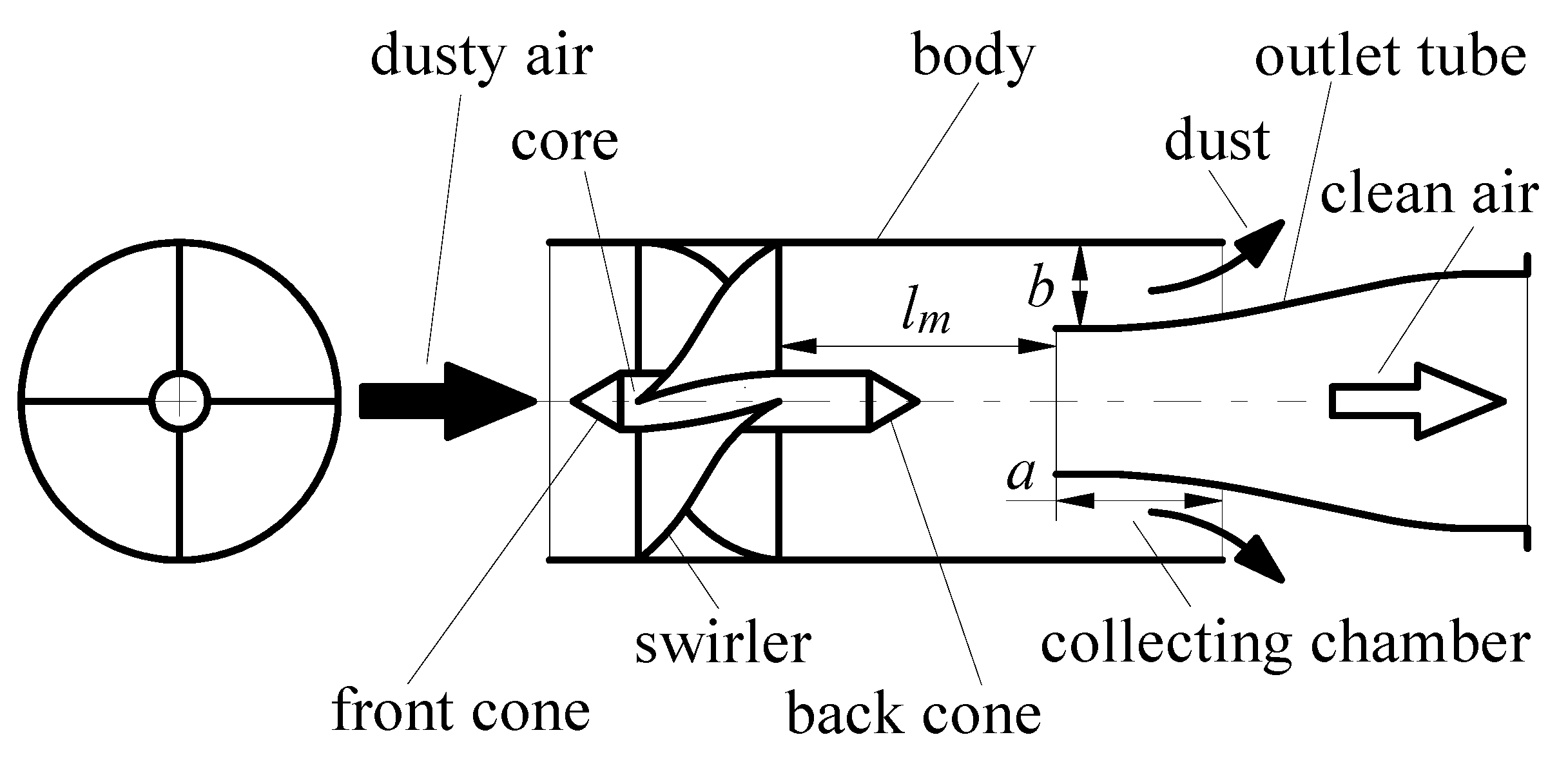
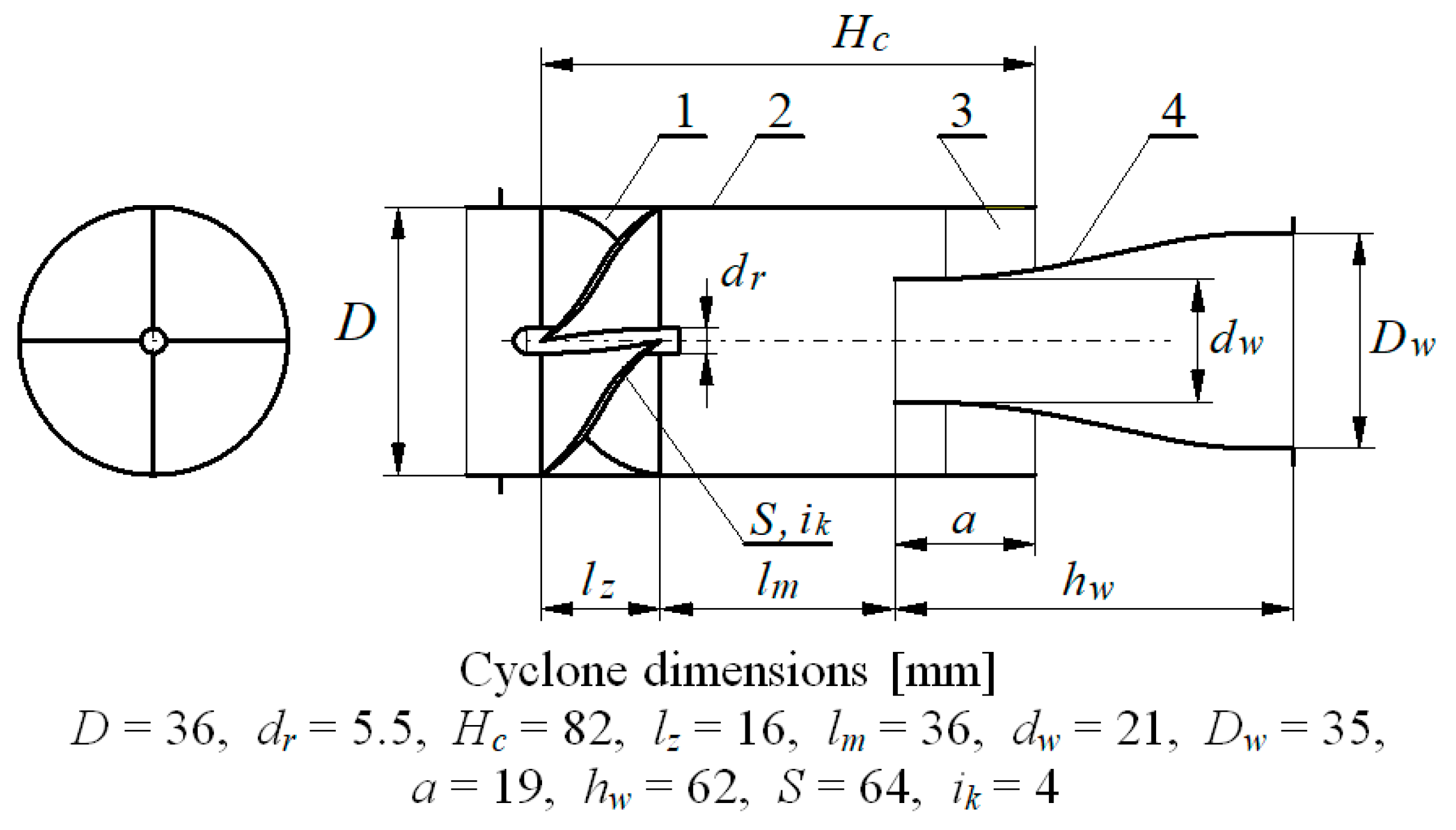
The axial-flow cyclone consists of three basic elements: a swirler, a cylindrical body and an outlet tube. The swirler, most often having four blades with a helical surface, is located in the front part of the cylindrical body (
Figure 2). Symmetrically arranged blades are inclined in relation to the cyclone axis (direction of air flow) at the angle
αk. The outer diameter of the swirler results from the inner diameter of the cylindrical body of the cyclone. The helical configuration of the blades presents serious manufacturing difficulties, especially for very small diameter turbulators. That is why handlebars with flat surfaces are often used.
In the central part of the swirler there is a cylindrical core, which is integral with the blades. Most often, the core extends beyond the rim of the blades (extension part) into the cyclone. In the case of a core with a diameter greater than 5 mm, a streamlined shape in the form of a hemisphere or a cone is attached at the inlet. A similar cone is mounted to the core on the outlet side of the swirler.
The cones are an integral part of the turbulators and can significantly affect cyclone pressure drop and efficiency. The main function of the front cone is to direct the incoming stream away from the central swirl area. The front cone directs the incoming air uniformly radially outward around the swirler. This direction of the air causes, by impinging on the front cone, an initial radial momentum to the dust particles towards the wall of the cylindrical portion.
A conical outlet tube is placed concentrically to the cylindrical part of the cyclone at a predetermined distance
lm from the cyclone, the circular cross-sectional area of which increases its value starting from the inlet opening towards the outlet. The outer wall of the conical outlet tube and the inner wall of the cylindrical body overlap and form a ring with a width of
b, called the dust collection chamber (
Figure 2).
Pressure drop generated by the cyclone and the separation efficiency are the key parameters characterizing the performance of the cyclone separator. The filtration characteristics of axial-flow cyclones depend on many variables that can be divided into three groups. The first group consists of geometric parameters that are characteristic dimensions of the cyclone elements. These are the dimensions:
- (a)
related to the cylindrical part of the cyclone: inner diameter of the cylindrical part D, height of the cylindrical part, separation length of the cyclone lm, length of the circumferential gap a;
- (b)
swirler: swirler length lz, steering wheel travel (helix pitch) S, number of vanes, diameter of swirl core dr;
- (c)
separation chamber: width of the collecting chamber b, length of the collecting chamber a;
- (d)
outlet tube: outlet tube length c, outlet tube inlet inner diameter dw, outlet tube outlet inner diameter Dw.
The parameters of the flowing aerosol are the second group in which the properties of the treated gas are distinguished: temperature, density, viscosity, dust concentration in the air and dust properties: density, particle size distribution, chemical composition, grain shape, tendency to coagulate. The third group is the gas flow conditions in the cyclone, including: gas flow velocity through the cyclone, degree of suction, type of gas flowing.
Due to the fact that separation efficiency and pressure drop in a cyclone, including axial flow cyclones, are determined by a large number of parameters, this prompted scientists to use Computational Fluid Dynamics (CFD) programs to evaluate them, partially eliminating the need for time-consuming and costly experimental research, and shortens design work.
Computer simulation packages, based on specially created codes (CFD) [
48] are helpful tools that are successfully used during the design and optimization of devices operation used in energy production [
49,
50,
51], chemical engineering [
52,
53], process engineering [
54,
55] and environmental protection processes [
56]. The versatility of application, the possibility of quick modification of the size and geometry of the designed device, as well as the wide possibilities of simulating single and multiphase flows, make them useful for the analysis and design optimization of axial-flow cyclones.
However, in the available literature, there are not too many numerical test results showing the influence of cyclone and flowing aerosol parameters on the performance of the axial-flow cyclone. The subject of the research were the individual elements of the cyclone: the number of swirl guides, the angle of the steering wheel [
57,
58,
59,
60,
61,
62,
63], the pitch of the swirler′s spiral, the height and diameter of the swirler and the diameter of the core [
57,
61,
64], the width of the collecting chamber gap [
57,
61,
65], distance of the swirler from the inlet of the outlet pipe [
57,
64], diameter and height of the cylindrical part of the cyclone [
64].
For example, Klujszo et al. [
57] carried out a numerical study of the influence of different designs of the swirl blades, the diameter of the swirler and the diameter of the core, the width of the collecting chamber gap and the distance of the swirler from the outlet pipe inlet on the efficiency and flow resistance of axial-flow cyclone. Using the CFD model, three different constructions of the swirl flaps were simulated: straight, 3-plane (20°, 20°, 20°) and 3-plane (30°, 20°, 10°) vanes. In all cases, the total angle of the steering wheels was kept at 60°. Compared to straight blades, three-plane blades, which gradually change the flow, significantly reduce the pressure drop of the cyclone. It has been found that the distance of the swirler from the inlet of the outlet tube (separation distance 1 m) has a slight influence on the pressure drop and the separation efficiency. It has been shown that for a fixed diameter of the swirler, an increase in the diameter of the core and the cone face reduces the flow area between the guides, causing an increase in the flow velocity and an increase in the pressure drop.
The gap width of the collecting chamber b has a significant influence on the efficiency and flow resistance of the cyclone. Increasing the b-size reduces the inlet diameter of the outlet tube dw, increasing the flow velocity of the stream and increasing the pressure drop while increasing the separation efficiency due to the larger dust mass being trapped by the larger aperture. At the same time, the width of the slit b should be as small as possible in order to reduce the pressure loss as it flows through the outlet pipe.
However, when the width b is reduced too much, dust is deposited on its walls, which deteriorates its permeability, as a result of which the separation efficiency deteriorates. Therefore, the dimensions of the slot should be selected depending on the diameter of the swirler. for a swirler with a diameter of 50.8 mm, a gap of about 6.4 mm turned out to be the best solution.
The authors of [
65] came to similar conclusions by examining the effect of the gap width of the collecting chamber in the range
b = 1.5–7.5 mm on the cyclone performance. They determined that the chamber width for the swirler diameter
D = 45 mm and the steering wheel travel (helix pitch)
S = 85.7 mm cannot be less than 6.5 mm.
Gopalakrishnan et al. [
58] investigated the efficiency and pressure drop of the axial-flow cyclone with an axial inlet depending on the number of swirl flaps (3, 4 and 5), its height and the steering angle. Each of these parameters was variable while keeping other factors constant. It has been observed that with a larger number of blades, the pressure drop increases with no increase in the separation efficiency. By increasing the tilt angle of the steering wheel in the range of 145–175°, the simultaneous increase in separation efficiency and pressure drop was achieved. It has been found that the height of the swirler is a sensitive parameter and has a significant effect on both the pressure drop and the separation efficiency. The flow resistance decreases with the height of the swirler, but at the cost of a decrease in separation efficiency.
In [
59], the CFD method was used to investigate the effect of the number (6, 8 and 10) of guide vanes on the pressure drop of axial-flow cyclones. It was found that with an increase in the number of blades, the pressure drop of the axial-flow cyclones at the same inlet velocity becomes smaller and smaller.
The experimental research presented in [
64] was aimed at determining the interaction of the cyclone diameter
D, the active length of the cyclone
lm, and turbulators with different blade pitch on the performance of the axial-flow cyclone. It has been shown that regardless of the diameter of the cyclone
D, there is a clear maximum of separation efficiency, depending on
lm, which moves towards higher values of
lm with the increase of the swirl guide pitch. It was found that the optimal diameter of the cyclone and the optimal active length should be 45.6 mm and 80 mm, respectively, at the steering wheel stroke S = 72.5 mm.
Mao et al. [
60] presented a study of the influence of three parameters of axial-flow cyclone: the shape of the steering wheel, the angle of the blades′ outlet and the diameter of the guide cone on separation efficiency and pressure drop. The shapes of the steering wheels are divided into five types. The flap angles had the following values: 20°, 25°, 30°, 35°, 40°. The diameter of the guide cone includes five sizes: 0.3
D, 0.4
D, 0.5
D, 0.6
D and 0.7
D, where
D = 50 mm–the diameter of the swirler.
The shape of the guide bar and the angle of the guide bar can affect the separation efficiency and pressure drop of the cyclone. The diameter of the guide cone affects the pressure drop of the cyclone, but does not affect its separation efficiency.
During numerical tests, the authors of [
61] found that reducing the angle of deflection of the vanes α may increase the tangential velocity and improve the separation efficiency, but it is associated with an increase in the pressure drop. On the other hand, increasing the turning angle
β of the blades causes an intensive increase in the pressure drop and a slight increase in the separation efficiency. In turn, increasing the core diameter
Dc leads to an increase in the tangential and axial velocity in the cyclone, and also significantly increases the pressure drop. To obtain high separation efficiency, the diameter
Dc should be 65–70 mm.
As a result of research, many cyclone designs have been developed for specific applications. Reference [
66] optimized the shape of an axial flow cyclone for air purification in an underground station using the fluid dynamics (CFD) method. The 50% 2.5 µM solids separation efficiency was achieved with minimal pressure drop. On the other hand, the authors of [
67] developed an axial flow cyclone for the separation of nanoparticles with a diameter of 272–448 nm. Hsu et al. found that an axial flow cyclone can collect ultrafine particles [
68]. The authors of the work [
69], as a result of the multifunctional optimization of the cyclone structure with axial flow, achieved a compromise between the static pressure drop and the separation efficiency. The 8 µm particle removal efficiency increased by 100% and the static pressure drop increased by 69.3%.
The analysis shows that the numerical tests of the axial-flow cyclone focus mainly on the assessment of the influence of the swirler′s parameters on the efficiency and resistance of the cyclone flow. The subject of the tests are: the height of the swirler and its diameter, the diameter of the core, various constructions of the swirler blades, the number of blades, and the angle of the steering wheel. There are no studies on the inlet diameter of the outlet tube, and little work has been done on the effect of the distance of the swirler from the outlet tube inlet on the cyclone performance.
The results of numerical tests obtained from many models are not experimentally verified with the use of real dust, which calls into question the reliability of the model. Therefore, in order to partially fill the gap in this respect, the authors developed a model of a axial-flow cyclone and performed its research on the impact of the separation length of the cyclone, the internal diameter of the outlet pipe and the length of the swirl core on the efficiency and pressure drop. Using the results of similar studies and the results of their own numerical research, they validated the constructed model, and then printed the cyclone prototype using the additive manufacturing technique. The cyclone obtained in this way was tested experimentally in terms of separation efficiency and pressure drop with the use of test dust for various inlet velocities. The measures taken aimed at improving the efficiency and filtration accuracy while maintaining a low pressure drop of the cyclone.
2. Theoretical Basis of Aerosol Filtration in Cyclones
The aerosol separation process in a cyclone, although its structure is not complicated, is very complex and difficult to describe mathematically, therefore little has been published on their design and calculation. This is mainly due to the complex motion of the gas, which is not only a rotational (helical) motion, but also a two-way reverse motion, and a number of side effects occurring at that time. For this reason, there is no precise mathematical description of dust grains’ movement in the cyclone, which is relative both to the fixed walls of the device and to the gas flowing inside the cyclone. This movement takes place in a space-varying (and specific for each cyclone structure) field of gas velocity, and thus is under the influence of the system of forces acting on each grain changing in space. Additional difficulties are different grain sizes, their density and shape, and resulting various force relationships (inertia and aerodynamic), as well as the possibility of grain collisions with the cyclone walls and causing, among others, dust coagulation. Models of particle movement in cyclones, found in many studies, were developed using the main dimensions of the cyclone, parameters of the flowing aerosol and with many simplifying assumptions, such as [
22,
70,
71,
72,
73]:
dust particle moves in a laminar motion within the validity range of Stokes’ law;
dust particles are homogeneous spheres;
coagulation of dust grains is not taken into account and there is no detachment from the cyclone walls;
gas moves in the cyclone along a specific, adopted spiral equation;
cyclone body is a cylinder with a constant diameter along its entire length.
In the cyclone, as a result of the supply and swirl of the air stream, the dust grains inside it, the density of which is more than 2500 times greater than the air density, remain, under the influence of the inertia force FB and overcoming the resistance force of the FR medium, directed to the inner wall of the cyclone, after reaching it, they slow down and stop, and then, as a result of gravity, they fall into the dust collector located below. An increase in the air flow velocity to the cyclone, and thus the increase in the velocity of dust particles, increases the inertia force, which increases cyclone separation efficiency.
The obtained radial velocity of the dust grains causes their collision with the cyclone wall [
73,
74,
75]. The energy that the dust grains have at the moment of collision with the wall of the cyclone j may be significant, and then the grains will bounce and are carried away by the gas stream rapidly moving towards the cyclone outlet tube. Increasing the inlet velocity of the cyclone increases the energy of the grains, which may result in a greater intensity of their reflection. As a result, grains reflected from the walls of the cyclone will be more susceptible to being entrained by the outlet stream, which will reduce the separation efficiency.
A characteristic parameter of the cyclone′s operation is the inlet speed υ
0, which is defined as the quotient of the air stream flowing into the cyclone
Q0 and the cross-sectional area of the inlet stub pipe at its narrowest point
A0 and calculated from:
where:
Q0—aerosol air stream flowing into the cyclone,
A0–cross-sectional area of the inlet stub pipe at its narrowest point.
The contaminated air is supplied to the axial-flow cyclone along the cyclone axis, directly onto the vanes that form the swirler. Upon contact with the surface of the blades, which are inclined to the direction of the incoming air at an angle γ, path of dust grains changes. During the grain movement on the surface of the swirler′s blades, a peripheral velocity component appears. Due to its aerodynamic effect on dust grains, apart from the axial movement, they also perform a transverse movement, which causes grains to move to the channel wall. In this way, inhomogeneous dust concentration is created in the air stream along the radius of the cyclone, higher near the channel wall.
After lowering blades of the swirler, the dust grains’ path is helicoidal. These dust grains are influenced by: centrifugal force
FB, aerodynamic force
FR and buoyancy force
FG. In the plane perpendicular to the cyclone axis, two forces influence on dust grain: the inertia force
FB and the aerodynamic drag force of the
FR medium [
73,
76,
77]. Dust particles move in a helical motion, and the shape of this path will depend on the mutual relationship of two forces values
FB and
FR. The force of gravity has a negligible effect on the grain path and, therefore, is not taken into account in its motion. In turn, value of the
FB and
FR forces will depend on the diameter, shape and density of dust grain and the type of gas. The rotating aerosol causes the formation of a centrifugal force, the value of which for a dust grain of mass
mz located at a distance
r from the axis of rotation can be determined from [
77]:
where:
ρp–particle density,
dp–particle diameter,
us–tangential component of the particle velocity, equal approximately to the tangent gas velocity component
υS.
The centrifugal force causes a particle to move towards the cyclone wall at radial velocity
ur against drag force of the medium
FR. Resistance force of
FR center can be determined by [
77,
78]:
where:
Ap—projection surface of the particle (the projected surface area of the particle onto the plane perpendicular to the direction of its motion),
ρg—gas density,
λ—coefficient of frictional resistance,
ur—component of radial motion of the particle [
78].
where: Ψ
k—grain shape coefficient,
Re—Reynolds number.
Dust grains movement towards the cyclone wall is determined by the equation resulting from the mutual relationship of the centrifugal force and the resistance force of the medium [
72]:
The above equation shows that dust grains with diameters greater than a certain limiting dimension dzg, for which the FB > FR condition is met, will move in a helical motion, making larger and larger circles and approaching the wall of the cylindrical part of the cyclone. After reaching the cyclone wall, dust grains slow down and stop, and then fall by gravity into the settling tank, so they will be separated with 100% efficiency. On the other hand, dust particles with diameters greater than dzg, for which the resistance force FR is greater than the inertia force FB, will be directed to the center of the cyclone and will be entrained by the internal vortex of air flowing out of the cyclone outlet tube. For these particles, the separation efficiency is assumed to be 0%.
Dust grains with a dimension equal to
dzg, which are in the cyclone and for which the centrifugal force
FB and the radial drag component of the
FR medium are equal, will (theoretically) circulate in a circle with a radius
r. However, due to the very irregular shape of dust grains, which determines the value of the aerodynamic force and their different density, which affects grain mass and the centrifugal force, grains for which the
FB =
FR condition applies, do not circulate around a circle with a certain radius. It is assumed in the literature that 50% of them are retained in the cyclone and 50% are entrained by the internal vortex towards the cyclone outlet. The size of dust grains, the efficiency of which is 50%, is called the cut-off diameter
dzg and is marked as
d50 [
44,
72]
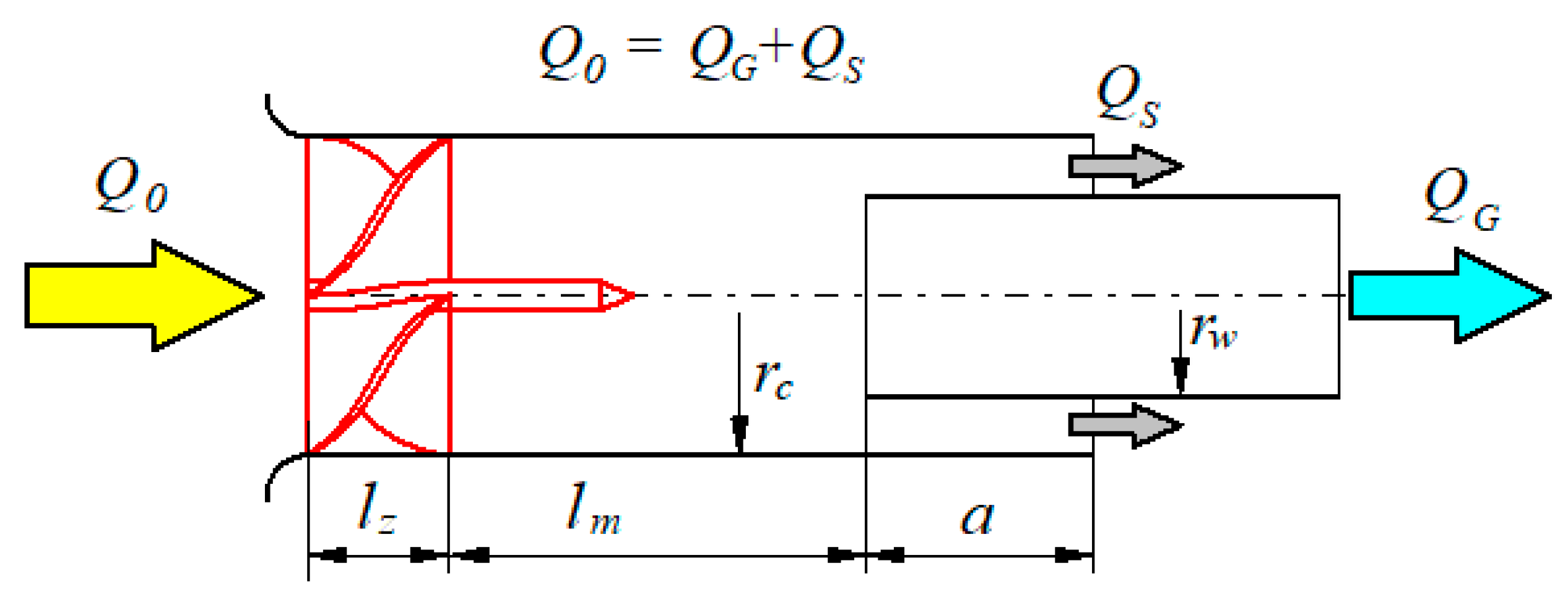
Authors [
35,
79] describe the boundary grain diameter
dzg in a axial flow cyclone (
Figure 3) with:
where:
Q0—air stream flowing through the cyclone,
rw—radius of the cyclone outlet tube,
lm—separation length of the cyclone,
S—steering wheel travel (helix pitch).
Above expression allows for determination of cyclone separation efficiency depending on the boundary grain diameter, as presented in [
35,
79]:
Authors [
80] derived analytically the dependence cyclone separation efficiency, which were used for filtering the intake air of helicopter engines in the following form:
where:
β—parameter determining the distribution of the air stream in the cyclone, defined by (
Figure 3):
where: QG—air stream sucked in by the engine, QS—air stream in the suction channel.
Taking the Stokes number for the helical flow in cyclones into account, the cyclone separation efficiency can be presented as follows [
80]:
According to the authors of [
80], Stokes number in cyclones can be determined by:
where:
ug—fluid velocity,
µg—fluid viscosity,
dp—particle diameter,
ρg—fluid density.
3. Axial Flow Cyclone Model
Analysis of aerosol flow through axial flow cyclone can be performed using the commercial engineering software Ansys Fluent. Using the equations of fluid mechanics, it is possible to determine the velocity distributions occurring inside the cyclone and to determine the trajectory of dust grains that are in the stream of flowing gas.
However, it is important to select an appropriate model that is suitable and will enable the solution of complex gas motion, which is not only a whirling (helical) motion, but a two-way reverse motion, with many side effects.
Authors [
81] proved that only the turbulent flow model of the RSM reflects the experimental test well.
The work uses the discrete phase model, which is characterized by the fact that the trajectory of particles is determined using Lagrange′s formulations. For the direction of flow “
x”, the balance of forces acting on the particle can be represented by the equation [
76]:
where:
FD(
u−
up)—drag force acting on the particle determined from:
where:
u—gas flow rate in the cyclone,
up—dust grains velocity,
µ—air dynamic viscosity,
—air density,
ρp—dust grains density,
dp—dust grain diameter,
Re—relative Reynolds number, which is defined is as:
Drag coefficient
occurring in the dependence (13) depends on the shapes of dust grains and the Reynolds number [
82]. There are many empirical dependencies in the available literature for determining the
CD resistance coefficients. However, the most popular is the relationship given by Morsi and Alexander, which determines the drag coefficient of a spherical particle moving in the air with the following relationship [
83], and the expression is important for a wide range of Reynolds number (
Re = 0.1÷50,000):
where:
a1,
a2,
a3—constants for spherical and smooth particles; the values of the constants
a1,
a2,
a3 for different ranges of the Reynolds number are given in [
78].
The following assumptions were made for model construction:
- (a)
Solid phase flow was defined as being a set of spherical particles (spheres) suspended in a continuous phase.
- (b)
The trajectory of particle motion is determined using Lagrange′s equations.
- (c)
The velocity and region of particle flow into the cyclone were defined.
- (d)
The grain size range and the particle size distribution of test dust were assumed.
- (e)
A homogeneous material of dust grains with a specific density corresponding to that of SiO2 was adopted.
- (f)
A defined velocity profile was defined at the cyclone inlet and atmospheric pressure was assumed at the outlet.
- (g)
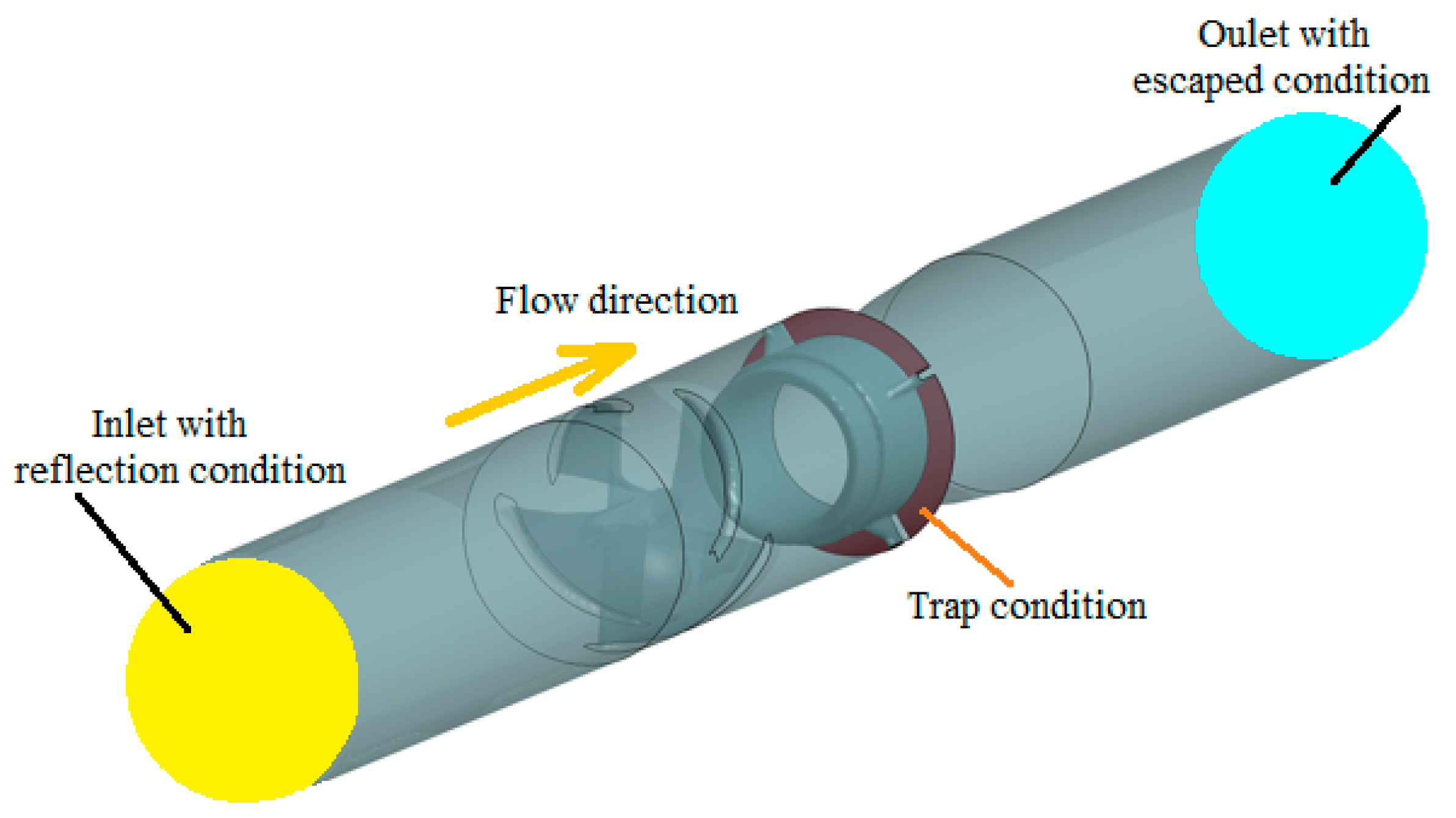
According to [
76,
84], the particle separation regions have been defined:
“reflect” condition—surfaces of swirler blades and internal walls of the cylindrical cyclone channel, where the particles are reflected;
“trap” condition—the surface of the cyclone outlet, where the number of dust grains retained by the cyclone is determined;
“escape” condition—an area where the number of dust grains that have not been stopped by the cyclone is defined.
For the “reflect” condition, the coefficient of restitution in the normal direction is determined by the relationship:
where:
en—restitution coefficient in the normal direction,
V1,n,
V2,n,—particle velocity in the direction normal to the wall before and after the collision.
Taking into account the above assumptions, the following relationship was adopted to calculate separation efficiency of axial flow cyclone:
where:
np,trapped—number of dust grains retained in cyclone,
np,injected—number of dust grains injected into the cyclone with air,
np,incomplete—number of uncounted dust grains.
For numerical and experimental tests in this work, the PTC-D test dust was used, which is a substitute for AC fine in Poland [
84]. The chemical and particle size composition of this dust is presented in
Table 1 and
Table 2. Basic dust components are SiO
2 and Al
2O
3, whose total share in the dust is less than 90%. They are also two hardest minerals, the hardness of which on the ten-point Mohs scale is 7 and 9, respectively. Moreover, the mass fraction of dust grains in the range of 0–5 µm is less than 40% of total dust mass. These are grains that are not retained in cyclones, but in partition filters made of filter paper with nanofibers addition.
During numerical tests, the particle size distribution of the PTC-D test dust was taken into account by using the Rosin-Rammler model, for which two parameters are determined:
n–spread parameter and
p–average dust grain diameter. A characteristic feature of this model is that size ranges of the diameters into which the dust taken for testing is to be divided are defined. Mass distribution of dust grains with a diameter greater than
dp Can be determined by the following equation [
82]:
where:
n–spread parameter,
dp–particle diameter,
p–average diameter.
Practical use of this relationship requires knowledge of
n and
p parameters. The exact and comprehensive methodology for determining and the values of
n and
p parameters for the particle size composition of the PTC-D test dust is presented in [
29].
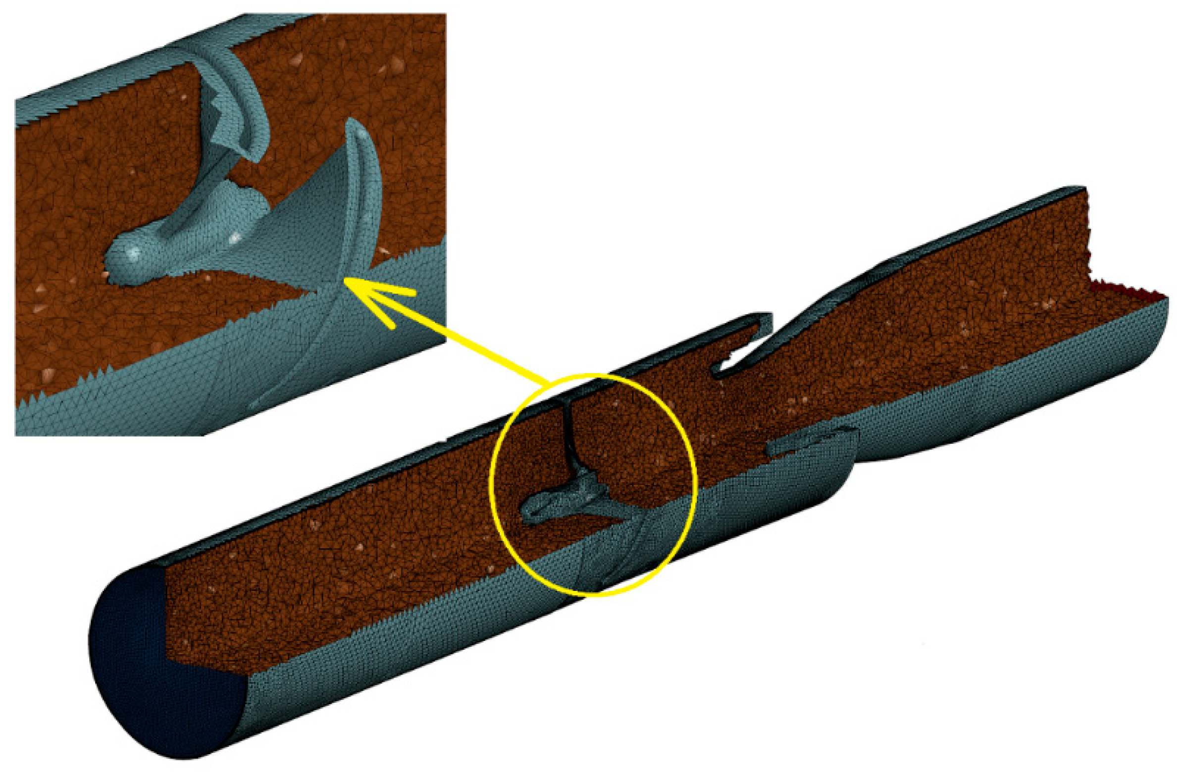
Cyclone geometry design, which is an element of the inlet air filter of the wheeled conveyor engine, was used to build axial-flow cyclone model. The cyclone geometry was obtained using the results of digital scanning with 3D ATOS IIe scanner produced by the GOM company. Information about shape and geometry of the cyclone was obtained, which was helpful in creating a digital copy of it.
Sets of points obtained as a result of the scanning, described by the x, y, z coordinates, reflect the surface of the scanned cyclone. These points, connected to form a mesh of triangles, reflect the shape of an object with a set of several million small triangles. On the basis of the obtained triangle mesh, a three-dimensional model of a cyclone is built, the geometry of which can be freely changed and numerical tests can be carried out. The advantage of the obtained model is also the fact that the modified model can be printed on a 3D printer and experimental tests can be performed, which was done in this work. Axial flow cyclone model is shown on
Figure 4.
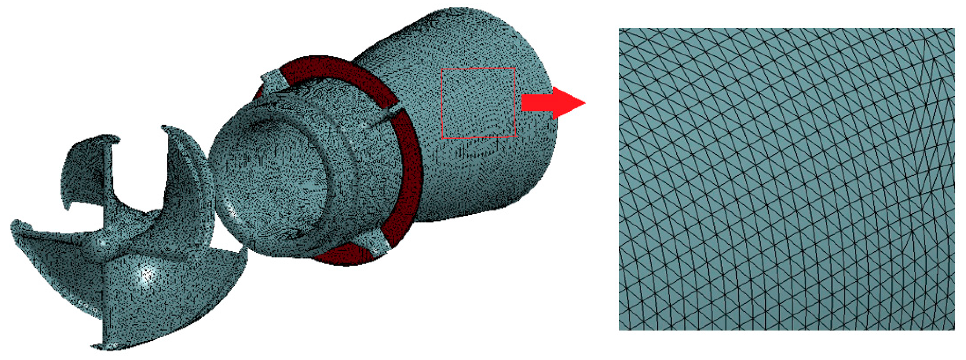
A very important aspect that should be taken into account when preparing a flow analysis is the correct behavior of the fluid on the interface “channel wall-fluid”. For this purpose, a transition from very narrow elements to increasingly larger so-called boundary layer zone. The parameter that helps determine the size of the first element as well as the boundary layer width is the Y + parameter.
For the model used in this study, the boundary layer thickness was
g = 0.5 mm, and height of the first element in this layer was
h = 0.01 mm. To generate finite volumes in the proposed model, an interpolation algorithm was used, which causes the mesh size to increase incrementally with a given step as it approaches the channel axis. As a result of the activities performed, the flow domain in axial flow cyclone was obtained, consisting of 2,314,958 finite volumes (
Figure 5). The initial boundary conditions used for the flow analysis are shown in
Figure 6. Detailed assumptions of the model and its detailed description are discussed in [
29].
5. Numerical and Experimental Test Results of Cyclone
Numerical tests results of three modification variants of axial flow cyclone structure are shown in
Figure 11,
Figure 12,
Figure 13,
Figure 14,
Figure 15 and
Figure 16. Cyclone separation efficiency change
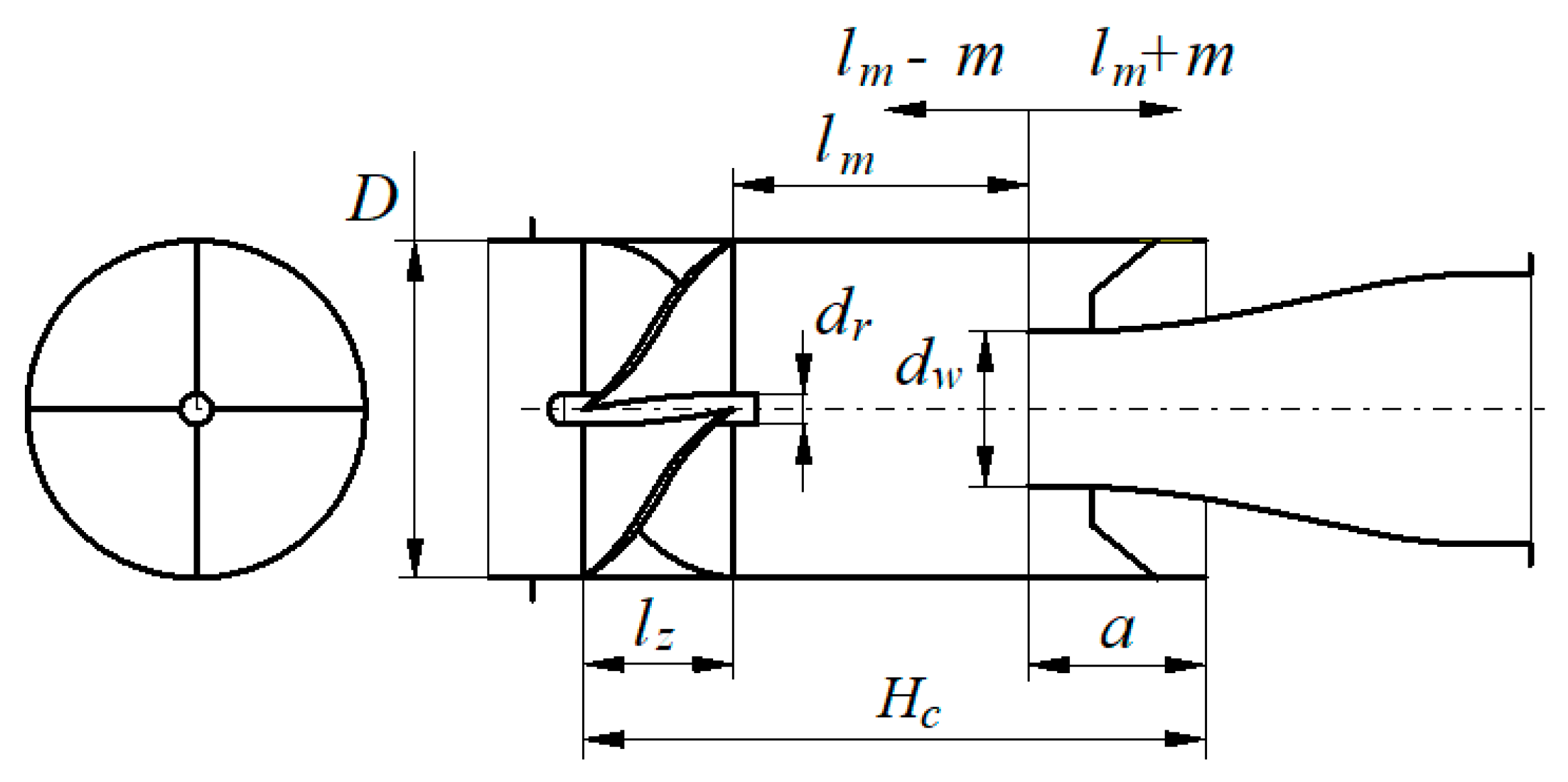
φ depending on the active length of the cyclone
lm (original value
lm = 36 mm) is shown in
Figure 11. Increasing the length
lm with the values:
m = 5 mm, 10 mm, 15 mm, 20 mm increases the cyclone separation efficiency in the range of 87–90%. Reducing the length of
lm by the same values of
m causes an intense decrease in separation efficiency of the cyclone to 79.5%.
Increasing cyclone separation length
lm naturally extends the spiral grain path until reaching the collecting chamber gap. Each rotation of the dust grain brings it closer to the inner wall of the cylindrical portion until it comes into contact, decelerates due to friction, and falls by gravity into the collecting chamber. The greater the separation length of the cyclone
lm, the greater the possible number of grain rotations. This is especially important for the dust grains that leave the blade close to the swirl core. Their path to the wall is much longer. Thus, the number of particles that reaches the wall of the inner cylindrical part and the collecting chamber is greater, which increases separation efficiency. As can be seen from
Figure 11, the intensity of the increase in separation efficiency decreases at higher values of
lm length. This can be explained by the fact that as one moves away from the swirler, the intensity of the swirl of the jet decreases due to friction, and thus the peripheral component of the velocity, which moves the grains to the cyclone wall, decreases. Hence, a smaller number will get into the collecting chamber.
Cyclone filtration change efficiency depending on the diameter of the inlet of the outlet pipe
dw (original value
dw = 21 mm) without changing the diameter of the outlet port
Dw and using the streamlined shape of the outlet tube is shown in
Figure 12. Increasing the diameter
dw by the following values:
w = 1 mm, 2 mm causes a decrease in and decreasing it by the same values increases the separation efficiency.
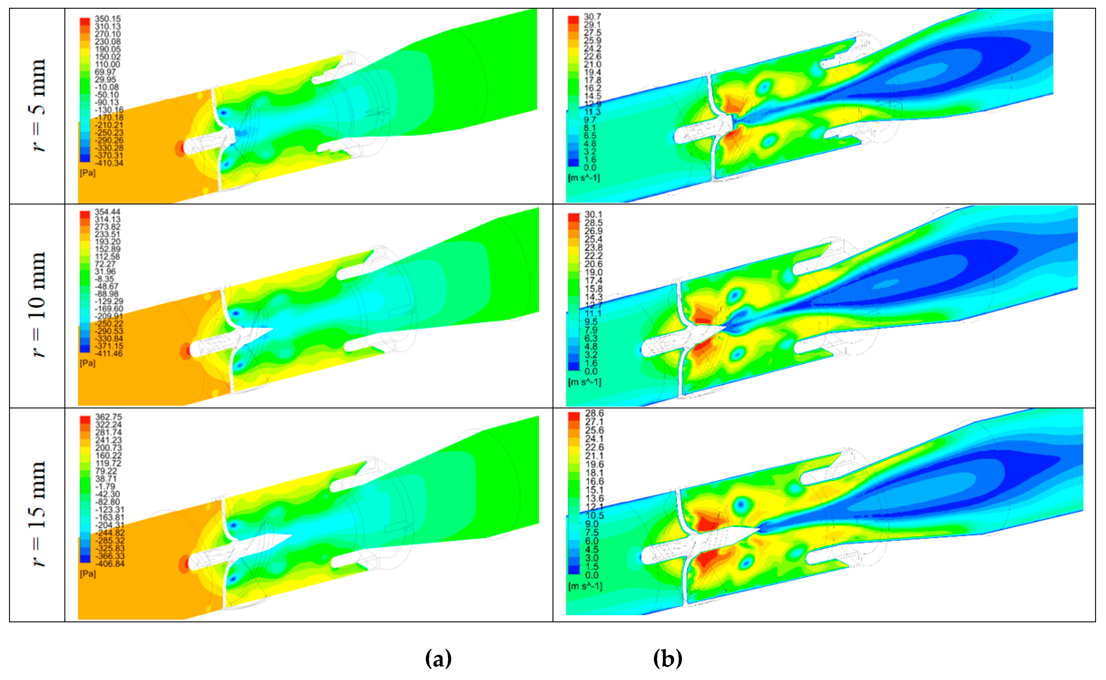
Reducing the diameter dw has a direct effect on increasing the width b of the collecting chamber, which enables the collection of a larger dust mass, which by the force of inertia reached the channel wall and slides along its cylindrical surface, making a helical movement. This increases separation efficiency. In close proximity of the channel wall, the turbulence of the jet decreases rapidly due to friction. For the same reason, the velocity of the grains in the circumferential direction and the inertia force acting on them in the radial direction also decreases. This increases the possibility of the separated dust being entrained by the air stream swirling towards the outlet tube. Greater width of the collecting chamber b prevents this phenomenon. However, increasing the width b is directly related to reducing the inner diameter of the inlet opening of the outlet tube dw, which causes an increase in speed at this point and an increase in pressure drop. For the inlet velocity υ0 = 10 m/s, the reduction (compared to the original) of the inner diameter of the tube dw by 2 mm increases separation efficiency from 87.5% to 90% and the increase in the flow velocity at the inlet opening of the outlet tube dw by over 20%, which significantly increases pressure drop of the cyclone
Extending the core length by the value:
r = 5, 10, 15 and 20 mm and ending it with a cone of angle
α as shown in
Figure 10 did not cause significant changes in cyclone separation efficiency.
Figure 13 shows pressure contours in the median plane. A negative pressure area is visible in the area between the swirl generator and the outlet pipe opening. Extending the core towards the outlet tube and ending it with a cone changed the pressure profiles (
Figure 13a) and increased velocity around the core (
Figure 13b).
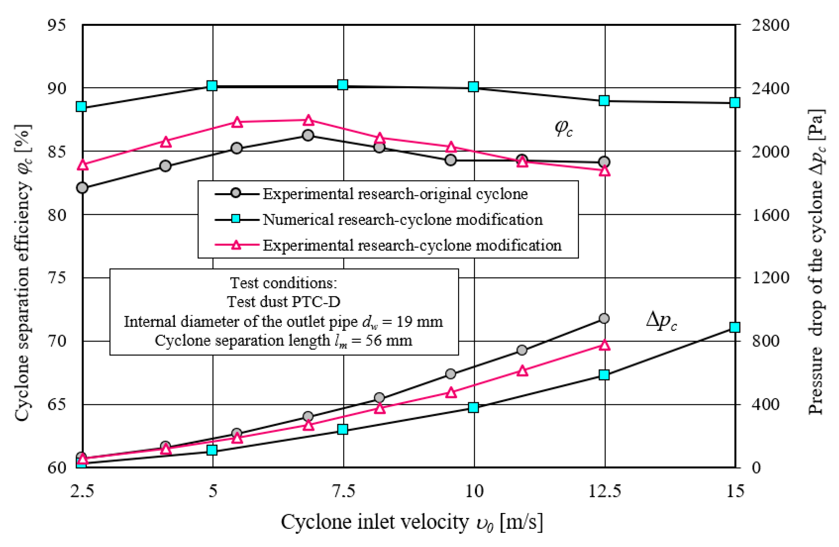
In order to verify the model, numerical tests were carried out on the characteristics of the cyclone filtration efficiency ϕc = f(υ0) depending on the inlet velocity in the range υ0 = 2.5–15 m/s. Tests included a modified cyclone model, which had the separation length increased by 20 mm compared to the original (lm = 56 mm) and cyclone inlet pipe diameter decreased by 2 mm (dw = 19 mm). For these parameters, at inlet velocity of the cyclone υ0 = 10 m/s, the cyclone reached maximum values of separation efficiency. A model with such parameters was printed using the additive manufacturing technique, and then its experimental tests were carried out. Separation efficiency characteristics ϕc = f(υ0) and pressure drop characteristics Δpc = f(υ0) and depending on the inlet velocity in the range of υ0 = 2.5–12.5 m/s were made. The same scope of experimental research covered the original cyclone before the modification.
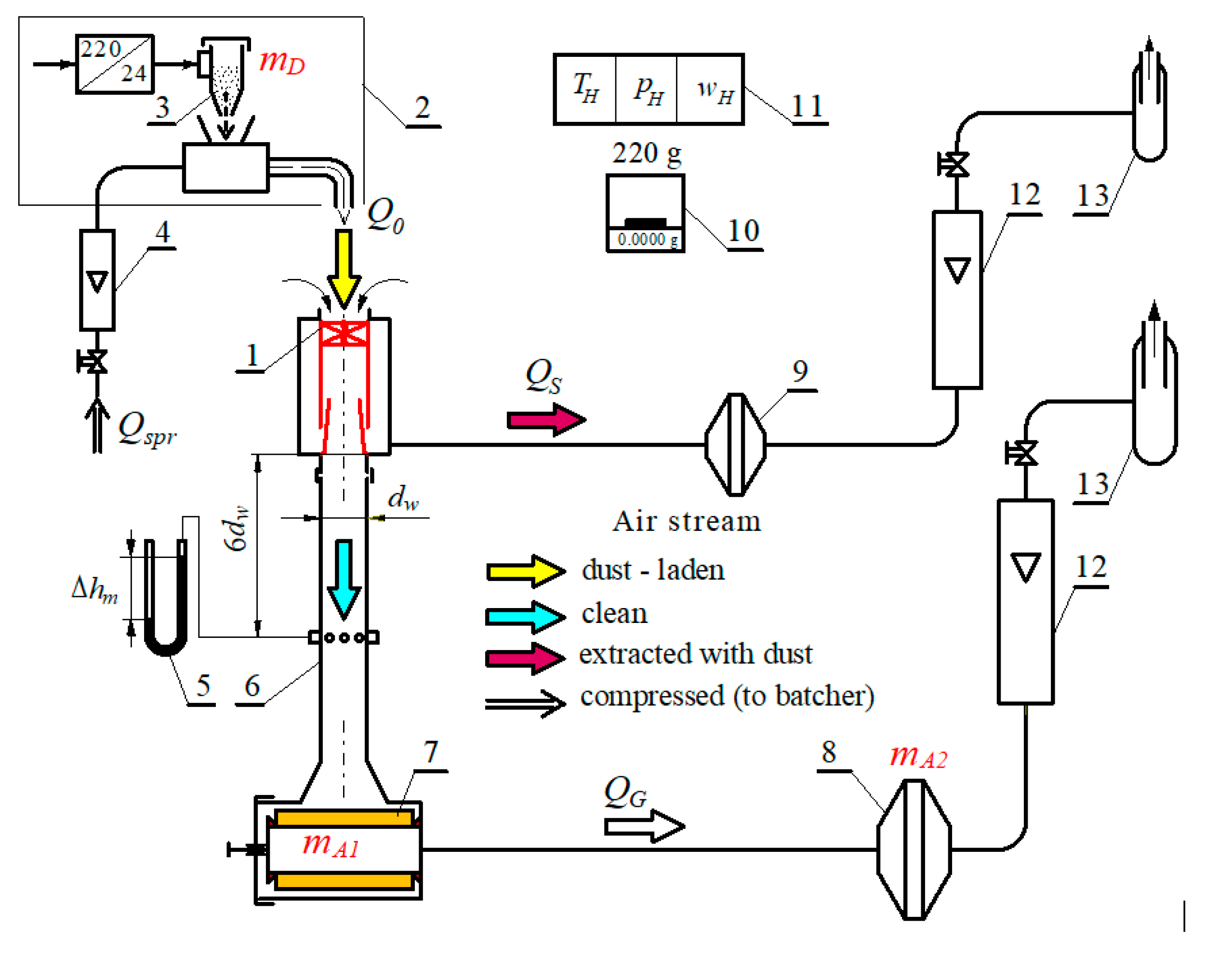
Experimental tests of axial flow cyclone were carried out on a stand built in accordance with ISO 5011 (
Figure 14). ”Fine” polydisperse test dust with particle size
dzmax = 80 µm was used (
Table 1) and chemical composition (
Table 2) which was supplied to the cyclone by compressed air dispenser to obtain a dust concentration of 0.5 g/m
3 at the cyclone inlet.
To determine separation efficiency
φc of the axial-flow cyclone, the mass method was used, consisting in measuring the dust mass retained by the cyclone
mZc and the mass of dust
mDc delivered to tested cyclone and dust mass retained by the absolute filters
mA1 and
mZA2 at a specified time
tp. Dust mass supplied to the cyclone and the dust mass retained by the absolute filters were determined as the difference between the masses of the dust container and filters before and after the measurement. The measurements were performed for a fixed value of the inlet air stream to the cyclone
Q0. There were 8 values of air flows in the range
Q0 = 10–55 m
3/h at equal intervals, which correspond to the inlet velocity into the cyclone in the range
υ0 = 2.5–12.5 m/s. For each determined value of the air stream
Q0,
j = 5 measurement cycles were performed, during which dust masses necessary to determine the cyclone separation efficiency were determined. For this purpose, an analytical balance with a measuring range of 220 g and an accuracy of 0.1 mg was used. After each measurement cycle
j, separation efficiency was determined using the following relationship, and then the average of the measurements was calculated:
Dust mass retained by the
mZcj cyclone was calculated using the indirect method from the following formula:
The pressure drop in the tested axial flow cyclone Δ
pcj was determined after each measurement cycle on the basis of the measured static pressure drop Δ
hmj in the outlet pipe after the cyclone at a distance of 6
dw from the end of the cyclone outlet pipe, where
dw-internal diameter of the cyclone outlet pipe. Δ
hmj was read in mm of H
2O on a U-tube liquid manometer. The value of the pressure drop was calculated using:
where:
ρm—manometric liquid density [kg/m
−3],
ρH—air density [kg/m
−3],
g—gravity acceleration [m/s
2].
Results of the numerical and experimental tests of separation efficiency
ϕc =
f(
υ0) and the pressure drop Δ
pc =
f(
υ0) depending on the inlet velocity
υ0 of the modified cyclone and the results of the experimental tests of the cyclone in the original version are presented in
Figure 15.
Cyclone separation efficiency characteristics obtained from numerical tests have a course similar to the characteristics resulting from experimental tests of the original and modified cyclone, while the efficiency from numerical tests obtain higher values in the entire range of the inlet velocity used.
Differences in cyclone separation efficiency characteristics, as to their course and value, should be explained by the adopted model of dust particle size composition. The actual dust consists of several components, each with a different density. Moreover, the shapes of the real dust grains are irregular. The adopted dust model has one fixed density (silica) and dust grains have the shape of a sphere. These factors have a decisive influence on the trajectory of dust particles and their reaching the collecting chamber.
Separation efficiency characteristics of original and modified cyclones follow a similar course, but differ in value. As the inlet velocity
υ0 increases, the separation efficiency increases, and after reaching the maximum value for
υ0 = 6.8 m/s, then its slow decrease occurs. Such a course of cyclone characteristic
ϕc =
f(
υ0) is consistent with the results of other studies presented in the literature [
79].
A cyclone with modifications achieves a higher separation efficiency than the original cyclone in the whole range of inlet velocity υ0, which confirms the correctness of the design changes introduced in the cyclone.
At the inlet velocity of
υ0 = 6.8 m/s, the efficiency increased from
ϕc = 86.2% to
ϕc = 87.5%, i.e., by 1.5%. Below the speed
υ0 = 6.8 m/s, the increase in separation efficiency of the cyclone caused by the introduced design changes is clearly greater. This enables the cyclone to operate at lower air stream velocities, i.e., smaller pressure drops, the value of which depends on the speed, based on the equation:
As the inlet velocity
υ0 increases, pressure drop of tested cyclones increases parabolically, which results from the above equation. A cyclone with the introduced modifications achieved pressure drop lower by about 15% than the original cyclone, which will result in lower engine power losses. Obtaining lower pressure drop of the cyclone results from the streamlined shapes introduced at the inlet of the guide vanes and the outlet tube (
Figure 8). Characteristics analysis of
ϕc =
f(
υ0) and Δ
pc =
f(
υ0) (
Figure 15) shows that the cyclone should not operate above the inlet velocity of
υ0 = 10 m/s, because then its operation becomes ineffective. There is then a decrease in separation efficiency and an increase in the cyclone pressure drop.
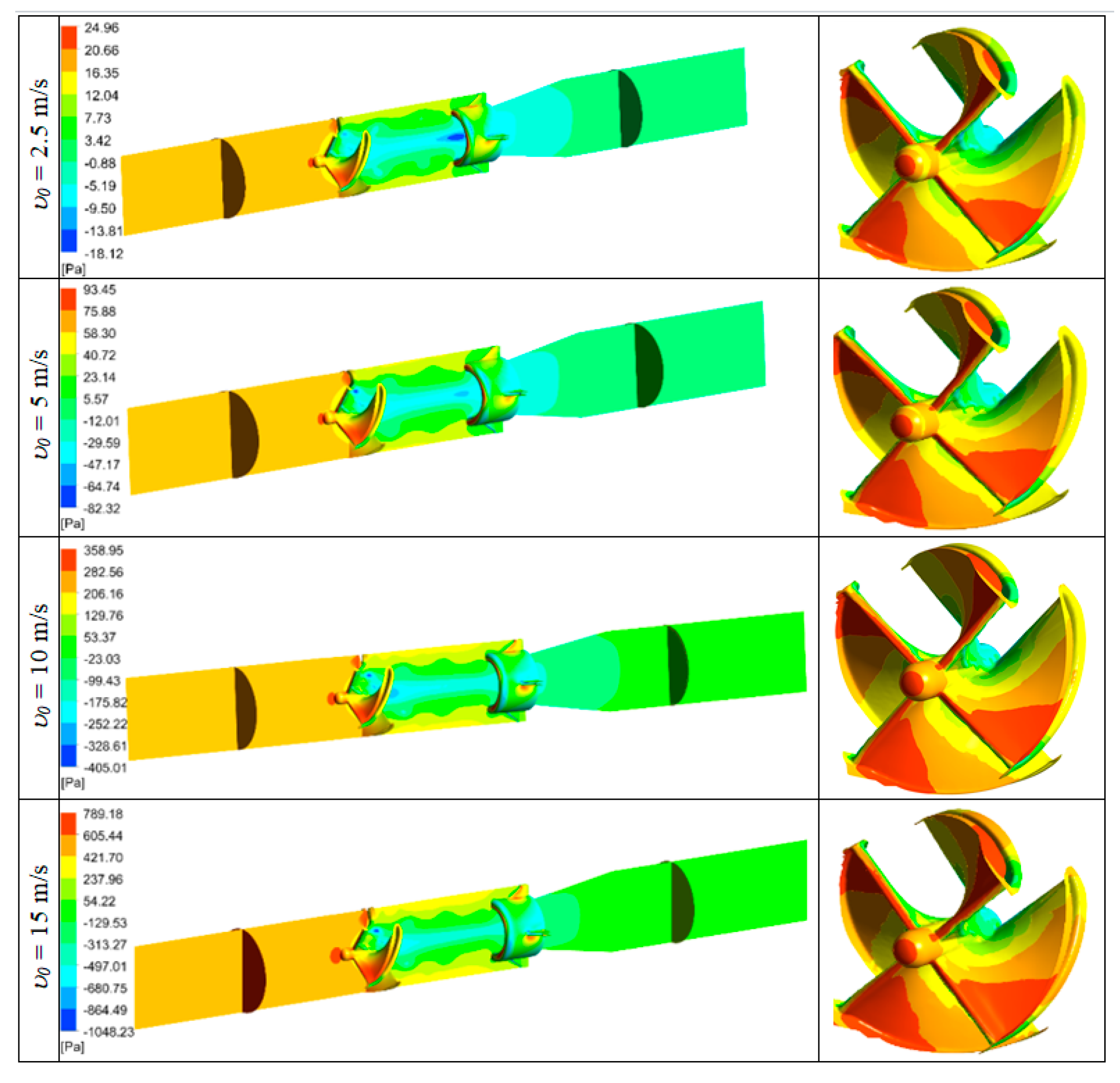
Test results for the values and pressure profiles
pc for the cyclone model with the maximum value of the separation length
lm = 56 mm and the minimum diameter of the inlet pipe
dw = 19 mm depending on the inlet velocity in the range
υ0 = 2.5–15 m/s are shown in
Figure 16.
The highest values of pressure
pc were recorded only on a small initial part of the surface of swirler blades. Field of highest pressure starts from the front of vanes towards the cylindrical part of the hull. Inclination of steering wheel at this point is much greater than near the spindle. For the inlet velocity
υ0 = 2.5 m/s, the pressure in the front part of the steering wheel is
pc1 = 24. With the increase of the inlet velocity
υ0, the pressure values on a part of the surface of the blades are increasing. For inlet velocity
υ0 = 5 m/s, the pressure has the value
pc1 = 93 Pa, for
υ0 = 10 m/s,
pc1 = 207 Pa, and for
υ0 = 15 m/s,
pc1 = 789 Pa. As the air stream moves to the swirler’s outlet, the pressure decreases, but the intensity of decrease is greater in the center of the swirler (near the core) at the point where the blade contacts the cylindrical part of the cyclone hull. As a result, there is a negative pressure in the central part behind the swirler, the greater the greater the inlet velocity. For the inlet velocity
υ0 = 2.5 m/s, the pressure downstream of the swirler (spindle end) has the value
pc2 = −5.19 Pa, for
υ0 = 5 m/s
pc2 = −29.6, and for
υ0 = 15 m/s,
pc2 = −497 Pa (
Figure 16).
Figure 15 shows characteristics Δ
pc =
f(
υ0) of pressure drop of the cyclone after modification, obtained on the basis of the numerical test results, as the pressure difference between the
pc1 inlet and
pc2 outlet of the cyclone, according to the following equation:
As the inlet velocity υ0 (air stream) increases, the flow resistance Δpc = f(υ02) increases in a parabolic manner, which is consistent with the literature. Characteristics of the cyclone Δpc = f(υ0) obtained from numerical tests have a course similar to the characteristics resulting from experimental tests of the original cyclone, with pressure drop values from the experiment slightly higher in the entire range of the inlet velocity υ0 = 2.5–12.5 m/s.


