Article

Research on Zero-Voltage Ride Through Control Strategy of Doubly Fed Wind Turbine

1
College of New Energy, China University of Petroleum (East China), Qingdao 266580, China
2
China Electric Power Research Institute, Beijing 100192, China
*
Author to whom correspondence should be addressed.
Energies 2021, 14(8), 2287; https://doi.org/10.3390/en14082287
Submission received: 9 March 2021 / Revised: 8 April 2021 / Accepted: 11 April 2021 / Published: 19 April 2021
(This article belongs to the Section A3: Wind, Wave and Tidal Energy)

Abstract

:
With the rapid increase in the proportion of the installed wind power capacity in the total grid capacity, the state has put forward higher and higher requirements for wind power integration into the grid, among which the most difficult requirement is the zero-voltage ride through (ZVRT) capability of the wind turbine. When the voltage drops deeply, a series of transient processes, such as serious overvoltage, overcurrent, or speed rise, will occur in the motor, which will seriously endanger the safe operation of the wind turbine itself and its control system, and cause large-scale off-grid accident of wind generator. Therefore, it is of great significance to improve the uninterrupted operation ability of the wind turbine. Doubly fed induction generator (DFIG) can achieve the best wind energy tracking control in a wide range of wind speed and has the advantage of flexible power regulation. It is widely used at present, but it is sensitive to the grid voltage. In the current study, the DFIG is taken as the research object. The transient process of the DFIG during a fault is analyzed in detail. The mechanism of the rotor overcurrent and DC bus overvoltage of the DFIG during fault is studied. Additionally, the simulation model is built in DIgSILENT. The active crowbar hardware protection circuit is put into the rotor side of the wind turbine, and the extended state observer and terminal sliding mode control are added to the grid side converter control. Through the cooperative control technology, the rotor overcurrent and DC bus overvoltage can be suppressed to realize the zero-voltage ride-through of the doubly fed wind turbine, and ensure the safe and stable operation of the wind farm. Finally, the simulation results are presented to verify the theoretical analysis and the proposed control strategy.

1. Introduction

Driven by the rapid development of the global economy, the wind energy market is developing rapidly, and the installed capacity of global wind power is expanding promptly. With the continuous development of wind power generation, wind farm control and its impact on the security and stability of the power grid has become one of the important issues in the development of wind power. Voltage sag is a common fault form in the wind power system. For the conventional wind power generation system, when the fault voltage suddenly drops to zero, the wind turbine will implement passive self-protection and immediately disconnect, regardless of the duration and severity of the fault, to maximize the safety of the wind turbine. However, the passive protection disconnection of the wind turbine will increase the difficulty of recovery of the whole system, and may even aggravate the fault, eventually leading to the disconnection of other wind generating sets in the system. This situation was allowed for a long time in the past, but with the increasing proportion of wind power capacity in the total power grid capacity, the disconnection of wind turbines may cause voltage collapse and serious frequency oscillation of power grid, which will bring huge losses to industrial production [1,2,3,4]. Therefore, many countries in the world have incorporated the zero-voltage ride through (ZRVT) capability requirements into their grid guidelines. The zero voltage ride through is based on the concept of low voltage ride through (LVRT), which refers to the ability of the wind turbine to maintain continuous operation without disconnection when the grid voltage drops to 0 completely [5]. Due to the obvious differences in the structures of various wind turbines, there are some differences in the technical implementation of zero-voltage ride through. At present, the doubly fed induction generator has become the mainstream model in the wind power market due to its good performance of power decoupling control, small converter capacity, and wide speed regulation range [6]. However, due to the special topology structure that the stator side of the doubly fed induction generator (DFIG), which is directly connected to the power grid, it is particularly sensitive to grid voltage fault, its ability to resist grid disturbance is relatively weak, and due to the limitation of converter power, the fault ride through the capability of the DFIG is reduced [7]. Therefore, it is particularly important to study the zero-voltage ride through capability of this type wind turbine for the security and stability of the power grid.
The main objectives of the research on the control strategy of the DFIG under voltage sag are that the rotor side converter current, the DC (direct current) bus voltage and the rotor speed do not exceed the limit. In the control of the rotor side converter current beyond the limit, the method of restraining the stator flux linkage and changing the connection mode of stator winding can reduce the rotor overcurrent of the wind turbine [8]. The current tracking control strategy was studied in Q. Huang et al. [9]. The stator current is multiplied by the appropriate coefficient as the instruction value of the rotor current to reversely track the stator current for eliminating the electromagnetic torque ripple. The crowbar hardware protection circuit was proposed in H. Jiang et al. [10,11,12]. However, in the case of severe voltage sag, increasing the resistance value of the protection circuit to suppress the rotor current will raise the DC bus voltage. In M. Wang et al. [13], a new type of resistance capacitance rotor crowbar circuit structure was proposed to improve the power characteristics during the fault. However, the analysis and solution process are complex, and the setting of the crowbar resistance is not involved. The fault current limiters were used to reduce the rotor current and the torque oscillation, but most of them cannot be applied to industry without special engineering measures [14,15,16,17]. In terms of the control strategy of the grid side converter, to improve the dynamic control performance of the grid side converter, double PI control was applied to eliminate the fluctuation of the output power of the wind power system [18,19,20]. The terminal sliding mode control technology was proposed in M. Firouzi et al. [21,22]. It can reduce the fluctuation of the DC bus voltage effectively in case of fault, but it has not been applied in the field of zero-voltage ride through at present. In the aspect of controlling the rotor speed, the authors in [23,24] proposed adjusting the speed by controlling the pitch angle.
The above control strategy is only applicable to the low voltage ride through of the DFIG. The single control strategy cannot realize the zero-voltage ride through of the DFIG. Up to now, as for the research on the zero-voltage ride through of doubly fed induction generators, scholars at home and abroad have made many achievements in low voltage ride through technology. Few papers and results on zero-voltage ride through of the DFIG technology have been published. The progress of zero-voltage ride through research is shown in H. Zhao et al. [25,26,27,28]. The authors in [25,26] put forward the integrated control strategy under fast pitch angle control, multistage protection circuit response and improved excitation control strategy during ZVRT. The authors in [27] focused on the dynamic reactive current injection during zero-voltage ride through of the DFIG. In E. Cai et al. [28], a pitch system control scheme for ZVRT that includes pitch system modeling, control logic, control circuits, and overspeed protection control was proposed. In short, the availability of published papers and results on zero-voltage ride through technology is limited.
The contributions of this paper are as follows:
(1)
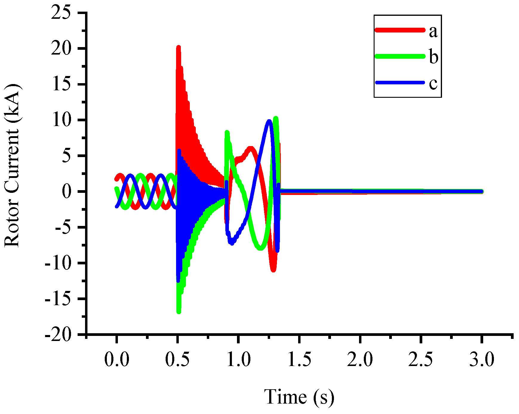
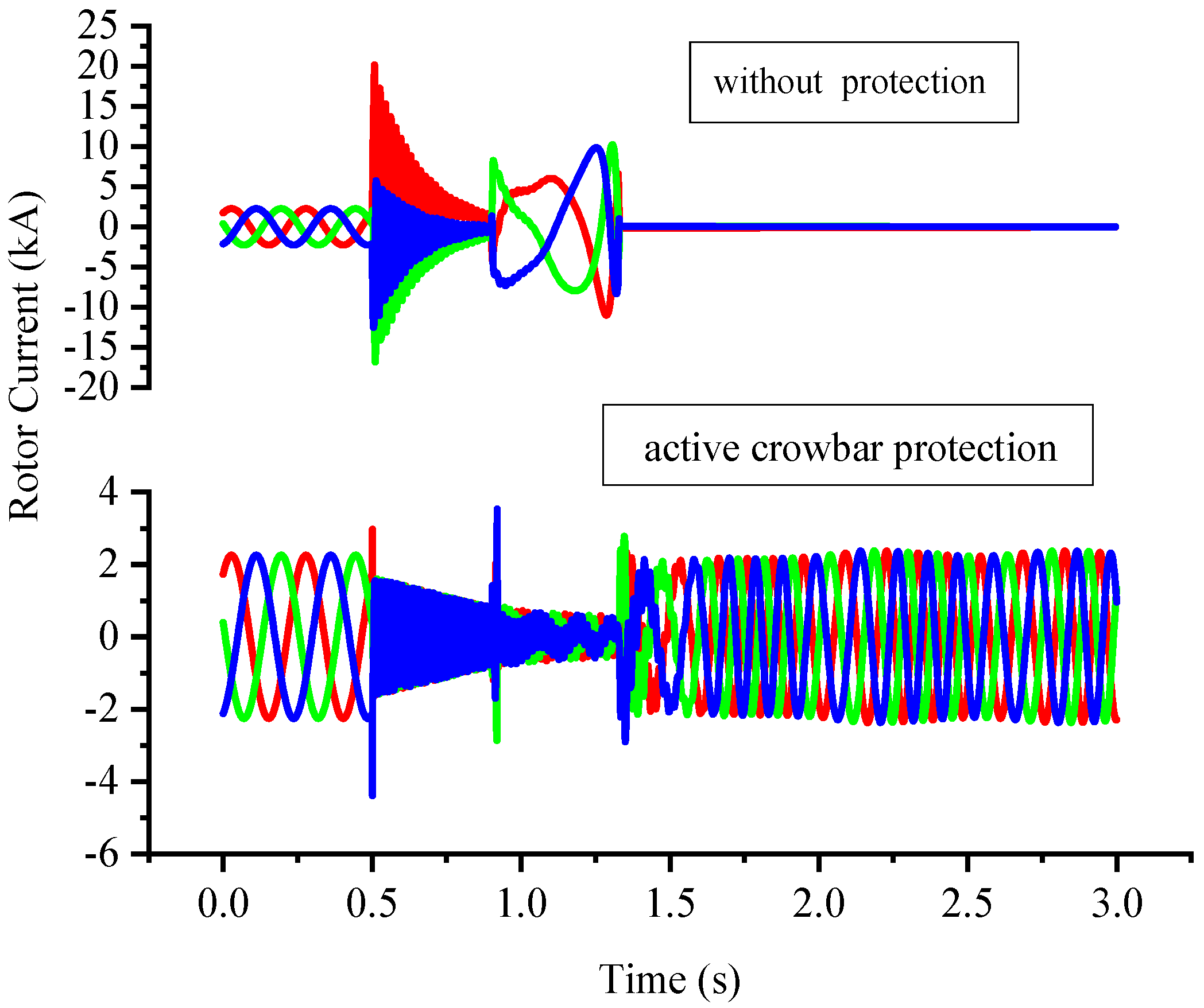
The transient process of the DFIG during three-phase short-circuit fault is analyzed in detail. The mechanism of the rotor overcurrent and the DC bus overvoltage of the DFIG during a fault is studied and verified by simulation.
(2)
The resistance value and switching strategy of the active crowbar hardware protection circuit are determined, and the control strategy of the grid side converter is improved.
(3)
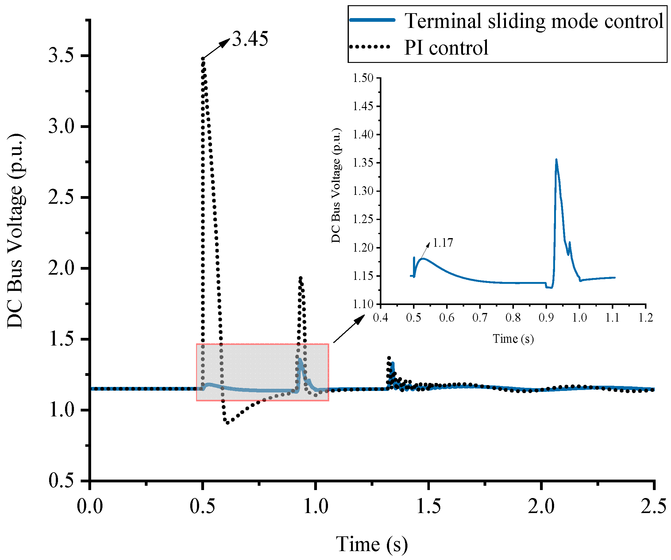
A cooperative control strategy based on extended state observer (ESO), terminal sliding mode control and active crowbar protection circuit is proposed.
(4)
Through the coordinated control, DC bus voltage rising, which is caused by the increase in the protection circuit resistance value to restrain rotor current, is reduced under the condition of severe voltage sag. In other words, the crowbar hardware protection circuit is improved, which is not only suitable for low voltage ride through DFIG. The simulation results show that the zero-voltage ride through of the DFIG can be realized.
The paper is organized as follows. Section 2 describes the mechanism of the rotor overcurrent and DC bus overvoltage of the doubly fed wind turbine during a three-phase short-circuit fault. Section 3 provides coordinated control measures for zero-voltage ride through of a doubly fed wind turbine. Section 4 provides the results and performance verification of the proposed control strategy. Finally, Section 5 summarizes the conclusions.

2. Zero-Voltage Ride through Mechanism of Doubly Fed Wind Turbine

2.1. Transient Analysis of Stator and Rotor under Three-Phase Short-Circuit Fault

The most serious three-phase symmetrical short-circuit fault is selected for analysis in order to better understand the transient characteristics of the stator and rotor circuit of the doubly fed wind turbine when the grid voltage decreases.
Figure 1 shows the equivalent physical model of the doubly fed induction generator. The stator side three-phase windings A, B and C are stationary. The rotor side three-phase windings a, b and c follow the rotor rotating anticlockwise at the angular velocity of ω r . θ r is the electrical angle between rotor a-axis and stator A-axis. According to convention, the positive direction of the coil axis is defined as the positive direction of the coil magnetic field axis. The magnetic field generated by the positive direction of the voltage and current is defined as the positive direction of the magnetic field. The rotor side parameters are converted to the stator side, and the positive direction of each physical quantity adopts the motor convention. According to Figure 1, the voltage and flux linkage equations in the three-phase static ABC coordinate system can be established.
The voltage equation of stator three-phase circuit is shown in Equation (1) and the voltage equation of the rotor three-phase circuit is shown in Equation (2).
{ u s A = R s i s A + d d t ψ s A u s B = R s i s B + d d t ψ s B u s C = R s i s C + d d t ψ s C
{ u r a = R r i r a + d d t ψ r a u r b = R r i r b + d d t ψ r b u r c = R r i r c + d d t ψ r c
where: u s A , u s B and u s C are stator side three-phase terminal voltages of the DFIG; u r a , u r b and u r c are rotor side three-phase terminal voltages of the DFIG, respectively; i s A , i s B and i s C are stator side three-phase currents of the DFIG, respectively; i r a , i r b and i r c are rotor side three-phase currents of the DFIG, respectively; ψ s A , ψ s B and ψ s C are stator side three-phase flux linkage of the DFIG; ψ r a , ψ r b and ψ r c are rotor side three-phase flux linkage of the DFIG; R s and R r are equivalent resistances of stator side and rotor side of the DFIG, respectively.
There are self-inductance L and mutual-inductance M between windings in stator side and rotor side of the DFIG, so the flux linkage equation is shown as follows.
[ ψ s A ψ s B ψ s C ] = [ L A M A B M A C M A B L B M B C M A C M B C L C ] [ i s A i s B i s C ] + [ M A a M A b M A c M B a M B b M B c M C a M C b M C c ] [ i r a i r b i r c ]
[ ψ r a ψ r b ψ r c ] = [ M A a M B a M C a M A b M B b M C b M A c M B c M C c ] [ i s A i s B i s C ] + [ L a M a b M a c M a b L b M b c M a c M b c L c ] [ i r a i r b i r c ]
From Equations (1)–(4), the vector equation of the doubly fed wind turbine in space static coordinate can be obtained, as shown in Equation (5):
u s = R s i s + p ψ s + j ω s ψ s u r = R r i r + p ψ r + j s ω s ψ r ψ s = L s i s + L m i r ψ r = L m i s + L r i r
where: u , i and ψ are voltage, current and flux linkage, respectively; subscripts s and r represent stator and rotor, respectively; L s , L r and L m are self-inductance of stator and rotor windings and mutual-inductance between stator and rotor, respectively; ω s is synchronous angular velocity of power grid; s is slip ratio; p is differential operator; j is imaginary unit.
From Equation (5), the relationship between stator and rotor current and flux linkage can be obtained as follows:
i s = ( L r ψ s L m ψ r ) / ( L s L r L m 2 ) i r = ( L s ψ r L m ψ s ) / ( L s L r L m 2 )
Since the excitation inductance of the doubly fed wind turbine is much larger than the leakage inductance of stator and rotor, namely L m L σ s and L m L σ r . Additionally, L s = L m + L σ s , L r = L m + L σ r . Equation (6) can be simplified as follows:
i s i r = ψ s ψ r L σ r + L σ s = ψ s ψ r L σ
L σ = L σ r + L σ s . It is the total leakage reactance of stator and rotor. It can be seen from Equation (7) that the current vectors of stator and rotor are equal in magnitude and opposite in direction.
At the same time, the stator and rotor flux linkage relationship can be simplified as:
ψ r = ψ s ψ σ s + ψ σ r ψ s + L σ i r
When the doubly fed wind turbine operates stably, the stator and rotor flux linkage remain relatively static. The three-phase short-circuit fault at the grid point will cause the stator terminal voltage to drop to zero. According to the flux conservation, the transient DC component of flux linkage will be generated in the circuit, and its attenuation time is determined by the stator side resistance and equivalent inductance.
T s = L s R s = L σ s + L σ r L m L σ r + L m R s
At the same time, the stator flux will also produce some AC (alternating current) components with small amplitude, so the stator flux can be shown in Equation (10).
ψ s = ψ s d c + ψ s a c ψ s d c
Similarly, the rotor flux space vector can be expressed as:
ψ r = ψ r d c + ψ r a c
ψ r d c and ψ r a c are the DC component in the rotor flux and the AC component in the rotor flux caused by stator excitation at the moment of grid voltage drop. Neglecting the AC component is as follows:
ψ r ψ r d c
Therefore, the time-domain form of stator and rotor flux vector can be expressed as follows:
ψ r ψ r d c e j ψ r t = ψ r d c 0 e t / T r e j ω r t ψ s ψ s d c 0 e t / T s
where, ψ s d c 0 and ψ r d c 0 represent the effective value of stator and rotor flux linkage at the moment of short-circuit fault, respectively; transient time constant of the rotor with stator short-circuit T r = L r R r = L σ r + L σ s L m L σ s + L m R s .
By substituting Equation (13) into Equation (7), the expression of stator and rotor short-circuit current after three-phase short-circuit fault can be obtained:
i s i r = ψ s ψ r L σ = ψ s d c ψ r d c L σ = ψ s d c 0 e t / T s ψ r d c 0 e t / T r e j ω r t L σ
It can be seen from Equation (14) that the rotor current is mainly composed of two parts at this time. First, it is induced by the DC component of stator flux linkage, and it will be affected by the stator resistance. The component gradually decays with the stator time constant T s until it drops to zero; The other part is induced by the DC component of the rotor flux linkage, which will gradually decay to zero with the rotor time constant T r due to the influence of the rotor structure.
During the short-circuit fault, the DC component of stator and rotor flux linkage only forms circuit in the leakage magnetic circuit of stator and rotor, so the fault current induced by three-phase fault is only determined by the DC component of stator and rotor flux linkage and the transient short-circuit inductance of stator and rotor. Usually, the stator and rotor leakage inductance of large-scale doubly fed wind turbine are relatively small, about 0.1 times the standard unit value. In this way, the fault current generated by the DC component of the flux linkage will be large, even up to 5 to 10 times the rated value, which will bring serious damage to the doubly fed wind turbine system. Therefore, the rotor overcurrent must be restrained during the zero-voltage ride through of the DFIG.
Based on the model of 5 MW DFIG connected to 3.3 kV distribution network and outputting power to 30 kV power grid, the transient response of the DFIG with three-phase symmetrical fault is simulated and verified. At 0.5 s, the three-phase short-circuit fault occurs on the point of common coupling (PCC) bus of DFIG, and the fault is cleared at 0.9 s. The stator resistance and stator inductance are 0.003 p.u. and 0.125 p.u., respectively. The rotor resistance and rotor inductance are 0.004 p.u. and 0.05 p.u., respectively. The self-inductance is 2.5 p.u. The change process of the rotor current during the fault is shown in Figure 2.
It can be seen from Figure 2 that the peak current of the rotor increases from 2.258 kA to 20.075 kA during the fault, which is about 9 times the rated value. It is consistent with the above theoretical analysis. Therefore, the research of zero-voltage ride through control technology of the DFIG must restrain the rotor overcurrent.

2.2. Transient Analysis of the DC Bus

DC bus is the bridge of energy conversion between rotor side converter and grid side converter of the doubly fed wind turbine. The stability of the DC bus voltage is the precondition to ensure the normal operation of the rotor side converter, and its stability is mainly controlled by grid side converter. Therefore, the stability of the DC bus voltage is very important.
When the power system voltage is normal, the doubly fed wind turbine works in a stable state, and the DC bus voltage remains at a constant value. The fluctuation of the DC bus voltage mainly depends on the active power exchanged with rotor side converter and grid side converter.
1 2 C d u d c 2 d t = P d c 2 P d c 1
where, P d c 1 is the instantaneous active power transmitted from the DC bus to rotor side converter; P d c 2 is the instantaneous active power injected from the grid side converter to the DC bus.
Ignoring the various losses of energy flowing from the grid through the grid side converter, the active power absorbed by the grid side converter from the grid is approximately equal to the instantaneous active power injected into the DC bus by the grid side converter.
P g = P d c 2
Substituting Equation (16) into Equation (15), Equation (17) can be obtained:
1 2 C d u d c 2 d t = P g P d c 1 = u s i g d P d c 1
It can be concluded from Equation (17) that the change of the DC bus voltage mainly depends on the grid voltage u s , the active power P d c 1 transmitted by DC bus to the rotor side converter and the d-axis input current i g d of the grid side converter. When the grid voltage drops suddenly, u s gets smaller instantaneously. The serious overvoltage and overcurrent phenomenon on the rotor side lead to the DC bus becoming unable to normally deliver active power to the rotor. The reduction in grid voltage also makes the grid and grid side converter unable to continue to maintain normal capacity exchange, which indirectly leads to the change of i g d . Affected by these factors, the DC bus will occur serious voltage fluctuation during the fault period. Therefore, the DC bus overvoltage must be restrained during the zero-voltage ride through of the DFIG.
Through simulation, the transient response of the DC bus under three-phase short-circuit fault is verified. At 0.5 s, three-phase short-circuit fault occurs in the DFIG parallel point PCC bus, and the fault is cleared at 0.9 s. The change process of the DC bus voltage during the fault is shown in Figure 3.
It can be seen from Figure 3 that the DC bus voltage increases from 1.150 p.u. to 24.895 p.u., which is about 22 times the rated voltage. It is consistent with the above theoretical analysis. Therefore, the research of the zero voltage ride through control technology of the DFIG must restrain the DC bus over voltage.

3. Control Measures for Zero-Voltage Ride Through of the Doubly Fed Wind Turbine

3.1. Control Measure for Rotor Side of the Doubly Fed Wind Turbine

3.1.1. The Structure and Principle of Active Crowbar Protection Circuit

In order to protect the rotor side converter from damage in case of severe fault, the hardware protection circuit adopts the active crowbar protection circuit, as shown in Figure 4. The switching control switch of the active crowbar protection circuit adopts power electronic devices that can be turned off at an appropriate time after the protection circuit acts, so as to ensure that the rotor side converter can be recovered without power grid disconnection. It can shorten the transition time from the asynchronous motor operation state to the doubly fed speed control state, which is conducive to the stable operation of the wind turbine and power grid. The active crowbar protection circuit is composed of a three-phase AC switch (SCR) and bypass resistance. This circuit has low cost and strong ability to withstand overcurrent. It provides a path for the large current that may appear on the rotor side during the fault period to protect the rotor side converter. When the grid voltage drop occurs and recovers, the rotor side converter can remain connected with the rotor. After the fault is eliminated, the bypass resistance is cut off to make the system quickly return to normal operation.

3.1.2. Resistance Value Determination of Active Crowbar Protection Circuit

The resistance of the crowbar can dampen the rotor flux linkage, but its value will affect the transient stability of the system and the wind turbine is cleared during and after the fault. With a smaller resistance value, it cannot effectively limit the rotor overcurrent; with a greater resistance value, the rotor overcurrent decays faster, but the potential difference between its two ends will increase. When the crowbar circuit is put into operation, the DC bus capacitor will be recharged, thus affecting the safe operation of the bus capacitor. Moreover, the greater resistance value causes the wind turbine to absorb more reactive power from the system. Therefore, it is very important to determine the range of the crowbar resistance.
When the DFIG is in steady-state operation, the stator is directly connected to the grid, and the stator resistance can be ignored, then the stator flux linkage is kept constant and ahead of the grid voltage vector, as shown in Equation (18).
{ ψ s = U s j ω s = U s e j ω s t j ω s ψ r = L r L m · U s e j ( ω s t θ ) j ω s
where: ψ s , ψ r are stator and rotor flux; U s is stator voltage; ω s is stator angular velocity; L r , L m are rotor inductance and mutual inductance; θ is rotor angle.
If three-phase short-circuit fault occurs in the power grid at the time t = 0 , the fault initial value of stator and rotor flux linkage are as follows:
{ ψ s 0 = U s 0 j ω s ψ r 0 = L r L m · U s 0 e j ( ω s t θ ) j ω s
where: ψ s 0 , ψ r 0 are the fault initial value of stator and rotor flux linkage; U s 0 is the initial value of stator voltage.
Then, the flux linkage of stator and rotor after fault are as follows:
{ ψ s = U s 0 j ω s e t / T s ψ r = L r L m · U s 0 e j ( ω s t θ ) e t / T s j ω s
According to Equation (20), the rotor current after fault is approximately as follows:
i r U s 0 j ω s L s + R c r o w ( e t / T s L r L m e j ( ω s t θ ) e t / T s )
Therefore, the maximum value of the rotor current is:
I max = U s / ( ω s L s ) 2 + R c r o w 2
In order to protect the rotor side converter, the maximum fault current should not exceed the safe current I s a f e , that is R c r o w = ( U s / I s a f e ) 2 ( ω s L s ) 2 . I s a f e is determined by the maximum current that the rotor side converter can withstand. However, the greater the R c r o w , the higher the DC bus voltage, so the DC bus voltage generated by R c r o w must be controlled within the safe voltage range of capacitor, as shown in Equation (23). U d c s a f e is determined by the maximum voltage that the DC bus voltage can withstand.
U d c   max = 3 R c r o w I max = 3 U s R c r o w ( ω s L s ) 2 + R c r o w 2 < U d c s a f e
From Equation (23), it can be concluded that:
R c r o w < ω s L s U d c s a f e 3 U s 2 U d c s a f e 2

3.1.3. Switching Strategy of Active Crowbar Circuit

The switching of the active crowbar hardware protection circuit is based on whether the rotor is overcurrent. When the rotor current exceeds the safety value, the trigger pulse of the rotor side converter is blocked and then triggers SCR conduction. The active crowbar circuit is put into operation, and the rotor side converter is bypassed. When the input time of the protection circuit is longer than the set input time threshold, the SCR is triggered to turn off. Additionally, when the rotor side converter pulse is triggered normally, the system returns to normal operation, as shown in Figure 5.
During the fault period, when the transient process is basically finished, if the operation of the rotor side converter can be restored in time, not only can the active power be balanced in time, but also the grid voltage will be strongly supported and improve the stability of the power system. If the recovery time of the rotor side converter overlaps or lags behind the recovery time of the grid voltage, the transient process of the power grid may be aggravated, and the risk of the secondary operation of the crowbar protection circuit exists.
In order to effectively avoid overlapping with grid voltage recovery time and auto reclosing time, the recovery control time of the rotor side converter is set to 0.5–2 cycles after fault clearing.

3.1.4. Simulation Analysis

The active crowbar hardware protection circuit is added at the rotor side of the doubly fed wind turbine. According to the contents of Section 3.1.2 of this paper, the resistance value of active crowbar circuit is determined to be 1.5 p.u. The rotor current curve of the DFIG with or without active crowbar protection circuit is shown in Figure 6. The action signal curve of active crowbar protection circuit is shown in Figure 7.
It can be seen from Figure 6 that the operation of the active crowbar protection circuit can limit the rotor overcurrent. When the grid voltage drops to 0, the rotor side converter can be protected from damage, and the grid voltage can be restored in time, so that the doubly fed wind turbine can keep grid connected operation.
In the past research of low voltage ride through, because the depth of voltage sag is relatively low, the degree of the rotor overcurrent is relatively small. The current is relatively easy to suppress, so the preferred means of the traditional low voltage ride through method is to ensure voltage. However, for the zero-voltage fault that occurred in this paper, the degree of the rotor overcurrent is very large. If the preferred method is to ensure voltage, the rotor large current cannot be well suppressed. Therefore, the preferred form of the active crowbar hardware protection circuit adopted in this paper is to ensure current.
It can be seen from Figure 8 that the first choice is to ensure the current and increase the resistance of the protection circuit; additionally, we then consider the delay effect of the PI control. When the three-phase short-circuit fault occurs, the DC bus voltage will rise briefly at the moment of the protection circuit input. At the moment of fault, the voltage amplitude of the DC bus increases from 1.1 p.u. to 3.45 p.u. Therefore, it is necessary to improve the control strategy of grid side converter.

3.2. Control Strategy of AC/DC Grid Side Converter

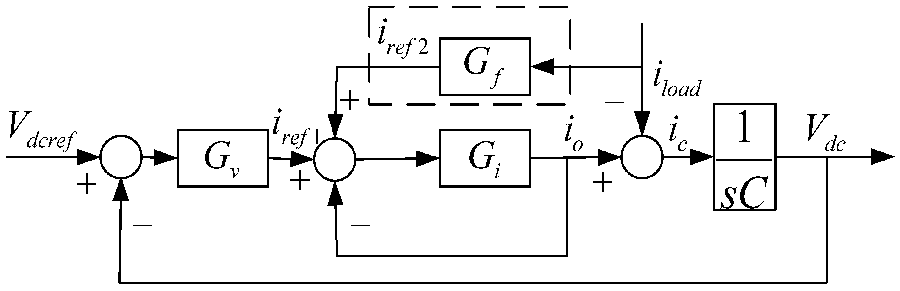
3.2.1. Basic Principle of Current Feedforward Control

In the medium and low voltage small capacity DC distribution network, AC/DC converter usually adopts three-phase six pulse bridge rectifier circuit, and its circuit topology structure is shown in Figure 9.
In Figure 9, e a , e b , e c are three phase voltages of the AC system; i a , i b , i c are the three phase currents of the AC system; v a , v b , v c are three-phase voltage of converter; R s is the equivalent resistance of the AC power grid line; L s is the equivalent inductance of the AC power grid line; C is a capacitor connected on the DC system side to the filter; u d c is the bus voltage of the DC system. l o a d is the load of the DC grid.
The traditional AC/DC grid side converter adopts double closed-loop control strategy of the voltage outer loop and current inner loop, and its control block diagram is shown in Figure 10.
According to Figure 10, the DC bus voltage of the grid side converter can be deduced as follows:
V d c ( s ) = G v ( s ) G i ( s ) G v ( s ) G i ( s ) + G i ( s ) s C + s C V d c r e f ( s ) 1 + G i ( s ) G v ( s ) G i ( s ) + G i ( s ) s C + s C i l o a d ( s )
It can be seen from Equation (25) that the DC bus voltage output by the grid side converter is related to the reference value of the DC bus voltage and the load current. The disturbance of the load current causes the bus voltage V d c to change. However, only when V d c deviates from V d c r e f obviously, the active current setting of the grid side converter can change greatly. In addition, with the delay effect of the PI regulator, so the bus voltage will fluctuate. Therefore, the fluctuation of the bus voltage can be eliminated by adding the current feed-forward control link. The control block diagram is shown in Figure 11.

3.2.2. Terminal Sliding Mode Current Feedforward Control Based on Extended State Observer

In order to solve the problem of the DC bus voltage fluctuation, the extended state observer (ESO) and terminal sliding mode control (TSMC) are used to estimate the load current in real time and feed the forward control.
From the topology of the grid side converter in Figure 9, the following result can be obtained:
C d v d c d t = i o i l o a d
From the control block diagram of the current feedforward in Figure 11, the following result can be obtained:
i r e f 2 = G f ( s ) i l o a d = 1 + G i ( s ) G i ( s ) i l o a d
By using the PI controller in the inner current loop, the following result can be obtained:
G i ( s ) = K ( 1 + 1 s T )
The result of simultaneous Equations (26)–(28) is as follows:
Δ V ¨ d c = 1 C i ˙ o + K C ( K T + T ) ( T i ˙ r e f 2 i l o a d ) K C ( K T + T ) i r e f 2
Order:
{ x = Δ V d c w ( t ) = 1 C i ˙ o + K C ( K T + T ) ( T i ˙ r e f 2 i l o a d ) b = K C ( K T + T ) u ( t ) = i r e f 2
Then, Equation (29) can be expressed as
{ x ˙ 1 = x 2 x ˙ 2 = w ( t ) + b u ( t )
It can be seen from Equation (31) that the system is a second-order system. It is necessary to design the third-order extended state observer of Equation (32) to estimate the state variables x 1 , x 2 in the system and the uncertainties of the model and external disturbances in real time.
{ z ˙ 1 = z 2 k 1 g ( z 1 x ( t ) ) g ( z 1 x ( t ) ) z ˙ 2 = z 3 k 2 g ( z 1 x ( t ) ) g ( z 1 x ( t ) ) + b u ( t ) z ˙ 3 = k 3 g ( z 1 x ( t ) ) g ( z 1 x ( t ) )
where: z 1 , z 2 is the real time estimation of the system state variables x 1 , x 2 by the extended state observer; z 3 is the estimation value of the uncertainty w ( t ) ; the parameter k 1 , k 2 , k 3 are derived according to the parameter dynamic determination method. By selecting appropriate third-order polynomial poles, the eigenvalues of the system compensation matrix are located in the left half complex plane, so as to ensure that the system is stable under bounded disturbances and can quickly reach the stable equilibrium point; b = K / ( C K T + C T ) , it is related to the system. The nonlinear function g ( z ) is selected as
g ( z ) = f a l ( z , α , δ ) = { | z | α s i g n ( z ) , | z | δ z δ 1 α , | z | < δ
where: α = 0.5; δ = 0.01.
According to the basic principle of global fast sliding mode controller, the following parameters are selected:
s 0 = c 1 z 1 + z 2
The fast terminal sliding mode surface is constructed as follows:
s 1 = s ˙ 0 + α s 0 + β s 0 q p
where: p , q are the positive odd numbers, and satisfy 1 < p / q < 2 , thus Equation (36) can be obtained:
u 0 = c 1 z 2 α s 0 β s 0 q p
Finally, the control law of load current is obtained as follows:
u ( t ) = u 0 z 3 b
According to the above analysis, the structure block diagram of terminal sliding mode controller based on extended state observer is shown in Figure 12.

3.2.3. Simulation Analysis

The ESO and terminal sliding mode feedforward control are added to the grid side converter. The output of the PI and the terminal sliding mode control is used as the given value of d-axis current in the current inner loop of grid side converter. At the moment of load disturbance or sudden change of grid voltage amplitude, the given value of the d-axis current is changed in time, so that the current inner loop of grid side converter can control the fast tracking command of the d-axis current. The comparison of the DC bus voltage under the terminal sliding mode control and PI control is shown in Figure 13.
It can be seen from Figure 13 that the extended state observer and terminal sliding mode control have good action characteristics and fast response speed, as the rising speed of the DC bus voltage is very fast at the moment of fault. After shortening the regulation time, the DC bus voltage can be reduced from 3.45 p.u. to 1.17 p.u. at the moment of fault. The fluctuation of the DC bus voltage is greatly reduced. The strategy effectively improves the dynamic response speed of the control system to load disturbance and grid voltage amplitude mutation. Additionally, the anti-load-disturbance performance of the system is greatly improved.

4. Case Simulation Analysis of Zero-Voltage Ride Through Cooperative Control Strategy for Doubly Fed Induction Generator

The grid connected model of the doubly fed wind turbine is built in DIgSILENT (DIgSILENT GmbH, Gomaringen, Germany) simulation software, and the effectiveness of the zero-voltage ride through cooperative control strategy is verified by simulation experiments. A 5 MW doubly fed wind turbine is selected to connect to the 3.3 kV distribution network and output power to the 30 KV grid. Ignoring the change of wind speed, it is considered that the wind speed of the wind turbine remains constant during the fault transient process. Additionally, the initial wind speed of the DFIG is 13.778 m/s. An active crowbar hardware protection circuit is added to the rotor side of the DFIG. Additionally, terminal sliding mode nonlinear robust current feedforward control based on an extended state observer is added to the control strategy of the grid side converter.
In 0.5 s, the three-phase short-circuit fault occurs at the connection point of the DFIG, and the fault is cleared in 0.9 s. The resistance of the active crowbar circuit is 1.5 p.u. The specific simulation results under the cooperative control strategy of zero-voltage ride through for DFIG are as follows.
As can be seen from Figure 14, after the three-phase short-circuit fault occurs, the voltage of the parallel point drops to 0 instantly. Due to the increase in energy on the rotor side of the generator, the mechanical energy of the wind turbine cannot be completely transmitted, which has an impact on the wind turbine system. The rotating angular velocity of the wind turbine increases from 2.036 rad/s to 2.237 rad/s. Then, the wind turbine system makes its own adjustment to reduce the absorption of wind energy to slow down the impact of fault. The utilization coefficient of the wind energy is reduced from 0.387 to 0.344. Additionally, the mechanical power output on the shaft is also reduced from 0.975 p.u. to 0.103 p.u., so as to reduce the system energy.
In the face of a zero-voltage fault, when the cooperative control strategy is adopted, it can be seen from Figure 15 that the rotor voltage firstly decreases from 0.079 p.u. to 0 due to the rotor short connection protection circuit. Additionally, it then recovers to 0.136 p.u. The rotor current decreases to 0.885 kA during the fault period, and then recovers to 2.291 kA. The rotational speed of the DFIG increases from 1.080 p.u. to 1.149 p.u. during the fault period, and then gradually stabilizes. At the moment of three-phase short-circuit fault, the DC bus voltage can be controlled at 1.17 p.u. By adopting the cooperative control strategy, the doubly fed wind turbine realizes zero-voltage ride through.

5. Conclusions

In this paper, concentrating on the most serious case of grid voltage sag fault, namely zero-voltage fault, the fault ride through control strategy of the DFIG is studied. The active crowbar hardware protection circuit is added to the rotor side, and the range of its resistance value and switching strategy are analyzed. The input of the protection circuit can effectively limit the rotor overcurrent, protect the rotor side converter, reduce the impact on the generator set, and play a certain role in the recovery of the active and reactive power of the wind power generation system. However, due to the strong coupling between stator and rotor, when the voltage drops deeply, the rotor side will induce a higher induced electromotive force. When the protection circuit is put into operation, considering the delay effect of the PI regulator, the DC bus voltage will rise briefly. Therefore, the control strategy of grid side converter is improved by adding the extended state observer and terminal sliding mode feedforward control. The control system can immediately follow the change of the load, accelerate the dynamic response of the system, and the DC bus voltage can quickly tend to be stable, which plays an obvious role in protecting the power devices in the system. Cooperative control technology improves the situation and shows that single strategy is only suitable for low voltage ride through of the DFIG. The proposed method can realize the zero-voltage ride through capability of the doubly fed wind turbine, thereby ensuring and maintaining the safe and stable operation of the wind power system.

Author Contributions

S.W. put forward the idea; Z.K. gave the guidance; K.Q. performed the modeling and simulation and wrote the manuscript. All authors have read and agreed to the published version of the manuscript.

Funding

This research was funded by the science and technology project of China Electric Power Research Institute, with the approval number of EPRI4130-191881.

Institutional Review Board Statement

Not applicable.

Data Availability Statement

Not applicable.

Conflicts of Interest

The authors declare no conflict of interest.

References

  1. Jiang, Z.; Liu, Y. Low-voltage ride-through remote testing method for offshore wind turbines. IEEE Trans. Instrum. Meas. 2020, 69, 2905–2913. [Google Scholar] [CrossRef]
  2. Wen, G.; Chen, Y.; Zhong, Z.; Kang, Y. Dynamic voltage and current assignment strategies of nine-switch-converter-based DFIG wind power system for low-voltage ride-through (LVRT) under symmetrical grid voltage dip. IEEE Trans. Ind. Appl. 2016, 52, 3422–3434. [Google Scholar] [CrossRef]
  3. Abad, G.; Rodríguez, M.A.; Poza, J.; Canales, J.M. Direct torque control for doubly fed induction machine-based wind turbines under voltage dips and without crowbar protection. IEEE Trans. Energy Convers. 2010, 25, 586–588. [Google Scholar] [CrossRef]
  4. Wei, Q.; Wu, B.; Xu, D.; Zargari, N.R. A new configuration using PWM current source converters in low-voltage turbine-based wind energy conversion systems. IEEE J. Emerg. Sel. Top. Power Electron. 2018, 6, 919–929. [Google Scholar] [CrossRef]
  5. Tsili, M.; Papathanassiou, S. A review of grid code technical requirements for wind farms. IET Renew. Power Gener. 2009, 3, 308–332. [Google Scholar] [CrossRef]
  6. Shao, H.; Cai, X.; Li, Z. Stability enhancement and direct speed control of the DFIG inertia emulation control strategy. IEEE Access 2019, 7, 120089–120105. [Google Scholar] [CrossRef]
  7. Zeng, C. Research on Low Voltage Ride through of Doubly Fed Wind Turbine Based on PSCAD/EMTDC. Master’s Thesis, Kunming University of Science and Technology, Kunming, China, 2014. [Google Scholar]
  8. Abbey, C.; Li, W.; Owatta, L.; Joos, G. Power electronic converter control techniques for improved low voltage ride through performance in WTGs. In Proceedings of the IEEE Power Electronics Specialists Conference, Jeju, Korea, 18–22 June 2006. [Google Scholar]
  9. Huang, Q.; Sun, M.; Zou, X.; Tong, L.; Xiong, W.; Chen, J. A reverse current tracking based LVRT strategy for doubly fed induction generator (DFIG). In Proceedings of the IECON 2013—39th Annual Conference of the IEEE Industrial Electronics Society, Vienna, Australia, 10–13 November 2013. [Google Scholar]
  10. Jiang, H.; Zhang, C.; Zhou, T.; Zhang, Y.; Zhang, F. An adaptive control strategy of crowbar for the low voltage ride-through capability enhancement of the DFIG. Energy Procedia 2019, 158, 601–606. [Google Scholar] [CrossRef]
  11. Dolu, M. Crowbar hardware design enhancement for fault ride through capability in doubly fed induction generator-based wind turbines. ISA Trans. 2020, 104, 321–328. [Google Scholar]
  12. Gholizadeh, M.; Tohidi, S.; Oraee, A.; Oraee, H. Appropriate crowbar protection for improvement of brushless DFIG LVRT during asymmetrical voltage dips. Int. J. Electr. Power Energy Syst. 2018, 95, 1–10. [Google Scholar] [CrossRef]
  13. Wang, M.; Xu, W.; Jia, H.; Yu, X. A new method for DFIG fault ride through using resistance and capacity crowbar circuit. In Proceedings of the 2013 IEEE International Conference on Industrial Technology (ICIT), Cape Town, South Africa, 25–28 February 2013. [Google Scholar]
  14. Naderi, S.B.; Negnevitsky, M.; Jalilian, A.; Tarafdar, M.; Muttaqi, K.M. Optimum resistive type fault current limiter: An efficient solution to achieve maximum fault ride-through capability of fixed-speed wind turbines during symmetrical and asymmetrical grid faults. IEEE Trans. Ind. Appl. 2017, 53, 538–548. [Google Scholar] [CrossRef]
  15. Firouzi, M.; Gharehpetian, G.B. Improving fault ride-through capability of fixed-speed wind turbine by using bridge-type fault current limiter. IEEE Trans. Energy Convers. 2013, 28, 361–369. [Google Scholar] [CrossRef]
  16. Fereidouni, A.R.; Vahidi, B.; Hosseini, T. The impact of solid state fault current limiter on power network with wind-turbine power generation. IEEE Trans. Smart Grid 2013, 4, 1188–1196. [Google Scholar] [CrossRef]
  17. Guo, W. Development of a 1-mva/1-mj superconducting fault current limiter–magnetic energy storage system for LVRT capability enhancement and wind power smoothing. IEEE Trans. Appl. Supercond. 2018, 28, 1–5. [Google Scholar] [CrossRef]
  18. Yang, L.; Xu, Z.; Ostergaard, J.; Dong, Z.Y.; Wong, K.P. Advanced control strategy of the DFIG wind turbines for power system fault ride through. IEEE Trans. Power Syst. 2012, 27, 713–722. [Google Scholar] [CrossRef] [Green Version]
  19. Bourdoulis, M.K.; Alexandridis, A.T. Dynamic analysis of PI controllers applied on AC/DC grid-side converters used in wind power generation. In Proceedings of the IET Conference on Renewable Power Generation, Edinburgh, UK, 6–8 September 2011. [Google Scholar]
  20. Lyu, M.; Hong, L.; Xu, Q.; Liao, W.; Wu, G.; Huang, S.; Peng, Y. Analysis and design of PI plus repetitive control for grid-side converters of direct-drive wind power systems considering the effect of hardware sampling circuits. IEEE Access 2020, 8, 87947–87959. [Google Scholar] [CrossRef]
  21. Firouzi, M.; Nasiri, M.; Mobayen, S.; Gharehpetian, G. Sliding mode controller-based BFCL for fault ride-through performance enhancement of the DFIG-based wind turbines. Complexity 2020, 2020. [Google Scholar] [CrossRef]
  22. Shanoob, M.; Iqbal, K. State feedback sliding mode control law design for grid-connected wind turbine model. In Proceedings of the 2019 IEEE 7th International Conference on Smart Energy Grid Engineering (SEGE), Oshawa, ON, Canada, 12–14 August 2019. [Google Scholar]
  23. Colombo, L.; Corradini, M.; Ippoliti, G.; Orlando, G. Pitch angle control of a wind turbine operating above the rated wind speed: A sliding mode control approach. ISA Trans. 2020, 96, 95–102. [Google Scholar] [CrossRef] [PubMed]
  24. Iqbal, A.; Deng, Y.; Adeel, S.; Muhammad, A.; Kashif, M. Efficacious pitch angle control of variable-speed wind turbine using fuzzy based predictive controller. Energy Rep. 2020, 6, 423–427. [Google Scholar] [CrossRef]
  25. Zhao, H. The research of zero voltage ride through strategy of the DFIG. In Proceedings of the IET International Conference on Renewable Power Generation (RPG 2016), London, UK, 21–23 September 2016. [Google Scholar]
  26. Zhao, H.; Tang, H.; Zhang, W.; Wen, W.L. Transient characteristics research and integrated control strategy of the DFIG for zero voltage ride through. Power Syst. Technol. 2016, 40, 1422–1430. [Google Scholar]
  27. Tang, H.; Chang, Y.; Chi, Y.; Wang, B.; Li, Y.; Hu, J. Analysis and control of doubly fed induction generator for zero voltage ride through. In Proceedings of the 19th International Conference on Electrical Machines and Systems (ICEMS), Chiba, Japan, 13–16 November 2016. [Google Scholar]
  28. Cai, E.; Yan, Y.; Dong, L.; Liao, X. A control scheme with the variable-speed pitch system for wind turbines during a zero-voltage ride through. Energies 2020, 13, 3344. [Google Scholar] [CrossRef]
Figure 1. Equivalent physical model of the doubly fed induction generator.
Energies 14 02287 g001
Figure 2. Rotor current curve of the doubly fed induction generator (DFIG) under three-phase short-circuit fault.
Energies 14 02287 g002
Figure 3. DC bus voltage curve under three-phase short-circuit fault.
Energies 14 02287 g003
Figure 4. Schematic of active crowbar protection circuit.
Energies 14 02287 g004
Figure 5. Control flow chart of active crowbar protection.
Energies 14 02287 g005
Figure 6. Comparison of the rotor current whether to add active crowbar protection circuit.
Energies 14 02287 g006
Figure 7. Action signal curve of active crowbar protection circuit.
Energies 14 02287 g007
Figure 8. DC bus voltage curve under PI control.
Energies 14 02287 g008
Figure 9. Topology structure of AC/DC converter.
Energies 14 02287 g009
Figure 10. Double closed-loop control block diagram of AC/DC converter.
Energies 14 02287 g010
Figure 11. Double closed-loop control block diagram based on current feedforward.
Energies 14 02287 g011
Figure 12. The structure block diagram of terminal sliding mode controller based on extended state observer.
Energies 14 02287 g012
Figure 13. Comparison of the DC bus voltage under terminal sliding mode control and PI control.
Energies 14 02287 g013
Figure 14. Wind turbine system. (a) Voltage drop curve of parallel point of the doubly fed wind turbine; (b) the rotating angular velocity of the wind turbine; (c) the utilization coefficient of wind energy; (d) mechanical power on the shaft.
Energies 14 02287 g014
Figure 15. Double-fed power generation system. (a) Rotor voltage; (b) rotor current; (c) rotational speed; (d) DC bus voltage.
Energies 14 02287 g015
Publisher’s Note: MDPI stays neutral with regard to jurisdictional claims in published maps and institutional affiliations.

