
Investigation of Thermal-Flow Characteristics of Pipes with Helical Micro-Fins of Variable Height

 , , , and
Abstract
:1. Introduction
2. Materials and Methods
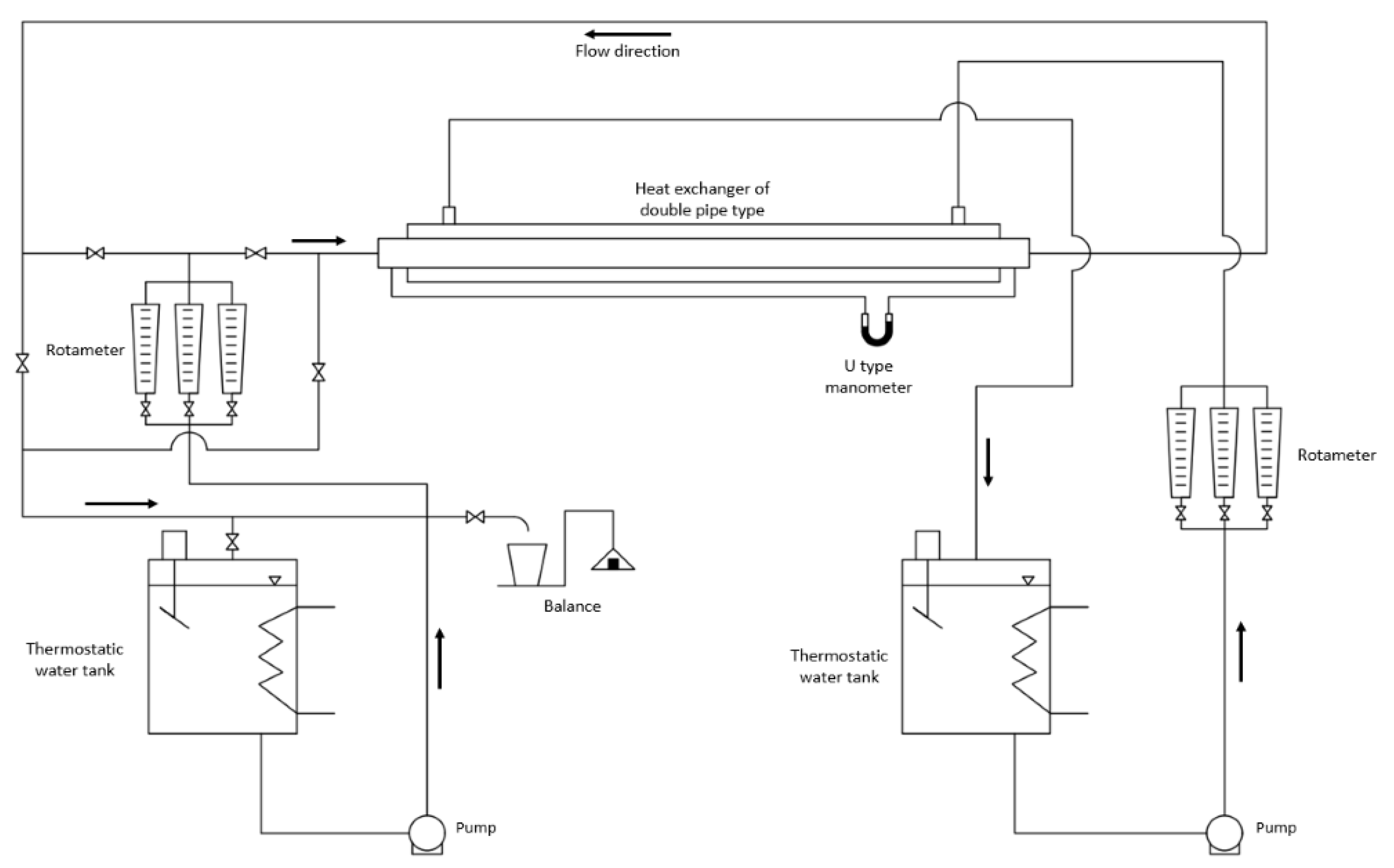
2.1. Experimental Stand
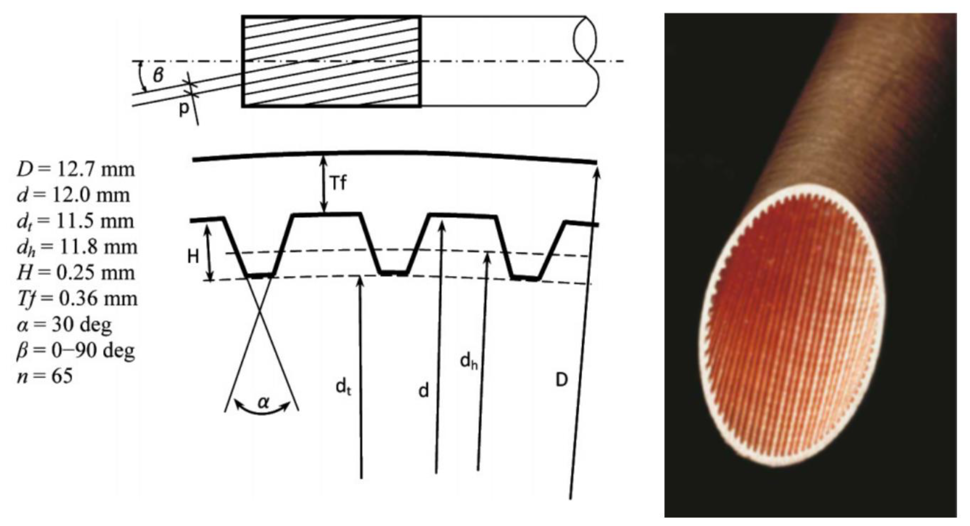
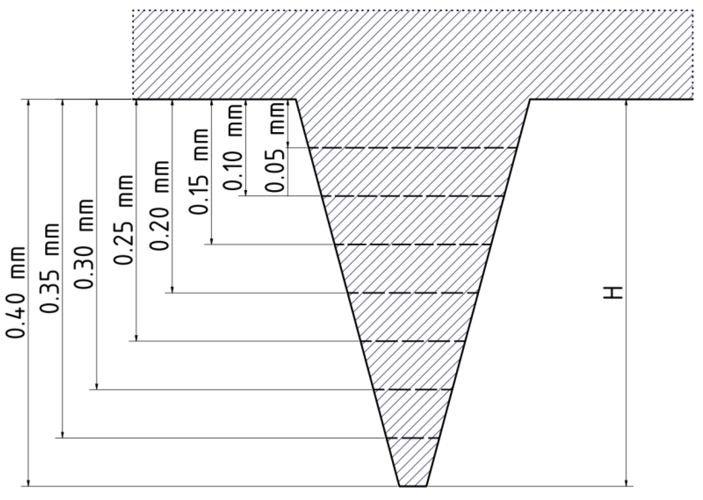
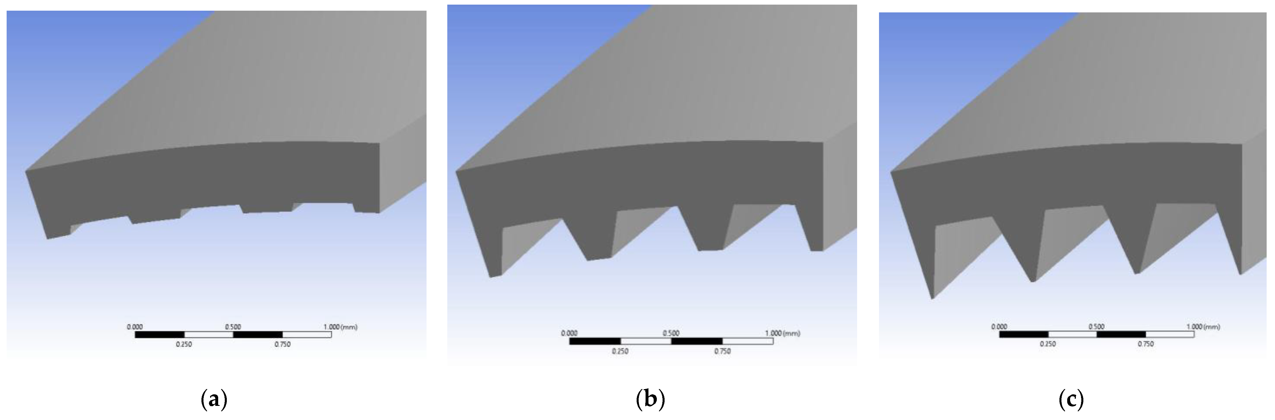
2.2. Geometrical Model
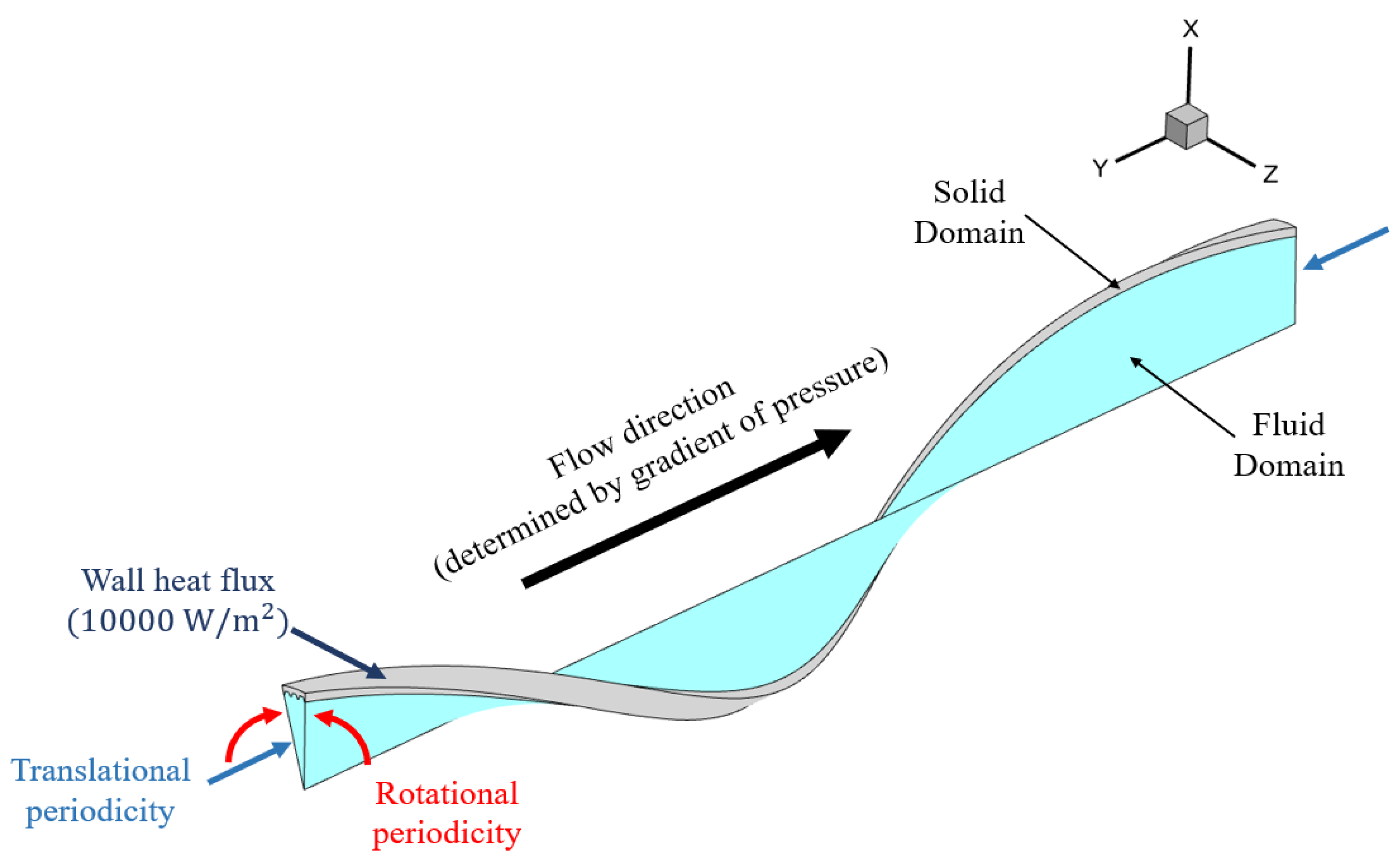
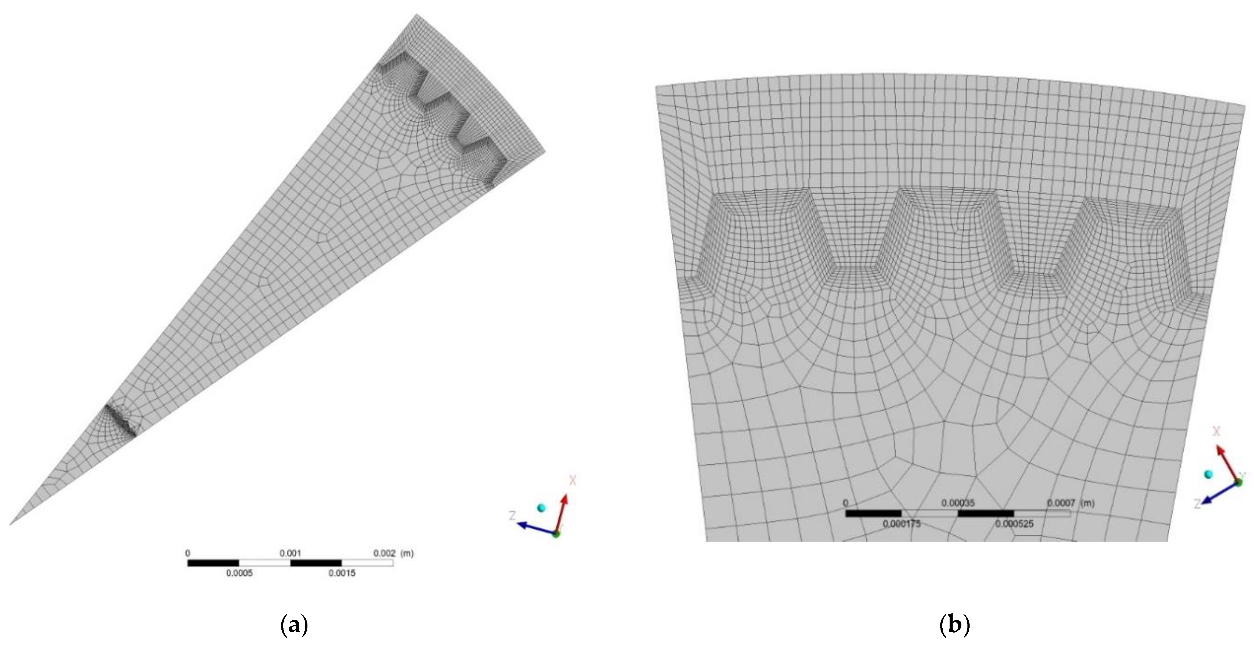
2.3. Numerical Model
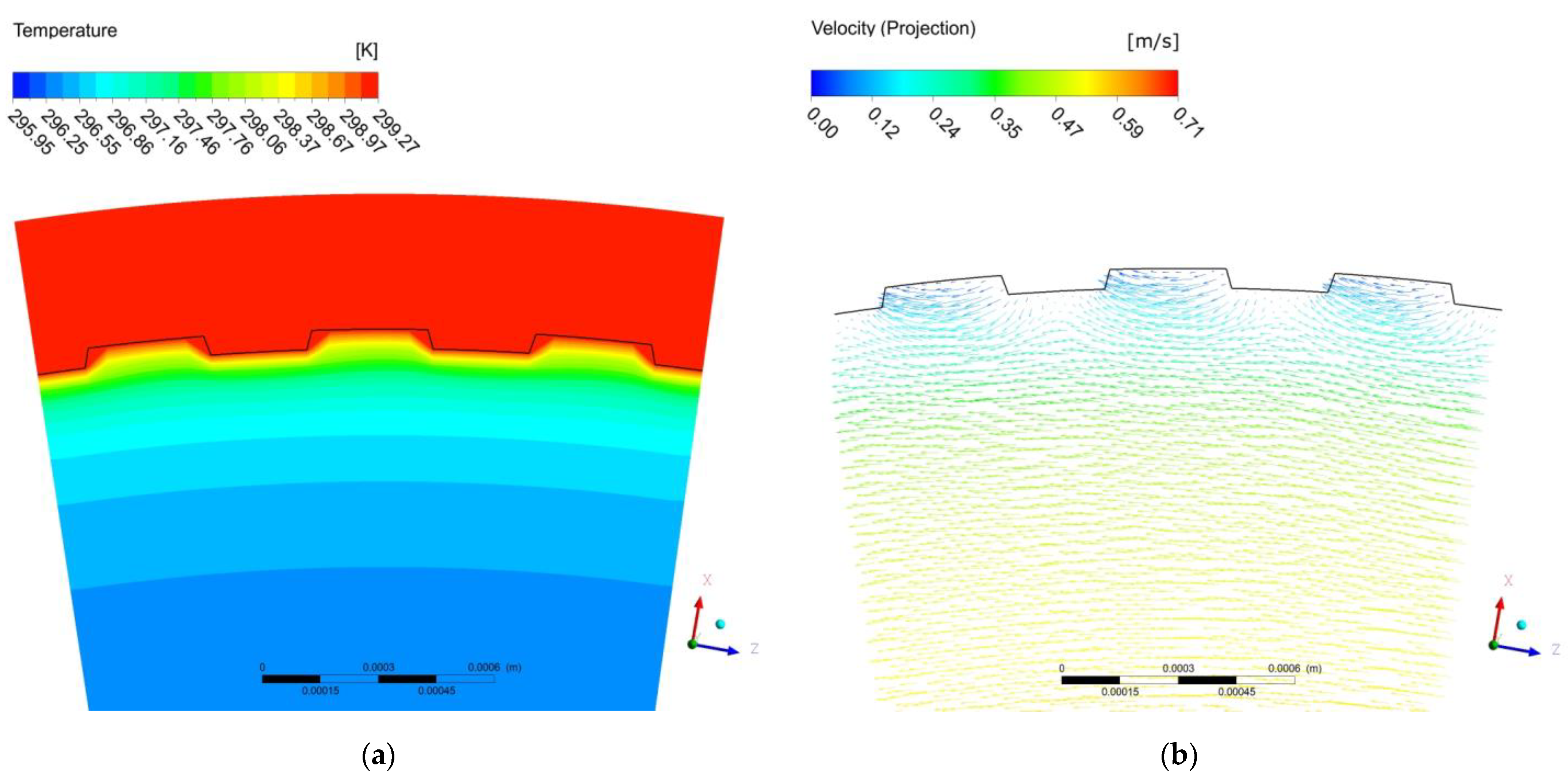
3. Results
3.1. Data Processing
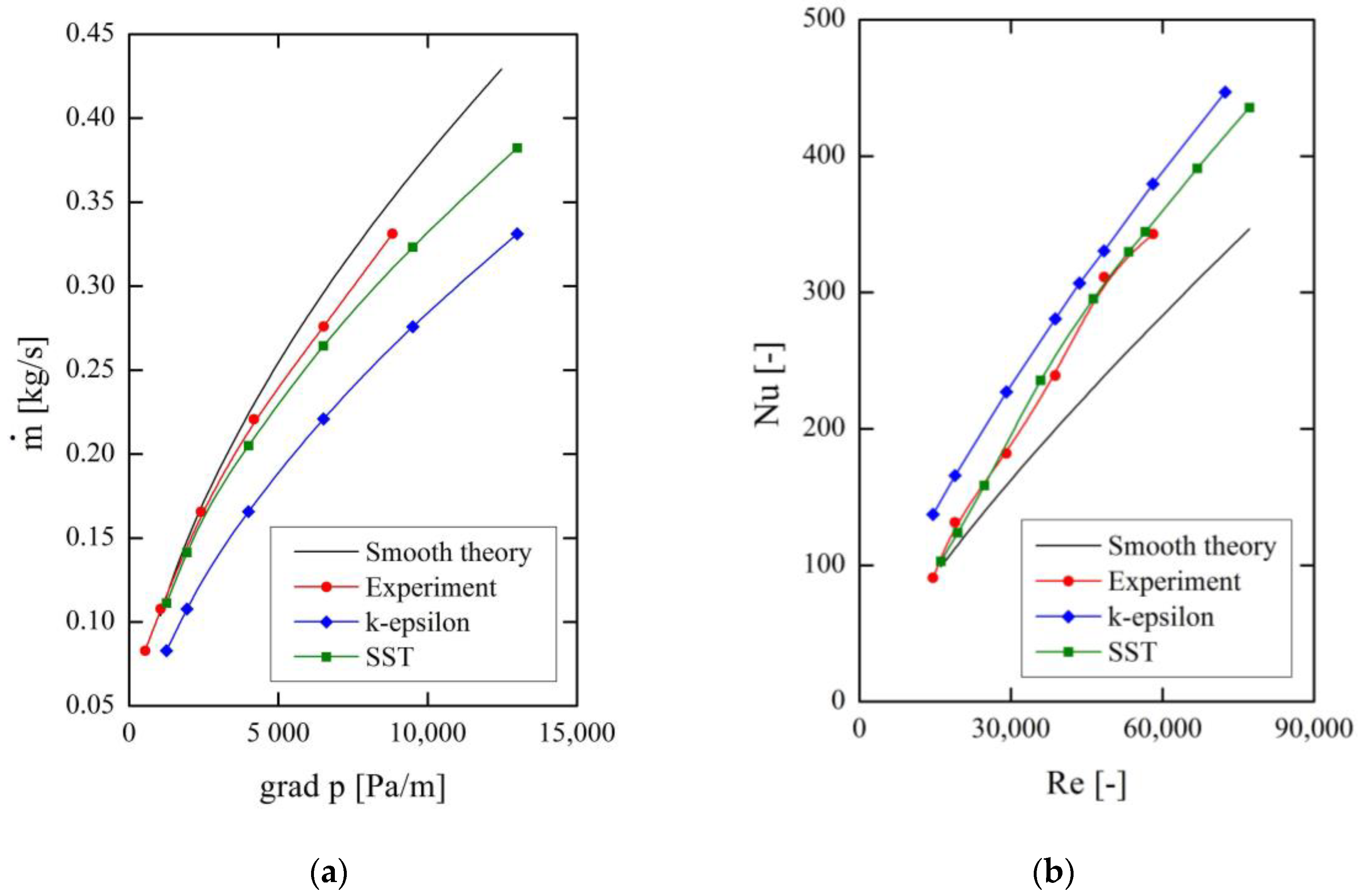
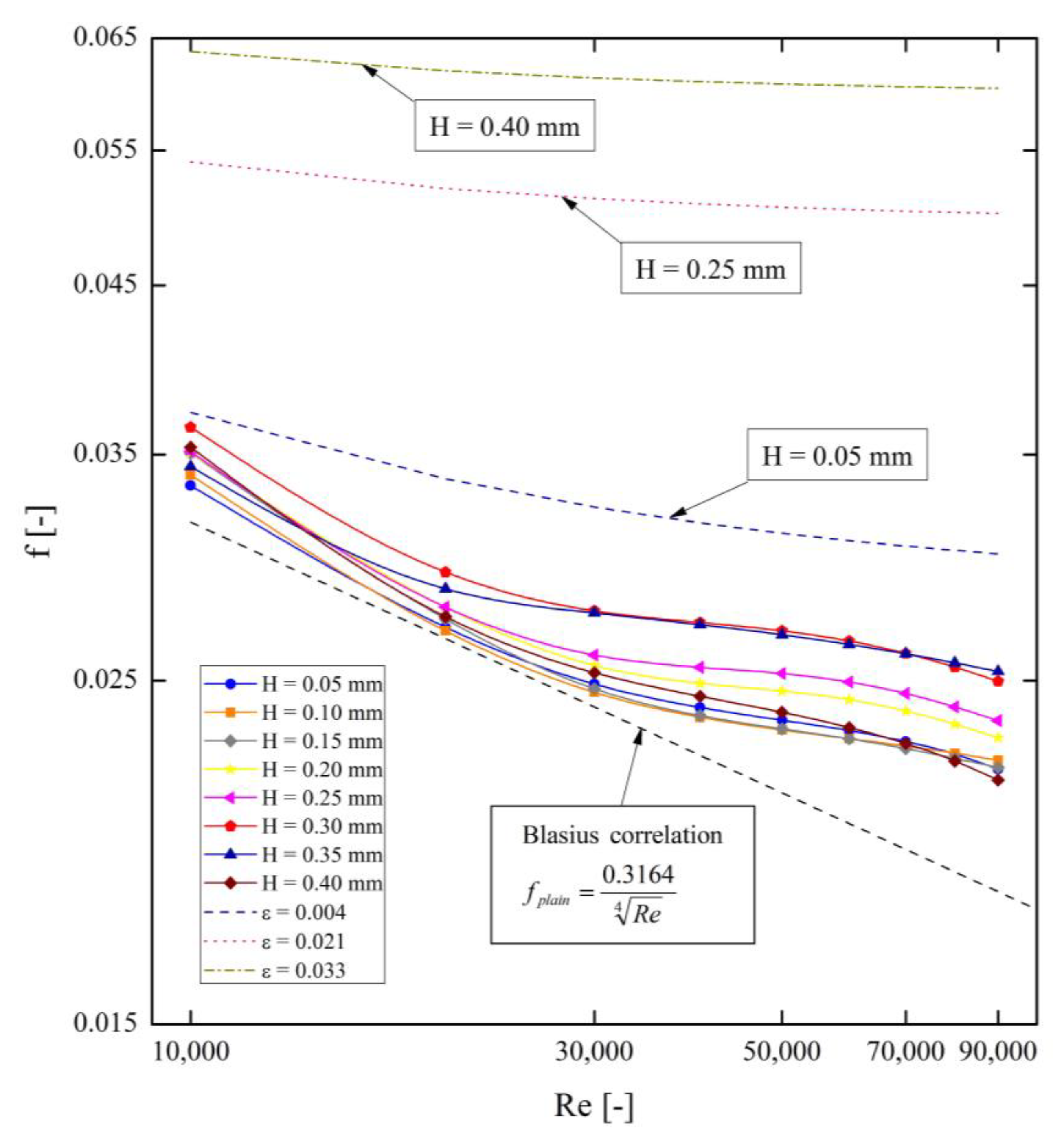
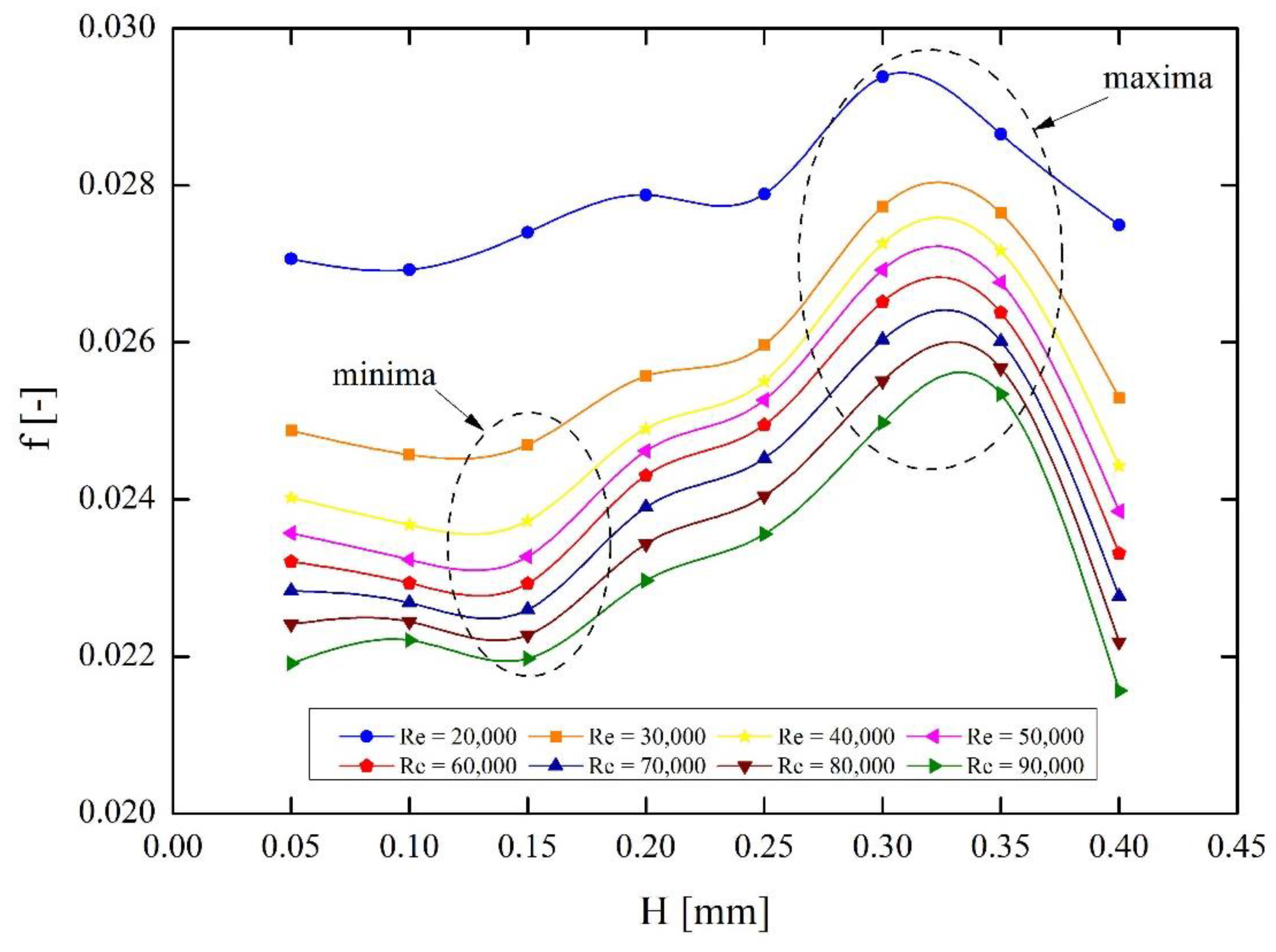
3.2. Friction Factor
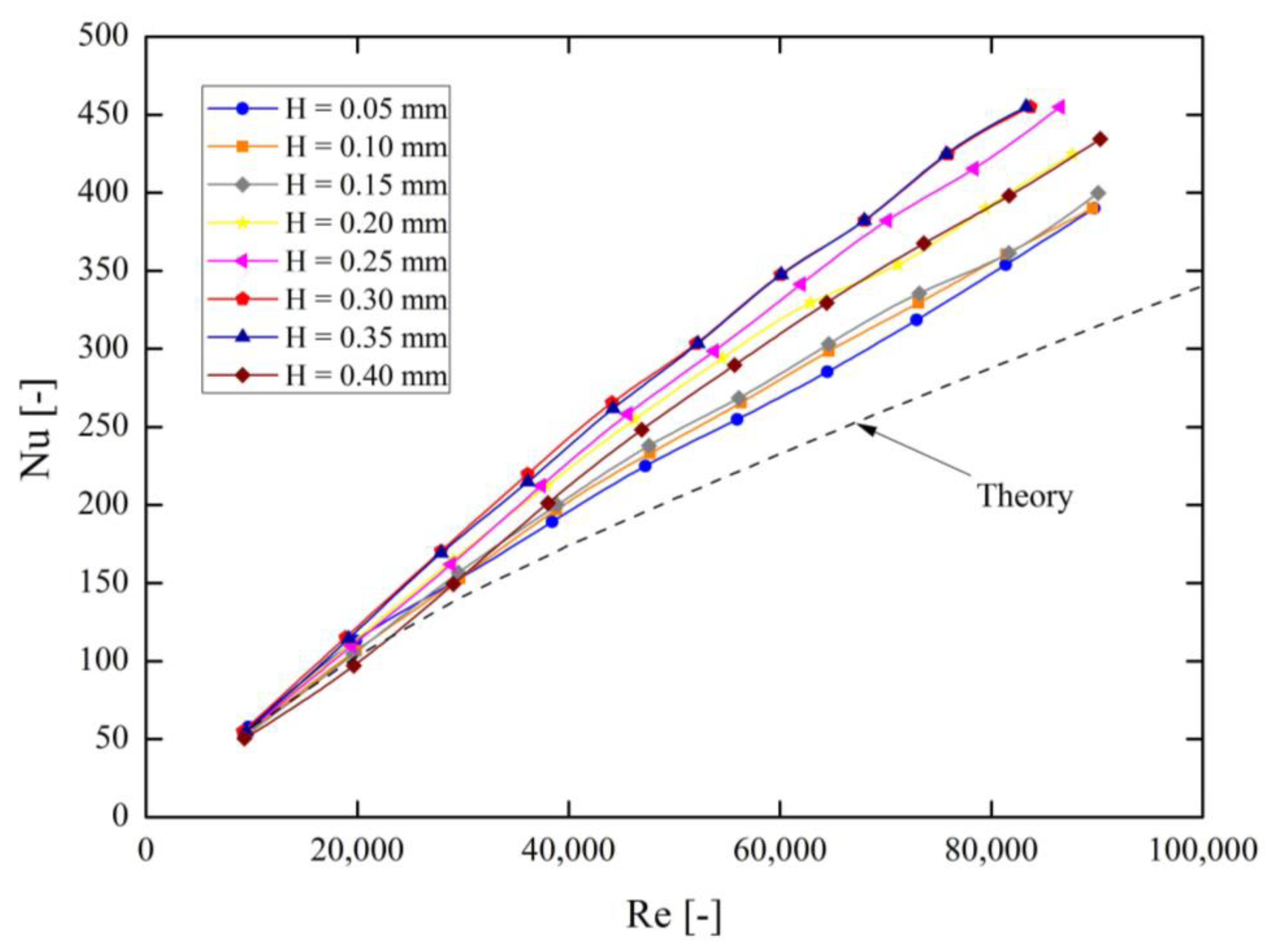
3.3. Heat Transfer
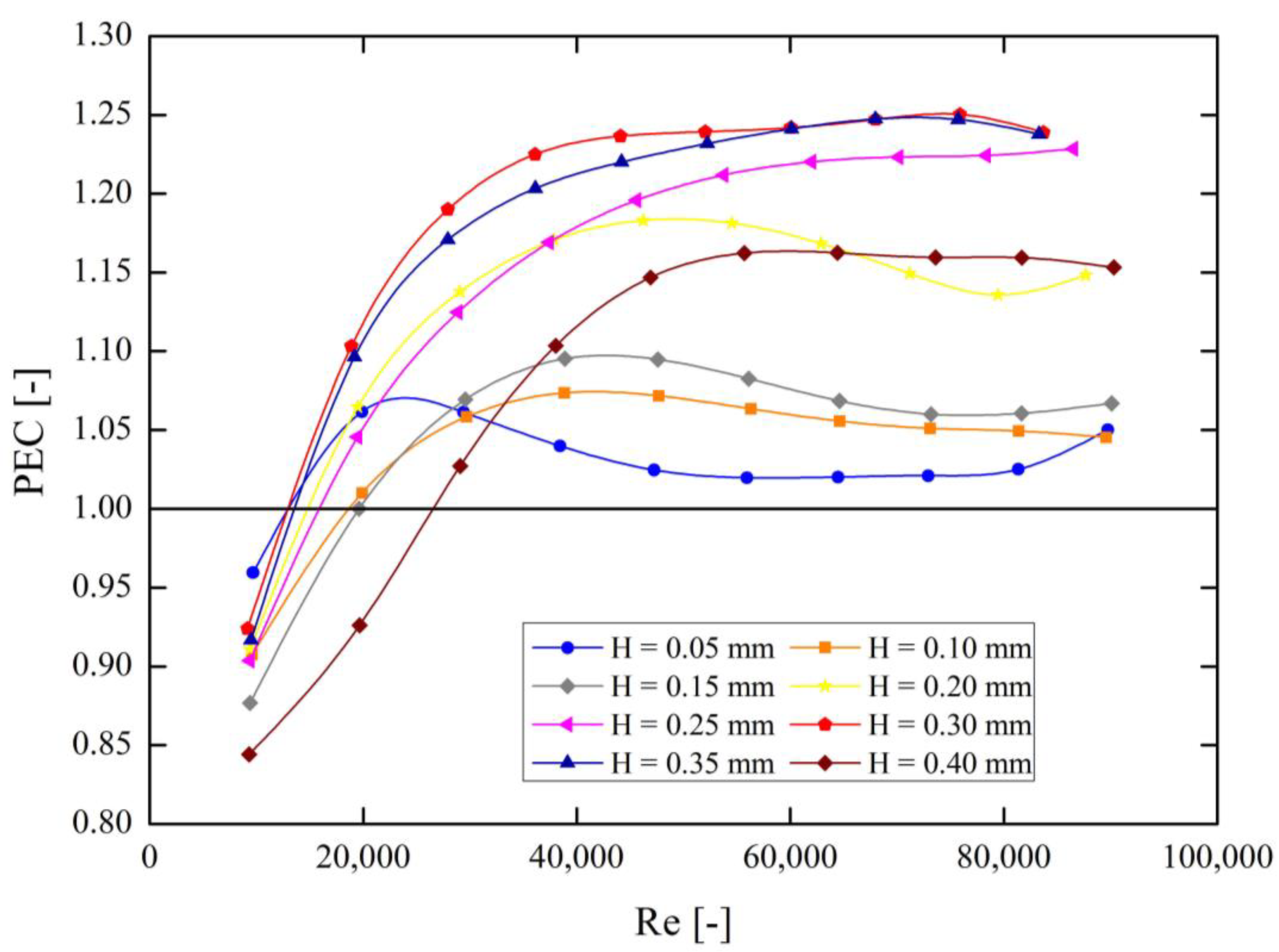
3.4. PEC (Performance Evaluation Criteria)
4. Discussion
5. Conclusions
- A numerical model of the tested pipes was built and verified with the experimental data.
- The mathematical correlations describing the nature of changes in the friction factor and the Nusselt number as a function of the Reynolds number were determined for the examined micro-fins heights.
- Using the PEC (Performance Evaluation Criteria) method of assessing the thermal efficiency of flow channels, the highest values were observed for micro-fins with the height of H = 0.30 mm and H = 0.35 mm.
- The theoretical formulas for the friction factor for rough pipes (Moody’s diagram) were not compatible with the obtained numerical results for the same relative roughness, but with a regular shape.
- For Reynolds numbers below 20,000, the use of the investigated type of pipe micro-finning is unjustified in terms of heat transfer efficiency.
Author Contributions
Funding
Institutional Review Board Statement
Informed Consent Statement
Data Availability Statement
Acknowledgments
Conflicts of Interest
Nomenclature
| Awall | exterior area of the pipe [m2] |
| d | diameter [mm] |
| f | friction factor [-] |
| fplain | friction factor for plain tube [-] |
| GCIfine | fine-grid convergence index [%] |
| h | heat transfer coefficient [W/m2K] |
| H | height of fin [mm] |
| k | thermal conductivity [W/mK] |
| L | length of the pipe [m] |
| Nu | Nusselt number [-] |
| Nuplain | Nusselt number for plain tube [-] |
| PEC | performance evaluation criteria [-] |
| ∆p | pressure drop [Pa] |
| Pr | Prandtl number [-] |
| Qvol | volumetric heat flux [W/m3] |
| q | wall heat flux [W/m2] |
| Re | Reynolds number [-] |
| Twall | average temperature in pipe [K] |
| Tbulk | minimal temperature in water [K] |
| uav | average velocity [m/s] |
| Vwater | volume of water domain [m3] |
| α | micro-fin angle [°] |
| β | helical angle of micro-fin [°] |
| ρ | density [kg/m3] |
| ε | relative roughness [-] |
References
- Wijayanta, A.T.; Pranowo; Mirmanto; Kristiawan, B.; Aziz, M. Internal flow in an enhanced tube having square-cut twisted tape insert. Energies 2019, 12, 306. [Google Scholar] [CrossRef] [Green Version]
- Wijayanta, A.T.; Aziz, M.; Kariya, K.; Miyara, A. Numerical study of heat transfer enhancement of internal flow using double-sided delta-winglet tape insert. Energies 2018, 11, 3170. [Google Scholar] [CrossRef] [Green Version]
- Jasiński, P.B. Numerical study of the thermo-hydraulic characteristics in a circular tube with ball turbulators. Part 1: PIV experiments and a pressure drop. Int. J. Heat Mass Transf. 2014, 74, 48–59. [Google Scholar] [CrossRef]
- Jasiński, P.B. Numerical study of the thermo-hydraulic characteristics in a circular tube with ball turbulators. Part 2: Heat transfer. Int. J. Heat Mass Transf. 2014, 74, 473–483. [Google Scholar] [CrossRef]
- Jasiński, P.B. Numerical study of thermo-hydraulic characteristics in a circular tube with ball turbulators. Part 3: Thermal performance analysis. Int. J. Heat Mass Transf. 2017, 107, 1138–1147. [Google Scholar] [CrossRef]
- Arjmandi, H.; Amiri, P.; Pour, M.S. Geometric optimization of a double pipe heat exchanger with combined vortex generator and twisted tape: A CFD and response surface methodology (RSM) study. Therm. Sci. Eng. Prog. 2020, 18. [Google Scholar] [CrossRef]
- Patil, M.S.; Seo, J.-H.; Kang, S.-J.; Lee, M.-Y. Review on synthesis, thermo-physical property, and heat transfer mechanism of nanofluids. Energies 2016, 9, 840. [Google Scholar] [CrossRef] [Green Version]
- Shajahan, M.I.; Michael, J.J.; Arulprakasajothi, M.; Suresh, S.; Nasr, E.A.; Hussein, H.M.A. Effect of Conical Strip Inserts and ZrO 2 / DI-Water Nanofluid on Heat Transfer Augmentation: An experimental study. Energies 2020, 13, 4554. [Google Scholar] [CrossRef]
- Kristiawan, B.; Wijayanta, A.T.; Enoki, K.; Miyazaki, T.; Aziz, M. Heat transfer enhancement of TiO2/water nanofluids flowing inside a square minichannel with a microfin structure: A numerical investigation. Energies 2019, 12, 3041. [Google Scholar] [CrossRef] [Green Version]
- Asirvatham, L.G.; Vishal, N.; Gangatharan, S.K.; Lal, D.M. Experimental Study on Forced Convective Heat Transfer with Low Volume Fraction of CuO/Water Nanofluid. Energies 2009, 2, 97–119. [Google Scholar] [CrossRef]
- Mann, G.W.; Eckels, S. Multi-objective heat transfer optimization of 2D helical micro-fins using NSGA-II. Int. J. Heat Mass Transf. 2019, 132, 1250–1261. [Google Scholar] [CrossRef]
- Ji, W.-T.; Zhang, D.-C.; He, Y.-L.; Tao, W.-Q. Prediction of fully developed turbulent heat transfer of internal helically ribbed tubes? An extension of Gnielinski equation. Int. J. Heat Mass Transf. 2012, 55, 1375–1384. [Google Scholar] [CrossRef]
- Li, P.; Campbell, M.; Zhang, N.; Eckels, S.J. Relationship between turbulent structures and heat transfer in microfin enhanced surfaces using large eddy simulations and particle image velocimetry. Int. J. Heat Mass Transf. 2019, 136, 1282–1298. [Google Scholar] [CrossRef]
- He, G.-D.; Fang, X.-M.; Xu, T.; Zhang, Z.-G.; Gao, X.-N. Forced convective heat transfer and flow characteristics of ionic liquid as a new heat transfer fluid inside smooth and microfin tubes. Int. J. Heat Mass Transf. 2015, 91, 170–177. [Google Scholar] [CrossRef]
- Brognaux, L.; Webb, R.L.; Chamra, L.M.; Chung, B.Y. Single-phase heat transfer in micro-fin tubes. Int. J. Heat Mass Transf. 1997, 40, 4345–4357. [Google Scholar] [CrossRef]
- Jasiński, P. Numerical optimization of flow-heat ducts with helical micro-fins, using entropy generation minimization (EGM) method. In Recently Advances in Fluid Mechanics and Heat & Mass Transfer, Proceedings of the 9th IASME/WSEAS International Conference on Fluid Mechanics and Aerodynamic Engineering FMA’11, Proceedings of the 9th IASME/WSEAS International Conference on HTE’11, Florence, Italy, 23–25 August 2011; WSEAS: Athens, Greece, 2011; pp. 47–54. [Google Scholar]
- Tang, W.; Li, W. Frictional pressure drop during flow boiling in micro-fin tubes: A new general correlation. Int. J. Heat Mass Transf. 2020, 159, 120049. [Google Scholar] [CrossRef]
- Jensen, M.K.; Vlakancic, A. Technical Note Experimental investigation of turbulent heat transfer and fluid flow in internally finned tubes. Int. J. Heat Mass Transf. 1999, 42, 1343–1351. [Google Scholar] [CrossRef]
- Dastmalchi, M.; Sheikhzadeh, G.A.; Arefmanesh, A. Optimization of micro-finned tubes in double pipe heat exchangers using particle swarm algorithm. Appl. Therm. Eng. 2017, 119, 1–9. [Google Scholar] [CrossRef]
- Dastmalchi, M.; Arefmanesh, A.; Sheikhzadeh, G. Numerical investigation of heat transfer and pressure drop of heat transfer oil in smooth and micro-finned tubes. Int. J. Therm. Sci. 2017, 121, 294–304. [Google Scholar] [CrossRef]
- Filho, E.P.B.; Jabardo, J.M.S. Experimental study of the thermal hydraulic performance of sub-cooled refrigerants flowing in smooth, micro-fin and herringbone tubes. Appl. Therm. Eng. 2014, 62, 461–469. [Google Scholar] [CrossRef]
- Raj, R.; Lakshman, N.S.; Mukkamala, Y. Single phase flow heat transfer and pressure drop measurements in doubly enhanced tubes. Int. J. Therm. Sci. 2015, 88, 215–227. [Google Scholar] [CrossRef]
- Zawadzki, A.; Plocek, M.; Kapusta, T.; Kasieczka, W. Heat transfer and friction factor characteristics of single-phase flow through a circular, internally micro-finned, horizontal tube fitted with twisted tape inserts—experimental investigations. In Proceedings of the XL Refrigeration Days, Poznań, Poland, 15–17 October 2008; pp. 115–124. (In Polish). [Google Scholar]
- Jasiński, P. Numerical Study of Friction Factor and Heat Transfer Characteristics for Single-Phase Turbulent Flow in Tubes with Helical Micro-Fins. Arch. Mech. Eng. 2012, 59, 469–485. [Google Scholar] [CrossRef] [Green Version]
- Sobczak, K.; Obidowski, D.; Reorowicz, P.; Marchewka, E. Numerical investigations of the savonius turbine with deformableblades. Energies 2020, 13, 3717. [Google Scholar] [CrossRef]
- Obidowski, D.; Stajuda, M.; Sobczak, K. Efficient Multi-Objective CFD-Based Optimization Method for a Scroll Distributor. Energies 2021, 14, 377. [Google Scholar] [CrossRef]
- Fodemski, T.; Górecki, G.; Jasiński, P. Corrugated channels heat transfer efficiency Analysis based on velocity fields resulting from computer simulation and PIV Measurements. In Proceedings of the 8th International Conference on Heat Transfer, Fluid Mechanics and Thermodynamics, HEFAT, Pointe Aux Piments, Mauritius, 11–13 July 2011. [Google Scholar]
- Li, X.-W.; Meng, J.-A.; Guo, Z.-Y. Turbulent flow and heat transfer in discrete double inclined ribs tube. Int. J. Heat Mass Transf. 2009, 52, 962–970. [Google Scholar] [CrossRef]
- Di Piazza, I.; Ciofalo, M. Numerical prediction of turbulent flow and heat transfer in helically coiled pipes. Int. J. Therm. Sci. 2010, 49, 653–663. [Google Scholar] [CrossRef]
- Eiamsa-Ard, S.; Wongcharee, K.; Sripattanapipat, S. 3-D Numerical simulation of swirling flow and convective heat transfer in a circular tube induced by means of loose-fit twisted tapes. Int. Commun. Heat Mass Transf. 2009, 36, 947–955. [Google Scholar] [CrossRef]
- Manual ANSYS-CFX, Release 2020 R2. Available online: http://www.ansys.com (accessed on 15 July 2020).
- Celik, I.B.; Ghia, U.; Roache, P.J.; Freitas, C.J.; Coleman, H.; Raad, P.E. Procedure for estimation and reporting of uncertainty due to discretization in CFD applications. J. Fluids Eng. Trans. ASME 2008, 130, 78001–78004. [Google Scholar] [CrossRef] [Green Version]
- Bejan, A. Convection Heat Transfer, 4th ed.; John Wiley & Sons, Inc.: Hoboken, NJ, USA, 2013. [Google Scholar] [CrossRef]
- Holman, J.P. Heat Transfer, 10th ed.; McGraw-Hill, Inc.: New York, NY, USA, 2010. [Google Scholar]
- Swamee, P.K.; Jain, A.K. Explicit Equations for Pipe-Flow Problems. J. Hydraul. Div. 1976, 102, 657–664. [Google Scholar] [CrossRef]
- Moody, L.F. Friction Factors for Pipe Flow. Trans. Am. Soc. Mech. Eng. 1944, 66, 671–681. [Google Scholar]
- Wang, C.C.; Chiou, C.B.; Lu, D.C. Single-phase heat transfer and flow friction correlations for microfin tubes. Int. J. Heat Fluid Flow 1996, 17, 500–506. [Google Scholar] [CrossRef] [Green Version]

| Legend Name | Type | Parameter | Operating Range |
|---|---|---|---|
| Balance | ZAO Gdansk—WT 1002 | Weight [g] | 10–1000 g |
| Thermostatic water tank | MLW—U10 | Temperature [°C] | 20–90 °C |
| Rotameter | Yokogawa—310142/002 | Flow [l/h] | 0–25 L/h |
| Pump | Lowara—2HMS4T/A | Flow rate [l/min] | 20–70 L/min |
| U type manometer | Metalchem—MUR 1200 | Pressure [Pa] | 782.62–11,739.25 Pa |
| H [mm] | 0.05 | 0.10 | 0.15 | 0.20 | 0.25 | 0.30 | 0.35 | 0.40 |
|---|---|---|---|---|---|---|---|---|
| ε [-] | 0.004 | 0.008 | 0.013 | 0.017 | 0.021 | 0.025 | 0.029 | 0.033 |
| Boundary Condition | Description | Parameter | Value/Type |
|---|---|---|---|
| Fluid Domain | Water | Temperature | 298 K |
| Reference pressure | 1 atm | ||
| Turbulence | SST | ||
| Subdomain | Subdomain was set in domain of water. The gradient of pressure determined the flow in Y component. | Gradient of pressure | 440–24,779 Pa |
| Volumetric heat flux | W | ||
| Solid Domain | Copper | Temperature | 298 K |
| Wall | Boundary condition set on exterior area of pipe in the form of constant heat flux | Heat flux | 10,000 |
| Translational periodicity | Translational periodicity set on the inlet and outlet areas of fluid and solid domain. | - | - |
| Rotational periodicity | Rotational periodicity set on the both sides of fluid and solid domain. As the rotation axis, Global Y was set. | - | - |
| H = 0.05 | H = 0.10 | H = 0.15 | H = 0.20 | H = 0.25 | H = 0.30 | H = 0.35 | H = 0.40 | |
|---|---|---|---|---|---|---|---|---|
| A1 | 0.02839 | −0.2313 | 2.38 × 10⁻¹ | −0.786 | −0.2992 | 0.04275 | 0.6984 | −0.5991 |
| t1 | −8956 | 9.99 × 10⁶ | −1.50 × 10⁴ | −2.06 × 10⁴ | −3.03 × 10⁴ | −7.74 × 10³ | −9.73 × 10⁴ | 3.24 × 10⁵ |
| A2 | 0.1788 | 0.03154 | −0.2564 | 0.5124 | 0.2837 | 0.3272 | −0.6903 | 0.6042 |
| t2 | 1.34 × 10⁵ | −8.61 × 10³ | −1.76 × 10⁴ | −1.76 × 10⁴ | −3.27 × 10⁴ | −4.41 × 10⁴ | −9.68 × 10⁴ | 3.33 × 10⁵ |
| A3 | −0.1754 | 0.2348 | 5.36 × 10⁻² | 0.3076 | 0.05362 | −0.3259 | 0.05387 | 0.04127 |
| t3 | 1.30 × 10⁵ | −9.54 × 1092 | −2.78 × 10⁴ | −2.55 × 10⁴ | −1.04 × 10⁴ | −4.21 × 10⁴ | −4.53 × 10³ | −6.97 × 10³ |
| H = 0.05 | H = 0.10 | H = 0.15 | H = 0.20 | H = 0.25 | H = 0.30 | H = 0.35 | H = 0.40 | |
|---|---|---|---|---|---|---|---|---|
| A | 0.014370 | 0.013610 | 0.013760 | 0.013940 | 0.006390 | 0.009170 | 0.007314 | 0.006306 |
| B | 0.8402 | 0.8470 | 0.8475 | 0.8544 | 0.9301 | 0.9014 | 0.9218 | 0.9242 |
Publisher’s Note: MDPI stays neutral with regard to jurisdictional claims in published maps and institutional affiliations. |
© 2021 by the authors. Licensee MDPI, Basel, Switzerland. This article is an open access article distributed under the terms and conditions of the Creative Commons Attribution (CC BY) license (https://creativecommons.org/licenses/by/4.0/).
Share and Cite
Jasiński, P.B.; Kowalczyk, M.J.; Romaniak, A.; Warwas, B.; Obidowski, D.; Gutkowski, A. Investigation of Thermal-Flow Characteristics of Pipes with Helical Micro-Fins of Variable Height. Energies 2021, 14, 2048. https://doi.org/10.3390/en14082048
Jasiński PB, Kowalczyk MJ, Romaniak A, Warwas B, Obidowski D, Gutkowski A. Investigation of Thermal-Flow Characteristics of Pipes with Helical Micro-Fins of Variable Height. Energies. 2021; 14(8):2048. https://doi.org/10.3390/en14082048
Chicago/Turabian StyleJasiński, Piotr Bogusław, Michał Jan Kowalczyk, Artur Romaniak, Bartosz Warwas, Damian Obidowski, and Artur Gutkowski. 2021. "Investigation of Thermal-Flow Characteristics of Pipes with Helical Micro-Fins of Variable Height" Energies 14, no. 8: 2048. https://doi.org/10.3390/en14082048
APA StyleJasiński, P. B., Kowalczyk, M. J., Romaniak, A., Warwas, B., Obidowski, D., & Gutkowski, A. (2021). Investigation of Thermal-Flow Characteristics of Pipes with Helical Micro-Fins of Variable Height. Energies, 14(8), 2048. https://doi.org/10.3390/en14082048