1. Introduction
Spraying liquids is a phenomenon that can be observed both naturally occurring in nature and in the form of an effect induced by human activities [
1,
2,
3,
4,
5]. This is the process of transforming bulk liquid into a large number of droplets as a result of internal and external forces acting. The obtained atomization effect depends on many input variables, e.g., properties of the sprayed liquid, geometry of atomizer, or operating conditions [
1,
6].
The geometry of the atomizer, especially the orifice, affects the atomization characteristics. It can be determined on the basis among others sheet thickness, breakup length, spray angle, Sauter mean diameter or droplet size distribution. There may be cavitation in the atomizer. This phenomenon is often achieved deliberately to obtain a liquid atomization. However, when the intensity of cavitation is too high, it chokes the flow and reduces the flow rate [
7,
8].
The theory of the atomization process includes both the aspect of the decomposition of streams and membranes into droplets, as well as the so-called secondary drop decay. Spraying can take place in various ways, it is possible to generate both conical and flat membranes as well as liquid streams, which then disintegrate [
1]. The nature of the spray decay depends primarily on the speed of liquid outflow from the sprayer and on the type of sprayed liquid [
9]. Depending on the ratio of gas and liquid densities, different mechanisms of stream formation are observed. For higher gas-to-liquid density ratios, it is very important to take into account the Kelvin–Helmholtz (K–H) instability, because the structure of the vortex is crucial for the spray effect (insights into the dynamics of spray—swirl interactions) [
10].
Due to the scope and commonness of this process, it seems reasonable to explore the secrets of its theoretical and practical foundations, to learn about its possibilities and limitations. As a result, there are numerous scientific publications and subsequent modifications to already existing commercially available atomizers. One of the main limitations is related to the measuring apparatus [
11,
12].
One of the most developing branches of fluid mechanics is multiphase flows [
13]. This is the result of their ever-growing practical importance, among others in the chemical, agrifood, energy, transport and environmental protection industries. The two-phase flow also deserves special attention when spraying liquids. Two-phase swirl flow atomizers are extremely interesting solutions [
13,
14,
15]. They are characterized by high efficiency and reliability, while maintaining a simple structure. They make it possible to obtain a spray characterized by small droplets and a better quality of atomization compared to standard single-phase atomizers. They show low sensitivity to the rheological properties of the sprayed liquid and the range of operating parameters. This allows for a wider range of their applications, while maintaining the economic aspect. The introduction of the second phase (air) into the swirl chamber allows the streams or films of the liquid to be broken down satisfactorily into droplets [
16].
The development of science and the progress of technology make it necessary to implement information technology tools that support the modeling of unit operations. In the literature, more and more publications on spraying in the context of numerical methods can be found. Some of them are comparing the data obtained experimentally with the simulation report. On the basis of the convergence of information, the correctness of the calculations is then determined and analyses are performed that were impossible to perform based only on the experimental results [
17,
18,
19,
20,
21].
For dispersed flows, two types of models are most often used: Euler-Euler (E-E) [
22,
23] and Eulerian-Lagrangian (E-L) [
24,
25,
26,
27]. In both approaches, the flow of the continuous phase is described by means of generalized transport equations. In the E-E model, the dispersed phase together with the continuous phase are treated as a mixture.
The interfacial momentum exchange coefficient
Fjk is calculated from the formula:
where
CD is the resistance coefficient calculated from the classical Schiller–Naumann model:
where
Re is the Reynolds number [
28]:
where:
u—actual velocity (m/s); ρ—density (kg/m3); —diameter of inlet port (m), —liquid viscosity (Pa·s).
Obtaining a correlation between the atomizer geometry, process operating conditions and the spraying effect was the goal of many studies based on numerical methods [
24,
29].
Vashahi et al. [
29] presented in their work a hybrid swirl atomizer aimed at agricultural use. The goal was to create a design that would allow the transition from spraying in the form of a hollow liquid cone to a full cone. This effect was achieved by creating the possibility to extend the length of the swirl chamber depending on preferences. A numerical computational fluid dynamics (CFD) simulation was performed based on the VOF (volume of fluid) model. The obtained results allowed to determine the internal structure of the flow in the atomizer, describe the interaction of air and water in the swirl chamber and outside the atomizer, and determine the spray angle. On the basis of the experimental tests, the obtained spray angles were measured. This parameter was adopted as a comparative criterion. The discrepancy between the experimental and numerical results was small, hence the simulation was assessed as carried out correctly.
Belhadef et al. [
23] conducted a number of experimental studies using phase-Doppler anemometry (PDA), allowing to determine the axial velocity of the droplets and the Sauter mean diameter. These data were then compared with the results obtained by means of numerical simulations. In order to perform the calculations for the spraying process, the Euler model was used (the calculations concerned the turbulent range—large values of
ReL and
WeL numbers), which was improved to achieve the best convergence of the results obtained with both methods. Conducting a CFD simulation allowed to obtain additional information on, among others: the nature of the generated aerosol/spray (stream shape, recirculation zones, droplet size distribution) or velocity and pressure gradients.
Tonini et al. [
30] determined by means of numerical simulations the influence of the atomizer geometry and operating conditions on the atomization process in water mist atomizers. For this purpose, three-dimensional large eddy simulations based on the VOF methodology were implemented. It was assumed that the flow is incompressible and runs under isothermal conditions. The differences of the spraying effects obtained with the use of atomizers with conical and cylindrical swirl chambers of different dimensions were analyzed. In addition, the modification of the geometry also concerned the slope of the vortex channels. Thanks to the performed calculations, it was possible to fully characterize the liquid flow in the atomizer, quantify the number of swirls in a given cross-section, the momentum flux distribution and determine the thickness of the liquid ring forming. The performed numerical simulations also allowed to determine the characteristic flow regimes and link them with the preset liquid injection pressures.
The aim of this paper is to present the performed numerical simulations for the proposed two-phase atomizers using swirl motion. Experimental tests for the considered constructions are discussed in detail in [
14]. In the literature there is a lack of data about internal flow for such atomizers. The analyzed atomizers differ in the geometry of the swirl chamber—the ratio of the height of the swirl chamber to its diameter. This invariant is one of the most important geometric parameters determining the quality of the spray obtained [
31,
32]. Moreover, the influence of the selected operational parameters (velocities of liquid and gas) of the process on the obtained spraying effect was examined. In the works [
14,
15] the considered input quantities were correlated, i.e., the flow rate of both media and the geometry of the atomizer with the spray effect achieved. Based on the research, it was possible to determine the obtained discharge coefficient, spray angle, Sauter mean diameter and diameter distribution. The characteristics of the two-phase internal and external flow are complemented by the determination of the fluid velocity values obtained thanks to numerical simulations. It has been shown experimentally that there is a critical value of the ratio
HS/
DS = 3, above which the resulting spray shows a different characteristic compared to the atomizers with the same shape of the swirl chamber, but the values
HS/
DS ≤ 3. On the basis of experimental results interpretation, it was decided to perform numerical simulations to obtain phase velocity values and to visualize the flow inside the atomizer.
2. Materials and Methods
Two out of nine pretested atomizers, i.e., SAN-1 with
HS/
DS = 1 and SAN-2 with
HS/
DS = 4 atomizers, were selected for numerical simulations.
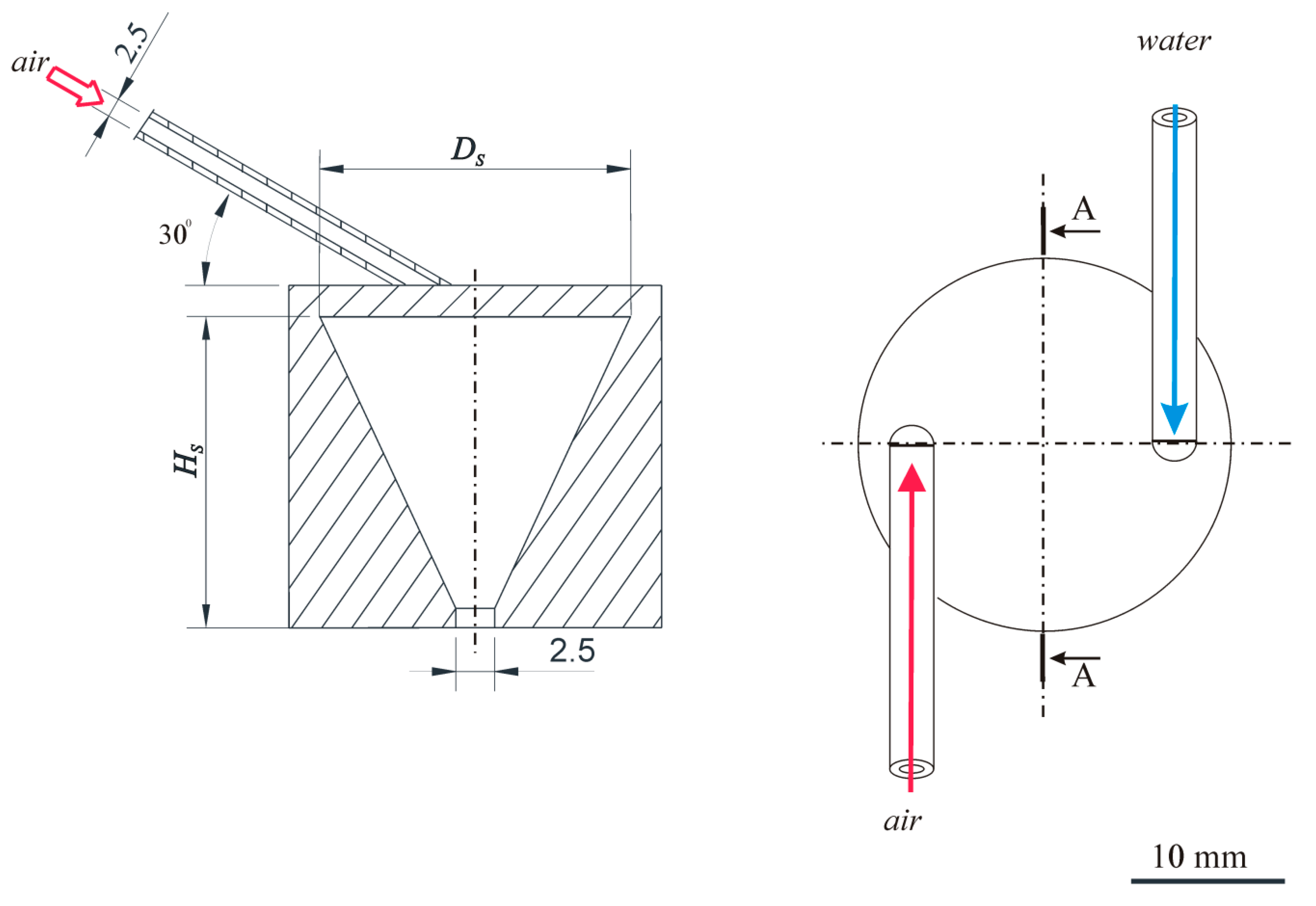
Figure 1 shows the geometry of the analyzed atomizers.
Table 1 presents the detailed characteristics of selected atomizers and the designations used in the further part of the work.
Numerical calculations were performed with the use of computational fluid dynamics CFD using the ANSYS Fluent R18.1 software. Because the purpose of the CFD simulation was to visualize the nature of the flow inside the atomizer (phase velocities, volumetric fractions) and to determine the spraying angles, the Euler-Euler model was used. The Euler-Euler approach (Euler model) includes an averaged mass and momentum balance for each phase present in the system. The Euler model treats all phases as continuous fluids with different velocities, volume fractions, and physicochemical properties. The differential equations of mass balance (continuity equation) and momentum for turbulent flow must be solved along with the equations describing the turbulence model. The most popular and simplest turbulence model was used for the calculations, the k-ε model, which is characterized by both quick convergence and good stability of the calculation process [
23,
33,
34,
35,
36,
37,
38]. During the preliminary calculations, the k-ω and Reynold stress (RSM) models were tested, but their application resulted in slower convergence and lower stability of the calculation process. Based on that, it was decided to use the k-ε model.
ANSYS Fluent offers three options for the k-ε turbulence model for multiphase flows: mixture turbulence model (default), distributed turbulence model or per phase turbulence model. The calculations used a distributed turbulence model, applied when secondary phases are dispersed in a continuous phase. Turbulent predictions for the continuous phase
q are obtained with the standard k-ε model supplemented with additional conditions that include interfacial turbulent momentum transfer. Predictions of the size of turbulence for dispersed phases are obtained using Tchen’s theory on the dispersion of discrete particles by homogeneous turbulence [
31].
The equations describing the model for the continuous phase
q are as follows:
The turbulence quantities for the dispersed phase are not obtained from the transport equations. The time and length scales that characterize motion are used to evaluate dispersion coefficients, correlation functions and turbulent kinetic energy of the dispersed phase.
, αi, ρi, µi, are the phase-weighted velocity, volume fraction, phase density and viscosity, respectively.
The turbulent viscosity is calculated from the formula:
while the production of turbulence energy from the formula:
where:
Sij is a tensor of averaged deformation coefficients, terms
Πkq and
Πεq are source terms that can be taken into account to model a turbulent interaction between the dispersed phase and continuous phases. The values of the constants
C and the turbulent Prandtl numbers
σ in the k-ε turbulence model are as follows
C1ε = 1.44;
C2ε = 1.92;
Cµ = 0.09;
σk= 1;
σε = 1.3 [
31].
The geometries of the atomizers used in the calculations were created on the basis of the commercial DesignModeler program in accordance with the real dimensions presented in work [
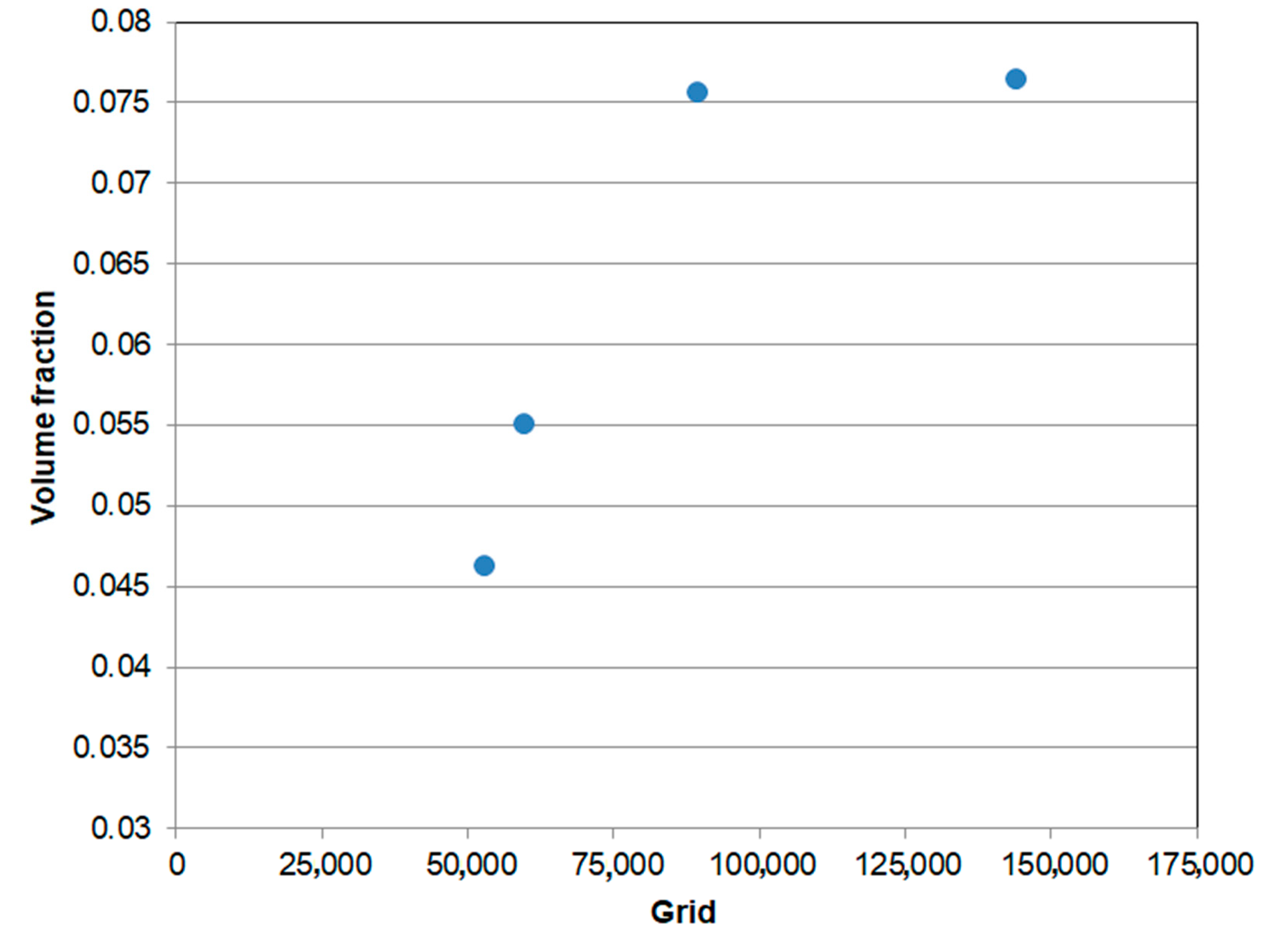
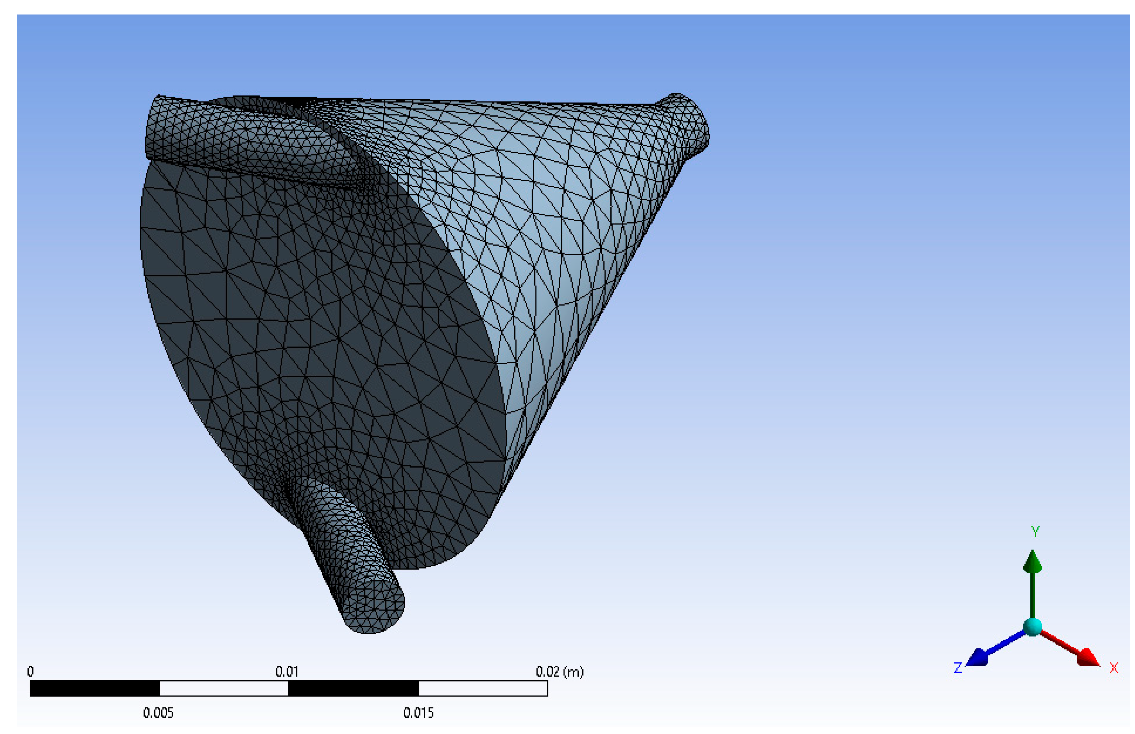
14]. In order to obtain reliable results of numerical calculations, a number of simulations were carried out, enabling the selection of an appropriate grid and time step for these calculations. Four types of meshes were generated to check the sensitivity of the mesh. For SAN-1 atomizer: 134,169, 118,704, 57,595, 42,048 cells, and for SAN-2 atomizer: 143,825, 89,301, 59,475, 52,736 cells. Calculations were performed for the generated meshes.
Figure 2 shows the results of the calculated mean liquid volume fractions at the outlet of the SAN-2 atomizer for each of these meshes.
Taking into account both the accuracy and the computational cost, the simulations used an intermediate mesh size, i.e., 89,301 cells. For a grid with 143,825 cells, with increased calculation time, the result was similar to that for a grid with 89,301 cells. By analyzing the calculation results for the SAN-1 atomizer identically, it was found that the mesh with 118,704 cells was the most optimal (
Figure 3). The quality of the computational mesh was determined using the skewness value, which for our meshes was: 0.233 for the SAN-1 and 0.231 for the SAN-2.
The boundary conditions: inlets with a specified velocity, an outlet with a specified pressure and no slip on the walls were also introduced to the program. The simulation for the transient state with a time step of 0.001 s was used for the calculations. The operating parameters ranges are shown in the
Table 2.
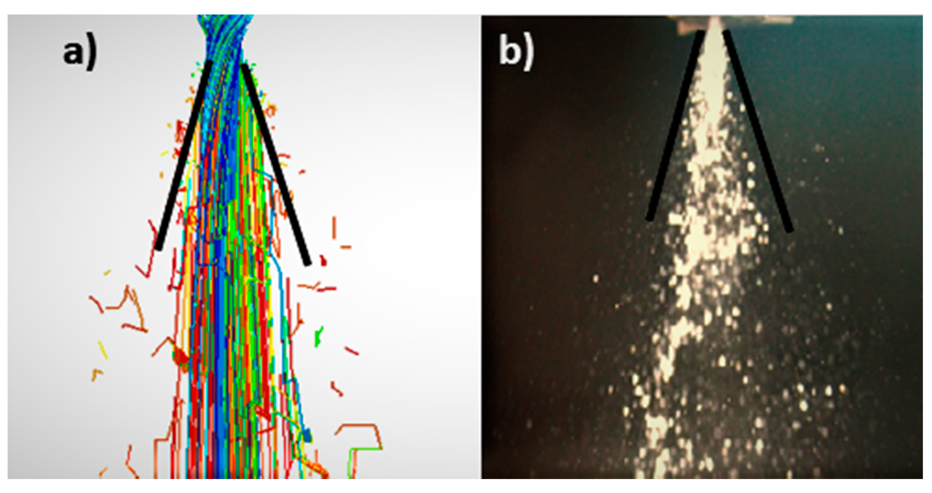
The numerical model was validated on the basis of the experimental results available in the works [
14,
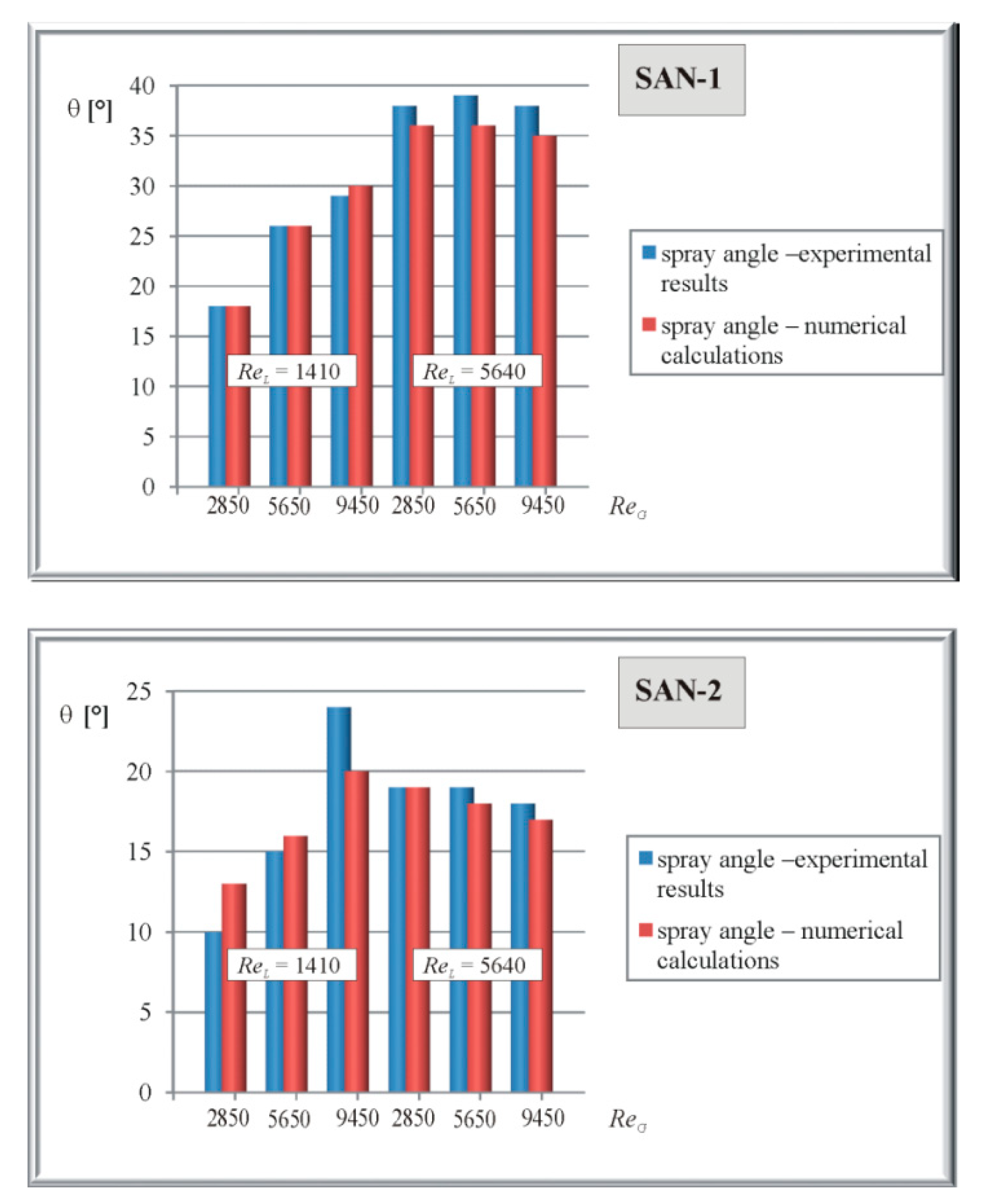
15]. The basis for determining the correctness of the calculations is a comparison of the compliance of the obtained spray angle values for individual test points. An exemplary summary of data concerning the spray angle obtained experimentally and using numerical simulations for the SAN-1 and SAN-2 atomizers and the methodology of comparison are shown in
Figure 4 and
Figure 5. The mean difference between CFD numerical calculations and experimental studies is around 6%. The maximum difference between numerical results and experimental data does not exceed 20%. The analysis of the obtained data showed that, with the increase of the Reynolds number for the gas, the spray angle value also increases.
In order to obtain reliable results of numerical calculations, a number of simulations were carried out, enabling the selection of an appropriate grid and time step for these calculations. Tetrahedral numerical grids composed of 89,301 to 118,704 elements were plotted on the defined structure (
Figure 1). The boundary conditions: inlets with a specified velocity, an outlet with a specified pressure and no slip on the walls were also introduced to the program. The simulation for the transient state with a time step of 0.001 s was used for the calculations.
3. Results
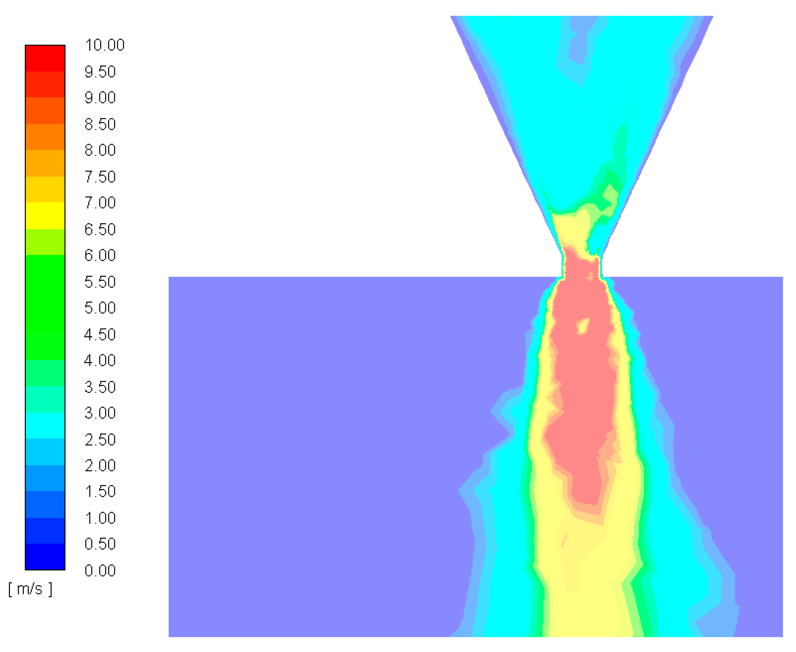
Figure 6 shows an example of the fluid flow velocity field inside the selected atomizer (SAN-1) and after leaving the system with the preset operating parameters
ReL = 4250 and
ReG = 3960.
It can be observed that higher liquid velocity and greater turbulence occur in the central part of the spray. Three velocity ranges can then be distinguished: the widest area of low velocity, the area of medium velocity and the narrowest area of high velocity. The maximum velocity is noticeable at the outlet of the atomizer. Then, as the spray becomes conical in shape, the velocity of the liquid slows down. This is the result of resistance forces (dependent on kinetic energy and aerodynamic drag) and the interaction of the droplets with the induced air movement, which is confirmed by the literature data presented by Sun et al. [
37] and Shi and Kleinstreuer [
39]. The expansion of the spray is facilitated by the radial velocity component. It also intensifies diffusion into the air.
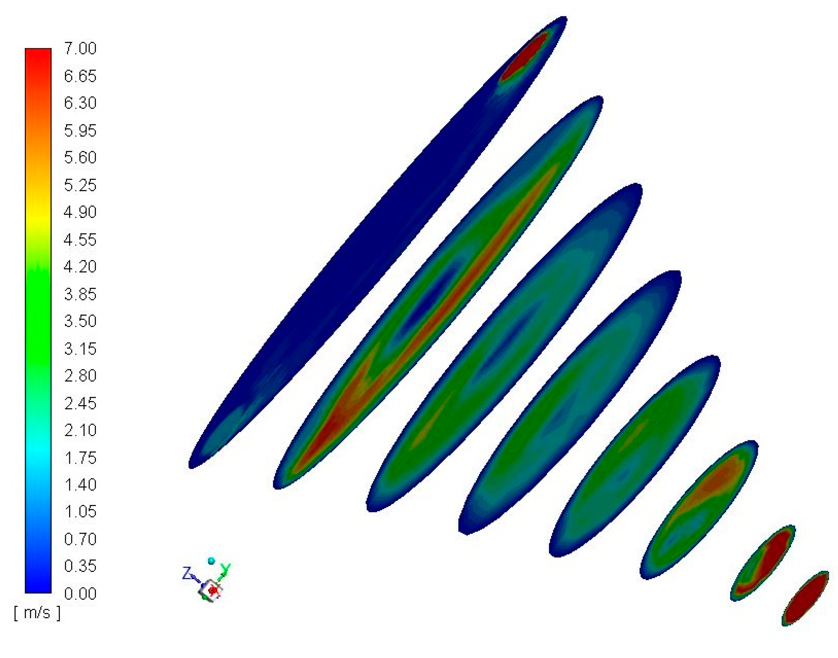
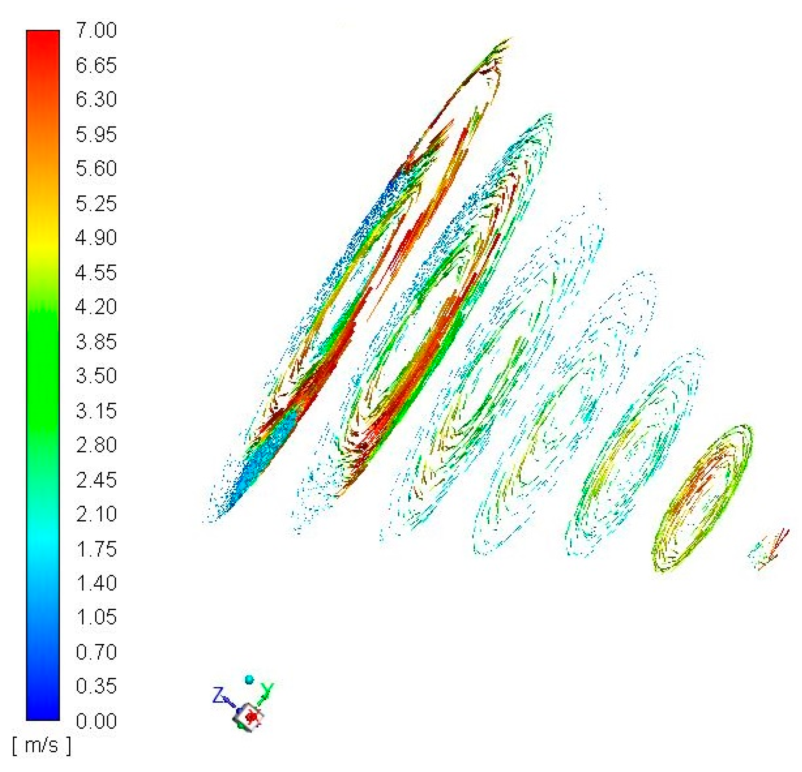
Figure 7 and
Figure 8 illustrate the velocity field distribution in selected cross-sections for the SAN-1 atomizer at the media flow defined as
ReL = 4250 and
ReG = 5650.
The obtained images confirm the formation of swirl motion inside the mixing chamber and the increase in the velocity of the liquid flow towards the nozzle outlet of the atomizer. The formation of the air core inside the atomizer is due to the centrifugal forces induced by the tangential introduction of both media. The flow of the two-phase mixture in the outlet becomes fully annular. The liquid flows as a thin film over the wall of the outlet orifice, and the gas flows at high velocity in the center of the outlet. This effect is desirable due to the accumulation of surface energy, increased stream instability, and thus increased susceptibility of the liquid to decay, i.e., improved atomization quality.
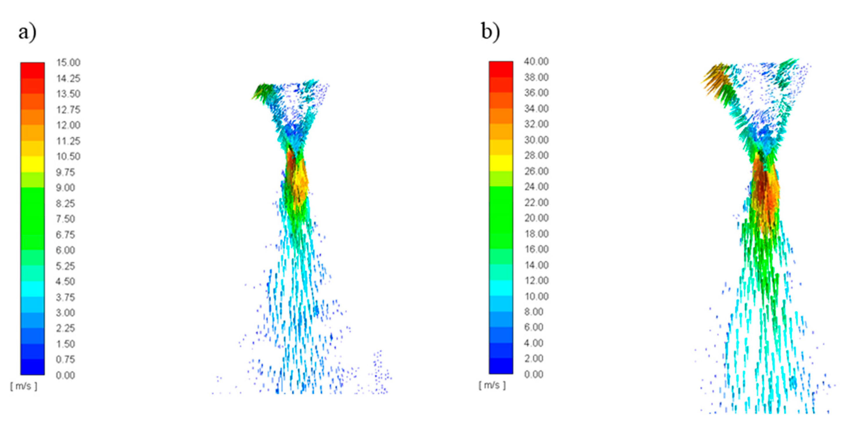
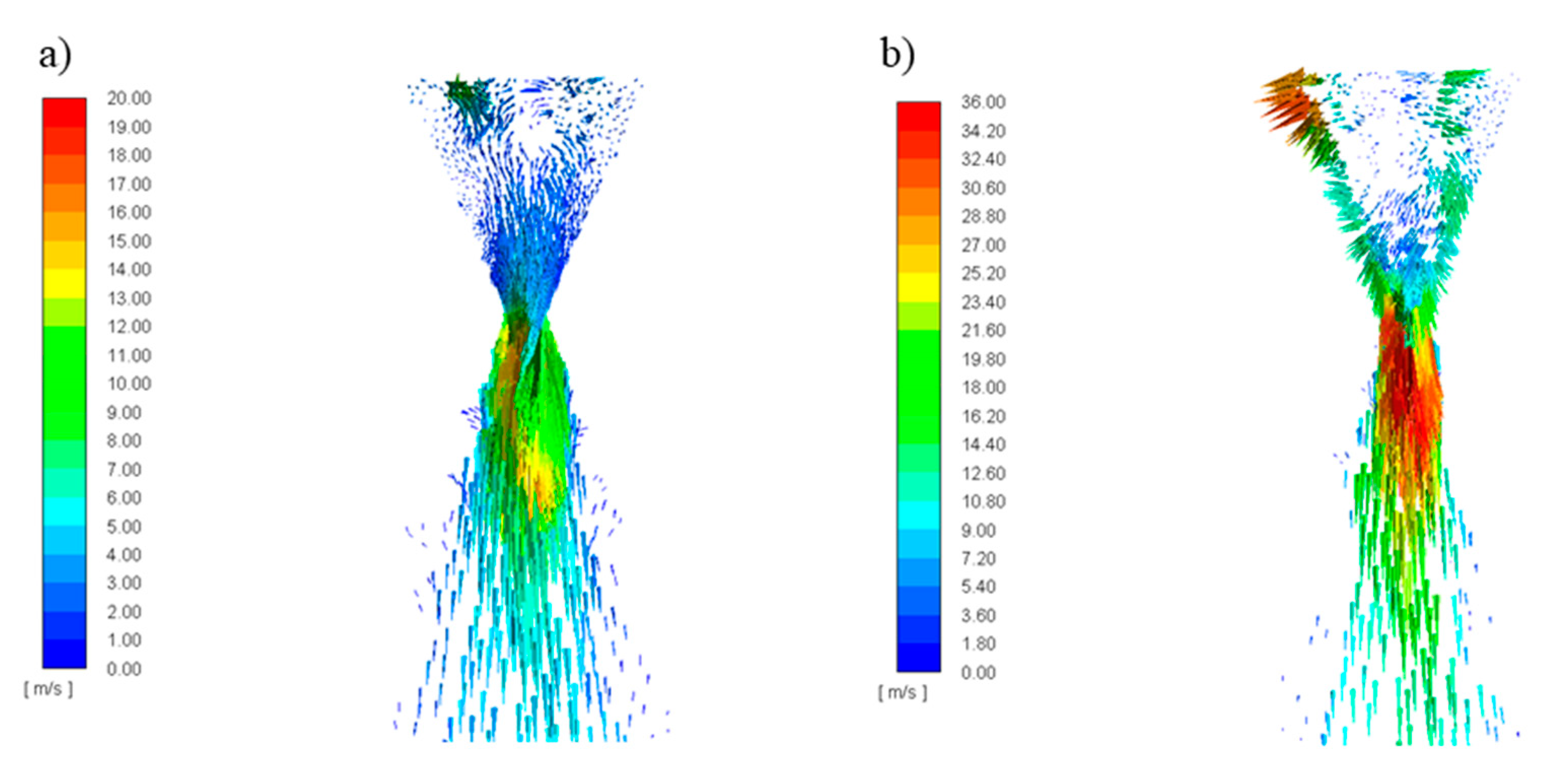
Figure 9 and
Figure 10 show the effect of changing the flow conditions of individual media on the obtained atomization effect and liquid velocity. With the increase of the Reynolds number of the liquid, with the constant Reynolds number of the gas, a larger spray angle was observed. On the other hand, the increase in the Reynolds number of the gas with the constant Reynolds number of the liquid resulted in a significant (about threefold) increase in the velocity of the liquid, especially in the central area of the aerosol. Moreover, in all the cases, the maximum speed of the droplet is observed in the central region of the generated spray.
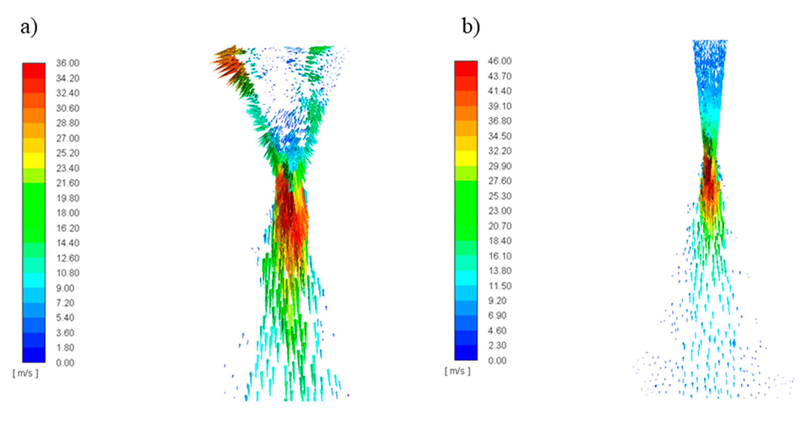
The geometry of the atomizer also influences the obtained liquid velocity distribution.
Figure 11 shows the results obtained for the SAN-1 atomizer (
HS/
DS = 1) and the SAN-2 atomizer (
HS/
DS = 4).
On the basis of the obtained images, using the AutoCAD software, the spray angle was measured, defined as the angle formed between two straight lines along the stream flowing out of the atomizer. It can be noticed that for the SAN-2 atomizer the spray angle was smaller than for the SAN-1 atomizer. It is related to the increase in the height of the atomizer swirl chamber while maintaining the same diameter (increase in the
HS/
DS ratio). The specific elongation of the swirl chamber reduces the angle of the transition cone in the atomizer (transition section of vortex chamber), which clearly translates into the spray effect obtained. This confirms the earlier observations suggesting that, when the value of the geometric invariant
HS/
DS ≥ 3, lower spray angle values are observed. The increase in the height of the swirl chamber causes the generation of additional frictional resistances, which results in a decrease in the momentum of the quantity of motion, which translates into a reduction of the spray angle obtained. In addition, in the case of the SAN-2 design, the effect of obtaining three velocity ranges in the spray is particularly visible. The effect of changing the geometry on the atomization quality is directly related to the nature of the flow inside the atomizer. The disintegration of the liquid stream is the key variable influencing the resulting spray [
40].
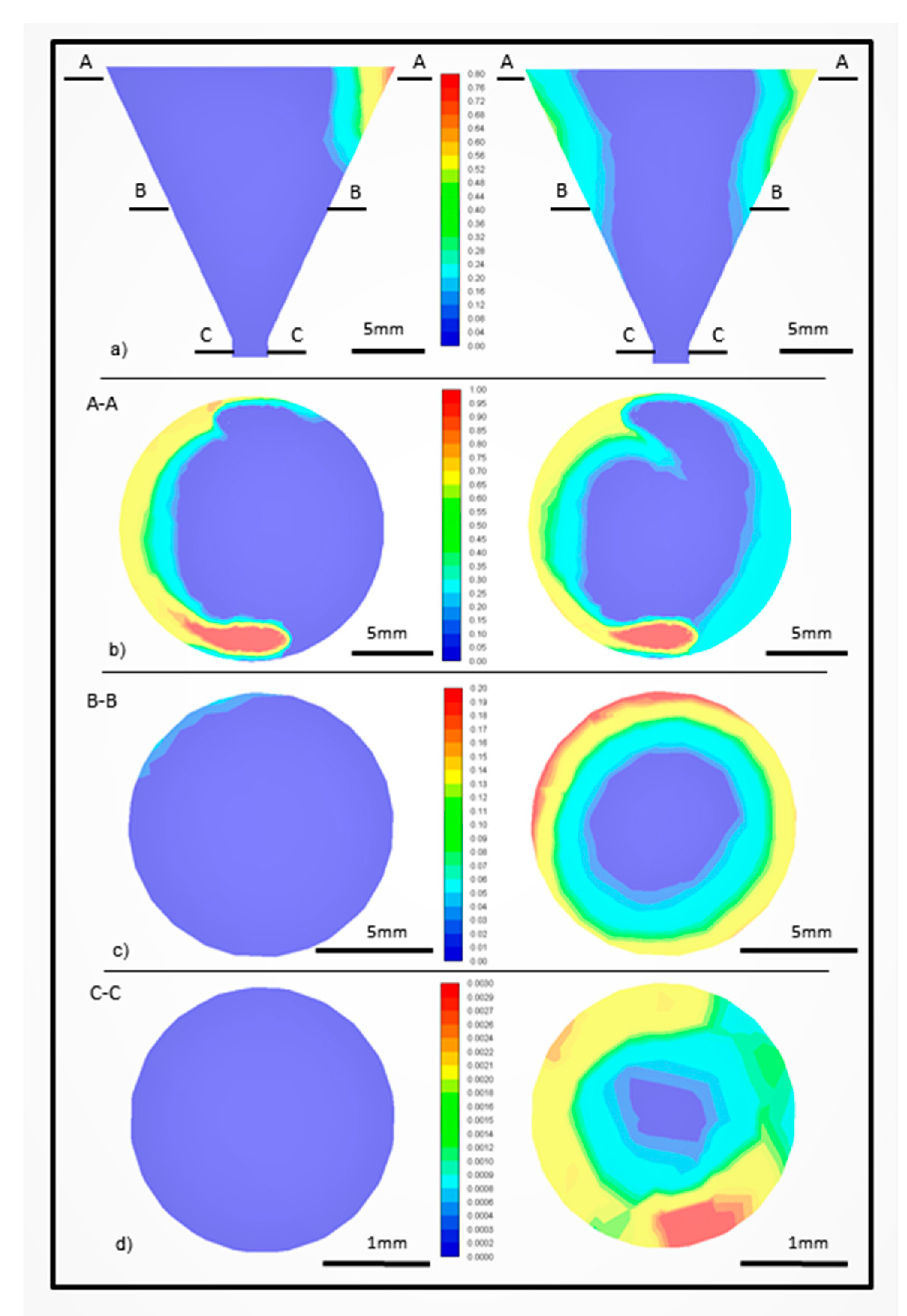
Figure 12 and
Figure 13 show the volume fraction of the liquid phase and its velocity in the mixing chamber for the SAN-1 and SAN-2 atomizers, respectively, at the same flow conditions
ReL = 1410,
ReG = 9500.
In the case of the SAN-1 atomizer, the breakdown of the stream inside the swirl chamber is much greater than for the SAN-2 atomizer. For the SAN-1 atomizer, only a narrow field at the top of the mixing chamber is visible, where the concentration of the liquid is significant, further along the entire chamber, we have a negligible fraction of liquid, which proves its significant dispersion. For the SAN-2 atomizer, the fraction of the liquid phase is visible on a considerable length of the swirl chamber, near its wall. Thus, it can be concluded that the liquid stream decomposition in this structure takes place to a lesser extent.
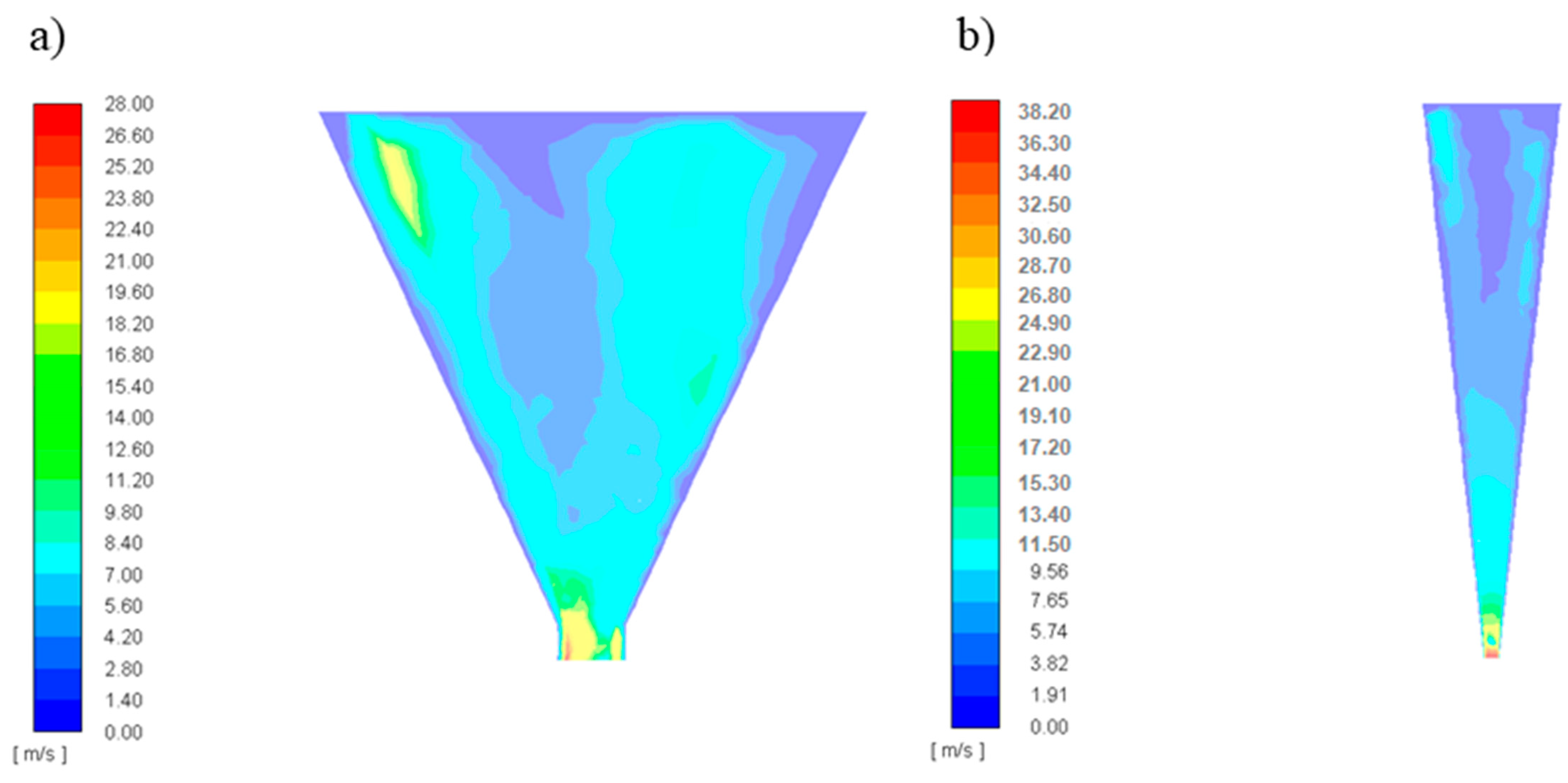
Figure 9 summarizes the velocity of the liquid inside the atomizer. For the SAN-1 system in the outlet orifice, it can be noticed that higher velocities are at its walls, while for the SAN-2, the liquid flows out the same through the entire cross-section of the outlet. This suggests that in the SAN-1 atomizer, the air core is in the central part of the outlet orifice, and in the case of the SAN-2 the liquid flows out through the entire cross-section. The differences in the internal flow for the analyzed atomizers are also related to the air core formed in a different way. In the SAN-1 atomizer, the core is formed with a much larger diameter than in the SAN-2 atomizer. Moreover, in the first case, the core is observed to be kept practically along the entire length of the swirl chamber, while in the second case, the core vanishes relatively quickly.
Figure 14 shows the effect of changing the operating parameters on the liquid dispersion inside the swirl chamber of the SAN-1 atomizer. The volume fraction of liquid was measured for three projections in the XY plane at different heights of the swirl chamber and in the XZ plane. The images in the left column are for the flow at
ReL = 1410,
ReG = 2850, while in the right:
ReL = 5650,
ReG = 2850.
It can be noticed that an increase in the liquid flow rate (liquid Reynolds number) for the same gas flow results in poorer and later liquid dispersion. At high liquid flow rates, we obtain a thicker liquid film (with a thickness of
s) on the inner walls of the swirl chamber, surrounding the air core. The air that was outside and was sucked in due to the pressure gradient, as well as the air that is supplied to the atomizer as a second phase, are in the swirl chamber and both contribute to the formation of the air core and affect the resulting spray. The diameter of the air core is smaller than the diameter of the atomizer outlet orifice. The air core primarily affects the actual outlet orifice cross-section occupied by the liquid, which is less than:
The more liquid is fed to the atomizer, the more difficult it is to disperse it. A solid stream of liquid is harder to tear. The formation of the air core in connection with the spray angle, droplet diameter and the flow velocity of the liquid in the spray was described, among others, by Durdina and his colleagues in their works [
41].
Figure 15 shows that the turbulent kinetic energy is high in the core region due to high shear rates and interphase coupling, since the dispersion is high in this region. The high intensity of turbulence at the orifice is associated with the high flow velocity of the fluid. The turbulent kinetic energy is highest (103 m
2/s
2) at nozzle orifice. The build-up of turbulent kinetic energy is observed in the axis of symmetry of the atomizer outlet, and in the result in the axis of the spray. A better understanding of the turbulence generated by the spray system can be beneficial for the evaluation of several important phenomena such as explosion enhancement.
The tested atomizers designs are a very attractive proposition, because they can have outlet openings with very large diameters, and by appropriately changing the geometry of the atomizer, the thickness of the liquid film can be made thicker or thinner. It has been shown that at low flow velocities, the liquid flows out of the atomizer in a dense stream, from which individual drops can detach. As the gas stream increases, the liquid stream is atomized into droplets and the spray angle increases. When the gas stream is relatively large, the spray angle may decrease due to the flowing around the stream of the atomized liquid. Increasing the stream of liquid may increase the volume of the stream, which makes it more difficult to disintegrate.
4. Conclusions
Two-phase flows are characterized by high complexity and difficulty in defining the conditions for the formation of appropriate structures. There are still no theoretical models to describe the phenomenon of two-phase atomization. The conducted research and calculations are aimed at increasing the knowledge about atomization obtained thanks to the use of two-phase atomizers with swirl flow. Numerical calculations were performed with the use of computational fluid dynamics CFD using the ANSYS Fluent R18.1 software. The analysis of the obtained data showed that with the increase of the Reynolds number for the gas, the spray angle value also increases. In the spray axis, the highest values of liquid flow velocity and the greatest swirls (turbulences) were observed. The impact of geometry change on the atomization quality is directly related to the nature of the internal flow and the air core formed. In the atomizer with HS/DS < 3, the air core is formed with a much larger diameter than in the atomizer HS/DS ≥ 3. Moreover, in the first case the air core is kept practically along the entire length of the swirl chamber, while in the second the air core decays relatively quickly. As the height of the swirl chamber increases, while maintaining its constant diameter, a decrease in the value of the transition section cone angle is observed. This results in less contraction of the stream, which translates into a reduction in the angular momentum. As the value of the HS/DS ratio increases, the spray angle value decreases. The increase in the height of the swirl chamber results in additional frictional resistance, which causes a decrease in angular momentum.
The correctness of the performed numerical simulations was verified by measuring the obtained spray angles and comparing its values with the data obtained experimentally. CFD analysis allowed for a more detailed analysis of the atomization mechanism providing information about the droplet velocity. Moreover, it made it possible to characterize the two-phase flow along the atomizer by determining the proportion of phases in the two-phase mixture. It is also a basis for further analysis of mass and energy exchange along the atomizer. The outcomes from this numerical calculation allow the optimization of the atomizer construction for specific applications and extend the classical analysis without time-consuming and costly experimental tests. Numerical simulations in modelling the phenomenon of spray formation and spreading can reduce costly tests and experimental studies. They can be helpful in the search for an atomizer technical solution that will obtain a specific spray (spraying intentionally) or be used by designers in the search for an optimal solution.
