Article

Optimal Adaptive Gain LQR-Based Energy Management Strategy for Battery–Supercapacitor Hybrid Power System

1
Laboratoire d’Analyse des Signaux et Systémes, Department of Electrical Engineering, University of M’sila, M’sila 28000, Algeria
2
Electrical Engineering Laboratory, Department of Electrical Engineering, University of M’sila, M’sila 28000, Algeria
3
ICube CNRS (UMR 7357) INSA Strasbourg, University of Strasbourg, 67000 Strasbourg, France
4
IREENA Laboratory, University of Nantes, 44602 Saint-Nazaire, France
5
College of Engineering at Wadi Addawaser, Prince Sattam BinAbdulaziz University, Al-Kharj 11991, Saudi Arabia
6
Electrical Engineering Department, Faculty of Engineering, Minia University, Minia 61111, Egypt
*
Author to whom correspondence should be addressed.
Energies 2021, 14(6), 1660; https://doi.org/10.3390/en14061660
Submission received: 16 January 2021 / Revised: 26 February 2021 / Accepted: 27 February 2021 / Published: 17 March 2021

Abstract

:
This paper aims at presenting an energy management strategy (EMS) based upon optimal control theory for a battery–supercapacitor hybrid power system. The hybrid power system consists of a lithium-ion battery and a supercapacitor with associated bidirectional DC/DC converters. The proposed EMS aims at computing adaptive gains using the salp swarm algorithm and load following control technique to assign the power reference for both the supercapacitor and the battery while achieving optimal performance and stable voltage. The DC/DC converter model is derived utilizing the first-principles method and computes the required gains to achieve the desired power. The fact that the developed algorithm takes disturbances into account increases the power elements’ life expectancies and supplies the power system with the required power.

1. Introduction

Nowadays, with the expansion of the energy crisis and ecological pollution, hybrid power systems (HPSs) are becoming a strategic solution. Hybrid power systems (HPSs) are a set of co-operating power sources, and the coordination of their operation is realized using advanced power electronics systems [1]. Due to its advantages, a HPS can be employed for Electrical Vehicles (EV) (EV) applications [2,3,4] or stationary applications [5,6,7]. This has resulted in a spark of interest in the research field, with different hybridizations and energy management strategies having been developed to further reduce emissions and improve fuel economy [8].
Battery–supercapacitor HPSs are receiving more attention due to their superior performance and simplicity of control. The lithium battery, despite having a high energetic density, does not yield a high enough power density, while the opposite can be said about the supercapacitor. A hybridization thus proves suitable to increase both components’ lifetime and improve the overall performance, especially considering storage elements’ states of charge and temperatures. Using the supercapacitor in the case of sudden load variations is an example. In addition to that, high-frequency disturbances negatively affect the battery’s life expectancy, which can be alleviated by the supercapacitor due to its characteristics. The main challenge is to provide a suitable energy management strategy (EMS) that takes all of these factors into account to provide optimal performance while considering different constraints.
Various methods concerning the energy management of a hybrid power system have been reported in the literature [9,10,11]. They are generally divided into a group of three main methods: optimization-based methods, rule-based methods, or, more recently, learning-based methods. Figure 1 showcases the three main categories of energy management strategies and some of the methods involved.
Optimization-based methods make use of the tools provided by optimization theory to solve the problem at hand, the latter being an optimal distribution of the load power amongst the battery–supercapacitor hybrid system such that it improves upon their life expectancies given their respective constraints (state of charge and supercapacitor voltage, for instance). The optimization-based strategies can be subcategorized into two main groups: offline optimization (global optimization) strategies and online optimization (real-time optimization) strategies.
Offline optimization strategies are computationally complexed strategies, which require the pre-knowledge of the load profile. This makes it challenging to implement them in real-time. The most popular strategies are dynamic programming (DP) [12,13,14], stochastic dynamic programming (SDP) [15], and the genetic algorithm (GA) [2,16]. These strategies are mainly used as a benchmark to evaluate the performance of the other strategies.
The online optimization strategies are applicable in a real-time scenario, such as computing the optimal distribution of energy amongst a hybrid system given the power load. In this category, the cost function depends only on the actual state of the system [17]. Methods such as model predictive control (MPC) [18,19], the equivalent consumption minimization strategy (ECMS) [20,21], and the external energy maximization strategy (EEMS) [22] can qualify as online optimization methods.
Rule-based methods, on the other hand, can be summed into a series of IF-THEN scenarios. There are mainly three categories: deterministic rule-based strategies, Boolean logic strategies, and fuzzy logic strategies. State machine control (SMC) [23,24] is one of the most used strategies as a deterministic Boolean which is based on the hysteric controller. It can be easily implemented in a real-time scenario. Another method is to use a fuzzy logic-based EMS [25,26], which proves quite robust and makes its decision regarding the power distribution dependent on the output of its membership functions and can be easily tuned to achieve optimal operation. The main drawback of these methods is that the elaboration of said rules requires the knowledge and experience of an expert, which is not always available.
Learning-based methods make use of the recent advancements regarding machine learning (ML) such as reinforcement learning (RL) [27,28], and deep learning (DL) [29,30], a sub-field of artificial intelligence (AI), which has seen a surge in its use over the last decade. They have proven to yield excellent results in some fields, especially in image classification, hence their extensive use in some other fields, including energy management. A model has to be trained using a database, which is not always available. This can prove quite difficult, notably because not enough research has been conducted in this relatively recent field. Another drawback is the fact that they have no guarantee to work for data outside those used for training.
Despite their use in some cases [31,32], none of these strategies combined the advantages procured by the frequency decoupling approach and optimization-based strategies. The proposed method overcomes some of the drawbacks of the load following technique while providing the benefits of optimization-based methods, thus improving the overall HPS performance.
The load following (LF) strategy is a management strategy, which is mainly based on generating the power references based on the measured load power and the storage system state of charge. The LF strategy has been widely used for controlling hybrid power systems such as battery/SC or FC/battery/SC. Bizon et al. [33,34] proposed a real-time optimized LF strategy using global extremum seeking (GES).
The extremum seeking control (ESC) algorithm is an adaptive search technique for extremes of a nonlinear function [35]. However, this optimization strategy is very sensitive to the filter’s parameters. Thus, the design is very difficult.
The proposed method consists of combining the load following (LF) approach with an optimal control by using a linear quadratic regulator (LQR) in order to compute the control gains, which will be updated by means of the salp swarm algorithm. Comparing with the GES, this proposed strategy is very easy where the optimizer will update the control parameters without designer expertise. The models used in simulations were achieved through a literature review [36,37].
In order to distribute the required power between the two energy sources, a load following strategy (LFS) is adopted. The bus voltage will be stabilized by the supercapacitor due to its fast dynamics, while the battery will handle the load power and the supercapacitor required power. The main contribution comes from the usage of both a lower-level control architecture as well as a higher-level one, which allows improving the energy quality while diminishing the strains on the power sources, thus achieving a higher life cycle.
The main contributions of the paper are summarized below:
  • Robust control ensures a good energy quality provided to the load side and an extended Hybrid Energy Storage System (HESS) component lifetime;
  • Combination of different methods to achieve an optimal performance.

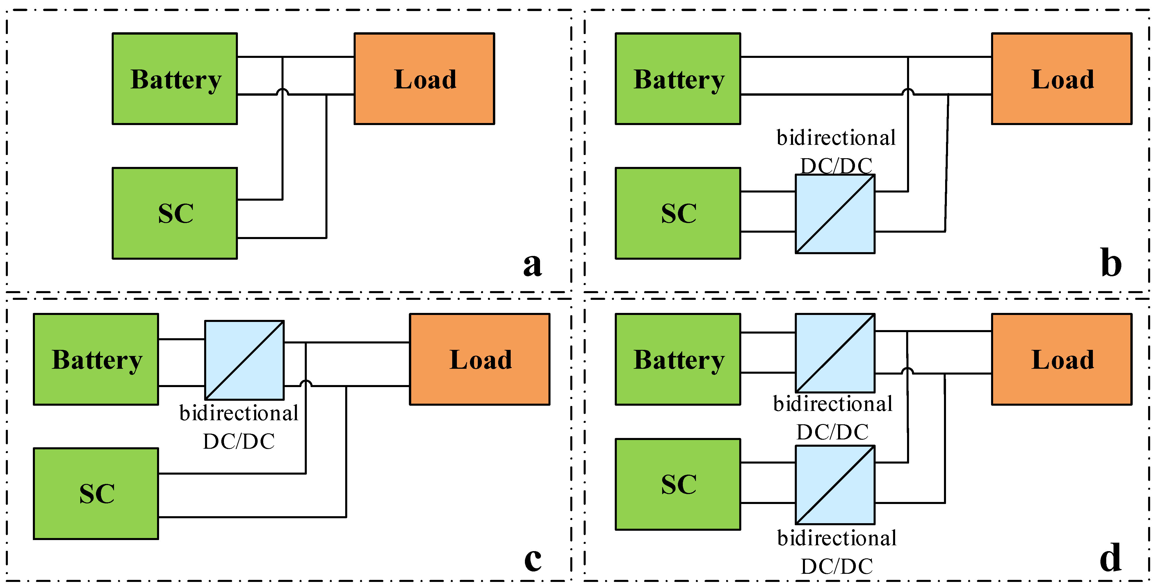
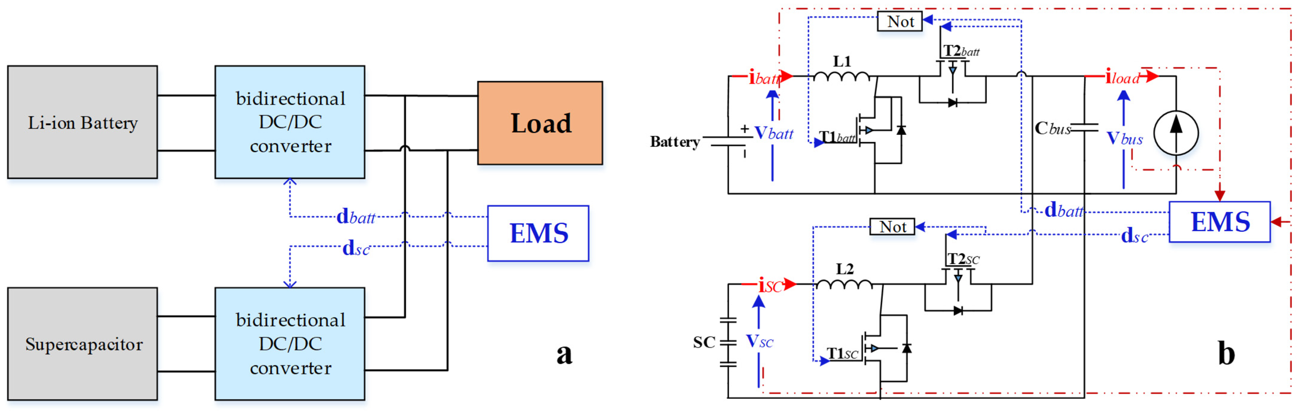
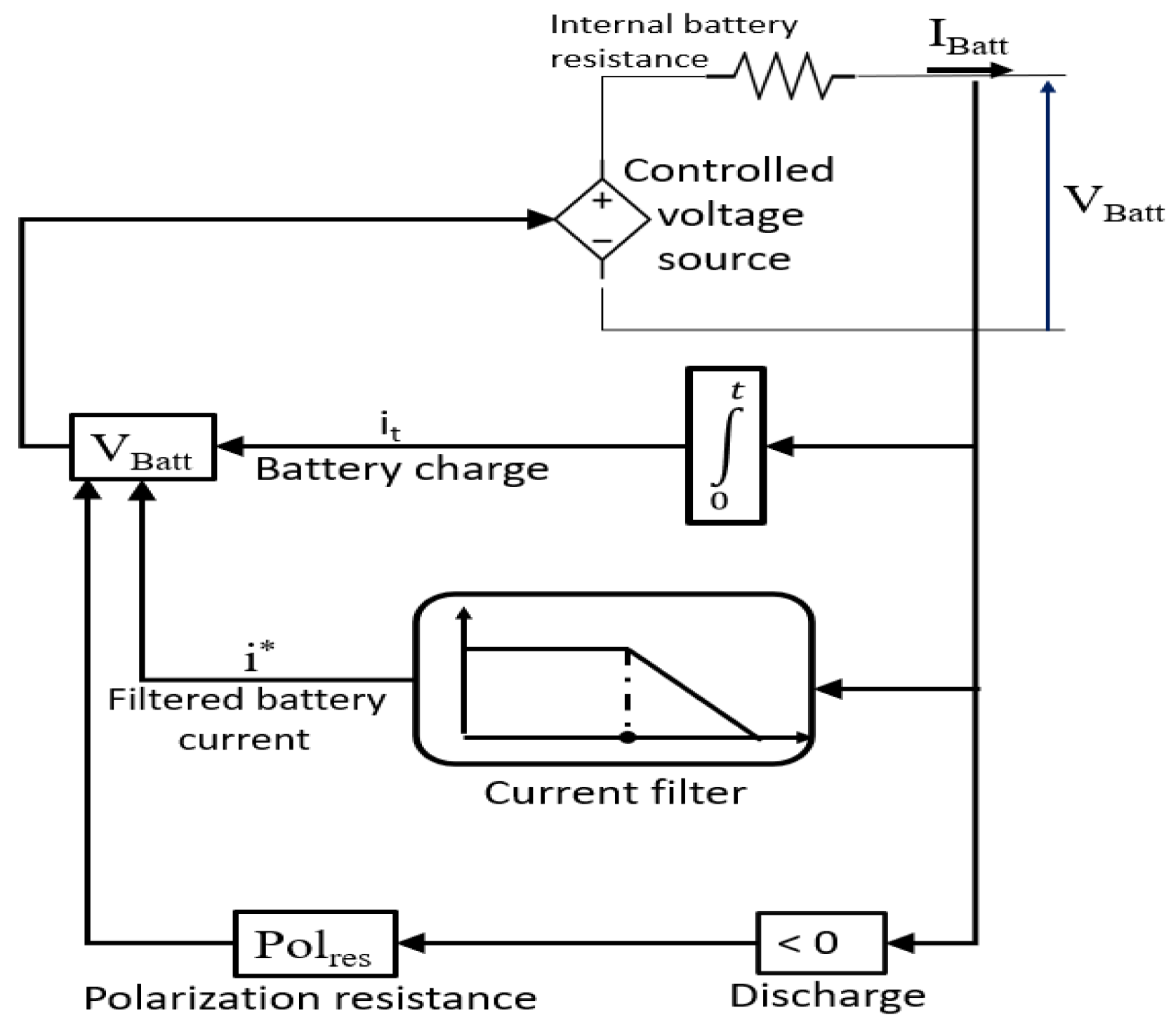
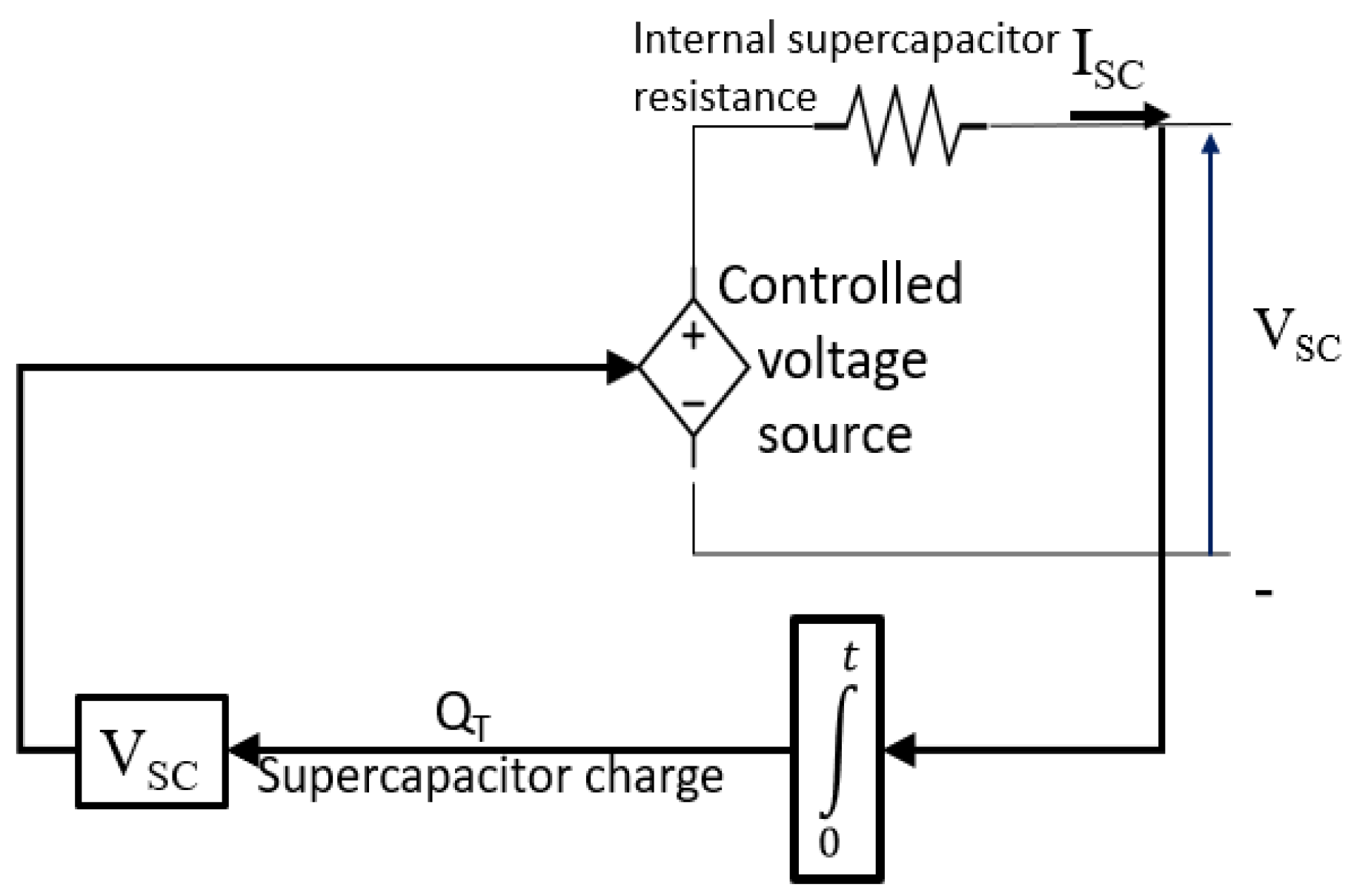
2. HPS Topology Structure and Modeling
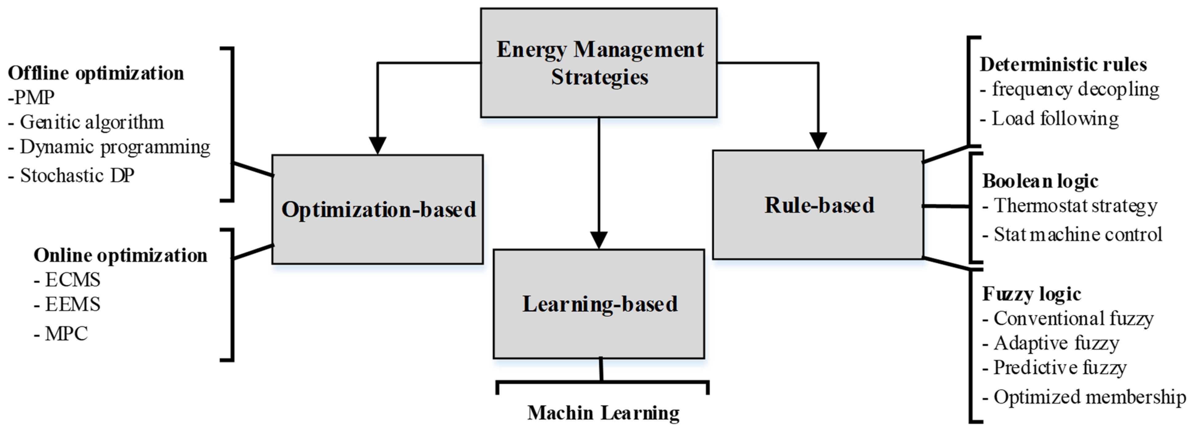
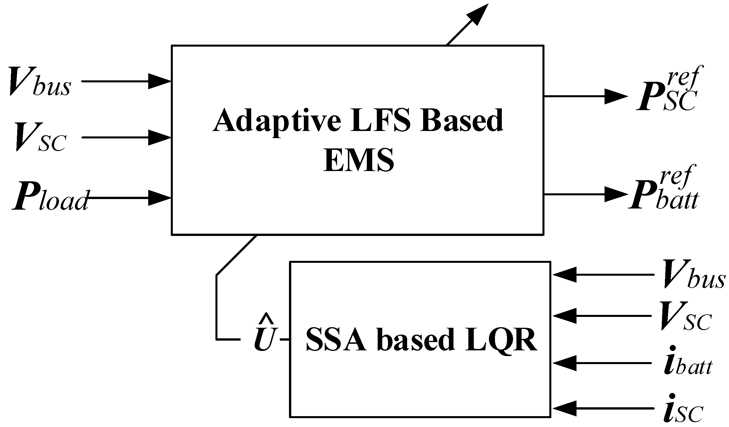
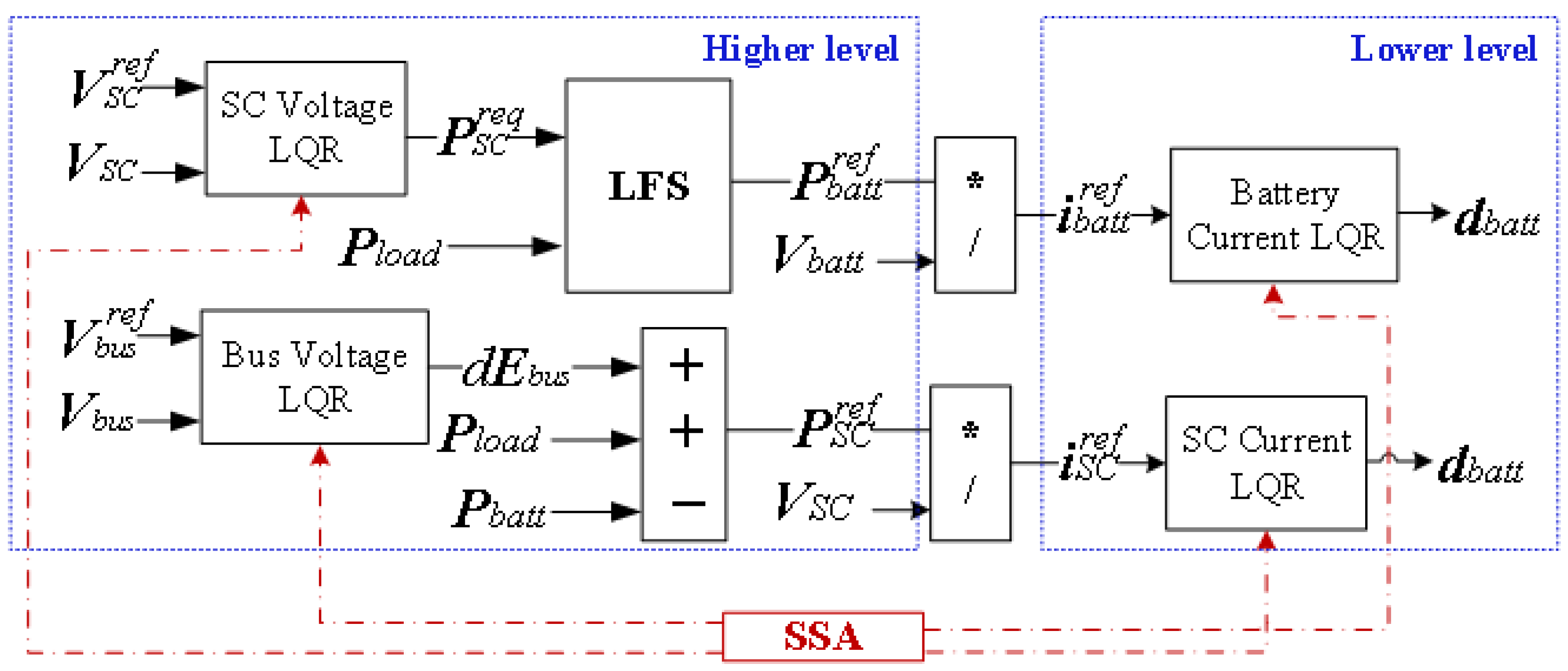
Batteries have the characteristics of a high energy density and relatively low power density. Moreover, the internal resistance could increase when the battery operates with high-frequency loads, which leads to its degradation. Supercapacitors have a high power density with a high number of charging/discharging cycles. Thus, the combination of a battery and a supercapacitor can provide a complementary advantage to meet the load demand [38].
In the literature, passive, semi-active, and active topologies have been reported. Each one has its characteristics. Figure 2 illustrates these topologies.
As displayed in Figure 3a, the configuration of the studied HPS is based on the fully active topology. The electrical power system is composed of a supercapacitor and a lithium battery, where each one of them connects the DC bus through bidirectional DC/DC converters to power the load, as detailed in Figure 3b. In this system, the proposed EMS is based on the optimal power-sharing method (LQR) that calculates the references to the low-level controllers in order to satisfy the load demand while a high-level control minimizes the DC bus overshoots under step loads.
In this paper, a Li-ion battery was selected as a principal source due to its proven efficiency and high energy density as opposed to other battery technologies. A model available in MATLAB’s SPS (SimPowerSystems) Toolbox was considered in order to validate the proposed EMS by simulation. The battery model depicted in Figure 4 is based on the Thévenin circuit. This battery model is detailed in [31]. The battery voltage is expressed as follows:
V b a t t = E 0 K Q Q i t R b i + A b e ( B i t ) K Q Q i t i *
where Vbatt is the battery voltage, E0 is the battery constant voltage (V), K is the polarization constant (V/Ah), Q is the battery capacity (Ah), i* is the filtered battery current (A), it is the actual battery charge (Ah), Ab is the exponential zone amplitude (V), B is the exponential zone time constant inverse (Ah(−1)), and Rb is the battery internal resistance (Ω). As for the polarization resistance Polres, which is only present when charging the battery, it is expressed as follows:
P o l r e s = K Q i t 0.1 Q
The detailed battery scheme is given in Figure 4.
Supercapacitors, despite not being able to withhold as much energy as Li-ion batteries, are able to release energy at a faster rate due to their high dynamics. The considered model also comes from MATLAB’s SPS Toolbox, where more details can be found in [4]. The supercapacitor output voltage VSC is given as follows:
V S C = Q T C T R S C i S C
where QT is the total electric charge (Coulombs), CT is the supercapacitor module capacitance, RSC is the supercapacitor module resistance (Ω), and iSC is the supercapacitor module current (A). It is dependent on the supercapacitor’s state of charge. The supercapacitor block is given in Figure 5.
Two main models are used throughout the literature: the switching model and the average one. The average model proves sufficient for this case. The switching models are mainly used for design purposes and to investigate types of pulse width-modulated schemes with regard to switching harmonics and losses. These models require a low sampling time to observe all the switching actions, which makes the simulation very time-consuming, hence the choice of an average model for this paper.
{ L 1 d i b a t t d t = V b a t t V b u s d b a t t R b a t t i b a t t L 2 d i S C d t = V S C V b u s d S C R S C i S C C b u s d V b u s d t = d b a t t i b a t t + d S C i S C i b u s

3. The Proposed EMS

The proposed EMS is based on the load following strategy (LFS). It possesses two main components: a lower-level controller and a higher-level one. The power reference for each source is generated by the higher-level controller, while the lower-level one compensates for the DC bus current fluctuations, ensuring an optimal performance paired with an overall better energy quality. The operating control scheme is illustrated in Figure 6.
At the higher-level EMS, the supercapacitor power regulates the DC bus voltage and handles the high-frequency power. The DC power reference is generated based on the DC bus voltage, where an LQR is used to stabilize it. The available bus energy can be expressed as
d E b u s d t = P S C + P b a t t P l o a d
where Ebus is the bus energy, and Pload, PSC, and Pbatt are the load, supercapacitor, and battery powers, respectively. The supercapacitor power reference can be obtained as
P S C r e f = d E b u s d t P b a t t + P l o a d
where the required power by the bus can be obtained using an LQR controller.
The battery mainly feeds the load and maintains the DC voltage at the reference value. An LQR controller is used for generating the SC required power. The control law can be written as
P b a t t r e f = P S C r e q + P l o a d
where the supercapacitor power required is generated by an LQR controller.
The lower level generates the duty cycle for each converter, based on the generated power references. The current references will be generated and compared with the measured ones. The regulation process will be achieved using the current LQR. The adaptation of the controller parameters will be realized by means of the SSA real-time optimizer. The detailed control scheme is described in Figure 7.
The LQR (linear quadratic regulator) is an optimal controller that is used extensively due to its solid performances. It relies upon the minimization of the cost function J:
J = 0 ( x T Q x + u T R u ) d t
where Q and R are the control parameters, and u is the control signal. A state feedback control is present by: U = −Kx(t), U being the control input, x(t) the state vector, and K = R(−1) BT. S is the gain matrix defined as
K = R 1 B T S
While S is the symmetric positive definite solution to the algebraic Riccati equation:
Q + A T S + S A S B ( R 1 ) B T = 0
A and B are the model state space matrices.

3.1. LQR Controller

Q and R are symmetric positive definite weighing matrices. They are chosen depending on the desired closed loop performance, with the Q matrix penalizing the states while the R matrix penalizes the actuators. An augmented system regrouping the battery’s and the supercapacitor’s voltages and currents is given:
The control law U becomes
U = R 1 B T S x = K x
where the LQR matrices are provided in the Appendix A.
{ U 1 = k I i S C ( i S C r e f i S C ) d t + k P i S C ( i S C r e f i S C ) U 2 = k I i b a t t ( i b a t t r e f i b a t t ) d t + k P i b a t t ( i b a t t r e f i b a t t ) U 3 = k I V b u s ( V b u s r e f V b u s ) d t + k P V b u s ( V b u s r e f V b u s ) U 4 = k I V S C ( V S C r e f V S C ) d t + k P V S C ( V S C r e f V S C )
where k I i S C and k P i S C are the supercapacitor current controller’s integral and proportional gains, and i S C r e f and i S C are the supercapacitor’s reference and measured currents; k I i b a t t and k P i b a t t are the battery controller’s integral and proportional gains, and i b a t t r e f and i b a t t are the battery’s reference and measured currents; k I V b u s and k P V b u s are the DC bus controller’s integral and proportional gains, and V b u s r e f and V b u s are the DC bus’s reference and measured voltages; k I V S C and k P V S C are the supercapacitor voltage controller’s integral and proportional gains, and V S C r e f and V S C are the supercapacitor’s reference and measured voltages.

3.2. SSA Optimizer

The salp swarm algorithm (SSA) is a meta-heuristic algorithm created by Mirjalili [39]. This optimizer is inspired by the movement of salps in the ocean. It is mainly characterized by its fast resolving and high precision. In the agent set, there are two types of agents: leader and followers, where the movement of each one can be modeled as
L P ( k ) = { F P ( k ) + c 1 ( ( u b l b ) c 2 + l b )   i f   c 3 < 0.5 F P ( k ) c 1 ( ( u b l b ) c 2 + l b )   i f   c 3 > 0.5
c 1 = 2 e ( 4 k T m a x ) 2
where L P ( k ) is the leader position at iteration k, F P ( k ) is the food position (the target) at iteration k, and c2 and c3 are random variables [0,1]. ub and lb are the upper and lower search space limits. The follower’s movement can be modeled as
F P i ( k ) = 0.5 ( F P i ( k 1 ) + F P i 1 ( k ) )
where F P i ( k ) is the i-th follower position, where it updates its position according to its position and the precedent agent position.
The objective function is to minimize the voltage reference and ensure safe operating to the HPS. The objective function can be written as a function of the error as
o b j F u n = min ( 0 t ε d t )
For the HPS, there are four errors: the bus voltage error, the supercapacitor error, the battery current error, and the supercapacitor error.
{ ε V b u s = V b u s r e f V b u s ε V S C = V S C r e f V S C ε i b a t t = i b a t t r e f i b a t t ε i S C = i S C r e f i S C
Based on the measured objective function, which is the integral square error, the SSA generates the following parameters: k I i S C , k P i S C , k I i b a t t , k P i b a t t , k I V b u s , k P V b u s , k I V S C and k P V S C .

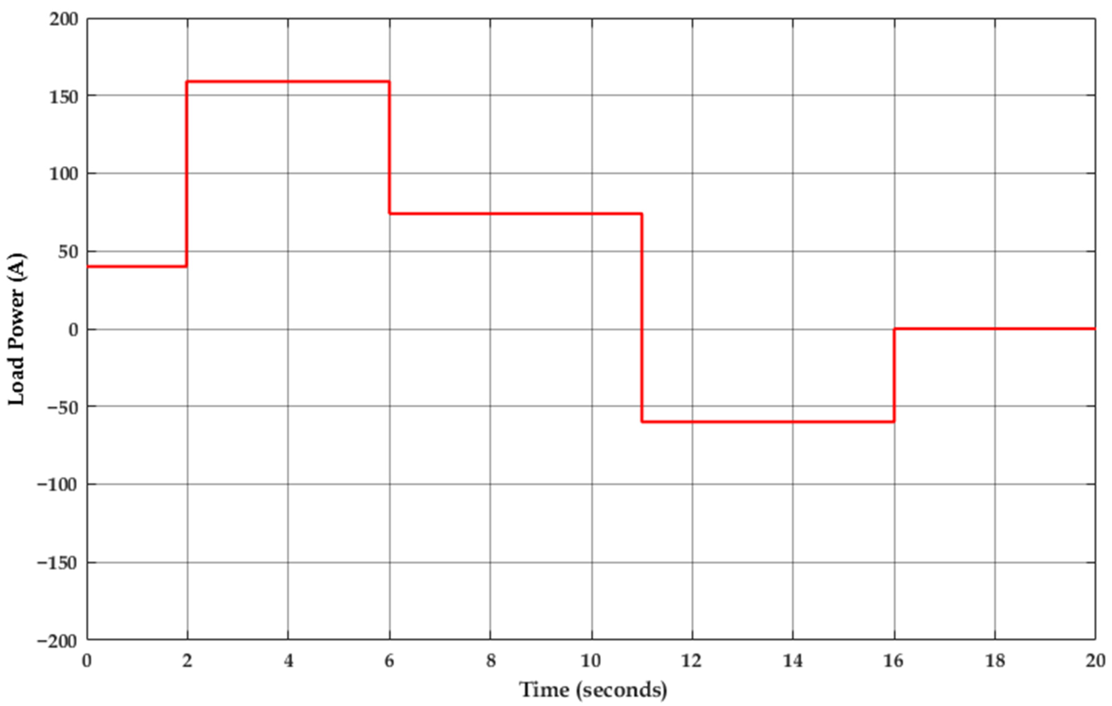
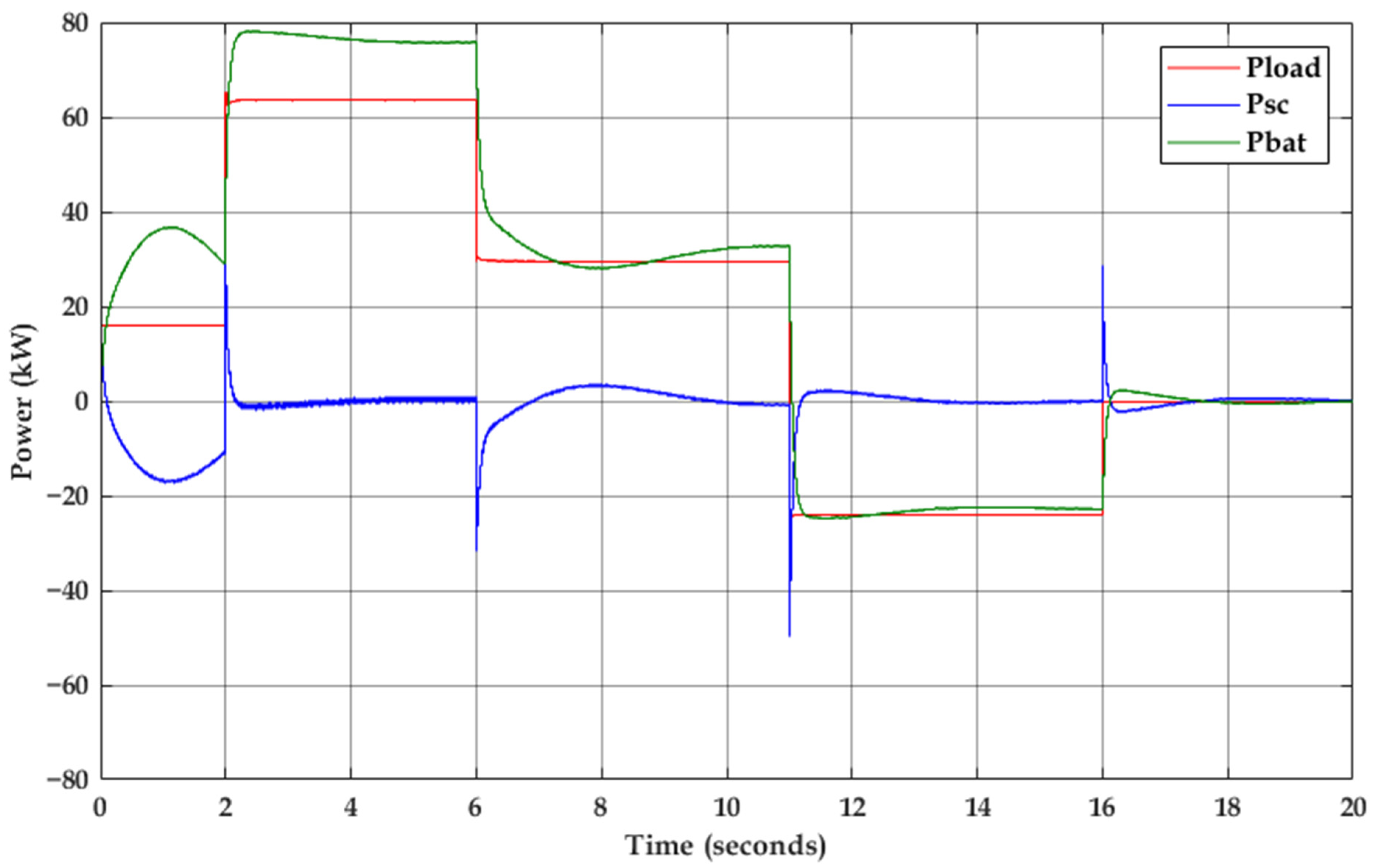
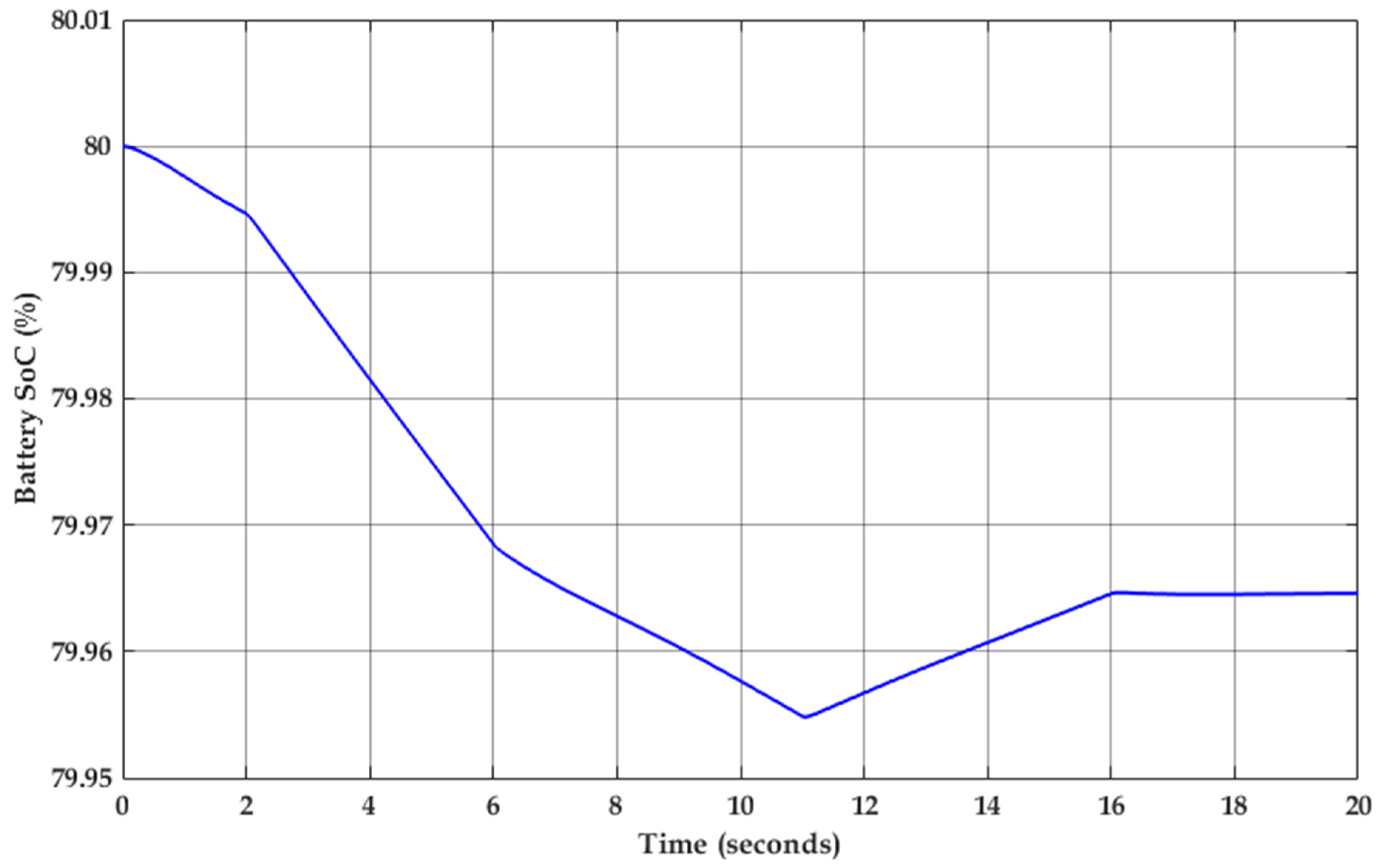
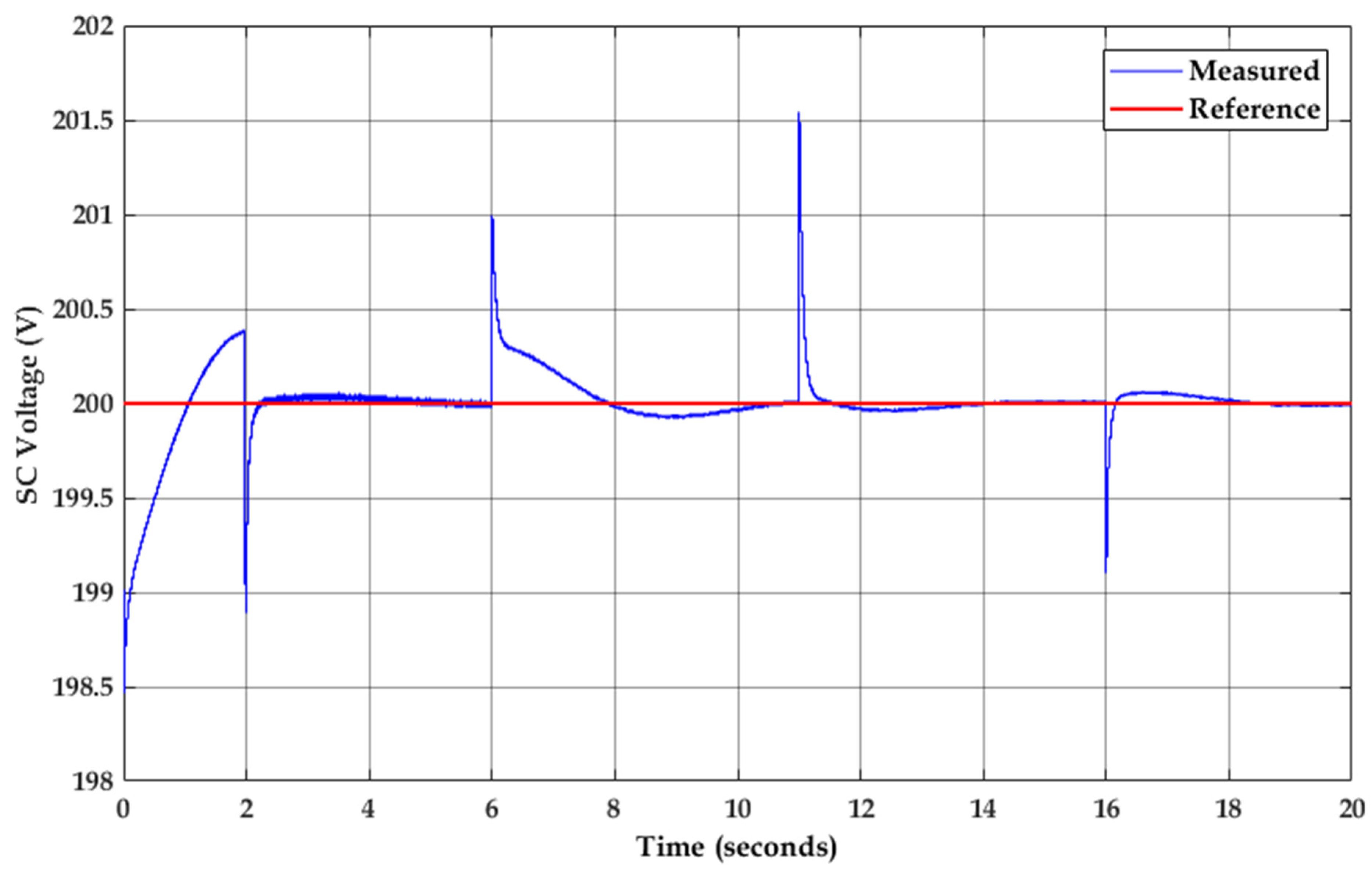
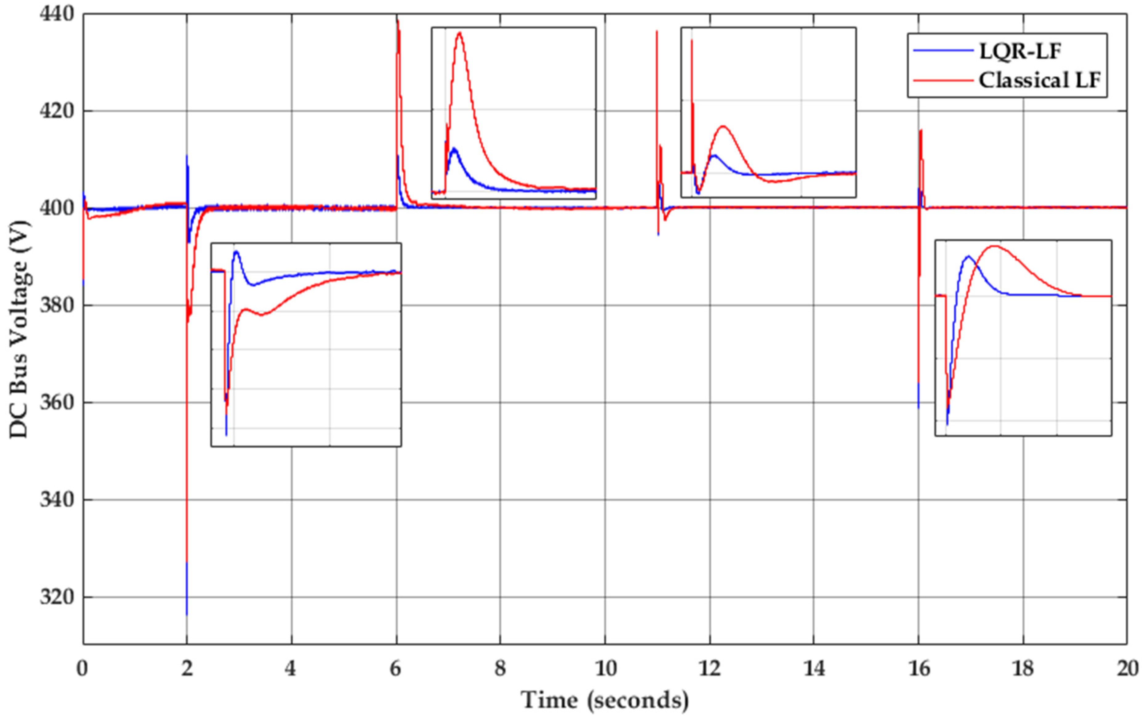
4. Simulation Results

In this part, MATLAB-Simulink is used to validate the proposed EMS. The system parameters are summarized in Table 1, where R1 and R2 are the internal converter resistors (Ω); L1 and L2 are the converter inductors (mH); VSC ref is the SC voltage reference (V); V b u s r e f is the (V); CSC and Cbus are the SC and the bus capacitance values, respectively (F); Cbatt is the battery capacity (Ah).
To validate the performance of the proposed EMS, the load profile illustrated in Figure 8 is used. The simulation results are given in Figure 9. At the beginning, the load is positive, which is supplied by the battery, then it will be negative, and the battery will charge itself. The battery State of Charge (SoC) is given in Figure 10.
As illustrated in Figure 9, the load is mainly provided by the battery, where the supercapacitor supplies the transitory power, which means that its average power is zero. The battery charges the supercapacitor to hold its voltage at the reference value, where the initial supercapacitor voltage is less than the reference, as illustrated in Figure 11. Thus, the supercapacitor power is negative to charge itself.
The proposed EMS stabilizes the bus voltage against the high steps in the load power. The optimal updating mechanism allows the LQR voltage controller to change its parameters depending on the error between the measured and the reference voltage, which enhances the controller performance. The bus voltage is illustrated in Figure 12. The proposed control method is compared with the classical LF strategy.
The proposed strategy updates its control parameters depending on the measured objective function; thus, the system performance is improved, as illustrated in Figure 12.
To emulate the real load behavior, the load profile represented in Figure 13 is used. The simulation results are given in Figure 14. The battery SoC is presented in Figure 15.
As given in these figures, the load is principally supplied by the battery power, where the fast load variations are supplied by the supercapacitor power.
The optimal adaptive LQR controllers successfully stabilize the bus and the supercapacitor voltage, as represented in Figure 16 and Figure 17.
In this case, which emulates the real load demand, the bus voltage is stabilized where the maximum overshoot voltage is 5.6 V (1.25%) for significant steps in the load (about 60 A/s). The voltage ripple is minimized by means of the optimal adaptation process (ΔV = 4 V).
The obtained results from Figure 12 prove the ability of the proposed strategy to meet the load demand under different conditions with excellent quality comparing with the classical method. Moreover, as illustrated in Figure 11 and Figure 16, the supercapacitor state of charge is almost fixed at its reference due to the fast response of the management system. As given in Figure 9, the reduced stress at the battery system will extend its lifespan, which is an important issue during the design of the HPS.
In addition to its superior performance, the features of the meta-heuristic optimizer make the design easier and more flexible because these optimization methods do not require the exact mixing of optimization parameters.

5. Conclusions

In this paper, a new optimal energy management strategy was designed for a hybrid power system electrified by a battery–supercapacitor. The motivation behind their choice was developed, tested, and presented. From the obtained results, it can be concluded that it is possible to control the converter DC/DC through the proposed strategy, which is based on the load following control strategy (LFS), and gain optimization by means of LQR–SSA hybrid optimization. This management strategy enhances the power quality and ensures the decrease in the bus voltage stress (ΔV = 4 V) due to the supercapacitor power. The system robustness is improved; the overshoot voltage is limited to 1.25% for a load step of 60 A/s. Moreover, this strategy satisfies the load respecting the power source dynamics and protects the supercapacitor from the deep discharge, therefore resulting in increased system efficiency and improved power quality. The online updating mechanism improves the system behavior during unknown load variations; thus, the robustness and reliability are enhanced.

Author Contributions

Conceptualization, S.F. and A.D.; methodology, A.D.; software, S.F.; validation, H.R., A.H. and T.M.; formal analysis, S.Z.; investigation, T.P.; resources, A.D.; data curation, S.F.; writing—original draft preparation, S.F.; writing—review and editing, A.D.; visualization, H.R.; supervision, A.H.; project administration, A.D.; funding acquisition, T.M. All authors have read and agreed to the published version of the manuscript.

Funding

This work was carried out as part of the VEHICLE project, funded by INTERREG V A Upper Rhine Programme (Dpasser les frontires, projet aprs projet), FEDER, and Franco-German regional funds (Bade-Wurtemberg, Rhénanie-Palatinat, and Grand Est) and ELECSA Innovation.

Data Availability Statement

Not applicable.

Conflicts of Interest

The authors declare no conflict of interest.

Appendix A. LQR Matrices

[ x ˙ 1 x ˙ 2 x ˙ 3 x ˙ 4 x ˙ 5 x ˙ 6 x ˙ 7 x ˙ 8 ] = [ 0 1 0 0 0 0 0 0 0 1 τ 1 0 0 0 0 0 0 0 0 0 1 0 0 0 0 0 0 0 1 τ 2 0 0 0 0 0 0 0 0 0 1 0 0 0 0 0 0 0 1 τ 3 0 0 0 0 0 0 0 0 0 1 0 0 0 0 0 0 0 1 τ 4 ] [ x 1 x 2 x 3 x 4 x 5 x 6 x 7 x 8 ] + [ 0 0 0 0 k 1 τ 1 0 0 0 0 0 0 0 0 k 2 τ 2 0 0 0 0 0 0 0 0 k 3 τ 3 0 0 0 0 0 0 0 0 k 4 τ 4 ] [ U 1 U 2 U 3 U 4 ]
Q = [ q 11 0 0 0 0 0 0 0 0 q 22 0 0 0 0 0 0 0 0 q 33 0 0 0 0 0 0 0 0 q 44 0 0 0 0 0 0 0 0 q 55 0 0 0 0 0 0 0 0 q 66 0 0 0 0 0 0 0 0 q 77 0 0 0 0 0 0 0 0 q 88 ] ,   R = [ r 11 0 0 0 0 r 22 0 0 0 0 r 33 0 0 0 0 r 44 ]
S = [ S 11 S 12 S 13 S 14 S 15 S 16 S 17 S 18 S 21 S 22 S 23 S 24 S 25 S 26 S 27 S 28 S 31 S 32 S 33 S 34 S 35 S 36 S 37 S 38 S 41 S 42 S 43 S 44 S 45 S 46 S 47 S 48 S 51 S 52 S 53 S 54 S 55 S 56 S 57 S 58 S 61 S 62 S 63 S 64 S 65 S 66 S 67 S 68 S 71 S 72 S 73 S 74 S 75 S 76 S 77 S 78 S 81 S 82 S 83 S 84 S 85 S 86 S 87 S 88 ]

References

  1. Paska, J.; Biczel, P.; Kłos, M. Hybrid power systems—An effective way of utilising primary energy sources. Renew. Energy 2009, 34, 2414–2421. [Google Scholar] [CrossRef]
  2. Lü, X.; Wu, Y.; Lian, J.; Zhang, Y.; Chen, C.; Wang, P.; Meng, L. Energy management of hybrid electric vehicles: A review of energy optimization of fuel cell hybrid power system based on genetic algorithm. Energy Convers. Manag. 2020, 205, 112474. [Google Scholar] [CrossRef]
  3. Sorlei, I.-S.; Bizon, N.; Thounthong, P.; Varlam, M.; Carcadea, E.; Culcer, M.; Iliescu, M.; Raceanu, M. Fuel Cell Electric Vehicles—A Brief Review of Current Topologies and Energy Management Strategies. Energies 2021, 14, 252. [Google Scholar] [CrossRef]
  4. Shigeta, N.; Hosseini, S.E. Sustainable Development of the Automobile Industry in the United States, Europe, and Japan with Special Focus on the Vehicles’ Power Sources. Energies 2020, 14, 78. [Google Scholar] [CrossRef]
  5. Ou, K.; Yuan, W.-W.; Choi, M.; Yang, S.; Jung, S.; Kim, Y.-B. Optimized power management based on adaptive-PMP algorithm for a stationary PEM fuel cell/battery hybrid system. Int. J. Hydrogen Energy 2018, 43, 15433–15444. [Google Scholar] [CrossRef]
  6. Olabi, A.G.; Wilberforce, T.; Abdelkareem, M.A. Fuel cell application in the automotive industry and future perspective. Energy 2021, 214, 118955. [Google Scholar] [CrossRef]
  7. Ferahtia, S.; Djerioui, A.; Zeghlache, S.; Houari, A. A hybrid power system based on fuel cell, photovoltaic source and supercapacitor. SN Appl. Sci. 2020, 2, 940. [Google Scholar] [CrossRef] [Green Version]
  8. Xun, Q.; Liu, Y.; Holmberg, E. A Comparative Study of Fuel Cell Electric Vehicles Hybridization with Battery or Supercapacitor. In Proceedings of the 2018 International Symposium on Power Electronics, Electrical Drives, Automation and Motion (SPEEDAM), Amalf, Italy, 20–22 June 2018; pp. 389–394. [Google Scholar]
  9. Hemi, H.; M’Sirdi, N.K.; Naamane, A. A new proposed shepherd model of a li-ion open circuit battery based on data fitting. In Proceedings of the 12th International Conference and Analysis in Applied Control and Automation, IMAACA 2019, Lisbon, Portugal, 18–20 September 2019; pp. 83–92. [Google Scholar]
  10. Qi, W.; Li, Y.; Li, H.; Wayne, S.W.; Lin, X. The development and numerical verification of a compromised real time optimal control algorithm for hybrid electric vehicle. J. Power Sources 2019, 443, 227272. [Google Scholar] [CrossRef]
  11. Zhang, Z.; Guan, C.; Liu, Z. Real-Time Optimization Energy Management Strategy for Fuel Cell Hybrid Ships Considering Power Sources Degradation. IEEE Access 2020, 8, 87046–87059. [Google Scholar] [CrossRef]
  12. Wang, X.; Huang, Y.; Guo, F.; Zhao, W. Energy Management Strategy based on Dynamic Programming Considering Engine Dynamic Operating Conditions Optimization. In Proceedings of the 2020 39th Chinese Control Conference (CCC), Shenyang, China, 27–29 July 2020; pp. 5485–5492. [Google Scholar]
  13. Zhang, S.; Xiong, R. Adaptive energy management of a plug-in hybrid electric vehicle based on driving pattern recognition and dynamic programming. Appl. Energy 2015, 155, 68–78. [Google Scholar] [CrossRef]
  14. Sun, L.; Jin, Y.; Shen, J.; You, F. Sustainable Residential Micro-Cogeneration System Based on a Fuel Cell Using Dynamic Programming-Based Economic Day-Ahead Scheduling. ACS Sustain. Chem. Eng. 2021. [Google Scholar] [CrossRef]
  15. Leroy, T.; Vidal-Naquet, F.; Tona, P. Stochastic Dynamic Programming based Energy Management of HEV’s: An Experimental Validation. IFAC Proc. Vol. 2014, 47, 4813–4818. [Google Scholar] [CrossRef] [Green Version]
  16. Panday, A.; Bansal, H.O. Energy management strategy for hybrid electric vehicles using genetic algorithm. J. Renew. Sustain. Energy 2016, 8, 015701. [Google Scholar] [CrossRef]
  17. Shi, W.; Li, N.; Chu, C.C.; Gadh, R. Real-Time Energy Management in Microgrids. IEEE Trans. Smart Grid 2017, 8, 228–238. [Google Scholar] [CrossRef]
  18. Borhan, H.; Member, S.; Vahidi, A.; Phillips, A.M.; Kuang, M.L.; Kolmanovsky, I.V.; Cairano, S. Di MPC-Based Energy Management of a Power-Split Hybrid Electric Vehicle. IEEE Trans. Control Syst. Technol. 2012, 20, 593–603. [Google Scholar] [CrossRef]
  19. Huang, Y.; Wang, H.; Khajepour, A.; He, H.; Ji, J. Model predictive control power management strategies for HEVs: A review. J. Power Sources 2017, 341, 91–106. [Google Scholar] [CrossRef]
  20. Motapon, S.N.; Dessaint, L.A.; Al-Haddad, K. A robust H2-consumption-minimization-based energy management strategy for a fuel cell hybrid emergency power system of more electric aircraft. IEEE Trans. Ind. Electron. 2014, 61, 6148–6156. [Google Scholar] [CrossRef]
  21. Lei, Z.; Qin, D.; Hou, L.; Peng, J.; Liu, Y.; Chen, Z. An adaptive equivalent consumption minimization strategy for plug-in hybrid electric vehicles based on traffic information. Energy 2020, 190, 116409. [Google Scholar] [CrossRef]
  22. Dhifli, M.; Jawadi, S.; Lashab, A.; Guerrero, J.M.; Cherif, A. An Efficient External Energy Maximization-based Energy Management Strategy for a Battery/Supercapacitor of a Micro Grid System. Int. J. Comput. Sci. Netw. Secur. 2020, 20, 196–203. [Google Scholar]
  23. Han, Y.; Chen, W.; Li, Q. Energy management strategy based on multiple operating states for a photovoltaic/fuel cell/energy storage DC microgrid. Energies 2017, 10, 136. [Google Scholar] [CrossRef] [Green Version]
  24. Konara, K.M.S.Y.; Kolhe, M.L.; Sharma, A. Power dispatching techniques as a finite state machine for a standalone photovoltaic system with a hybrid energy storage. AIMS Energy 2020, 8, 214–230. [Google Scholar] [CrossRef]
  25. Corcau, J.I.; Dinca, L. Fuzzy Energy Management Scheme for a Hybrid Power Sources of High-Altitude Pseudosatellite. Model. Simul. Eng. 2020, 2020, 5459098. [Google Scholar] [CrossRef]
  26. Al-Sakkaf, S.; Kassas, M.; Khalid, M.; Abido, M.A. An energy management system for residential autonomous DC microgrid using optimized fuzzy logic controller considering economic dispatch. Energies 2019, 12, 1457. [Google Scholar] [CrossRef] [Green Version]
  27. Zou, Y.; Liu, T.; Liu, D.; Sun, F. Reinforcement learning-based real-time energy management for a hybrid tracked vehicle. Appl. Energy 2016, 171, 372–382. [Google Scholar] [CrossRef]
  28. Liu, Y.; Zhang, D.; Gooi, H.B. Optimization strategy based on deep reinforcement learning for home energy management. CSEE J. Power Energy Syst. 2020, 6, 572–582. [Google Scholar] [CrossRef]
  29. Wu, J.; Wei, Z.; Li, W.; Wang, Y.; Li, Y.; Sauer, D. Battery Thermal- and Health-Constrained Energy Management for Hybrid Electric Bus based on Soft Actor-Critic DRL Algorithm. IEEE Trans. Ind. Inform. 2021. [Google Scholar] [CrossRef]
  30. Wu, J.; Wei, Z.; Liu, K.; Quan, Z.; Li, Y. Battery-Involved Energy Management for Hybrid Electric Bus Based on Expert-Assistance Deep Deterministic Policy Gradient Algorithm. IEEE Trans. Veh. Technol. 2020, 69, 12786–12796. [Google Scholar] [CrossRef]
  31. Hemi, H.; Ghouili, J.; Cheriti, A. A real time fuzzy logic power management strategy for a fuel cell vehicle. Energy Convers. Manag. 2014, 80, 63–70. [Google Scholar] [CrossRef]
  32. Jia, Z.; Jiang, J.; Lin, H.; Cheng, L. A Real-time MPC-based Energy Management of Hybrid Energy Storage System in Urban Rail Vehicles. Energy Procedia 2018, 152, 526–531. [Google Scholar] [CrossRef]
  33. Bizon, N.; Oproescu, M. Experimental Comparison of Three Real-Time Optimization Strategies Applied to Renewable/FC-Based Hybrid Power Systems Based on Load-Following Control. Energies 2018, 11, 3537. [Google Scholar] [CrossRef] [Green Version]
  34. Bizon, N. Real-time optimization strategies of Fuel Cell Hybrid Power Systems based on Load-following control: A new strategy, and a comparative study of topologies and fuel economy obtained. Appl. Energy 2019, 241, 444–460. [Google Scholar] [CrossRef]
  35. Zhang, C.; Ordóñez, R. Extremum-Seeking Control and Applications; Advances in Industrial Control; Springer: London, UK, 2012; ISBN 978-1-4471-2223-4. [Google Scholar]
  36. Li, A. Analyse Expérimentale et Modélisation D’éléments de Batterie et de leurs Assemblages: Application aux Véhicules Electriques et Hybrides. Ph.D. Thesis, Universite Claude Bernard Lyon 1, Villeurbanne, France, 2015. [Google Scholar]
  37. Wang, T.; Li, Q.; Chen, W.; Liu, T. Application of energy management strategy based on state machine in fuel cell hybrid power system. In Proceedings of the 2017 IEEE Transportation Electrification Conference and Expo, Asia-Pacific (ITEC Asia-Pacific), Chicago, IL, USA, 22–24 June 2017; pp. 1–5. [Google Scholar]
  38. Zhang, Q.; Deng, W.; Zhang, S.; Wu, J. A Rule Based Energy Management System of Experimental Battery/Supercapacitor Hybrid Energy Storage System for Electric Vehicles. J. Control Sci. Eng. 2016, 1–17. [Google Scholar] [CrossRef] [Green Version]
  39. Mirjalili, S.; Gandomi, A.H.; Mirjalili, S.Z.; Saremi, S.; Faris, H.; Mirjalili, S.M. Salp Swarm Algorithm: A bio-inspired optimizer for engineering design problems. Adv. Eng. Softw. 2017, 114, 163–191. [Google Scholar] [CrossRef]
Figure 1. The most common energy management strategies (EMSs).
Energies 14 01660 g001
Figure 2. Hybrid power system (HPS) topologies: (a) passive topological structure; (b) semi-active topology; (c) another type of semi-active topology; (d) fully active topology.
Energies 14 01660 g002
Figure 3. Studied system: (a) overview of the system; (b) electrical circuit of the considered system.
Energies 14 01660 g003
Figure 4. Li-ion battery model.
Energies 14 01660 g004
Figure 5. Supercapacitor model.
Energies 14 01660 g005
Figure 6. Adaptive Load Following Strategy-based EMS.
Energies 14 01660 g006
Figure 7. The detailed EMS scheme.
Energies 14 01660 g007
Figure 8. The proposed load profile.
Energies 14 01660 g008
Figure 9. The simulation results.
Energies 14 01660 g009
Figure 10. The battery State of Charge (%).
Energies 14 01660 g010
Figure 11. The supercapacitor voltage.
Energies 14 01660 g011
Figure 12. The DC bus voltage.
Energies 14 01660 g012
Figure 13. The second proposed load current.
Energies 14 01660 g013
Figure 14. The simulation results.
Energies 14 01660 g014
Figure 15. The battery SoC.
Energies 14 01660 g015
Figure 16. The supercapacitor voltage.
Energies 14 01660 g016
Figure 17. The DC bus voltage.
Energies 14 01660 g017
Table 1. Simulation parameters.
ParametersValue
R1, R2 (Ω)0.1
L1, L2 (mH)2
V S C r e f (V)200
V b u s r e f (V)400
CSC (F)120
Cbus (µF)2000
Cbatt (Ah)1500
Publisher’s Note: MDPI stays neutral with regard to jurisdictional claims in published maps and institutional affiliations.

