Article

Comparing Exergy Analysis and Physical Optimum Method Regarding an Induction Furnace

1
Institute of Energy Economics and Rational Energy Use (IER), University of Stuttgart, 70565 Stuttgart, Germany
2
Cuno-Berufskolleg I, 58095 Hagen, Germany
*
Author to whom correspondence should be addressed.
Energies 2021, 14(6), 1621; https://doi.org/10.3390/en14061621
Submission received: 17 February 2021 / Revised: 10 March 2021 / Accepted: 11 March 2021 / Published: 15 March 2021
(This article belongs to the Special Issue Methodology and Measurements for Energy Performance Assessment)

Abstract

:
In order to achieve energy and climate goals, energy and resource efficiency are considered a key measure. Limit-value-oriented methods such as the exergy analysis and the physical optimum method are used to show the limits of efficiency improvement. In this context, the physical optimum represents the theoretical ideal reference process. Despite their similarities, no comprehensive comparison to the exergy analysis has been carried out yet. Thus, the purpose of this study is to close this gap by examining differences and intersections using the example of an induction furnace. The minimum energy input according to the physical optimum method is 1327 MJ/t whereas the exergy of the melting product is 1393 MJ/t, depending on transit flows taken into account. The exergy analysis extends considerably beyond the physical optimum method in terms of the complexity and accuracy of the assessment of material flows by using exergy units. The exergy analysis makes clear which exergy is linked to the losses and thus reveals the potential for coupling processes. This results in different areas of application for the two methods.

1. Introduction

Regarding the Paris Climate Conference in 2015, limited resources and increasing demand require an increase in resource efficiency, in addition to sufficiency, improved recycling management, and the use of renewable energies. Until now, improvements through efficiency measures have predominantly been measured by the actual state as the benchmark in accordance with existing standards and guidelines. However, these conventional indicators have the disadvantage that new reference points repeatedly emerge. In addition, comparability between different plants and processes is limited due to these different reference points. Furthermore, the limitation of efficiency improvements does not become clear when using conventional efficiency evaluation methods. However, this is necessary in order to estimate the contribution potential of efficiency improvement reducing resource consumption, and achieving energy and climate targets.
The physical optimum (PhO) method is an alternative assessment method to conventional methods for the consistent analysis of processes and technologies on the basis of the physical limit value. Primarily based on three dissertations [1,2,3], there is a draft of a guideline of the German Association of Engineers (VDI) that describes the PhO as the ultimate, unchangeable reference point [4]. The PhO is defined as the theoretically optimal reference process under physical, biological, and chemical boundary conditions [1] (p. 32).
In contrast, the exergy analysis was developed several decades ago and serves, similar to the PhO method, to show the theoretical limits of efficiency improvement, among other things. To what extent the two methods are related has not yet been investigated in detail.
The minimum energy input for melting iron using an induction furnace is already conventionally used as a benchmark and energy and material flows can both be relevant; the induction furnace provides a suitable example. Hence, this study aims to compare the two methods using the example of an induction furnace. Differences and intersections between exergy analysis and the PhO method are shown by this example. On this basis, the aim of the study is to show the overall relations and to identify important characteristics for the areas in which each method is applied.

2. Materials and Methods

The exergy analysis and the PhO method are described in Section 2.1 and Section 2.2, respectively. Moreover, Section 2.3 contains the technical data and the assumptions made for analyzing the induction furnace as an example process.

2.1. Exergy Analysis

Exergy is “the amount of work obtainable when some matter is brought to a state of thermodynamic equilibrium with the common components of the natural surroundings by means of reversible processes, involving interaction only with the abovementioned components of nature” [5]. Accordingly, anergy A is defined as the difference between energy and exergy. Applying the exergy analysis, in the first step, the exergy flows are calculated in accordance with the laws of thermodynamics. In contrast to electrical and mechanical energy, which consists of 100% exergy, the exergy of heat corresponds to the product of heat quantity and the Carnot factor ηc (cf. Table 1). The physical exergy Bph is calculated using the difference of enthalpy H, the temperature T, the pressure p, and the entropy S of the material in relation to the ambient parameters as follows:
B p h = H p h p , T H a m b p a m b , T a m b T a m b S p h p , T S a m b p a m b , T a m b .
In the case of ideal gases and reversible isobaric change of state from T1 to T2, the physical exergy can be calculated as a function of the specific heat capacity cp. The derivation can be obtained from, e.g., Gutowski et al. [6].
B p h   =   c p T 2 T 1 T a m b l n T 2 T 1 .
The calculation of the chemical exergy Bch of material flows is more complex and depends on the environmental model. For standard chemical reactions, the reactive exergy is listed in tables. The standard chemical exergy of material flows without chemical reactions is tabulated as well. For this study, the model describing the conventional mean concentrations of the reference species in the atmospheric air and the material data on chemical exergy are obtained from [7]. These are listed in Table A1 in Appendix A. Table 1 provides an overview of the exergy B of different forms of energy and its calculation.
Table 1. Exergy percentage and exergy calculation of different forms of energy, based on [8].
Energy ComponentsExergy Percentage 1Exergy Calculation
Material-freeElectrical energy Wel100% B e l = W e l
Magnetic energy Wmag100% B m a g = W m a g
Mechanical energy Wmech100% B m e c h = W m e c h
Therm.Heat Q0% ≤ B Q < 100% B Q = Q · T T a m b T = Q · η c
Ambient heat Qamb0% (100% anergy) B 0 = 0
Stream of substanceKinetic energy Ekin100% B k i n = 1 2 m v 2 v a m b 2
Potential energy Epot100% B p o t = m g z z a m b
Physical/thermomechanical energy0% ≤ B H < 100% B p h = H p h H a m b T a m b S p h S a m b
ChemicalNon-reactive (standard chemical exergy)0% ≤ B H < 100%Tabulated for standard conditions [7]
Reactive0% ≤ B H < 100%Tabulated for reference reactions [7]
Mixing B m i x = R T u y i l n y i
1 with reference to the state parameters and the commonly appearing components of the environment.
Regarding the output flows, the exergy analysis distinguishes between exergy BP associated with the product, internal exergy loss (exergy destruction) BD, and external exergy losses BL associated with waste streams or by-products. Thus, the irreversibility within the system boundary (BD) and potentially usable exergy losses (BL) become clear. Transit exergy as the exergy passing spatially through the system but not involved in the process might be of significant importance in some cases and has to be considered [9] (p. 29). Based on the exergy balance, the exergetic efficiency η B represents the ratio of the useful exergetic effect B ˙ P to the supplied exergy flow B ˙ i n .
η B =   B ˙ P B ˙ i n = B ˙ i n B ˙ L + B ˙ D B ˙ i n = 1 B ˙ L + B ˙ D B ˙ i n .

2.2. Physical Optimum (PhO) Method

Contrary to the exergy analysis, the PhO method focuses on the description of the PhO, the theoretical ideal reference process, rather than the exergetic analysis of a real, non-ideal plant. In this study, the PhO method is applied according to [1,2,4].
Volta [1] (p. 33) defines the PhO as the theoretically ideal reference process according to scientific laws. This refers to the physical, chemical, and biological limitations. For a technical process that generates a defined utility, the corresponding PhO can be described. The respective reference process requires a certain minimum amount of energy and resources, which represents the limit value for that technical process. Due to technical imperfections, e.g., heat losses, the PhO is not feasible in practice. The new VDI guideline draft [4] proposes to define the PhO as the physically based reference value, which can be energy, exergy, and a material flow. In this study, we are using the definition of the PhO according to Volta [1].
For balancing the temporal and spatial system boundary, the framework conditions and the utility definition must be precisely specified, which is crucial for the following analysis. If necessary, the system should be broken down into subsystems, so that adequate reference processes can be used for the evaluation [1] (p. 35). According to the laws of physics, the PhO is calculated. Applying the energy or resource balance for the PhO method, a distinction is made between real expenditure, losses, and minimum expenditure at PhO for the defined utility. Where applicable, the energy or material expenditure for coupling processes inside and outside the balance area is given extra consideration. The PhO factor as the central indicator for the PhO method is defined as the ratio of real expenditure C of the investigated process to the PhO minimum expenditure CPhO. An amount of resources is given the symbol C in this study, because it can be energy or material, among others. The PhO factor demonstrates the additional expenditure compared to the PhO. It is defined as
F P h O   =   r e a l   r e s o u r c e   i n p u t c o r r e s p o n d i n g   l i m i t   v a l u e   =   C   C P h O     1 .
To determine the PhO factor FPhO, a PhO minimum expenditure greater than zero is required. Furthermore, to compare a certain process with the best available technology, the PhO factor of both systems can be calculated to always keep the reference to the ultimate PhO.
Moreover, Keichel [2] distinguishes between demand and consumption perspectives, which describes either a minimum expenditure for a fixed demand for a certain utility or a maximum utility of a fixed available expenditure (consumption), respectively. For processes with minimum demand for the defined utility, the demand perspective is appropriate. Thus, the consumption perspective is not further considered in this study.

2.3. Data and Assumptions

To compare the two methods, they are applied separately to the same case example of a medium-frequency furnace. At first, the system boundary and the data are described.

2.3.1. System Boundaries and Utility Definition

The utility to be generated by an induction furnace is at this point defined as the liquid melt having a certain molecular structure and temperature T2. These parameters are determined by the quality requirements regarding mechanical and metallurgical properties, which the product must meet in solid state when leaving the foundry. This case study looks at spheroidal graphite cast iron (SG iron). The required output temperature T2 is 1773 K, which is due to the maximum oxygen loading [10] (p. 128).
A furnace transformer, a frequency converter, and a capacitor are installed in front of the induction coil, as illustrated in Figure 1. The balance area of the induction furnace includes the power supply chain from the transformer and the induction coil and the furnace crucible. The peripheral processes, such as cooling systems, melting processors, charging devices, and exhaust systems are located outside the balance area. Thus, the supply of these components with electrical energy is not taken into account. The system boundary is defined in such a way that the ambient conditions prevail at the boundary and exergy only leaves the system substance-bound. This means that there are no pressure and temperature gradients outside the balance area, which are caused by the induction furnace and not emitted as quantifiable exergy loss bound to a substance flow, e.g., coolant, except the electrical exergy input. Due to the exhaust hood, the air is drawn through the system and heated by waste heat. The basis for this study is the temporal system boundary of one batch cycle from the point at which the input material enters the balance area in state 1 until it leaves in state 2.

2.3.2. General Assumptions

The furnace under consideration is not a tandem system, although this is considered the best available technology [11]. Furthermore, a hot start is assumed for the balance, which means the crucible has the same temperature at the beginning and end of the batch cycle. A cold start could otherwise require 10% more energy [12] (p. 9).
Some small material flows are disregarded. The manganese percentage of SG iron of about 0.1% and the sulfur percentage of less than 0.02% are neglected [13] (p. 370). The abrasion of the refractory of approx. 1.52 kg SiO2 per ton and batch is also completely omitted [14] (p. 98). The examined furnace system is operated without slag formers. Instead, the furnace is left open for a while, causing the slag to cool down and the viscosity to increase for its removal [15].
With regard to the components of slag and exhaust air, only the main components are taken into account. Hence, magnesium oxide (MgO), manganese oxide (MnO), and iron oxide (FeO) with a mass fraction of 1% to 6%, respectively, in the slag and the exhaust air, and calcium oxide (CaO) in the exhaust air with less than 1% are neglected [13] (p. 274).
For both analyses, the ambient condition is set to an ambient temperature T0 of 298 K and an ambient pressure p0 of 101,325 Pa. The material and chemical composition of the environment is determined according to [7]. The absolute humidity for the following analysis is 15 g/kgair.
Potential and kinetic energy and exergy of mixing are neglected since these exergies are assumed to be significantly smaller than the other exergy flows in the system [16] (pp. 15–19). With mole fractions of 0.82 Fe, 0.15 C, and 0.03 Si calculated from the mass fractions of 0.945 Fe, 0.037 C, and 0.018 Si [10], the mixing exergy amounts approx. Bmix = RTu∑(yiln(yi)) = 8.314 × 298 K × (0.82 × ln(0.82) + 0.15 × ln(0.15) + 0.03 × ln(0.03)) = −1.3 kJ/mol, whereas the chemical exergy amounts 376 kJ/mol of iron, 410 kJ/mol carbon, and 855 kJ/mol silicon [7] (pp. 298, 300, and 304). The result is not considered for the following analysis since the calculation is an approximate simplification based on the assumption of ideal gases.

2.3.3. Physical Input–Output Table

The data of the considered induction furnace originates from a customer of Bosch Energy and Building Solutions GmbH [15]. Missing data are supplemented by a literature search, based mainly on [10,14,17].
The physical input–output table (PIOT) and the literature sources of this inventory data are shown in Table 2. To produce one ton of liquid SG iron, the induction furnace under consideration consumes an average electrical energy of 2339 MJ [15].
Table 2. Physical input–output table of the induction furnace melting spheroidal graphite cast iron (SG iron).
ParameterValueRef.Comment
InputElectrical Energy2339 MJ[15]per ton output, measured, averaged over one year (2018)
Stack of Sheets358.0 kg[14]35.8% stack of sheets of total metal input
Fe (α)354.4 kg(p. 98)Assumption: 1% carbon
C3.6 kg
Recycled Metal625.0 kg[14] (p. 98)
[18] (p. 16)
24.6% circulation, 37.1% cuttings
Fe (α)590.6 kg94.5% Fe
C (graphite)23.1 kg3.7% C
Si11.2 kg1.8% Si
Alloying Materials17.1 kg[14] (p. 98)calculated based on the literature data of the output materials (mass conservation) and values compared and reviewed on the basis of [14]
m ˙ i n , X = m ˙ o u t , X
C (graphite)7.5 kg
SiC (hexagonal)9.6 kg
Impurities (Sand, Rust)20.9 kg
SiO2 (quartz)11.0 kg
Al2O3 (α corundum)2.9 kg
CaO6.5 kg
Fe2O3 (hematite)0.6 kg
Drawn-in Air6300 kg[15,19]Approximation calculated based on a batch time of 1.75 h, unthrottled suction [15], 30,000 Nm3/h per ton of melt [19], density of dry air: 1.2 kg/Nm3
m ˙ d r y   a i r = 30,000 Nm 3 h · t P · 1.75 h · 1.2 kg Nm 3 = 6300 kg t P
Dry Air6206 kg
H2O (gaseous)94.5 kgassumption of absolute humidity of 15 gH2O/kgair, 298 K, 101,325 Pa
m ˙ H 2 O = 6300 kg air t P · 0.015 kg H 2 O kg air = 94.5 kg t P
Coolant Inductor
(H2O at 313 K [10])
5811 kg[10] (pp. 50–51)Cooling capacity: 26 to 30% of the inverter capacity [10], transformer efficiency: 98.5%
Assumption based on this approximation:
m ˙ H 2 O = 2339 MJ · 0.985 · 0.285 4.185 kJ kgK 340 313 K = 5811 kg t P
Coolant Electric
(H2O at 307 K [10])
5505 kgCooling capacity: 6% of the inverter capacity [10], transformer efficiency: 98.5%
Assumption based on this approximation:
m ˙ H 2 O = 2339 MJ · 0.985 · 0.06 4.185 kJ kgK 313 307 K = 5505 kg t P
OutputLiquid SG iron at 1873 K1000 kg[18] (p. 16)Reference value
Fe (α)945 kg94.5% Fe
C (graphite)37 kg3.7% C
Si18 kg1.8% Si
Slag20.0 kg[13,19]10 to 30 kg slag per ton of iron at 1573 K [19]
SiO2 (amorphous)10.7 kg45 to 55%
CaO6.5 kg25 to 40% [13] (p. 274)
Al2O3 (α corundum)2.8 kg8 to 20%
Exhaust Air1.0 kg[13,20] (p. 41)0.06 to 1 kg dust emission per ton of iron
Fe2O3 (hematite)0.6 kg30 to 60%
SiO2 (amorphous)0.3 kg~25% [13] (p. 274)
C (graphite)0.1 kg3 to 10%
Al2O3 (α corundum)0.1 kg3 to 10%
dry air6206 kgEquals input of dry air and moisture (H2O)
H2O (gaseous)94.5 kg
Coolant Inductor5811 kg Equals input of coolant: H2O at 340 K [10] (p. 51) and H2O at 313 K [10] (p. 54)
Coolant Electric5505 kg
Energy Output to be analyzed
For both, PhO analysis and exergy analysis, the enthalpy curves of the input and output material are crucial. Figure 2 shows that pure substances have an enthalpy of zero at ambient temperature (298 K). In comparison, the compounds ferrosilicon (FeSi), silicon carbide (SiC), and SG iron have a negative enthalpy value at ambient temperature, e.g., the enthalpy of SG iron is −83 MJ/t at 298 K and −1826 MJ/t for silicon carbide. Moreover, SG iron has an enthalpy of 1327 MJ/t at 1773 K and 1412 MJ/t at 1873 K. The phase transitions of the substances become apparent at points of discontinuity.

3. Results

Based on the data and general assumptions in Section 2.3, this section presents the energy efficiency analysis of an induction furnace as a case study, firstly using an exergy analysis and secondly according to the PhO method. Both analyses are based on the PIOT in Table 2. The results are shown in Section 3.1 and Section 3.2, respectively. On this basis, the two methods are compared in Section 3.3, which is the focus of this paper to derive differences and similarities.

3.1. Exergy Analysis

The exergy analysis is performed by calculating the exergy of all energy and material inputs and outputs in relation to the system boundary according to the equations in Table 1.
The electrical energy of about 2339 MJ/tP is supplied to the system as substance-free exergy consisting of 100% exergy. The material input to the furnace interior enters the balance area in state 1, which means under ambient conditions, p0 and T0. Thus, no physical exergy enters the balance area. In state 2, the material to be melted is in the liquid state—also at ambient pressure p0, though with the temperature T2 of 1873 K. According to Szargut et al. [7], the physical exergy of the input and output material is calculated using Equation (2), as a function of the specific heat capacities of the different substances. These are obtained from the literature [7,21]. Since the heat capacities are temperature-dependent and phase transitions must be taken into account, especially regarding metals, the mean specific heat capacity c ¯ p of SG iron in the temperature range between 298 K and 1873 K is derived from the enthalpy curve shown in Figure 2 as approximate simplification. The following simplification is used for the mean heat capacity:
c ¯ p = H 2 H 1 T 2 T 1 = 1412   MJ / t P 83   MJ / t P 1873.15   K 298.15   K = 0.949   MJ t P K .
Thus, the physical exergy of the SG iron product leaving the furnace is approximately
B p h   =   0.949   MJ t P K · 1873   K 298   K 298   K · ln 1873   K 298   K = 975 MJ t P .
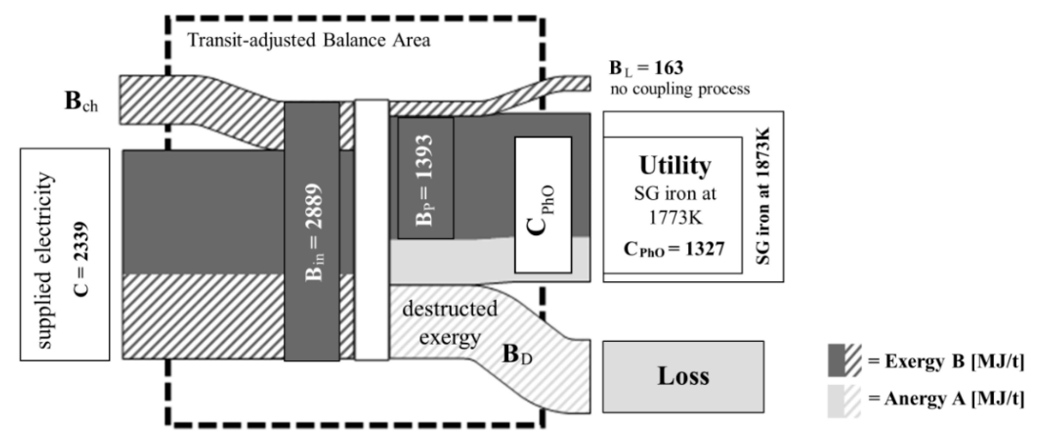
The standard chemical exergy of the inputs and outputs is calculated using the tabulated values from Szargut et al. [7]. The heat capacities and the physical and chemical exergy flows are shown in Figure 3 and Table A1 in Appendix A. The term “transit-adjusted” addresses the exergy input and output of the balance area minus the transit exergy.
The exergy of useful products BP is the SG iron-bound exergy output without the transit exergy. The exergy utility is composed of the physical and chemical exergy of the product. The melt has a temperature T2 of about 1873 K when it leaves the balance area.
The exergy loss of the induction furnace is the material-bound exergy of the exhaust air (86.1 MJ/tP), the coolant (62.2 MJ/tP), and the slag (14.9 MJ/tP). It amounts to 163 MJ/tP in total without the transit flows. The exergy loss is calculated as the sum of the physical and chemical exergy of the slag, exhaust air, and coolant minus their respective transit exergy from coolant and impurities. For example, for exhaust air, the exergy loss in MJ/t is 3.7 (ch) + 82.7 (ph)—0.3 (ch, from impurities) = 86.1. The chemical exergy of 3.4 MJ/t comes from the carbon input, which is considered as material need on the input side and material loss on the output side—in contrast to the material input of impurities, which are neither considered as a demand nor as a loss. These data can be obtained from Table A1 in Appendix A.
The exergy is supplied firstly by means of electrical energy and secondly as exergy bound in the input materials. Transit-adjusted, feeding exergy of 2889 MJ/tP enters the system of which 1393 MJ/tP leaves the system as product-bound exergy output BP without the transit exergy of the recycled metal and the stack of sheets. As the difference between transit-adjusted output and input exergy, the exergy destruction is 1327 MJ/tP. Consequently, the transit-adjusted exergy efficiency η ¯ B is 48%.
Figure 3 illustrates the exergy flows of the induction furnace in a Sankey diagram. Transit flows are separated by means of an inner system boundary. The underlying data can be found in Table A1 in Appendix A.
The Sankey diagram shows that the largest quantities of exergy pass through the balance area as transit flows. This is due to the fact that all chemical exergies are taken into account, even if they are not involved in the process. The recycled metal and the stack of sheets are liquefied in the induction furnace but only change their chemical structure insignificantly. Hence, only the physical exergy is considered within the transit-adjusted balance area in this case.
In addition to efficiency measures for reducing heat losses, the exergy balance reveals a theoretical potential of approximately 163 MJ/tP for increasing efficiency through the implementation of coupling processes. This corresponds to the unused exergy loss that is due to exhaust gas, slag, and coolant for inductor and electric.

3.2. PhO Method

Contrary to exergy analysis, the starting point for the method of PhO is the description of the PhO as the theoretical ideal reference process. As described in Section 2.3., the utility is defined as the liquid melting material with a temperature of 1773 K since this temperature is sufficient for the quality requirements based on the assumption of the ideal material composition of the input materials for the PhO. The method only considers one dimension at a time, which is energy in this study.
The theoretical minimum energy input is calculated by the enthalpy differences between the input and output substances at the respective temperature levels. SG iron at 1773 K has an enthalpy value of 1327 MJ/t [18] (p. 16). Due to an enthalpy value of zero of pure substances, the enthalpy difference is 1327 MJ/t (cf. Figure 2). This corresponds to the theoretical minimum expenditure CPhO.
The medium-frequency induction furnace is considered the most efficient furnace to achieve the defined utility, compared to cupola furnace or other induction furnaces [22] (p. 26). Hence, this technology is described for the theoretical case of the PhO. The following properties are required for the utility generated by the ideal minimum expenditure:
  • No ohmic resistances of transformer, inverter, capacitor, coil, and power lines;
  • No magnetic scattering or no magnetic resistance of the environment;
  • No iron losses of the transformer and the coil;
  • No friction due to coil vibrations (due to ideal fixing of the coil (rigid body) or friction coefficient equal to zero);
  • No heat loss of the furnace (adiabatic crucible or zero melting time).
These are technically not feasible but can be regarded as the physical limit to which the technical improvements are approaching. On the basis of this, optimization possibilities can be derived.
The electrical energy, which amounts to 2339 MJ/tP, is taken into account as the only energy input. The enthalpy of the coolant input is disregarded since it is a transit flow. The averaged efficiency of the transformer amounts to 98.5% and the one for the induction coil is 83.9%. Converter, capacitor, and power lines have an overall efficiency of 94.4% [17]. The reciprocal value equals the PhO factor of each component.
The PhO factor of the induction furnace is calculated as the ratio of real resource input C to the ideal minimum input CPhO, referring to the system boundary in Figure 1. It amounts to approximately 1.76, which means 1.76 times more energy is currently required than theoretically predicted. Thus, the theoretical energy-saving potential equals the loss, which amounts to 1012 MJ/tP. Based on our calculations, the energy analysis of the induction furnace according to the PhO method is shown in Figure 4.

3.3. Method Comparison

In this section, differences and intersections of the PhO method and exergy analysis are analyzed. The PhO is defined as the optimal, ultimate process that provides the starting point for the analysis. The exergy B, on the other hand, is a certain energy fraction that can be irreversibly converted into anergy A by exergy destruction ED. In contrast to the PhO method, the exergy analysis starts from the real process from whose analysis the theoretically avoidable losses can be derived. Thus, exergy destruction BD within the balance area and the exergy loss BL leaving the system unused become clear.
One goal of the exergy analysis and the PhO method is to reveal the physical limitations of the improvement measures. The exergetic optimum corresponds to a process that has no exergy destruction BD and no exergy loss BL. This theoretical process with no exergy losses BD and BL represents an ultimate reference process similar to the PhO. However, in this study, the exergy analysis is more precise because the chemical composition of the environment and the exergy of the material flows are taken into account.
Regarding the analysis of the induction furnace, the difference between C and Bin results from the chemical exergy of the material input of carbon (C) and SiC, which is not considered within the de PhO method in this application example. Furthermore, different minimum energy demand was derived regarding BP compared to CPhO. The difference has multiple reasons. Firstly, the PhO method assumes a physically optimal product made from ideal input materials, which results in another averaged heat capacity. Secondly, the exergy analysis regards the exergy of the product that has 100 K higher temperature than required according to the utility definition. Additionally, the product contains chemical exergy, which is disregarded by the PhO method as applied in this study. However, the most important reason is that the PhO method makes no explicit distinction between exergy and anergy. Within the PhO method, the minimum energy demand QPhO is calculated as enthalpy difference despite the entropy increase during the isobaric change of state from T1 above ambient temperature to a higher temperature [4] (p. 22). Thus, the enthalpy includes the anergy of Tamb(S2S1), which was not considered in the scope of the PhO method in this study. In this case, however, it would be important to conclude that the CPhO must have this certain composition of anergy and exergy. Since electricity, which is pure exergy, is supplied to the furnace the minimum exergy expenditure is
B m i n =   H 2 H 1 T a m b S 2 S 1 .
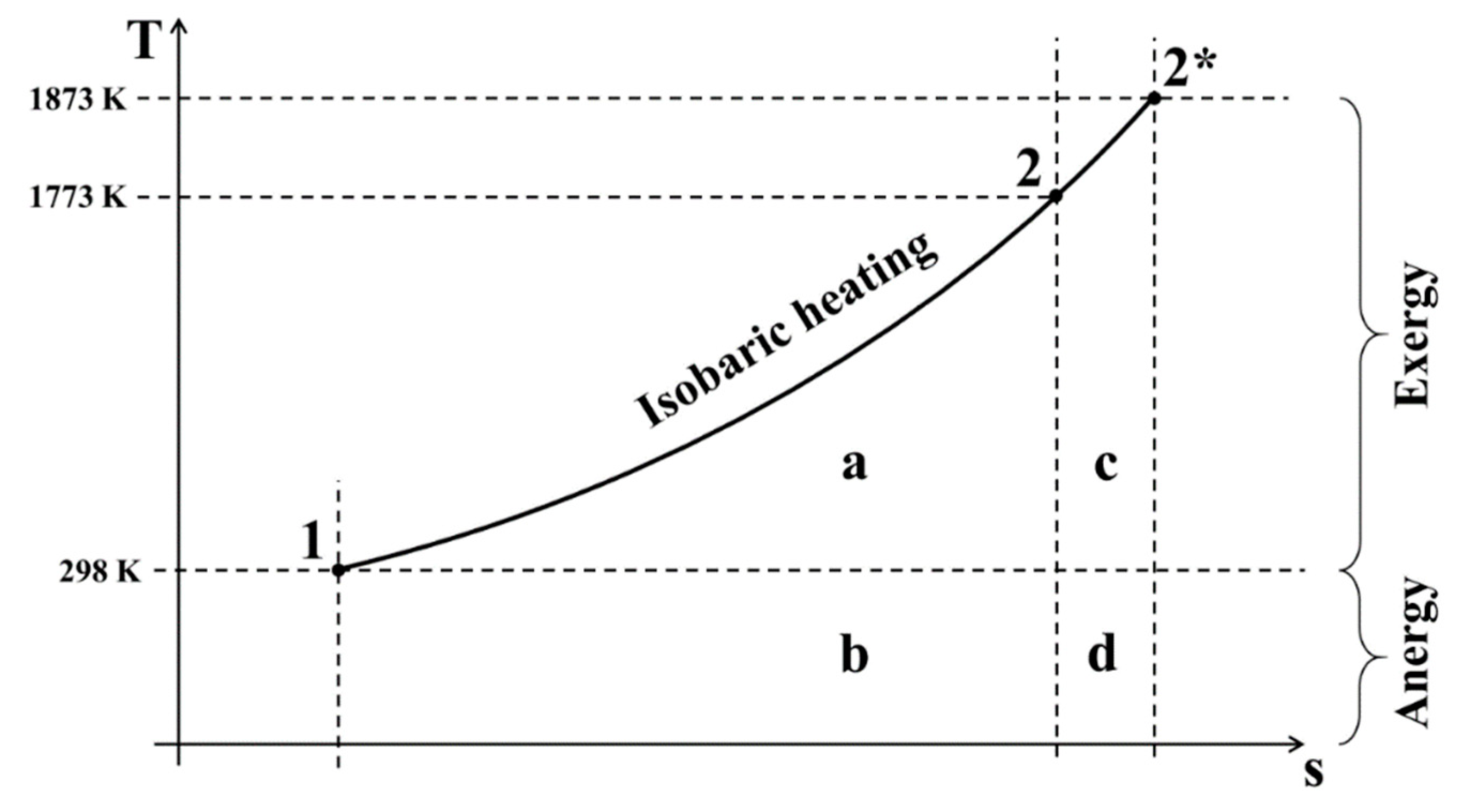
This relation is illustrated in Figure 5 by means of the T–s diagram. The areas in the diagram below the isobar are named a, b, c, and d. Since the minimum energy consumption CPhO according to the PhO method is calculated as the enthalpy difference in this study, this corresponds to the sum of the areas a and b. According to Equation (6), the minimum exergy input is the enthalpy difference of the product in state 2 to state 1 (i.e., the sum of areas a and b) minus the entropy difference multiplied by the ambient temperature (i.e., minus area b). This gives a total of (a + b) − b = a. The area a thus corresponds to the minimum exergy input in the case of PhO. Since the exergy analysis in this study is based on the real process, T2 is equal to 1873 K and the exergy in the product is equal to the sum of the two areas a and c. The differing averaged heat capacities are neglected in this context.
To sum up, these differences between exergy analysis and the PhO method with regard to the analysis of the induction furnace are shown in Figure 6 by means of a Sankey diagram.
For the process-independent comparison of the two balancing approaches, the PhO energy flows are also analyzed by considering the exergy flows, although no exergy analysis is intended according to [1,2,4]. Deviations due to chemical exergy and the difference between exergy of the product and exergetic utility are neglected.
In contrast to the exergy analysis, which considers only the exergy input as an expenditure, regarding the PhO method, anergy is in some cases considered as an expenditure or as part of the utility, e.g., the anergy fraction of the “ideal heat input QPhO” for a hot water supply. Thus, “expended” anergy Ain,exp has to be considered if it is defined by the framework condition that the energy input is supplied as heat.
Contrary to this, anergy as ambient heat is counted in some cases as “costless” ambient heat, which is used, e.g., for a heat pump. Regarding this case of a heat pump, free anergy Ain,0 enters the balance area and leaves it as anergy of the product AP in case heat is the utility.
Thus, for this comparison the anergy input Ain can be divided into the “costless” ambient anergy Ain,0 on the one hand, and the anergy expenditure Ain,exp as part of heat input on the other hand. Furthermore, in the case of heat as the utility, this utility can be described by a quantity of energy consisting of both exergy BP and anergy AP. Hence, the anergy output Aout is either the product-bound anergy AP in case of heat being the utility or, in the case of a Carnot process, emitted to the environment as Aout,exp together with the destructed exergy BD. The originally expended anergy Aout,exp leaves the system “unnoticed” and separately from the utility. In the case of the Carnot process, however, this anergy Aout,exp cannot be counted toward the losses either if the framework condition defines heat as the input and pure exergy BP as the utility. In general, the minimum energy expenditure CPhO according to the PhO method equals the sum of BP and Ain,exp. However, Ain,exp appears to be a special case.
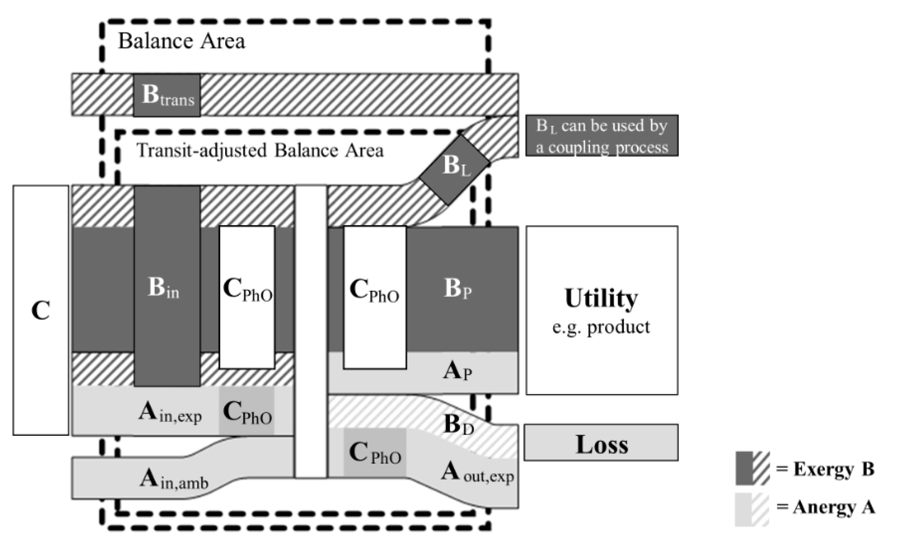
To sum up, Figure 7 shows the energy balance of an open system as a Sankey diagram. The balance is associated with exergy and anergy flows entering and leaving the system. Transit exergy Btrans is theoretically led around the balance area and therefore subtracted from the balance. The PhO method as applied in this study neglects the transit flows. Transit anergy can be neglected since ambient heat is available unlimited and has no effect on the process.
The comparison makes clear that coupling processes are possible only when the exergy loss BL is greater than zero, which is not estimated within the PhO method as long as exergy is not used as a state variable within the PhO method, as in this study. Only the exergy analysis reveals whether and to what extent the losses can be used by coupling processes. An important result is that at least the losses must be analyzed exergetically if the potential for coupling processes is to be determined.

4. Discussion

This section provides a discussion of the assumptions made and compares the results of this study with those of previous studies. Furthermore, the differences and similarities found between the exergy analysis and the PhO method are discussed.

4.1. Analysis of the Induction Furnace

The physical exergy of the SG iron of 975 MJ/t at 1873 K is first compared with literature values. This result is based on a calculated heat capacity of 0.949 kJ/kg/K as the mean slope of the enthalpy curves by Hack [18] (pp. 11–17). On the contrary, Gonzales et al. [23] report physical exergy for liquid steel of 550 MJ/t, and for hot metal, of 530 MJ/t at 1573 K, and ambient pressure by using the specific heat capacities of 0.68 kJ/kg/K and 0.71 kJ/kg/K, respectively. These values originate from Lally et al. [24] and refer to a 1010 carbon steel grade, which means the carbon content is significantly lower. Moreover, it is based on the simplifying assumption of the heat capacities being “constant functions of temperature outside of the two phase region” [24]. This may cause the deviation. Furthermore, Szargut et al. [7] (p. 113) provide a graph showing the correlation between the physical exergy of Fe–Fe3C alloys depending on temperature and mass percentage of carbon. Accordingly, the physical exergy of cast iron with 3.6% carbon content is about 770 MJ/t at 1573 K and about 900 MJ/t at 1773 K, which approximately corresponds to the values calculated in this study.
A major point for discussion regarding the exergy analysis is transit flows. It must be precisely examined which exergy flows are regarded as transit flows because this has crucial effects on exergetic efficiency. The more transit flows that are included, the higher is the calculated efficiency. Within the scope of this analysis, the majority of the chemical exergy of the input materials was treated as transit exergy since the chemical structure of these materials changes only to a minor extent. In order to reduce the uncertainty of the assumption to transit flows, we recommend regarding the exergetic efficiency and the entire exergy balance.
Furthermore, the example of the induction furnace shows the importance of the definition of the utility and the system boundary. If the utility is defined as the exergy content of the product, it will not be clear, for example, that the product is heated to a temperature of 1873 K, which is more than is physically necessary to achieve the required product quality. The foundry under consideration heats up to 1873 K to ensure a sufficiently high temperature during an unusually long retention time after the melting process. A distinction should therefore be made, where appropriate, between the exergy utility and the exergy of the product. Another difference to be further analyzed is whether the system undergoes exergy loss or destruction. In addition, the definition of the system boundaries and framework conditions is crucial. If the balance area would be extended to the finished casting at ambient temperature, waste heat in the PhO could be completely recovered or used externally. In this case, it could be argued that the minimum effort would be 0 MJ/t due to recovery or allocation.
For a more comprehensive comparison between the two methods regarding more technologies and processes, further investigation is required. Among others, a more detailed study of the handling of waste heat and cooling of initially heated materials as the complement to the induction furnace would be helpful since the utility definition and framework conditions are not entirely clear.

4.2. Method Comparison

Although both methods show the physical limits of efficiency improvements, some differences became apparent regarding the evaluation of inventoried flows, the calculation of minimum expenditure, and the maturity and complexity of the methods. Accordingly, there are different areas of application for the two methods.
The PhO method is intended for the separate evaluation of different levels of inventoried flows. This concerns energy, resources, and information [2] (p. 56). In this context, however, no approach has yet been provided as to how the different levels can be evaluated against each other. A combined approach to evaluate energy and material efficiency is so far only possible by means of exergy analysis.
Moreover, the PhO method does not explicitly distinguish between exergy and anergy. Describing the minimum energy input as “ideal heat input” calculated by the enthalpy difference, as intended in the VDI guideline, is less informative than an exergy calculation since the energy quality does not become clear and any heat could theoretically be provided by means of upgrading anergy by pure exergy.
The application of the PhO method in this study comprises approximately the thermodynamic and exergy correlations but neglects the chemical composition of the material flows and the environment. In some cases, this can lead to wide variations from the exergy analysis. In this study, the exergy analysis provides a more precise result regarding energy and material flows. An exergy analysis to be recommended if chemical exergy is a crucial factor and chemical material flow data is available. In addition, it is advantageous in order to evaluate work and heat uniformly. Moreover, the theoretical potential for coupling processes can be identified by distinguishing between exergy destruction and exergy loss.
The calculation of the minimum effort is generally based on the utility definition. In the case of the exergy analysis, we define the utility as the exergy of the product according to Szargut et al. [7]. Instead, the PhO method considers the benefit of the reference product as the SG iron at 1873 K since among others Dötsch [10] reports that this is usually sufficient. These different assumptions regarding the utility definition should be considered. The exergy analysis could also be performed by defining the utility as the exergy of the SG iron at 1773 K under PhO conditions since the exact description of utility and boundary conditions are not methodologically specified.
In order to determine the theoretical limit value of the expenditure for the defined utility using the PhO method, it must be possible to quantify the utility and allocate a minimum amount of resources. As the exergy analysis is mostly based on a real process, the analysis can be performed for every process. However, the exergy efficiency can only be calculated if the exergy utility is quantifiable.
Furthermore, it should be considered that the PhO method was developed by Volta [1] a few years ago, and the development of guidelines and systematics is not yet finished. A draft for a new guideline of the Association of German Engineers (VDI) is currently available [4]. The exergy analysis is well developed and mature. Moreover, the term optimum can be misleading because in the context of the PhO method it does not describe the compromise of two opposing parameters but rather the unreachable limit value or ideal. Another important difference between the two methods is the complexity of the methods. Therefore, the time required to carry out the PhO method in this study is lower than for the exergy analysis. On the other hand, the results can be less precise as long as exergy is not used as a state variable within the PhO method, as in this study.
An advantage of the PhO method compared to the exergy analysis is that fluctuations in ambient temperature and pressure can be taken into account more easily as long as the energy is used as a state variable. This can result in a temperature or pressure-dependent value for the PhO, enabling the efficiency to be measured using the PhO factor independently of these fluctuations. The consideration of tabulated chemical exergy that always refers to standard ambient conditions makes this more difficult within the exergy analysis.
Either way, both methods contribute significantly to the appropriate target definition for efficiency measures. This will make it possible to identify at an early stage the extent of the necessity for complementary measures to make production more environmentally friendly, e.g., by using renewable energies. For example, induction furnaces could be operated almost entirely with electricity from renewable energy sources [25].

5. Conclusions and Outlook

Due to the interactions between the individual efficiency measures, the total energy saving potential cannot be derived from the individual potentials. A crucial advantage of the limit value-oriented assessment methods is that the theoretical potential can be shown and used to estimate the current technical potential. Regarding the energy flows, the induction furnace under consideration currently requires 1.76 times more energy than theoretically predicted to melt SG iron. Similarly, the exergy analysis results in an exergy efficiency of 48%, which, however, depends strongly on the definition of transit exergy.
The comparison of the two methods demonstrates that the exergy analysis is much more complex and accurate than the PhO method regarding the assessment of material flows, especially in the case of chemical reactions taking place and as long as exergy is not used as a state variable within the PhO method, as in this study. The material and energy flows can be evaluated in combination by quantifying by means of exergy units. The chemical exergy of the material flows is also taken into account in relation to the chemical composition of the environment. With the PhO method as applied in this study—e.g., apart from the calorific values—the chemical exergy of the materials toward the environment is not taken into account due to the chemical composition of the environment being neglected. By distinguishing between exergy destruction and exergy loss, the theoretical potential for coupling processes can be identified by means of exergy analysis. Only with exergy analysis, the exergy content of the losses and irreversibility to be avoided in the system become clear. In some cases, it should be considered which exergy fraction must be included in the minimum energy input according to the PhO method. For example, the “ideal amount of heat” for heating cannot be ambient heat but must contain a certain amount of exergy, which only becomes clear by means of the exergy analysis.
Depending on the framework conditions and the desired level of detail of the efficiency assessment, it must be decided which method with what accuracy is to be applied. If material and energy are to be evaluated in combination, an exergy analysis can be used for more extensive investigations. The calculation of the minimum energy requirement can significantly support the appropriate definition of the efficiency goals. Both methods can be suitable for this purpose.
In the context of the Paris Climate Agreement, increasing resource efficiency is regarded as an important measure. Limit-value-oriented assessment methods can contribute to determining the extent to which it is theoretically possible to limit the climate impact of increasing resource demand by increasing efficiency. These methods demonstrate that this is only possible to a limited extent, and the necessity for further measures such as renewable energy, sufficiency, and consistency options can be quantified. Both the PhO method and the exergy analysis can make a decisive contribution to this strategy. Depending on the goal and scope, there are different areas of application for the two methods.

Author Contributions

Conceptualization, P.M.W., P.R., and J.W.; methodology, P.M.W., P.R., and J.W.; validation, P.M.W.; formal analysis, P.M.W.; investigation, P.M.W.; data curation, P.M.W. and J.W.; writing—original draft preparation, P.M.W.; writing—review and editing, P.M.W. and P.R.; visualization, P.M.W.; supervision, P.R. and J.W.; project administration, P.R.; funding acquisition, P.M.W. and P.R. All authors have read and agreed to the published version of the manuscript.

Funding

This research was funded by the Graduate and Research School for Energy Efficiency Stuttgart, GREES PhD scholarship and the Open Access Publication Fund of the University of Stuttgart.

Institutional Review Board Statement

Not applicable.

Informed Consent Statement

Not applicable.

Data Availability Statement

No new data were created or analyzed in this study. Data sharing is not applicable to this article.

Acknowledgments

The authors gratefully acknowledge the support of Bosch Energy and Building Solutions GmbH, in particular for enabling the data collection.

Conflicts of Interest

The authors declare no conflict of interest. The funders had no role in the design of the study, in the collection, analyses, or interpretation of data, in the writing of the manuscript, or in the decision to publish the results.

Nomenclature

AbbreviationsSubscripts
PhOphysical optimumambambient (reference state, components)
PIOTphysical input-output tablechchemical
SG ironspheroidal graphite cast ironDinternal loss, destruction
VDIVerein Deutscher Ingenieureelrelated to electricity
Symbols exp
Aanergy [J]icomponent, parameter
Bexergy [J]ininput
Camount of a resource (e.g., energy [J])kinkinetic
cheat capacity [kJ/(kgK)]Lexternal loss
ffactor [−]magrelated to magnetism
Henthalpy [J]mechmechanical
ppressure [Pa]outoutput
Qheat [J]Pproduct
Sentropy [J/K]phphysical
Ttemperature [K]PhOphysical optimum
Vvolume [m3]potpotential
Wwork [J]ththermal
xmass fraction [kg/kg]transtransit
ymole fraction [mol/mol]
ζexergy efficiency [%]

Appendix A

Table A1 presents the data and relations of the exergy analysis. The data on chemical exergy originates from Szargut et al. [7]. Moreover, the data on heat capacity are obtained from the VDI Heat Atlas [21], except the heat capacity of SG iron. The mass and energy flows and temperatures are listed in the physical input-output table in Section 2.3 (cf. Table 2).
Table A1. Exergy analysis of the induction furnace. The top line of each section is the sum of the different chemical components, e.g., the stack of sheets consists of iron (F) and carbon (C).
PIOTChemical ExergyPhysical ExergyTransit-Adjusted
Parameter iValue xiMolar massbch,I [kJ/mol] [7]Bch [MJ/tP]T [K]cp [kJ/kgK]Bph [MJ/tP]Bch,trans [MJ/tP]Bph,trans [MJ/tP]
InputElectrical Energy2339 MJ
Stack of Sheets358.0 kg 2511 0 0
Fe (α)354.4 kg55.853762389
C3.6 kg12.01410122
Recycled metal625.0 kg 4881 0 0
Fe (α)590.6 kg55.85376.43980
C (graphite)23.1 kg12.01410.3634
Si11.2 kg28.09854.6266
Alloying materials17.1 kg 546 05460
C (graphite)7.5 kg12.01410.3257
SiC (hexag.)9.6 kg40.101204.6290
Impurities20.9 kg 20.0 000
SiO2 (quartz)11.0 kg60.097.91.4
Al2O3 (α cor.)2.9 kg101.96200.45.7
CaO6.5 kg56.08110.212.8
Fe2O3 (hem.)0.6 kg159.6916.50.1
Intake Air6300 kg 0 000
dry air6206 kg1.29
H2O (gaseous)94.5 kg18.02
Coolant Inductor5811 kg18.020.92903134.19900
Coolant Electric5505 kg18.020.92753074.19300
OutputLiquid SG iron1000 kg 781018730.949975.0418975
Fe (α)945 kg55.85376.46369
C (graphite)37 kg12.01410.31015
Si18 kg28.09854.6426.4
Slag20.0 kg 19.71573 14.8015
SiO2 (amorph.)10.7 kg60.097.91.415730.988.2
CaO6.5 kg56.08110.212.815730.904.6
Al2O3 (α cor.)2.8 kg102200.45.515730.962.1
Exhaust Air1.0 kg 3.7393 82.73.483
Fe2O3 (hem.)0.6 kg159.716.50.13930.710.0
SiO2 (amorph.)0.3 kg60.097.90.03930.860.0
C (graphite)0.1 kg12.01410.33.43931.110.0
Al2O3 (α cor.)0.1 kg102200.40.23930.930.0
dry air6206 kg 0.03931.0077.8
H2O (gaseous)94.5 kg18.029.549.83934.195.0
Coolant Inductor5811 kg18.020.9290.33404.1965.8057
Coolant Electric5505 kg18.020.9275.03134.198.405
Exergy Destr. BD1329 MJ 781018730.949975.0418975

References

  1. Volta, D. Das Physikalische Optimum als Basis von Systematiken zur Steigerung der Energie- und Stoffeffizienz von Produktionsprozessen. Ph.D. Thesis, Universitätsbibliothek Clausthal, Technische Universität Clausthal, Clausthal-Zellerfeld, Germany, 2014. [Google Scholar]
  2. Keichel, C. Methode der Grenzwertorientierten Bewertung. Ph.D. Thesis, Universitätsbibliothek Clausthal, Technische Universität Clausthal, Clausthal-Zellerfeld, Germany, 2017. [Google Scholar]
  3. Beckmann, N. Wechselwirkungsanalyse Zwischen dem Physikalischen Optimum, dem Betriebswirtschaftlichen Optimum und dem Carbon-Footprint-Optimum (PhO-BwO-CFO). Ph.D. Thesis, Universitätsbibliothek Clausthal, Technische Universität Clausthal, Clausthal-Zellerfeld, Germany, 2017. [Google Scholar]
  4. Sankol, B.; Keichel, C.; Volta, D.; Pauksztat, A.; Kohn, D.; Kretschmer, L.; Meyer, S.; Girbig, P.; Kastner, H.-J. (Eds.) Verein Deutscher Ingenieure. Bewertung von Energie- und Stoffeffizienz Methodische Anwendung des Physikalischen Optimums; Beuth Verlag GmbH: Berlin, Germany, 2019; ISC 27.015 (4663-1). [Google Scholar]
  5. Szargut, J. International progress in second law analysis. Energy 1980, 5, 709–718. [Google Scholar] [CrossRef]
  6. Gutowski, T.G.P.; Sekulić, D.P. Thermodynamic Analysis of Resources Used in Manufacturing Processes. In Thermodynamics and the Destruction of Resources; Bakshi, B.R., Sekulić, D.P., Gutowski, T.G.P., Eds.; Cambridge University Press: Cambridge, UK, 2011; ISBN 9780511976049. [Google Scholar]
  7. Szargut, J.; Morris, D.R.; Steward, F.R. Exergy Analysis of Thermal, Chemical and Metallurgical Processes; Hemisphere Publ. Corp: New York, NY, USA, 1988; ISBN 9780891165743. [Google Scholar]
  8. Fratzscher, W.; Brodjanskij, V.M.; Michalek, K. Exergie. Theorie und Anwendung, 1st ed.; Deutscher Verlag für Grundstoffindustrie: Leipzig, Germany, 1986; ISBN 3-342-00091-0. [Google Scholar]
  9. Riedl, K. Exergetische und Exergoökonomische Bewertung von Verfahren der Energie- und Stoffwandlung. Ph.D. Thesis, Martin-Luther-Universität Halle-Wittenberg, Merseburg, Germany, 2007. [Google Scholar]
  10. Dötsch, E. Induktives Schmelzen und Warmhalten. Grundlagen, Anlagenaufbau, Verfahrenstechnik, 3rd ed.; Vulkan Verlag: Essen, Germany, 2019; ISBN 9783802731075. [Google Scholar]
  11. Dötsch, E. Induktionsofentechnologie und Energieeffizienz. GIESSEREI 98 2011, 6, 158–170. [Google Scholar]
  12. ETSU. Efficient Melting in Coreless Induction Furnaces. Good Practice Guide 50. 2000. Available online: https://lists.man.lodz.pl/pipermail/odlew-pl/2012/10/att-0003/guide_coreless_induction_furnaces.pdf (accessed on 12 October 2020).
  13. Neumann, F. Gußeisen. Schmelztechnik, Metallurgie, Schmelzbehandlung, 2nd ed.; Expert-Verl.: Renningen-Malmsheim, Germany, 1999; ISBN 3816917283. [Google Scholar]
  14. Schwanke, W. Schmelzen in Hochleistungsinduktionsöfen. In Elektrische Prozeßwärme für Aluminium, Gußeisen, Stahl: Tagung Essen, July 1993, 1st ed.; VDI, Ed.; VDI-Verl.: Düsseldorf, Germany, 1993; pp. 97–100. ISBN 3-18-091057-7. [Google Scholar]
  15. Wenzel, P. Exergetische Analyse und Physikalisches Optimum zur Bewertung und Steigerung der Ressourceneffizienz am Beispiel Eines Mittelfrequenzofens. Master‘s Thesis, Universität Stuttgart, Stuttgart, Germany, 2019. [Google Scholar]
  16. Frenzel, P. Bewertung von Syntheserouten auf Basis von Exergiebilanzen. Ph.D. Thesis, Technische Hochschule Aachen, Aachen, Germany, 2014. [Google Scholar]
  17. Trauzeddel, D. Spezielle Anwendungen der Induktiven Schmelz- und Gießtechnik. Einsatzgebiete—Anlagenbau—Prozesstechnik, 1st ed.; Vulkan: Essen, Germany, 2018; ISBN 978-3-8027-3093-1. [Google Scholar]
  18. Hack, K. Stoffwerte von Metallen und Berechnung von Wärmebilanzen. In Praxishandbuch Thermoprozess-Technik, 1st ed.; Starck, A.V., Mühlbauer, A., Kramer, C., Eds.; Vulkan-Verl.: Essen, Germany, 2003; ISBN 3-8027-2923-4. [Google Scholar]
  19. Trauzeddel, D.; Otto Junker GmbH, Simmerath, Germany. Personal communication, 6 May 2019.
  20. Neumann, F.; Schneider, W.-D.; Herfurth, K. Der Schmelzprozess für Eisenguß (GG/GGG/GT) aus der Sicht der Umwelt- und Klimabelastung in Zusammenhang mit dem Energieverbrauch. In Elektrische Prozeßwärme für Aluminium, Gußeisen, Stahl: Tagung Essen, July 1993, 1st ed.; VDI, Ed.; VDI-Verl.: Düsseldorf, Germany, 1993; ISBN 3-18-091057-7. [Google Scholar]
  21. Verein Deutscher Ingenieure. VDI-Wärmeatlas, 11th ed.; Springer: Berlin/Heidelberg, Germany, 2013; ISBN 978-3-642-19980-6. [Google Scholar]
  22. Svehla, J.; Krutzler, T.; Schindler, I. Stand der Technik der Österreichischen Gießereien. Gesetzliche Rahmenbedingungen, Technische Möglichkeiten und Gießereibetriebe in Österreich. 2012. Available online: https://www.umweltbundesamt.at/fileadmin/site/publikationen/REP0389.pdf (accessed on 12 October 2020).
  23. Gonzalez Hernandez, A.; Paoli, L.; Cullen, J.M. How resource-efficient is the global steel industry? Resour. Conserv. Recycl. 2018, 133, 132–145. [Google Scholar] [CrossRef] [Green Version]
  24. Lally, B.; Biegler, L.; Henein, H. Finite difference heat-transfer modeling for continuous casting. MTB 1990, 21, 761–770. [Google Scholar] [CrossRef]
  25. Bosse, M.; Frost, E.; Hazrat, M.; Riemeier, J.-M.; Wolff, H. Ermittlung von Branchenspezifischen Potentialen zum Einsatz von Erneuerbaren Energien in Besonders Energieintensiven Industriesektoren am Beispiel der Gießerei-Industrie. UBA-FB 00. 2013. Available online: https://www.bmu.de/fileadmin/Daten_BMU/Pools/Forschungsdatenbank/fkz_3712_44_347_erneuerbare_energien_bf.pdf (accessed on 12 January 2020).
Figure 1. Process structure based on [10] (p. 22) and system boundaries for this study.
Energies 14 01621 g001
Figure 2. Enthalpy curves of carbon (C), iron (Fe), silicon (Si), ferrosilicon (FeSi), silicon carbide (SiC), and SG iron as a function of temperature, based on [18] (pp. 11–17).
Energies 14 01621 g002
Figure 3. Sankey diagram of the exergy flows of the induction furnace melting SG iron.
Energies 14 01621 g003
Figure 4. Sankey diagram of the energy flows of the induction furnace melting SG iron according to the physical optimum (PhO) method.
Energies 14 01621 g004
Figure 5. Simplified T–s diagram of the isobaric heating of SG iron from T1 > Tamb and illustration of the minimum energy demand CPhO as a plus b for heating to 1773 K (state 2) at PhO and the exergy of the product BP as a plus c for heating to 1873 K (state 2*) as in the real process.
Energies 14 01621 g005
Figure 6. Correlations between exergy analysis and PhO method regarding the exergy and anergy flows [MJ/t] of an induction furnace.
Energies 14 01621 g006
Figure 7. Energy balance of an open system examined by both exergy analysis and PhO method. While the PhO method regards the real energy expenditure C, the ideal minimum energy input CPhO and losses and coupling processes, the exergy analysis goes further by explicitly dividing between exergy and anergy and, if necessary, considering transit flows.
Energies 14 01621 g007
Publisher’s Note: MDPI stays neutral with regard to jurisdictional claims in published maps and institutional affiliations.