Article

Analysis of the Head of a Simulation Crash Test Dummy with Speed Motion

1
Department of Automotive Engineering and Transport, Kielce University of Technology, Avenue Tysiąclecia Państwa Polskiego 7, 25-314 Kielce, Poland
2
Institute of Vehicles, Warsaw University of Technology, 02-524 Warsaw, Poland
3
Globtrak Polska Sp. z.o.o., ul. Wincentego Witosa 65/2, 25-561 Kielce, Poland
*
Author to whom correspondence should be addressed.
Energies 2021, 14(5), 1476; https://doi.org/10.3390/en14051476
Submission received: 15 January 2021 / Revised: 24 February 2021 / Accepted: 2 March 2021 / Published: 8 March 2021
(This article belongs to the Special Issue Vehicle and Traffic Safety)

Abstract

:
The article presents a model of an anthropometric dummy designed for low velocity crash tests, designed in ADAMS. The model consists of rigid bodies connected with special joints with appropriately selected stiffness and damping. The simulation dummy has the appropriate dimensions, shape, and mass of individual elements to suit a 50 percentile male. The purpose of this article is to draw attention to low speed crash tests. Current dummies such as THOR and Hybrid III are used for crash tests at speeds above 40 km/h. In contrast, the low-speed test dummy currently used is the BioRID-II dummy, which is mainly adapted to the whiplash test at speeds of up to 16km/h. Thus, it can be seen that there is a gap in the use of crash test dummies. There are no low-speed dummies for side and front crash tests, and there are no dummies for rear crash tests between 16 km/h and 25 km/h. Which corresponds to a collision of a passenger vehicle with a hard obstacle at a speed of 30 km/h. Therefore, in collisions with low speeds of 20 km/h, the splash airbag will probably not be activated. The article contains the results of a computer simulation at a speed of 20 km/h vehicle out in the ADAMS program. These results were compared with the experimental results of the laboratory crash test using volunteers and the Hybrid III dummy. The simulation results are the basis for building the physical model dummy. The simulation aims to reflect the greatest possible compliance of the movements of individual parts of the human body during a collision at low speed.

1. Introduction

Anthropometric dummies are specialized research devices that simulate both dimensions, weight proportions, and joints in the human body [1,2]. Dummies are used by vehicle manufacturers and aircraft to predict potential human injuries in an accident. Current crash test dummies have built-in sensors to record data such as impact speed, crush force, bending, torque, and crash braking pressure. Anthropometric dummies are cataloged by purpose [3,4,5]. Other dummies are used for the rear, side, and front tests. Moreover, they are tailored to a specific test in such a way as to collect as much information as possible. Therefore, the side test dummies have the upper limbs removed, which could interfere with the measurements during a crash. First of all, it should be noted that dummies are used to increase security [6,7].
Research issues concerning the protection of the driver and passengers of passenger vehicles against the consequences of any road collisions belong to the issues of impact biomechanics. An important element is the choice of the method used as well as the criteria for assessing the risk of sustaining an injury [8,9]. It should be noted that the result of the complicated nature of the loads acting on the driver or passenger during a collision is the main reason for the model testing of the applied vehicle passive safety systems. In this case, there are two types of model analyzes [10,11,12]:
  • Computer simulation tests that are performed in simulation programs with the use of virtual models representing experimental dummies,
  • experimental crash-test studies that are performed using material human models reflecting human behavior during a collision.
Experimental research is characterized by high testing costs, which significantly reduces the frequency of testing. The present times associated with sudden and rapid technological growth contribute to the increased popularity of simulation research. This type of research is characterized by [12,13,14]:
  • Low costs of building simulation models,
  • ease of conducting research on virtual models.
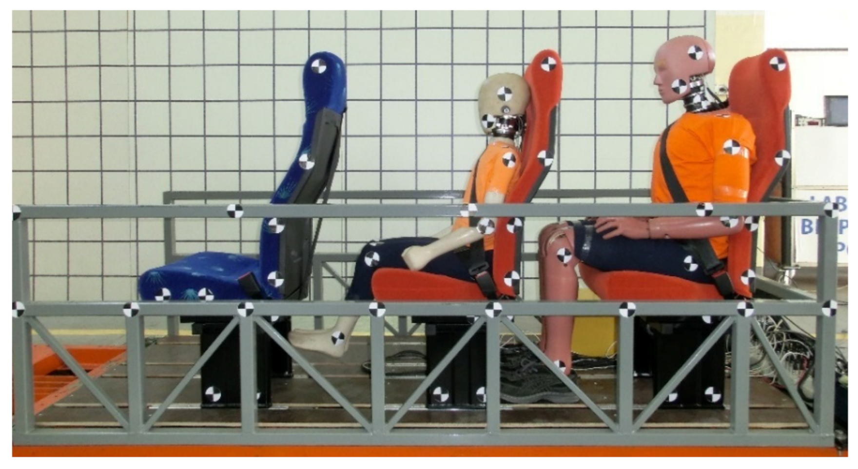
The process of correlating the results of computer simulation tests with the use of virtual manikins is called validation. The validation is to ensure that the results obtained with the use of the simulation model reflect to some extent the physical model [15,16]. On the other hand, the process of creating a simulation model requires discretization of geometry, appropriate selection of elements, defining connection elements, selection of material specifications and its physical properties, as well as knowledge of loading conditions. In addition, the selection and determination of all the above variables and parameters significantly affects the accuracy and correctness of the simulation result. Therefore, mechanical engineering in the field of modeling reliable models of anthropometric dummies can only be verified by comparing the results with actual crash tests [17,18]. Figure 1 shows the THOR anthropometric dummy, both in the real form (Figure 1a) and in the simulation form (Figure 1b), intended for frontal crash tests.
Crash test dummies consist of the spine element assemblies, the head assembly, the spine assembly, the thoracic assembly, the lower limb assembly, and the upper limb assembly. The ideal structural design of an anthropometric crash test dummy assumes a simple structure that does not require frequent calibration, while maintaining high durability and repeatability of results [19,20,21]. Currently, in the case of frontal collisions, the most advanced dummy is the THOR [19,20]. Its structure is similar to the human body. It has a developed spine with flexible joints in both the thoracic and lumbar sections. Its predecessor and competitor is the Hybrid III dummy, which is used all over the world in crash tests. It was on its basis that the side and rear collision dummies were created [21]. Hybrid III dummies have a high rate of compatibility with the human body. Research on the behavior of dummies during crash tests led to the development of an assessment of head, face, chest, abdomen, lower limb, and upper limb injuries, which are used by all countries around the world [21,22,23]
Crash tests of various types of security systems aimed at increasing passenger safety require significant financial and time expenditure [21,24,25]. Therefore, simulations are performed first. The simulation programs of anthropometric manikins include such programs as: Madymo, Dytran, Dassault Systèmes SIMULIA, ANSYS Engineering Simulation, SIMPACT Caterham Super 7, MSC Software ADAMS [26,27]. These programs allow you to perform simulated crash tests with minimal financial burden. Crash tests are carried out only after collecting the appropriate amount of data confirming the effectiveness of the simulation tests. The demand for simulation programs and computer simulations before experimenting influences the development of specialized software networks [28,29,30].
When reviewing the literature, it should be noted that simulation dummies are also available for lateral, frontal, and rear tests. The simulation dummies are a reflection of the existing anthropometric dummies [18,31]. Child simulation dummies are also available. They are designed to assess the safety of vehicles and child seats or booster cushions [32,33]. Figure 2 shows the children’s simulation dummies. The simulation dummies are intended for the same crash tests as their physical counterparts, because before performing a given experiment, simulation tests should first be carried out, which are less expensive for experimental tests [18,34].
The development of technology and the growing popularity of simulation programs resulted in an increasing interest in virtual crash tests. The article [35] presents a simulation model of a person sitting in a wheelchair. This model can be used for wheelchair crash response testing or for assessing the effect of various factors on the safety of passengers in a collision. However, the articles [36,37,38] present simulations of crash tests aimed at increasing the passive safety of a passenger vehicle. The articles [39,40] present simulations of crash tests with the use of airbags. These simulations are designed to reduce the failure rate of the airbag system, because if the airbag is deployed in inappropriate conditions, it may cause bone injuries and fractures. The articles [41,42,43] present the use of computer simulation to analyze the injuries of rear seat passengers in a frontal collision. These studies showed that a suitable belt load limiter could reduce dummy injuries. On the other hand, in [44], simulation tests were used to develop a system for restraining bus passengers during emergency braking. These simulation studies have shown that three-point seat belts can better protect the passenger, and that increasing the angle of the airbag can reduce the amount of injury to passengers.
Low speed crash tests are used to test the strength of vehicle bumpers, and they are performed at speeds of 10 km/h and 5 km/h [45]. These tests do not include the study of the movement of the individual parts of the dummy’s body. Moreover, it should be noted that in the literature, there are scientific studies aimed at determining the minimum speed at which permanent damage to the human body occurs. Only volunteers are used in tests at speeds of up to 20 km/h. Dummies for such tests are not constructed [46,47,48].
Therefore, it should be noted that the current anthropometric dummies are constantly being improved and modified. An ideal dummy should be highly resistant to damage during crash tests and highly reliable compared to the human body [49,50]. Since the development of the first crash test dummy, it was known that the dummy could not be used for all types of crash tests. Therefore, a division into rear, side, and front crash test dummies was created. The first side test dummies, such as EUROSID 1, BIOSID, were developed in 1989, while the BioRID side test dummy was developed in 2000 by engineers from General Motors and NHTSA [17,51]. The dummy was quickly upgraded to the BioRID II version. The new version of the rear crash test dummy was mainly used for the Whiplash tests at speeds up to 16 km/h. A characteristic feature of this dummy is an extensive spine consisting of the same number of vertebrae as a human. In contrast, the side test dummies were devoid of upper limbs, which could interfere with data collection during the crash test [51,52,53].
Most of the constructed anthropometric dummies have their counterparts in a digital version. Simulation dummies have very well correlated components and subassemblies with the human body [54,55]. Thanks to the development of simulation dummies, it was possible to compare physical dummies with simulation dummies and with volunteers. The first simulation dummies such as BIOSID or Hybrid III have been validated, and their authors assure that the models are able to predict injuries that may occur in a vehicle accident [56,57]. However, it should be noted that the current anthropometric dummies are used for specific crash tests. These tests are characterized by a specific speed and angle of the vehicle hitting an obstacle. Therefore, there is no anthropometric dummy that could be used for any type of crash test using low speeds [58,59].

2. Research Object

The model of a physical-point crash test dummy is a set of interrelated lumps with adequate damping and stiffness. Each element in the construction of a dummy has the appropriate shape and mass. All elements of the dummy are connected with each other by means of elaborate joints that reflect the range of human body movement. The model of the simulation dummy was made in the MSC Adams program [44,60]. This program examines the dynamics of the movement of the various parts of the dummy’s body. At the same time, it allows the transformation of a rigid body into a flexible model using the finite element method. The program environment makes it possible to modify and change the parameters of individual dummy elements. Moreover, it allows for obtaining information on the exact position of all parts of the dummy’s body at a given moment in time and then presenting them in a graphical manner. The following assumptions were made for the construction of the mathematical model of the anthropometric dummy:
  • System of rigid bodies.
  • Known dimensions, masses, and moments of inertia.
  • Model in which the movement takes place in three-dimensional space.
  • Connections of solids using hinges.
  • The only force acting on the system is the initial speed Vx (chair speed).
  • Belts and seat modeled on the basis of experimental research.
The dummy is designed in the manner of the Hybrid III manikin representing the 50th percentile male. It consists of 17 elements connected by joints. Table 1 shows the mass of the individual body parts of the designed dummy. The dummy was placed on the vehicle seat. The seat is made of one block with appropriately selected stiffness and damping characteristics. Figure 3 shows a simulation dummy designed in the MSC Adams program.
The MSC ADAMS program allows you to create and connect individual dummy solids using complex joints imitating joints. In addition, ADAMS allows you to introduce restrictions related to the movement of individual elements, select the appropriate articulation, and the number of degrees of freedom.
The simulation results of the crash test with the dummy carried out for the speed of 20 km/h were compared with the results of the experiment with the Hybrid III dummy at the same speed. Moreover, in order to check the reliability of the results, they were compared with the results of an experimental crash test in laboratory conditions with the participation of volunteers. An experimental crash test using the Hybrid III dummy was carried out at the Automotive Industry Institute in Warsaw [48]. The experimental test stand consists of a trolley to which a vehicle seat with a dummy is attached. The trolley is accelerated to a speed of 20 km/h using flexible ropes with a total length of 25 m. The expected speed is obtained by pulling the rope cart to a certain length. Releasing the ropes causes the trolley to move in a chaotic manner, which is braked with the help of 60 cm polyurethane sleeves. The experiment with a Hybrid III dummy representing a 50th centile male was recorded with a high-speed Phantom V310 camera at 600 frames/second [43,48]. Figure 4 shows the test stand located at the Automotive Industry Institute in Warsaw.
Experimental test conditions were replicated in MSC Adams. The computer simulation uses a built-in software camera operating at 2500 frames per second. The duration of the simulation was 5 s. The seat with the dummy was accelerated from zero to the assumed speed. In the next stage, the chair was moved by the force of inertia for 2 s, and then it was decelerated to zero. Braking the vehicle seat simulates a collision with a stationary obstacle. Figure 5 shows a simulation of the dummy’s movement at appropriate times. The simulation dummy was equipped with seat belts modeled as linear Kelvin-Voigt susceptibility elements. Due to the accuracy of displacements of individual parts of the dummy’s body, the seat belts were not visible during the simulation.
Experimental tests with the use of volunteers were carried out in compliance with all safety standards on a test stand intended for crash tests at low speed. The stand for simulation testing of dynamic stress, especially in the driver’s safety elements, was submitted for protection at the Patent Office of the Republic of Poland on 27 May 2019 under the number P.430055 [60]. An experimental crash test was carried out in the laboratory of motor vehicles and tractors at the Kielce University of Technology. The stand consists of a 10m long track along which a vehicle seat moves. At the end of the track, there are shock absorbers that simulate a collision with a stationary obstacle. The speed of the collision depends on the road length and the track gradient. The vehicle seat is on rollers that allow it to move freely along the tracks of the station. The measurement takes place when the electro valve is released, which keeps the chair with the dummy or the volunteer at a given height. Measurements on the experimental stand were recorded with a high-speed Phantom camera at 2500 frames per second. Figure 6 shows the view of the crash test stand at low speeds.
Experimental studies with the participation of volunteers were performed on a sample of 20 people. The results of the experimental studies were averaged. The averaged dimensions of the people participating in the experiment are presented in Table 2. The averaged results showed a picture of a person representing the 50th percentile of the population.
Comparative tests of the low speed crash test dummy were conducted with the Hybrid III dummy and volunteer. It should be noted that in the case of the test with the Hybrid III dummy and volunteer, other vehicle seats were used, therefore the stiffness of the backrest and the headrest are different. Moreover, the designed vehicle seat in the ADAMS program consists of a single body having the same stiffness, which makes it difficult to compare the head displacement of the simulation dummy with the Hybrid III and volunteer.

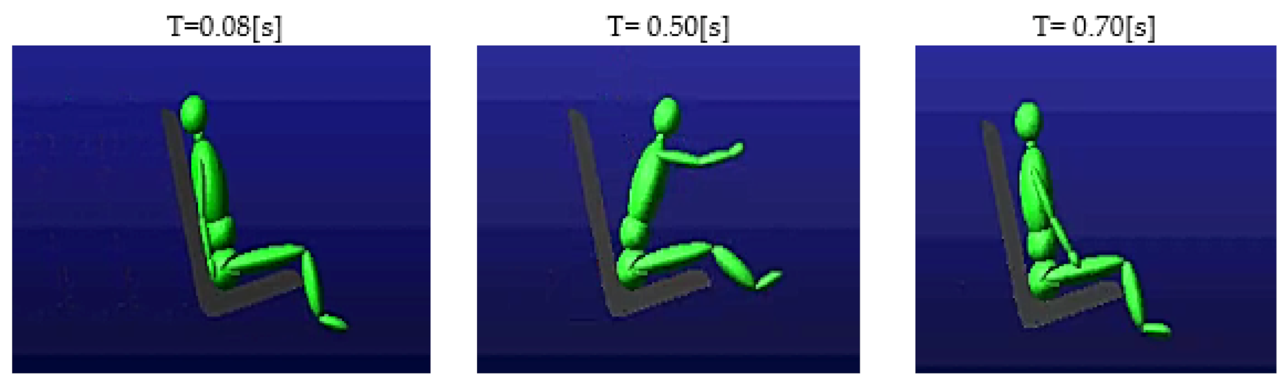
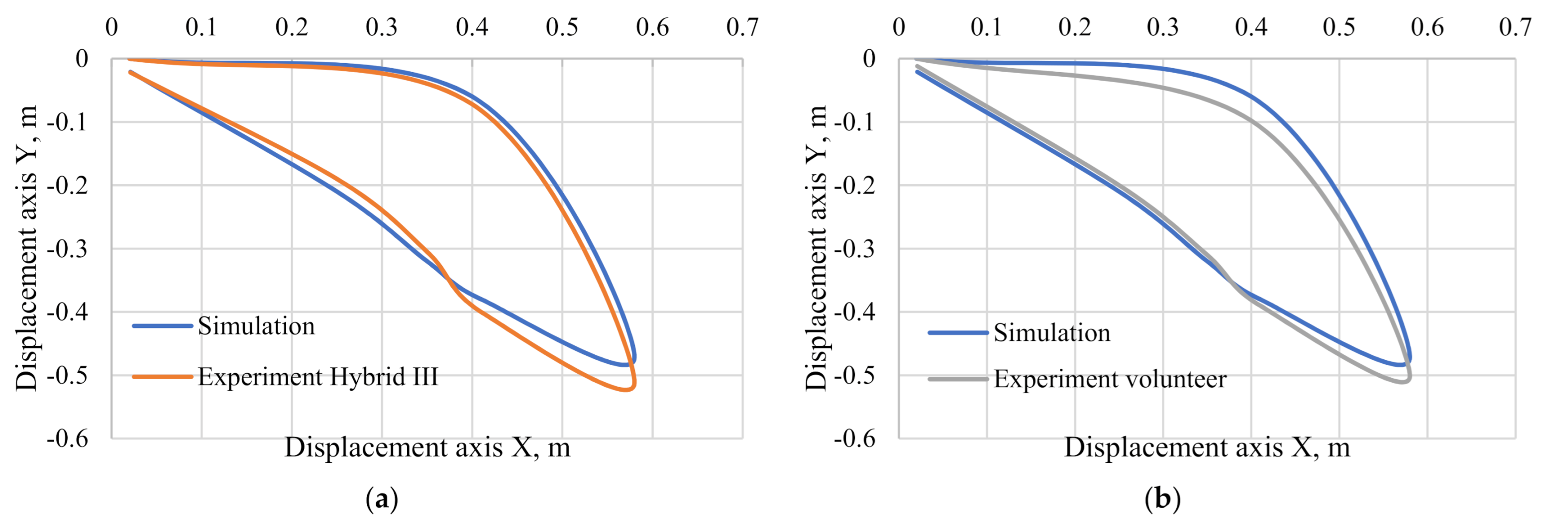
3. Results of Simulation Tests

The analysis of the film and the elaboration of the results were done with the aid of the TEMA program. This program allows us to analyze the movement of objects recorded with the camera. The program included a head movement trajectory for both the Hybrid III dummy and the volunteer. Figure 7 shows a comparison of the simulated dummy head displacement with the research experiments. It should be noted that in the case of comparing the results of computer simulation studies with the results of Hybrid III and volunteers, the compliance is at the level of 88%. The result in the first phase of the head movement caused by the sudden stopping of the seat is characterized by a perfect mapping of the simulation to real conditions, while in the case of the head returning to the vehicle seat, a difference of 12% is visible, which is caused by the difference in the stiffness of the seats in the computer simulation and the experiment.
Table 3 shows the percent accuracy of the dummy’s head displacement, in the first phase of the impact, when the dummy’s head tilts the most forward and in the second phase, when the dummy’s head returns to the vehicle seat and tilts its most rearward. It can be seen that for both the X-axis and the Y-axis in the first phase of the head movement, the difference between the simulation dummy and the hybrid III dummy is up to 5%. The simulation dummy is characterized by greater accuracy with the hybrid III dummy. It should be noted that the volunteer does not have anthropometric dimensions typical for the 50th percentile of the population, which may result in a lower accuracy of data replication in the comparison of the simulation of the dummy with the volunteer.
Figure 8 shows a comparison of the first phase of the movement of the computer simulation and the experiment with the Hybrid III dummy. The difference in the results is 5%.
Using TEMA software, the accelerations acting on the head of the Hybrid III dummy and the volunteers were determined. However, for the simulation dummy, the accelerations acting on the head were determined in the ADAMS program. The results of the dynamic analysis for the three types of studies showed a slight difference in the course of the accidental head acceleration. The resultant acceleration of the simulation dummy’s head was compared with the result of the Hybrid III dummy and the volunteer in Figure 9.

4. Conclusions

The anthropometric dummies and simulation dummies used are used for crash tests from a speed of 40 km/h. It should be noted that at this speed, the human body behaves differently than in a collision with a speed of 20 km/h. Low speed collisions occur especially in the case of rear collisions as a result of the vehicle speed and distance not being adjusted. In addition, rear collisions are becoming more frequent due to the development of the infrastructure of expressways and highways, where traffic flows in one direction. It should be noted that there is a need to build a test dummy at a low speed of impact, as the human body will behave differently in a collision at 20 km/h than in a collision at 50 km/h. Serious damage to the spine can occur even in a collision with a speed of 20 km/h. In addition, at this speed, the airbag will not be activated in a passenger vehicle, so a collision could seriously damage occupants’ health [61,62].
The current crash test dummies have been designed to best reflect the human body. In addition, the dummies were divided into rear, side, and front crash tests. Because they are constructed in such a way as to collect as much information as possible to help in the detection of injuries and the improvement of passenger vehicle safety. In the scientific literature, there are many scientific publications on the comparisons of anthropometric mannequins among themselves, thanks to which we know perfectly well which mannequin better replicates a given part of a human. For example, the BIORID II manikin reproduces a human spine better than the Hybrid III manikin. Therefore, it is recommended for rear crash tests. It should be emphasized that the current dummies are a specialized research unit equipped with thousands of sensors. The authors would like to point out that each of the dummies has its own purpose and there is no one universal dummy that could be used in any type of crash test at any speed which would perfectly replicate the human body.
The ADAMS program enables modification of the dummy’s construction and adopted model parameters. Comparing the computer simulation with the experiment at 20 km/h showed that the computer simulation data differed from the experimental data by 12%. Moreover, by modifying the stiffness and damping parameters as well as the mass of individual parts of the dummy’s body, it is possible to obtain crash test data taking into account individual percentiles of the human population.
The model made in the ADAMS program is a conceptual model on the basis of which the physical model will be made. The simulation model has knee and shoulder joints, which are patent applications [63,64,65]. These joints were first tested using the ADAMS program, and then, after successful attempts to reproduce the ranges of human body motion, they were made and incorporated into a physical model of dummy. The comparison of the simulation model with the actual experiment shows that such selected parameters of stiffness and damping in individual joints are able to reproduce individual movements of the human body.
Work on the physical structure of the simulation dummy involves the use of elements corresponding to the shape, mass, and dimensions of individual parts of the human body, as well as the use of special joints reflecting the range of motion of individual human joints [44].
The tests carried out to compare the constructed dummy with the experiments confirm the validity of the construction of the crash test dummy at low speed. In addition, it marks the beginning of work on an anthropometric dummy used in low speed crash tests for both front and rear collisions and with different impact angles.

Author Contributions

Conceptualization, D.F.; formal analysis, D.F. and M.J.; funding acquisition, D.F.; methodology, D.F. and M.J.; project administration, D.F. and M.J.; resources, D.F.; software, D.F. and M.J.; writing—original draft, D.F. and R.C.; Writing—review & editing, M.J. and J.M. All authors have read and agreed to the published version of the manuscript.

Funding

The research was financed by the National Centre for Research and Development, grant number POIR.04.01.04 00 0004/19 00.

Acknowledgments

The research was carried out as part of the Innovative system research project supporting the motor vehicle insurance risk assessment dedicated to UBI (Usage Based Insurance) No. POIR.04.01.04 00 0004/19 00 financed by the National Centre for Research and Development.

Conflicts of Interest

The authors declare no conflict of interest.

References

  1. Nie, B.; Sathyanarayan, D.; Ye, X.; Crandall, J.R.; Panzer, M.B. Active muscle response contributes to increased injury risk of lower extremity in occupant–knee airbag interaction. Traffic Inj. Prev. 2017, 19, 76–82. [Google Scholar] [CrossRef]
  2. Corazza, M.; Trincone, S.; Virgili, A. Effects of Airbag Deployment. Am. J. Clin. Dermatol. 2004, 5, 295–300. [Google Scholar] [CrossRef]
  3. THOR-50M Qualification Procedures Manual. Available online: https://www.nhtsa.gov/sites/nhtsa.dot.gov/files/thor-50m_qualification_august2016.pdf (accessed on 1 February 2021).
  4. Description and Performance of the Hybrid III Three-Year-Old, Six-Year-Old and Small Female Test Dummies in Restraint System and Out-Of-Position Air Bag Environments. Available online: https://www.nhtsa.gov/sites/nhtsa.dot.gov/files/1998esvpaper.pdf (accessed on 1 February 2021).
  5. Dębecki, R. Kiedy Działa Airbag? [When Does Airbag Work?]. Available online: https://www.auto-swiat.pl/porady/eksploatacja/kiedy-dziala-airbag/cfbvlwt (accessed on 1 February 2021).
  6. Kostek, R.; Aleksandrowicz, P. Simulation of car collision with an impact block. In Proceedings of the 11th International Congress of Automotive and Transport Engineering 2017, Pitesti, Romania, 8–10 November 2017; pp. 1–6. [Google Scholar] [CrossRef] [Green Version]
  7. Cunningham, K.; Brown, T.D.; Gradwell, E.; Nee, P.A. Airbag associated fatal head injury: Case report and review of the literature on airbag injuries. Emerg. Med. J. 2000, 17, 139–142. [Google Scholar] [CrossRef] [Green Version]
  8. Liu, Z.; Zhang, X.; Chen, H.; Shi, Y. Optimization of calibration parameters for hybrid III 5th female dummy neck calibration based on taguchi method. In Proceedings of the 2010 Third International Conference on Information and Computing, Wuxi, China, 6 June 2010; Volume 4, pp. 97–100. [Google Scholar] [CrossRef]
  9. Goo, A.; Laubscher, C.A.; Farris, R.J.; Sawicki, J.T. Design and Evaluation of a Pediatric Lower-Limb Exoskeleton Joint Actuator. Actuators 2020, 9, 138. [Google Scholar] [CrossRef]
  10. Lemmen, P.; Hynd, D.; Carroll, J.; Davidsson, J.; Bernard, B.; Song, E.; Steeger, B. Thoracic Injury Assessment for Improved Vehicle Safety. Procedia Soc. Behav. Sci. 2012, 48, 1649–1661. [Google Scholar] [CrossRef] [Green Version]
  11. Frej, D.; Zuska, A.; Cadge, K. Analysis of vertical vibrations affecting a child transported in a child seat during a vehicle passing over the release speed bump. Arch. Automot. Eng. 2019, 86, 111–125. [Google Scholar] [CrossRef]
  12. Amiri, S.; Naserkhaki, S.; Parnianpour, M. Modeling and validation of a detailed FE viscoelastic lumbar spine model for vehicle occupant dummies. Comput. Biol. Med. 2018, 99, 191–200. [Google Scholar] [CrossRef]
  13. Nycz, D. Influence of selected design parameters of the composite-foam cover rail on the course of the TB11 crash test of a road safety barrier forming a horizontal concave arc. Arch. Automot. Eng. Arch. Motoryz. 2017, 76. [Google Scholar] [CrossRef]
  14. Szada-Borzyszkowski, W.; Szada-Borzyszkowska, M. Wpływ prędkości pojazdów na wielkość uszkodzeń podczas zderzenia (Influence of vehicle speed on the magnitude of damage during a collision). Autobusy Tech. Eksploat. Syst. Transp. 2015, 16, 224–227. [Google Scholar]
  15. Brolin, K.; Stockman, I.; Andersson, M.; Bohman, K.; Gras, L.L.; Jakobsson, L. Safety of children in cars: A review of biomechanical aspects and human body models. Iatss Res. 2015, 38, 92–102. [Google Scholar] [CrossRef] [Green Version]
  16. Żuchowski, A. Seatbelt impact on a child during a frontal collision. Arch. Automot. Eng. Arch. Motoryz. 2017, 75. [Google Scholar] [CrossRef]
  17. Żuchowski, A. Analysis of the influence of the vehicle impact velocity on the loads of the dummies in the front and rear seats. Arch. Automot. Eng. Arch. Motoryz. 2018, 81, 159–176. [Google Scholar] [CrossRef]
  18. Available online: https://www.humaneticsatd.com (accessed on 1 January 2020).
  19. Final Publishable Report. Available online: https://ec.europa.eu/transport/road_safety/sites/roadsafety/files/pdf/projects_sources/fid_final_report.pdf (accessed on 1 January 2020).
  20. Stańczyk, T.L.; Zuska, A. Review of anthropodynamic dummies used to evaluate the effect of vibrations on sitting human (vehicle driver). Arch. Automot. Eng. Arch. Motoryz. 2014, 65, 65–74. [Google Scholar]
  21. Jaśkiewicz, M.; Jurecki, R.; Witaszek, K.; Więckowski, D. Overview and analysis of dummies used for crash tests. Sci. J. Marit. Univ. Szczec. 2013, 35, 22–31. [Google Scholar]
  22. Kent, R.; Bass, C.; Woods, W.; Salzar, R.; Lee, S.; Melvin, J. The role of muscle tensing on the force-deflection response of the thorax and a reassessment of frontal impact thoracic biofidelity corridors. J. Automob. Eng. Proc. Inst. Mech. Eng. 2006, 220, 853–868. [Google Scholar] [CrossRef]
  23. Jaśkiewicz, M.; Więckowski, D.; Witaszek, K. Przegląd i analiza manekinów stosowanych do testów zderzeniowych (Review and analysis of crash test dummies). Zesz. Nauk. Mech. Politech. Opol. 2013, 101, 47–48. [Google Scholar]
  24. Lemmen, P.; Been, B.; Hynd, D.; Carroll, J. Development of an advanced thorax/shoulder complex for the THOR dummy. In Proceedings of the Symposium on International Automotive Technology (SIAT), Pune, India, 9–12 January 2013; Volume 17, pp. 25–26. [Google Scholar] [CrossRef]
  25. Mohan, P.; Marzougui, D.; Kan, C. Development and Validation of Hybrid III Crash Test Dummy; SAE Technical Paper 2009-01-0473; SAE International; The George Washington University: Washington, DC, USA, 2009. [Google Scholar] [CrossRef]
  26. Zhang, W.; Kapoor, T.; Tot, M.; Altenhof, W. A Comparison of the Kinematics of a Child Finite Element Model and the HYBRID III 3-Year-Old Dummies in Frontal Crashes; SAE Technical Paper 2007-01-0977; SAE International: Warrendale PA, USA, 2007. [Google Scholar] [CrossRef]
  27. Wang, W.; Zhang, D.; Ji, J.; Tian, H.; Zhao, H. Seat belt protection of train driver during secondary impact. In Proceedings of the 2016 IEEE International Conference on Intelligent Transportation Engineering (ICITE), Singapore, 20–22 August 2016; pp. 85–88. [Google Scholar] [CrossRef]
  28. Jaśkiewicz, M.; Więckowski, D.; Poliak, M.; Frej, D. Shoulder joint design of the anthropometric dummy used for crash tests. In Proceedings of the 2020 XII International Science-Technical Conference Automotive Safety, Kielce, Poland, 21–23 October 2020; pp. 1–5. [Google Scholar] [CrossRef]
  29. Nordhoff, L.; Freeman, M.; Siegmund, G. Human Volunteer and Anthropomorphic Dummy Tests of General Motors Driver Air Cushion System, SAE Paper No. 740578, Society of Automotive Engineers, Warrendale, PA, 1974. In Human Subject Crash Testing: Innovations and Advances; SAE International: Warrendale, PA, USA, 2007; pp. 307–321. [Google Scholar]
  30. Biofidelity Impact Response Requirements for an Advanced Mid-Sized Male Crash Test Dummy. Available online: https://hal.archives-ouvertes.fr/hal-01490941/document (accessed on 1 January 2020).
  31. Forman, J.; Poplin, G.S.; Shaw, C.G.; McMurry, T.L.; Schmidt, K.; Ash, J.; Sunnevang, C. Automobile injury trends in the contemporary fleet: Belted occupants in frontal collisions. Traffic Inj. Prev. 2019, 20, 607–612. [Google Scholar] [CrossRef]
  32. Han, Y.; Tang, H.; Tian, F.; Huang, H.; Mizuno, K. Analysis of the equation of motion on the chest of hybrid III 3YO dummy in dynamic loads. In Proceedings of the 2018 International Conference on Robots and Intelligent System (ICRIS), Changsha, China, 26–27 May 2018; pp. 529–533. [Google Scholar] [CrossRef]
  33. Ludwinek, K.; Jurecki, R.; Jaskiewicz, M.; Szumska, E.; Sulowicz, M. A test stand for the experimental analysis of physical quantities during crash test at low speeds. In Proceedings of the 2018 XI International Science-Technical Conference Automotive Safety, Casta, Slovakia, 18–20 April 2018; pp. 1–7. [Google Scholar] [CrossRef]
  34. Manary, M.A.; Klinich, K.D.; Orton, N.R.; Reed, M.R.; Rupp, J.D. Comparing the CRABI-12 and CRABI-18 for Infant Child Restraint System Evaluation; (Report No. DOT HS 812 156); National Highway Traffic Safety Administration: Washington, DC, USA, 2015. Available online: https://www.nhtsa.gov/sites/nhtsa.dot.gov/files/documents/11316-crabi_12and18_060215_v4_tag.pdf (accessed on 1 February 2021).
  35. Bertocci, G.E.; Szobota, S.; Hobson, D.A.; Digges, K. Computer simulation and sled test validation of a powerbase wheelchair and occupant subjected to frontal crash conditions. IEEE Trans. Rehabil. Eng. 1999, 7, 234–244. [Google Scholar] [CrossRef]
  36. Thuong, L.N.P. Vehicle frontal impact to pole barrier simulation using computer finite element model. In Proceedings of the 2018 4th International Conference on Green Technology and Sustainable Development (GTSD), Ho Chi Minh City, Vietnam, 23–24 November 2018; pp. 273–277. [Google Scholar] [CrossRef]
  37. Sun, Y.; Sun, X.; Rong, J.; Tai, Y. Development of energy absorbing refuge island using crash simulation. In Proceedings of the 2011 International Conference on Transportation, Mechanical, and Electrical Engineering (TMEE), Changchun, China, 16–18 December 2011; pp. 1012–1015. [Google Scholar] [CrossRef]
  38. Zhang, Y.; Song, J.; Qian, Y.; Gao, Q. Simulation and optimization of vehicle side airbag. In Proceedings of the 2018 International Computers, Signals and Systems Conference (ICOMSSC), Dalian, China, 19–21 December 2018; pp. 320–323. [Google Scholar] [CrossRef]
  39. Shameem, S.; Prasad, G.R.K.; Ch, V.T.; Kumar, K.B.; Yaswanth, M.; Ch, M. Design simulation and analysis of crash sensor for air bag system. In Proceedings of the 2018 3rd International Conference on Inventive Computation Technologies (ICICT), Coimbatore, India, 15–16 November 2018; pp. 718–723. [Google Scholar] [CrossRef]
  40. Sharma, A.; Sharma, S.; Chhabra, M. Recent Developments in Airbags for Passenger Safety in Automobile Engineering. Int. J. Res. Advent Technol. 2017, 5, 2321–9637. [Google Scholar]
  41. He, P.; Jiang, X.; Yang, J. A Study on rear seat occupant injuries in side impact. In Proceedings of the 2012 Third International Conference on Digital Manufacturing and Automation, GuiLin, China, 31 July–2 August 2012; pp. 144–147. [Google Scholar] [CrossRef]
  42. Zhang, Y.; Ju, C.; Yue, G.; Chen, X.; Sun, H. Simulation analysis of the rear seat female in front impact. In Proceedings of the 2012 Third International Conference on Digital Manufacturing and Automation, GuiLin, China, 31 July–2 August 2012; pp. 767–770. [Google Scholar] [CrossRef]
  43. Ruhai, G.; Manjiang, H.; Dong, X. Simulation study of bus occupant restraint system in emergency brake. In Proceedings of the 2010 International Conference on Optoelectronics and Image Processing, Haikou, China, 11–12 November 2010; pp. 392–395. [Google Scholar] [CrossRef]
  44. Jaśkiewicz, M.; Frej, D.; Tarnapowicz, D.; Poliak, M. Upper limb design of an anthropometric crash test dummy for low impact rates. Polymers 2020, 12, 2641. [Google Scholar]
  45. Sonawane, C.R.; Shelar, A.L. Strength Enhancement of Car Front Bumper for Slow Speed Impact by FEA Method as per IIHS Regulation. J. Inst. Eng. India Ser. C 2018, 99, 599–606. Available online: https://doi.org/10.1007/s40032-017-0365-y (accessed on 2 March 2021). [CrossRef] [Green Version]
  46. Jakobsson, L.; Norin, H.; Bunketorp, O. In-depth study of whiplash associated disorders in frontal Impacts: Influencing factors and consequences. In Proceedings of the International IRCOBI Conference on the Biomechanics of Impact, Munich, Germany, 18–20 September 2002; pp. 211–222. [Google Scholar]
  47. Croft, A.C.; Eldridge, T.R. Human subject rear passenger symptom response to frontal car-to-car low-speed crash tests. J. Chiropr. Med. 2011, 10, 141–146. [Google Scholar] [CrossRef] [Green Version]
  48. Krafft, M.; Kullgren, A.; Ydenius, A.; Boström, O.; Håland, Y.; Tingvall, C. Rear impact neck protection by reducing occupant forward acceleration—A study of cars on Swedish roads equipped with crash recorders and a new anti-whiplash device. In Proceedings of the International IRCOBI Conference, Graz, Austria, 22–24 September 2004; pp. 221–231. [Google Scholar]
  49. Jaśkiewicz, M.; Frej, D.; Šarkan, B. Construction of the knee joint of the dummy designed for crash tests. Trans. Res. Procedia 2020, 44, 121–128. [Google Scholar] [CrossRef]
  50. Nordhoff, L.; Freeman, M.; Siegmund, G. Kinetic and kinematic responses of the RID2a, hybrid III, and human volunteers in low-speed rear-end collisions. Stapp Car Crash J. 2001, 45, 239–256, (in Human Subject Crash Testing: Innovations and Advances, SAE 2007, 865–882). [Google Scholar]
  51. Nordhoff, L.; Freeman, M.; Siegmund, G. TRL Rear Impact Volunteer Testing: Methods and Measurements. In Human Subject Crash Testing: Innovations and Advances, Proceedings of the 1st APSN Workshop on Biomechanical Experiments, Advanced Passive Safety Network, Graz, Austria, 21 September 2004; SAE International: Warrendale, PA, USA, 2007; pp. 611–627. [Google Scholar]
  52. Nordhoff, L.; Freeman, M.; Siegmund, G. Human Volunteer Head-T1 Response for Oblique Impact Conditions. In Human Subject Crash Testing: Innovations and Advances, Proceedings of the International IRCOBI Conference on the Biomechanics of Impact, Graz, Austria, 22–24 September 2004; pp. 53–68; SAE International: Warrendale, PA, USA, 2007; pp. 269–284. [Google Scholar]
  53. Nordhoff, L.; Freeman, M.; Siegmund, G. Relationship between localized spine deformation and cervical vertebral motions for low speed rear impacts using human volunteers. In Human Subject Crash Testing: Innovations and Advances, Proceedings of the International IRCOBI Conference on the Biomechanics of Impact, Stiges, Spain, 23–24 September 1999; pp. 149–164; SAE International: Warrendale, PA, USA, 2007; pp. 773–788. [Google Scholar]
  54. Yamazaki, K.; Ono, K.; Ishii, M. Biofidelity of rear impact dummies in low speed rear-end impact: Comparison of rigid seat and mass production car seat in human volunteers. International Phantom data sheet. In Proceedings of the 2008 International Ircobi Conference on the Biomechanics of Injury, Bern, Switzerland, 17–19 September 2008; Available online: http://www.komiweb.co.kr/data/v310.pdf (accessed on 22 February 2020).
  55. Castro, W.H.; Meyer, S.J.; Becke, M.E.; Nentwig, C.G.; Hein, M.F.; Ercan, B.I.; Thomann, S.; Wessels, U.; Du Chesne, A.E. No stress—No whiplash? Prevalence of “whiplash” symptoms following exposure to a placebo rear-end collision. Int. J. Leg. Med. 2001, 114, 316–322. [Google Scholar] [CrossRef] [PubMed]
  56. Nordhoff, L.S., Jr.; Freeman, M.D.; Siegmund, G.P. Human Subject Crash Testing: Innovations and Advances (PT-134); SAE International: Warrendale, PA, USA, 2007; ISBN 9780768019315. [Google Scholar]
  57. Hynd, D.; Willis, C.; Roberts, A. TRL rear impact volunteer testing: Method and measurements. In Proceedings of the D16-WG 5.2 Workshop on Biomechanical Experiments, Berks, UK, 21 September 2004; pp. 18–28. [Google Scholar]
  58. Lopez-Valdes, F.J.; Kent, R.; Arbogast, K.; Higuchi, K. Analysis of spinal motion during frontal impacts. Comparison between PMHS and ATD. Ann. Adv. Automot. Med. 2010, 54, 61–78. [Google Scholar] [PubMed]
  59. Noureddine, A.; Eskandarian, A.; Kennerly, D. Computer modeling and validation of a Hybrid III dummy for crashworthiness simulation. Math. Comput. Model. 2002, 35, 885–893. [Google Scholar] [CrossRef]
  60. Bailey, A.; Chirstopher, J.; Henderson, K.; Brozoski, F.; Salzar, R.S. Comparison of hybrid-III and PMHS response to simulated underbody blast loading conditions. In Proceedings of the 13th International Research Council on the Biomechanics of Injury Conference (IRCOBI), Gothenburg, Sweden, 11–13 September 2013; pp. 58–171. [Google Scholar]
  61. Stand for Simulation Testing of Dynamic Stresses, Especially in the Elements Securing the Driver. Available online: https://patents.google.com/patent/PL430055A1/pl?oq=430055+ (accessed on 1 January 2020).
  62. Zellmer, H.; Muser, M.; Stamm, M.; Walz, F.; Hell, W.; Langweider, K.; Philippens, M. Performance comparison of rear impact dummies: Hybrid III (TRID), BioRID and RID 2. In Proceedings of the International IRCOBI Conference on the Biomechanics of Impact, Munich, Germany, 18–20 September 2002. [Google Scholar]
  63. Cappon, H.J.; Philippens, M.; van Ratingen, M.R.; Wismans, J.S.H.M. Evaluation of dummy behaviour during low severity rear impact. In Proceedings of the IRCOBI Conference on the Biomechanics of Impact, Montpeller, France, 20–22 September 2000; pp. 53–66. [Google Scholar]
  64. Frej, D.; Ja’skiewicz, M. Przegub Kolanowy Manekina Antropometrycznego do Testów Zderzeniowych [Knee-Joint of the Anthropometric Crash Test Dummy]. PL. Patent P.431522, 21 October 2019. [Google Scholar]
  65. Frej, D.; Ja´skiewicz, M. Przegub Barkowy Manekina Antropometrycznego do Testów Zderzeniowych [Shoulder Joint of the Anthropometric Crash Test Dummy Application]. PL. Patent P.433041, 27 February 2020. [Google Scholar]
Figure 1. Anthropometric dummy for the THOR crash test [18]: (a) THOR-50th Dummy; (b) THOR-FT dummy CAD (Computer aided design)-model.
Energies 14 01476 g001
Figure 2. Children’s dummies [18]: (a) Seria Q FE, (b) Hybrid III Children Series FE, (c) CRABI-12MO FE.
Energies 14 01476 g002
Figure 3. Anthropometric dummy for crash tests made in ADAMS program.
Energies 14 01476 g003
Figure 4. Test stand located at the Automotive Industry Institute in Warsaw.
Energies 14 01476 g004
Figure 5. Displacement of the dummy at selected moments of time.
Energies 14 01476 g005
Figure 6. Test stand for crash tests at low speed.
Energies 14 01476 g006
Figure 7. Displacement of the dummy head (a) relative to the X axis, (b) relative to the Y axis.
Energies 14 01476 g007
Figure 8. Head movement trajectory; (a) head displacement comparison for the simulation dummy and the Hybrid III dummy, (b) head displacement comparison for simulation dummy and volunteer.
Energies 14 01476 g008
Figure 9. The resultant head acceleration.
Energies 14 01476 g009
Table 1. The masses of individual body parts of the simulation dummy.
The Name of the BlockMass (kg)
forearm3.60
arm0.50
hand4.60
food9.4
shank0.60
thigh13.80
neck0.95
head3.70
hips20.40
chest9.80
stomach10.00
(Σ)78.7
Table 2. Volunteer anthropometric dimensions.
ParametersValuesAllocation to the Population Percentile
Mass (kg)90C95
Height (cm)181C95
Head circumference (cm)59C95
Torso length (cm)60C95
Chest circumference (cm)108C95
Arm circumference (cm)37C50
Arm length (cm)33C50
Forearm circumference (cm)31C50
Wrist circumference (cm)20C50
Wrist width (cm)10C50
Hand width (cm)25C95
Thigh circumference (cm)57C50
Circumference of the lower leg (cm)40C50
Ankle circumference (cm)26C50
Foot length (cm)24C50
Table 3. Comparison of the accuracy of the dummy head displacement.
ComparisonThe First Phase of the Head MovementThe Second Phase of Head Movement
Relative to the X AxisRelative to the Y AxisRelative to the X AxisRelative to the Y Axis
Simulation dummy—Hybrid III dummy95%98%88%89%
Simulation dummy—Volunteer94%90%94.5%82%
Publisher’s Note: MDPI stays neutral with regard to jurisdictional claims in published maps and institutional affiliations.

