Article

In-Service Thermal and Luminous Performance Monitoring of a Refurbished Building with Solar Control Films on the Glazing System

by
Henriqueta Teixeira
,
Maria da Glória Gomes
*,
António Moret Rodrigues
and
Júlia Pereira
Civil Engineering Research and Innovation for Sustainability (CERIS), Department of Civil Engineering, Architecture and Georresources (DECivil), Instituto Superior Técnico, Universidade de Lisboa, Av. Rovisco Pais, 1049-001 Lisbon, Portugal
*
Author to whom correspondence should be addressed.
Energies 2021, 14(5), 1388; https://doi.org/10.3390/en14051388
Submission received: 13 February 2021 / Revised: 26 February 2021 / Accepted: 27 February 2021 / Published: 3 March 2021
(This article belongs to the Special Issue Building Thermal Envelope - New Trends and Applications)

Abstract

:
The global increase in energy needs and environmental awareness for a more efficient energy use have boosted building rehabilitation to decrease energy consumption. The installation of solar control films (SCFs) in buildings with large glazing façades makes it possible to reduce excessive solar gains through the glazing. The main purpose of the work is to assess, with field experimental data, the thermal and luminous performances of double-glazing units with SCFs installed in office rooms, in Lisbon. An experimental campaign was carried out simultaneously in three adjacent offices: one with a highly reflective SCF (external installation), one with a reflective SCF (internal installation) and one without an SCF. The exterior SCF showed the best thermal performance with reductions in the peak indoor air temperature of up to 6.9 and 2.3 °C during the representative days of the heating and cooling periods, respectively, increasing thermal comfort mainly during the cooling period. The interior SCF had a poorer thermal performance since it contributed to solar radiation absorption that is then emitted as heat into the indoor environment, increasing the greenhouse effect of the office. The presence of SCFs reduced the indoor illuminance levels, having a positive impact on thermal comfort and glare reduction in the cooling period.

1. Introduction

Glazing systems, as transparent elements of a building’s envelope, can have a positive or negative impact on the thermal and luminous qualities of buildings depending on the design and desired indoor comfort conditions. Glazing systems make it possible to benefit from solar heat gains and daylight, other than providing occupants a view of the outdoor environment. However, they can lead to excessive heat gains and visual discomfort (glare and asymmetrical daylight distribution) for the occupants [1,2,3,4]. Recent buildings, namely, commercial ones, are built with high window to wall ratios, having in mind potential energy savings in artificial lighting, apart from the esthetic design [5,6,7,8]. This architectural trend can lead to indoor thermal and luminous discomfort conditions that are more severe in countries with a very contrasting difference between the heating and cooling seasons, such as Portugal that has a Mediterranean climate [9,10,11].
The application of solar control films (SCFs) into existing or new glazing systems modifies the optical and thermal properties of the glass and is an alternative to other solar control solutions such as overhangs and blinds that may require a reconstruction of the fenestration system [12,13,14,15]. While not requiring façade alteration, SCFs can act as a refurbishment solution and contribute to the improvement of the luminous, thermal and energy performances of buildings.
The relatively scarce studies that investigate the impact of SCFs on the performance of buildings through experimental [16,17,18,19] or numerical [20,21,22,23,24,25] approaches, or both [26,27,28,29,30], generally conclude that the installation of SCFs can promote better thermal and visual performances and result in energy savings.
Noh Pat et al. [20] and Xáman et al. [21,22] concluded that the energy gains through a double-glazing unit with an SCF were reduced by 10% in cold climates, and between 55–62% in warm climates. Yin et al. [23] obtained a reduction in the solar heat gain coefficient of the glazing system of a large glazed commercial building up to 44% in the presence of SCFs applied on the external glass surface. According to Chaiyapinunt et al. [24], thermal comfort increases in the presence of SCFs when analyzing the effect of solar radiation on the indoor temperature. Amirkhani et al. [25] concluded that low-emissivity SCFs have a better performance comparing with reflective SCFs.
When analyzing the performance of glazing systems with SCFs in office rooms, significant reductions in the solar radiation income (up to 60%), the indoor illuminance (up to 65%), the cooling energy needs (up to 29%) and consumption (up to 13.1%) were obtained in the presence of films by previous studies [16,17,18,26,27,28]. Considering previous studies of the performance of single- [29] and double-glazing [30] systems with SCFs conducted in the city of Lisbon, Portugal, a better performance was obtained for SCFs installed on the external glass surface, and films with low solar transmittance made it possible to significantly reduce the cooling energy use (up to 86%). Comfortable levels of temperature and glare were obtained during up to 41% and 43% of working hours in a year [29,30].
Most of the reported studies [16,17,20,21,22,24,26,27] tend to assess the luminous and thermal performances of windows with SCFs and give a special focus to the energy performance, while the evaluation of the effect of SCFs on indoor comfort [24,25,28,29,30] is still very scarce. Since people spend, on average, 90% of the time indoors, in Europe [31], the indoor comfort assessment becomes significant and that is why it was taken into account in the present experimental study. Moreover, the experimental studies conducted in real occupancy in the Mediterranean climate are still very limited [29,30].
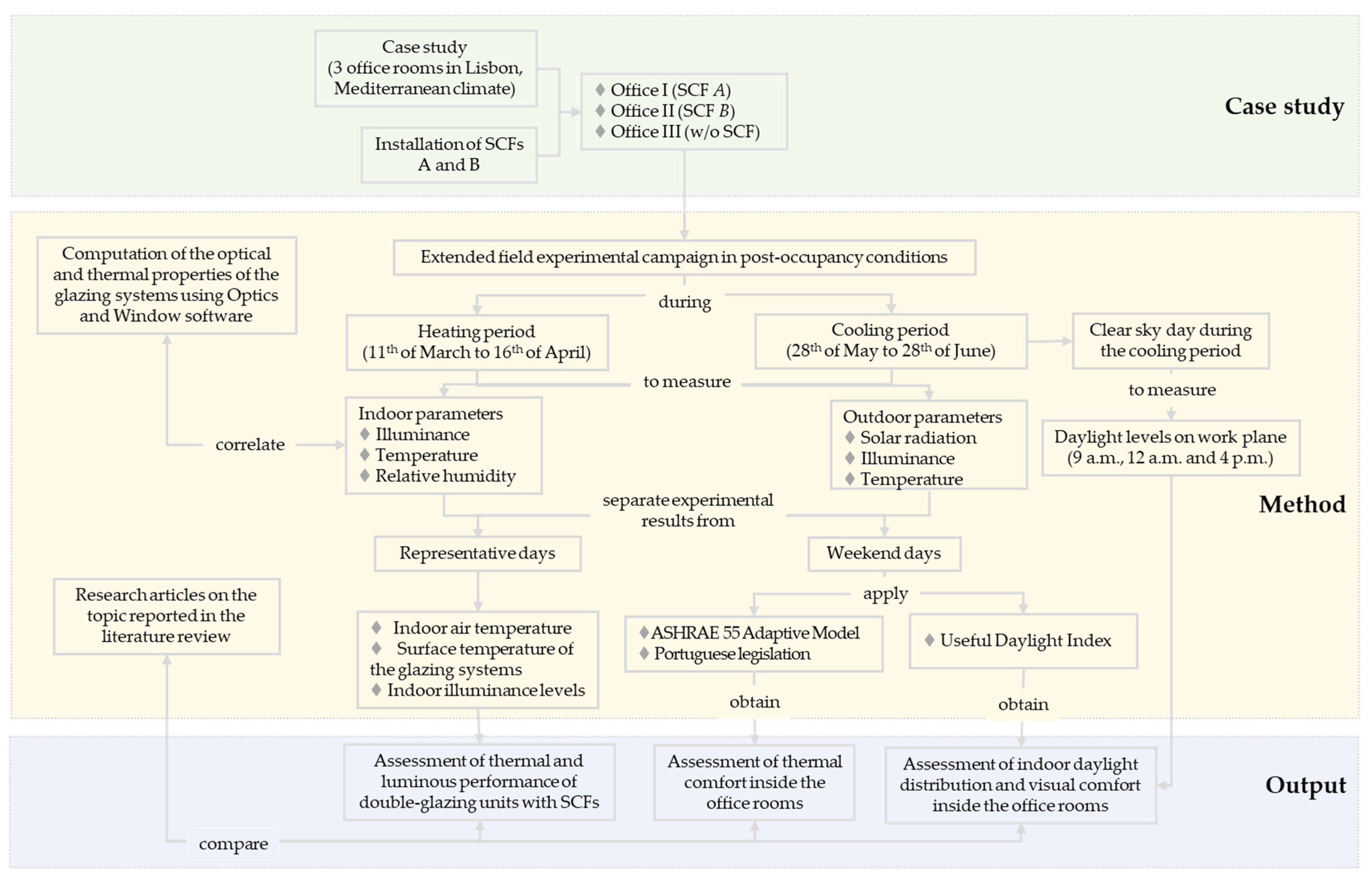
The present study aims to pursue the research on this subject and help to fill some gaps that still exist in experimental research on the evaluation of the thermal and luminous performances of window films in the Mediterranean climate. An experimental integral evaluation approach is proposed involving thermal and luminous performances and visual and thermal indoor comfort conditions assessment in office rooms with glazing systems with and without SCFs, in the city of Lisbon (coordinates: 38°7′ N, −9°1′ W). The research proposed in the present study is illustrated in Figure 1.

2. Methodology

The present study used three office rooms for the case study, where the thermal and luminous performances of glazing systems with and without solar control films (SCFs) were experimentally evaluated during heating and cooling periods. The luminous and thermal performances of double-glazing units were analyzed for specific representative days of both periods. The percentage of working hours within thermal and visual comfort was analyzed for both periods and compared between office rooms. Moreover, measurements of the indoor daylight levels on the work plane were made in the office rooms during a clear sky day. The methodology followed in the present study is illustrated in Figure 2.

2.1. Case Study

Three adjacent individual office rooms (Figure 3a) were selected as the case study for the experimental evaluation of the luminous and thermal performances of double-glazing units with and without SCFs installed on the internal or external glazing surface. The offices are located on the top floor of a building (Figure 3a) at Instituto Superior Técnico (IST), Alameda campus, Lisbon. The city of Lisbon has a hot-summer Mediterranean climate, characterized by high solar radiation levels and wind, cool wet winters and hot, dry summers, with precipitation usually between October and April [9,32].
The three adjacent office rooms were selected as the case study of the present work because of their similar location, configuration and occupancy conditions that make it possible to highlight performance differences when comparing results of the glazing systems between office rooms. The dimensions (length and width) of the office rooms are shown in Figure 3b. The office rooms have the same height (2.97 m), glazing area (10.38 m2) and solar orientation of the exterior façade (southeast) and a similar configuration and floor area (19 m2). The envelope has the same opaque and transparent elements in each office room. The original glazing system of the office rooms is composed of a double-glazing unit of clear float glass filled with air (6 + 12 + 4 mm) and an aluminum frame (without a thermal break). In the year of 2006, a reflective solar control film (named in the present study as SCF B) was applied on the original glazing system (internal glass surface) to decrease the thermal and visual discomfort in the indoor environment caused by excessive solar heat gains and high visible light transmittance through the original glazing system. The offices have internal Venetian blinds (manually controlled) with light-colored aluminum horizontal slats to supply shade to the glazing. The protruding south façade of the building (dotted light blue line in Figure 3a) causes a shading effect on the exterior façade (oriented southeast), which is usually observed around 12 a.m. (summer) or 2 p.m. (winter), starting to shade office I and later the other offices (taking approximately 45 min to completely shade all three offices). Figure 3c shows the outdoor view of the office rooms of the case study, identifying the glazing systems on the exterior façade of the building. The offices have the same artificial lighting system and electric equipment. During working hours, occupants can control the indoor air temperature using a variable refrigerant volume (VRV) unit with a setpoint of 22 ± 2 °C (pre-established for the building).
A field experimental campaign was carried out simultaneously in the three offices [33]. To help in evaluating the impact of SCFs on the thermal and luminous performances of the case study double-glazing system, a highly reflective solar control film (named in the present study as SCF A) was installed on the glazing system of office I (external glass surface), the existing SCF (named in the present study as SCF B) previously applied on the original glazing system (internal glass surface) was maintained in office II and this same solar control film (internally applied on the original glazing) was removed in office III. The installed SCFs have a sputtered metal layer, silver appearance and thickness of 60 (SCF A) and 45 µm (SCF B). Figure 4 shows the removal of the existing solar control film (SCF B), which was previously installed on the internal glass surface of the original glazing, in office I (the removal was also conducted in office III), and also the cleaning works and installation of the new SCF A on the glazing (external glass surface) of office I.
Figure 5a–c shows the configuration of the glazing systems during the experimental campaign. For comparison purposes, office III that does not have a solar control film installed on its glazing system is taken as the reference office. Figure 5d–f shows the transmittance and the front and back reflectance of the glazing values in the ultraviolet (UV), visible and infrared (IR) radiation wavelengths of the solar spectrum for the three glazing systems, computed using Optics software. The reduction in solar radiation transmittance can be observed in the presence of the SCFs comparing with the reference glazing (Figure 5f) full-spectrum results. Comparing with the original glazing (without an SCF), the solar radiation reflectance increases in the presence of the SCFs, mainly on the surface they are installed on, according to Figure 5d,e.
Table 1 presents the main optical and thermal properties of the studied glazing systems, computed through Optics and Window [34] software. By comparing the computed properties, it is possible to notice that the thermal transmittance is identical for the three glazing systems. The glazing system with SCF A, corresponding to the glazing with the lowest g value, is expected to have the highest thermal performance. The reference glazing system has the highest visible transmittance and the lowest visible reflectance. The SCFs made it possible to increase the visible reflectance of the glazing systems, with the most reflective glazing resulting from the installation of SCF A. By analyzing the computed values of the solar transmittance, a significant decrease in the heat solar gains that are transmitted through the glazing is expected in the presence of the glazing systems with SCFs, particularly for the glazing with SCF A. The installation of the films resulted in an increase in the solar reflectance of the glass surface the films are installed on. The increase in the solar back reflectance of the glazing with SCF B (internal glass surface) may result in an increase in the indoor air temperature of the office, since a portion of the radiation is reflected to the indoor environment. The transmittance of ultraviolet radiation was significantly reduced in the presence of the SCFs, possibly resulting in health and material conservation benefits. The presence of SCFs altered the absorptance of the glass panes, resulting in an increase in the solar absorptance of the external and internal glass panes for the glazing systems with solar control films A and B, respectively, with external and internal application. The selected SCFs slightly reduce the thermal emissivity of the glass surface where they are applied on. The glazing system taken as reference (without an SCF) and the glazing with SCF A installed have the same selectivity ratio (SS).

2.2. Experimental Setup

The experimental campaign [33] was conducted during two distinct periods: from 11 March to 16 April (named in the present work as heating period) and from 28 May to 28 June (named in the present work as cooling period). The parameters presented in Table 2 were measured simultaneously in the three offices: outdoor and indoor air temperature; internal and external surface temperatures of the glazing systems; surface temperature of the aluminum slats of the Venetian blinds; outdoor global (horizontal and vertical planes) and diffuse (horizontal plane) solar radiation; outdoor illuminance (horizontal plane); indoor illuminance (vertical plane); indoor air temperature, illuminance (horizontal plane) and relative humidity at the desk of the office rooms. The measuring equipment used to record the parameters (Table 2) was coupled to data acquisition systems that registered the experimental data in ten-minute averages resulting from one-minute records: DataTaker DT85 (office I); Delta-T DL2e (office II); Campbell CR10X (office III).
The location of the experimental equipment in the reference office (office III) and on the flat roof is shown in Figure 6.
Figure 7 shows photos of the experimental equipment that were captured during the experimental campaign. The Venetian blinds of the offices were kept at the same position during the experimental data measuring periods (Figure 7f).

3. Results

Experimental measurements during working hours (between 9 a.m. and 6 p.m.) of days when the VRV unit was turned on (weekdays) and off (weekends) were taken from the data collected in order to assess the hygrothermal and visual performances of the offices. Measurements were taken during weekdays to make it possible to assess the indoor environment of the offices in actual occupancy conditions. Experimental measurements were also taken during weekends, in a free-float temperature regime, making it easier to denote and differentiate the impacts of solar control films on the indoor environment.
Figure 8 shows the measured parameters of the hygrothermal performance of the offices, such as mean air (Ti), shading slats surface (Tss), internal (Tsi) and external (Tse) surface temperatures of the glazing systems and indoor relative humidity (RHin). Relative humidity measurements were not taken during the cooling period because during this period, the indoor air humidity is usually within the range of 40–70%, having a modest impact on the thermal sensation inside the office rooms which have a sedentary occupation and a moderate thermal environment [35]. The Ti and Tss temperatures are smaller in the presence of SCFs. The temperatures and relative humidity ranges measured inside the offices are smaller during the weekend because the internal gains are lower since the offices are not occupied.
The experimental results of the visible performance of the office rooms are presented in Table 3. The reference office has the highest average indoor illuminance levels and, consequently, the highest probability of indoor visual discomfort conditions due to possible glare occurrences. The presence of SCFs significantly reduced the indoor illuminance levels of both offices I and II when comparing with the reference office without an SCF. The highly reflective SCF A made it possible to achieve reductions of up to 94.3% in indoor illuminance levels.
A more detailed analysis of the experimental results is made in the next subchapters for representative days of the two measuring periods. The following representative days were selected for the heating period: the day with the lowest daily average outdoor air temperature (Dcoldest, 31 March); a day without the VRV unit operating (Dw/oC-H, 3 April); the day with the lowest daily average solar radiation on the vertical plane, during the sun hours period (Drad, 14 April). The following representative days were selected for the cooling period: the day with the highest daily average outdoor air temperature (Dhottest, 8 June); a day without the VRV unit operating (Dw/oC-C, 12 June); the day with the highest daily average solar radiation on the vertical plane, during the sun hours period (DRAD, 26 June). The days with the VRV unit turned off (Dw/oC-H and Dw/oC-C) were considered to minimize the impact of different occupants’ behavior in the results. The average and maximum outdoor air temperature and global solar radiation on the vertical plane for the selected representative days are presented in Table 4.

3.1. Heating Period

The data of the representative days of the heating period (Dcoldest, Dw/oC-H and Drad) are analyzed in the present subchapter, by evaluating the thermal and luminous performances of the glazing systems.

3.1.1. Temperature of the Indoor Air and of the Surface of the Glazing Systems

The outdoor ( T o u t ) and indoor ( T i ) air temperatures, internal ( T s i ) and external ( T s e ) glazing system surface temperatures and Venetian blinds slats ( T s s ) surface temperature along with the incident solar radiation on the vertical plane during the representative days are shown in Figure 9. Even though Dcoldest has the lowest minimum outdoor air temperature values, it shows the highest indoor temperature values measured during working hours due to the high outdoor solar radiation levels. The recorded temperatures for Drad were similar between offices due to the low outdoor levels of solar radiation and outdoor air temperature values being practically constant when comparing with the other two representative days.
The offices with an SCF presented an identical thermal performance for Dcoldest when analyzing the measured values of the indoor air temperature (Figure 9a). The highest values were measured in the presence of the reference glazing system (without an SCF) during most of the day. The maximum T i values of 23.3, 25.5 and 30.2 °C were obtained for offices I, II and III, respectively, showing the influence of SCFs on the reduction in the peak indoor air temperature. The maximum values and the temperature increase/decrease moments were not recorded at the same hour for all the offices because the VRV unit operating schedule is manually controlled by the occupants. An abrupt change in the indoor air temperature to values close to the VRV unit setpoint (22 ± 2 °C) indicates that the climatization was turned on. The influence of the glazing systems on the T i is better analyzed in Dw/oC-H, without climatization (Figure 9a), having the highest values recorded throughout the day for office III, followed by office II and, in last, office I. The presence of the SCFs decreased the solar transmittance and the heat gain coefficient of the glazing systems (Table 1), contributing to lower values of the indoor air temperature comparing with the results obtained for office III (without an SCF). The indoor temperature in office III (without an SCF) is rapidly influenced by the increase/decrease in the outdoor solar radiation, contrary to what is observed in the offices with SCFs that reflect most of the solar radiation. The measured indoor air temperature values were lower during Drad (Figure 9a) due to the low outdoor solar radiation (diffuse solar radiation—overcast day) and air temperature values. During this day, the measured indoor air temperature values were similar between offices, suggesting that SCFs are more efficient in reflecting direct solar radiation than diffuse radiation.
The aluminum shading slats surface temperature (Figure 9b) is higher than the indoor air temperature during the sun hours periods because aluminum has a very high thermal conductivity and the slats are located close to the glazing systems, receiving high levels of solar radiation that are absorbed by the slats and consequently increase the slats’ surface temperature. The values of T s s for office I (with SCF A externally applied) are the lowest ones because of its highly reflective glazing that drastically reduces the transmittance of the solar radiation and heat gains through the window. The reference glazing system, which has the highest solar transmittance, shows the highest temperature values of the slats’ surface. However, the temperature of the slats’ surface recorded during Dw/oC-H and Drad is very similar between offices II (SCF B) and III (without an SCF) because of the low outdoor solar radiation levels.
The measured values of the internal surface temperature of the glazing system (Figure 9c) are higher for office II that has SCF B installed on the internal glazing surface because the film increased the solar absorptance of the internal glass pane (Table 1). The glazing system of office I (SCF A) has the lowest values of T s i , since the SCF reflects a large part of the solar radiation and consequently contributes to the lower indoor temperature values, as stated before.
The measured values of the external surface temperature of the glazing systems (Figure 9d) are the closest ones to the outdoor air temperature values, as expected. The T s e values of the glazing systems with SCFs are slightly higher than the ones of the reference glazing, during the sun hours period, since the application of SCF A on the external glass surface (office I) increased the absorptance of the external pane (Table 1), increasing its surface temperature, and SCF B installed on the internal glass surface (office II) reflects part of the solar radiation towards the external glass surface of the glazing (Table 1), increasing its surface temperature.

3.1.2. Indoor Illuminance Levels

Figure 10 shows the relative percentage of the indoor illuminance levels on the vertical plane in offices I and II compared with office III (without an SCF) for the representative days of the heating period. As expected, the indoor illuminance values were lower in office I due to its highly reflective glazing system (Table 1), with average relative percentages of 5–6% during the sun hours period, comparing with the indoor illuminance in the reference office (office III). The average relative percentage, between 14 and 15%, of the indoor illuminance in office II is similar during the sun hours period of the representative days. The relative percentages obtained for the offices with SCFs were lower than the ones expected from the previously computed optical properties of the glazing systems (Table 1).
Figure 10 shows the cumulative frequency of working hours (between 9 a.m. and 6 p.m.) with less than specific indoor illuminance levels (on the vertical plane) during the representative days of the heating period. The offices with SCFs have significantly lower indoor illuminance levels, particularly office I with the highly reflective solar control film A that made it possible to obtain average hourly illuminance levels of 0.7, 0.5 and 0.1 klx during the working hours of the Dcoldest, Dw/oC-H and Drad representative days, respectively. Average indoor illuminance levels of 1.6, 1.0 and 0.3 klx were obtained for office II, during working hours of the Dcoldest, Dw/oC-H and Drad representative days, respectively. The highest hourly illuminance peak values were measured in the reference office (Dcoldest—14.1 klx, Dw/oC-H—11.1 klx, and Drad—4.3 klx). During 50% of the working hours, indoor illuminance levels are lower than 0.55, 1.8 and 8.8 klx in offices I, II and III, respectively, during the Dcoldest representative day. The indoor illuminance levels are lower than 0.09, 0.37 and 2.7 klx in offices I, II and III, respectively, during 50% of the working hours of the Drad representative day that has the lowest outdoor solar radiation levels (overcast sky).

3.2. Cooling Period

The experimental data of the representative days of the cooling period (Dhottest, Dw/oC-C and DRAD) are analyzed in the present subchapter to assess the thermal and luminous performances of the glazing systems.

3.2.1. Temperature of the Indoor Air and of the Surface of the Glazing Systems

Figure 11 shows the outdoor ( T o u t ) and indoor ( T i ) air temperatures, internal ( T s i ) and external ( T s e ) glazing system surface temperatures and Venetian blinds slats ( T s s ) surface temperature along with the incident solar radiation on the vertical plane on the representative days of the cooling period. Even though Dhottest has the highest outdoor air temperature values, it does not show the highest indoor temperature values measured during working hours due to the VRV unit operation. Dw/oC-C and DRAD show similar measured temperatures for the three offices, excluding the VRV unit operating hours.
During Dhottest, the highest values were obtained for the reference glazing system (without an SCF) during most of the day. The maximum values and the temperature increase/decrease moments were not recorded at the same time for all the offices due to the different VRV unit operation schedules. Therefore, the influence of the glazing systems on the indoor temperature is better analyzed in Dw/oC-C, without climatization (Figure 11a). The maximum T i values of 31.7, 34.3 and 34.0 °C were obtained for offices I, II and III, respectively, during Dw/oC-C. SCF A decreased the solar transmittance and the heat gain coefficient of the glazing system (Table 1), contributing to the lower values of the indoor temperature when comparing with the other two offices. Even though SCF B reflects 36% of the outdoor solar radiation, the mean indoor temperature values are the same between office II (32.8 °C) and office III (32.8 °C) because of the high temperature and solar radiation values. Offices II (SCF B) and III (without an SCF) also present a similar thermal performance for DRAD when analyzing the indoor air temperature values (Figure 11a).
Similar to what was observed for the heating period, the aluminum shading slats surface temperature (Figure 11b) is higher than the indoor air temperature during the sun hours periods because of their high thermal conductivity and close location to the glazing systems (slat to glass distance of 80 mm), receiving high solar radiation levels. The surface temperature of the shading slats is lower in office I (with SCF A externally applied) because of its highly reflective glazing system that significantly reduces the transmittance of the solar radiation and heat gains through the glazing. The highest slats surface temperature values were obtained in office III (without an SCF) with the glazing system with the highest solar transmittance, reaching maximum values around 42°C in the peak outdoor solar radiation hours.
The glazing system with SCF A (office I) has the lowest internal surface temperature values because the SCF applied on the external glazing surface reflects a large part of the solar radiation. Office II, with SCF B installed on the internal glazing surface, has the highest T s i values (Figure 11c) due to the increase in the solar absorptance of the glazing internal pane with the SCF (Table 1), reaching peak temperatures around 41 °C.
The external surface temperature of the glazing systems (Figure 11d) of the offices with SCFs is slightly higher than the one of the reference glazing (without an SCF), during the sun hours period, except during Dhottest where the three glazing systems have similar external surface temperatures. The installation of film A on the external glass surface of the glazing system increased the solar absorptance of the glass pane (Table 1), leading to the increase in its surface temperature. SCF B installed on the internal glass surface of the glazing system of office II reflects part of the solar radiation towards the external pane of the glazing, increasing the office indoor temperature.

3.2.2. Indoor Illuminance Levels

The relative percentages of the indoor illuminance levels measured on the vertical plane in offices I and II compared with office III (without an SCF), for the three representative days of the cooling period, are shown in Figure 12a. The indoor illuminance values are similar between the representative days. The illuminance values were lower in office I with the highly reflective glazing system with SCF A, with mean relative percentages of 4–6% during the sun hours period of the representative days, when compared with the indoor illuminance in the reference office. The mean relative percentage, 17–18%, of the illuminance levels inside office II is similar during the sun hours period of the representative days. As previously referred to in the analysis of the representative days of the heating period (Section 3.1.2), the relative percentages obtained for offices I (SCF A) and II (SCF B) were lower than the ones expected from the optical properties of the glazing systems (Table 1).
The cumulative frequencies of working hours (from 9 a.m. to 6 p.m.) with less than certain indoor illuminance levels measured on the vertical plane, during the representative days of the cooling period, are shown in Figure 12b. The presence of SCFs significantly reduced indoor illuminance levels, mainly in the presence of the highly reflective glazing system with SCF A (office I), with mean hourly illuminance values of 0.6, 0.6 and 0.5 klx during the Dhottest, Dw/oC-C and DRAD representative days, respectively. Average hourly indoor illuminance levels of 1.8 klx were obtained for office II with SCF B, during the working hours period of the three representative days. Even though the indoor illuminance values in office I with SCF A are lower than the ones in office II with SCF B, both offices have close peak values during the three representative days. The highest hourly illuminance peak values were obtained in the reference office (Dhottest—10.8 klx, Dw/oC-C—11.0 klx, and DRAD—12.2 klx). The indoor illuminance levels are lower than 0.47, 1.8 and 9.5 klx in offices I, II and III, respectively, during 50% of the working hours of the DRAD representative day that has the highest outdoor solar radiation levels.

3.3. Thermal and Visual Comfort Assessment

The experimental measurements collected from 9 a.m. to 6 p.m. (working hours of the weekdays) of the weekends of the heating and cooling periods were used to assess the thermal and visual comfort inside office rooms I and III. The data taken during the weekdays were disregarded in order to allow a thermal comfort assessment considering a free-float regime and a visual comfort assessment without the presence of artificial lighting. Since SCF A presented the best thermal and visual experimental results for the typical offices of the case study, it has a higher potential to be applied in a real scenario of rehabilitation of the glazing. Therefore, SCF B is disregarded in the present chapter of the thermal and visual comfort assessment. The measurements taken in office I, with the most highly reflective SCF (SCF A), were compared with the ones of the reference office, without an SCF, to have a better understanding of the effect of solar control films on indoor comfort.
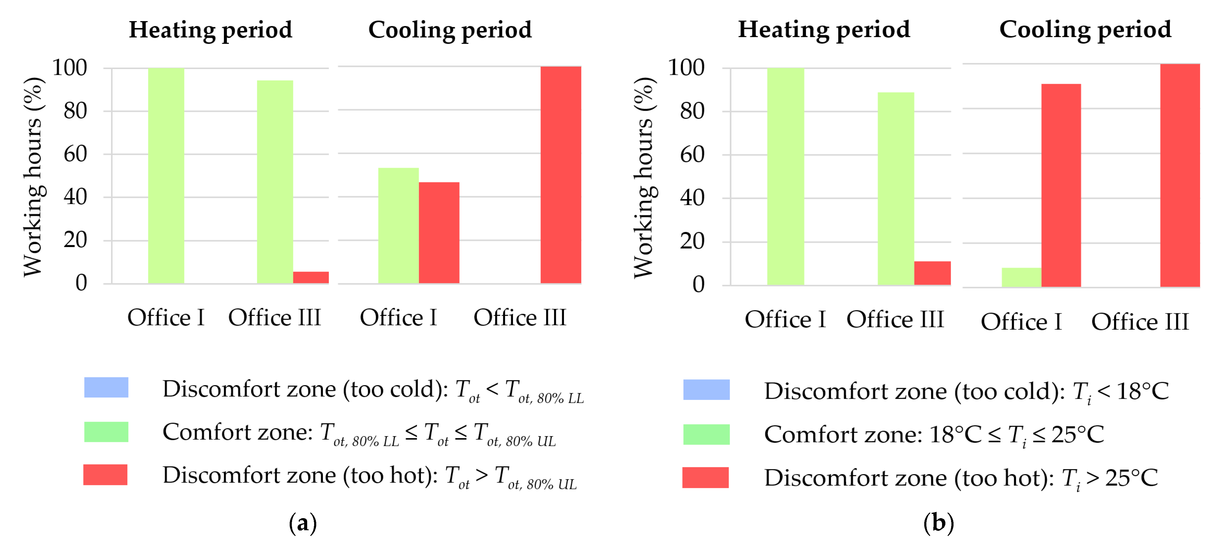
The indoor operative temperature ( T o t ) ranges of the 80% acceptability class (used for typical applications) of the ASHRAE 55 adaptive model [36] and the indoor air temperature ranges present in the Portuguese legislation [37,38,39] were considered for the assessment of the thermal comfort.
The indoor operative temperature, necessary in the ASHRAE 55 adaptive model, was calculated through Equations (1) and (2), where Tmr is the indoor mean radiant temperature and Fp→j is the angle factor between the occupant (p) of the office and the surface (j) [36,40]. The angle factors were calculated assuming that the occupants of the two offices were sitting at the center point of the office floor area. The mean monthly outdoor air temperature ( T o ) was calculated based on the experimental data and then used to calculate the 80% acceptability class limits of the American Society of Heating, Refrigerating and Air-Conditioning (ASHRAE) 55 adaptive model through Equation (3) [36]. The computed indoor operative temperature values were then compared with the 80% acceptability class computed limits ( T o t ,   80 % l i m i t ) and classified according to the following ranges: T o t < T o t ,   80 %   L L (discomfort zone—too cold); T o t ,   80 %   L L T o t T o t ,   80 %   U L (comfort zone); T o t > T o t ,   80 %   U L (discomfort zone—too hot).
T o t = T i + T m r / 2 ,
T m r = j F p j T j
T o t ,   80 % l i m i t = 0.31 × T o + 17.8 ± 3.5
The indoor air temperature experimentally measured in each office was compared with the comfort limits present in the Portuguese legislation [37,38,39] and classified according to the following ranges: T i < 18°C (discomfort zone—too cold); 18°C ≤ T i ≤ 25 °C (comfort zone); T i > 25 °C (discomfort zone—too hot).
Figure 13 shows the computed results of the percentage of working hours within thermal comfort and discomfort for the office rooms for the heating and cooling periods, respectively. The SCF made it possible to increase the percentage of working hours within thermal comfort in office I during the heating period, when compared with the results of office III. During the heating period, the reference office has 6% and 11% of working hours within thermal discomfort (too hot) in accordance with the ASHARE 55 adaptive model [36] and Portuguese legislation [37,38,39] ranges, respectively, which denotes the risk of overheating conditions even during the winter for buildings with large glazed areas in Mediterranean climate regions. During the cooling period, the reference office (office III) has 100% of working hours within thermal discomfort (too hot). The presence of SCF A made it possible to increase by 53% and 9% the percentage of working hours within thermal comfort in accordance with the ASHARE 55 adaptive model [36] and Portuguese legislation [37,38,39] ranges, respectively, during the cooling period.
The visual comfort was assessed in offices I and III, during the weekends of the heating and cooling periods, following two different approaches. For the assessment of the visual comfort during the weekends of the heating period, the indoor horizontal illuminance levels measured at the desk of each office were analyzed in order to account for indoor illuminance levels during different sky conditions (clear and overcast) that are common during the heating season. In addition, the solar elevation angle is lower during the heating period, increasing the potential of glare and, therefore, making the assessment of the absolute values of illuminance collected at the desks, without the artificial lighting on, a suitable way of evaluating visual comfort during this period. For the assessment of the visual comfort during the weekends of the cooling period, indoor illuminance levels were measured at specific times and points of the floor area during a clear sky day, which corresponds to the most dominant and representative sky condition during the cooling season [41]. Furthermore, the solar elevation angle is higher during the cooling period, potentially increasing an asymmetric distribution of the indoor illuminance in the offices and, consequently, making the assessment of the illuminance values experimentally collected across the offices (following a grip of points) an appropriate way to evaluate the visual comfort during this period.
The illuminance levels measured at the desks of offices I and III on the horizontal plane during the weekends of the heating period were grouped into the UDI metric ranges [42] and then the percentage of working hours with these specific ranges was computed in order to assess the indoor visual comfort. The following UDI metric ranges were considered: UDIn—non-sufficient illuminance levels (lower than 0.1 klx); UDIs—supplementary artificial lighting is probably needed to perform visual tasks (between 0.1 and 0.3 klx); UDIa—autonomous illuminance levels without artificial lighting to perform visual tasks (between 0.3 and 3.0 klx); UDIc—useful illuminance levels as the sole source or combined with artificial lighting (between 0.1 and 3.0 klx); UDIe—excessive illuminance levels that can potentially cause overheating and/or glare (higher than 3.0 lx).
Figure 14 shows the percentage of working hours with specific UDI metric ranges at the desk for the two office rooms during weekends (artificial lighting turned off) of the heating period. Office I has a lower percentage (83%) of working hours with useful indoor illuminance levels (UDIc) at the desk comparing with the reference office (97%), due to the highly reflective SCF A installed on the glass.
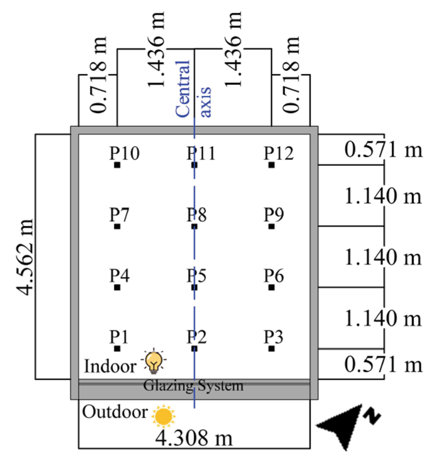
The indoor illuminance levels measured on the work plane (located at 0.7 m above the floor) during a clear sky day of the cooling period were taken in offices I and III (without an SCF) at the following hours: 9 a.m., 12 a.m. and 4 p.m. The location of the measuring points (12 in total), equal in the two offices, is shown in Figure 15.
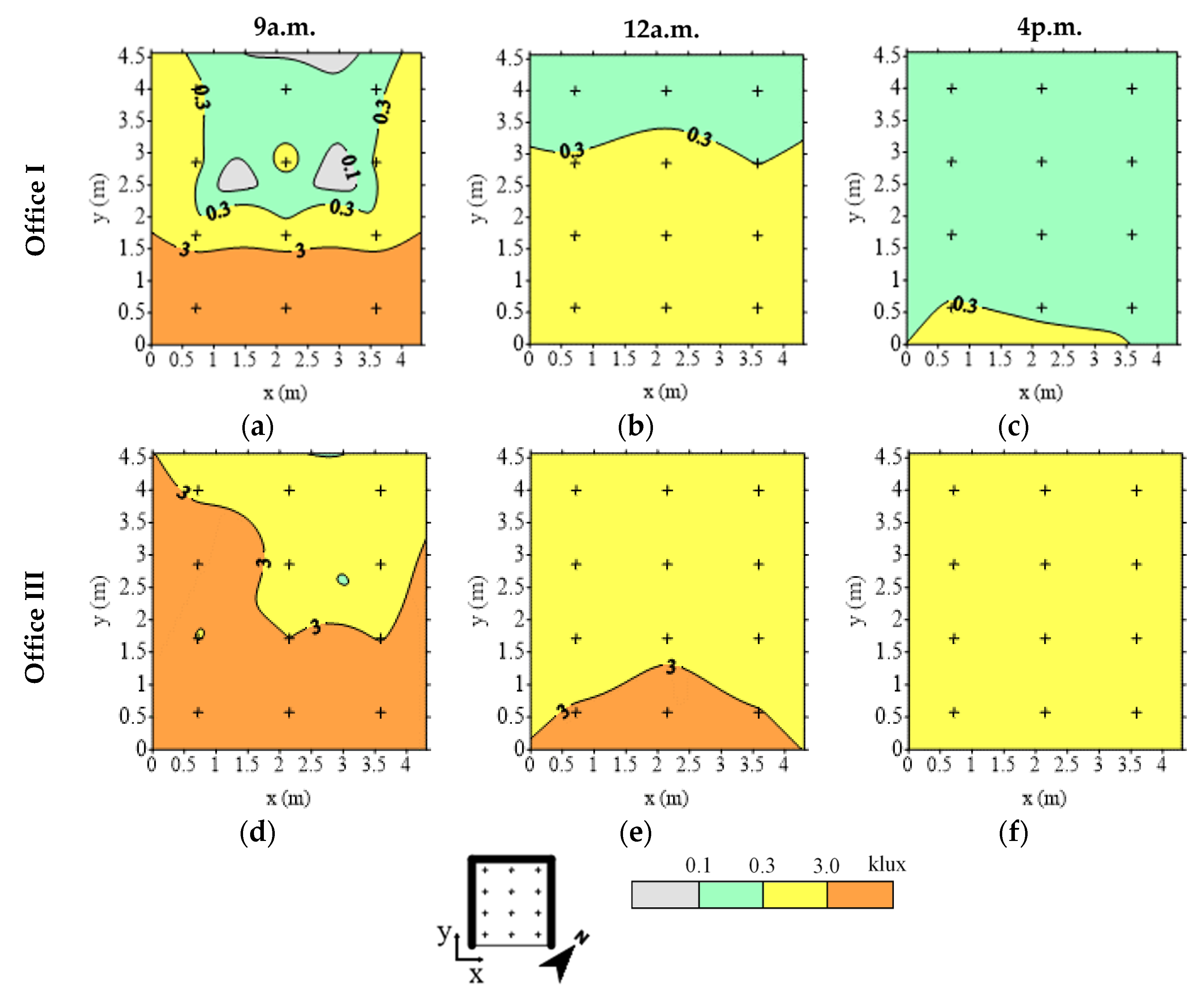
The daylighting levels measured in each office were grouped according to the UDI metric ranges [42] and then mapped (Figure 15). The UDI metric ranges previously considered for the heating period were taken into account, except for the UDIc range.
The office rooms receive direct solar radiation during morning hours, as mentioned in Chapter 2. This can be observed on the indoor illuminance distribution at 9 a.m. shown in Figure 16a where the two offices have illuminance values higher than 3.0 klx (UDIe). The lowest indoor illuminance levels were measured in office I, with the highly reflective film A installed on the external glass surface, because of the low visible transmittance of its glazing system (Table 1). At this time, office I also presents the most significant difference in the luminous distribution across the office floor area, having supplementary (0.1–0.3 klx) and non-sufficient (<0.1 klx) illuminance levels away from the glazing. High values of indoor illuminance were measured in office III (without an SCF), which has the glazing system with the highest visible transmittance, contributing to the occupants’ visual discomfort due to possible glare.
The shading effect on the exterior façade, caused by the protruding wall of the building of the case study, decreased the illuminance levels measured inside the offices at 12 a.m. (Figure 16b). Office I presents lower levels of indoor illuminance when comparing with the reference office (office III), having supplementary illuminance levels in about 25% of the floor area distant from the glazing system. Illuminance values higher than 3.0 klx, possible to cause glare, were measured in office III (without an SCF) in the area closest to the window and between 0.3 and 3.0 klx (UDIa) in the rest of the office area, due to the high visible transmittance of its glazing system.
The indoor illuminance levels at the work plane measured at 4 p.m. are presented in Figure 16c. Office I presents supplementary values of indoor illuminance, making the use of artificial lighting potentially necessary to ensure indoor visual comfort. Office III has autonomous illuminance levels across the office area.

4. Critical Discussion and Limitations

The research findings of the present work suggest that SCFs are more effective in the presence of clear sky conditions (higher outdoor incident solar radiation levels) than of overcast sky conditions (higher outdoor diffuse solar radiation levels). This supports the fact that scientific research and promotion of these window films are more common in hot [20,21,22,24] and temperate [16,17,18,23,25,26,27,28,29,30] climates since they present longer and more severe cooling seasons, successfully promoting the reduction in excessive solar heat gains through the windows.
Similarly to previous findings of research studies reported in the literature review [16,17,18,19,20,21,22,23,24,25,26,27,28,29,30], the installation of SCFs makes it possible to significantly decrease the indoor illuminance levels and temperature values due to the modification of the properties of the glazing system, with a greater emphasis for highly reflective solar control films. However, special attention should be given when choosing SCFs with application to the internal glass surface since it promotes the absorption and consequent reflection of heat towards the indoor environment, increasing the greenhouse effect of the space.
The indoor thermal comfort increased in the presence of SCFs, supporting the results of previous studies [24,25,28,29,30]. Nonetheless, it is important to mention that the comfort performance depends on the thermal standards used as guidelines for the assessment. When assessing the indoor visual comfort, the presence of SCF A reduced excessive daylight levels but increased the potential need for artificial lighting to satisfy the minimum illuminance levels to conduct work tasks.
Overall, the experimental measurements collected during the field campaign and respective analysis made in Chapter 3, “Results”, are consistent with previous scientific experimental studies [16,18,26,27,28,29] reported in the literature review, supporting that the installation of SCFs can promote better thermal and visual performances of the glazing systems of buildings located in hot climates, especially highly reflective SCFs with external application that significantly reduce indoor air temperature and illuminance levels when applied on glazing systems in the Mediterranean climate [29].
The added value of this study to the research topic consists in the fact that the developed work has a more holistic approach that makes it possible to address multiple performance aspects of SCFs, including the impact of these films on indoor comfort, comparing with other studies previously reported in the literature review. The results of the work are the outcome of an extended field experimental campaign that was conducted in post-occupancy conditions, providing real performance data and expressing the impact of SCFs on the indoor environment under real occupancy conditions in the office rooms of the case study. Moreover, the present work helps to fill research gaps due to the scarce studies of the topic in the Mediterranean climate, increasing the scientific knowledge about solar control films through the collection of experimental data on their performance in this temperate climate with very contrasting meteorological conditions during the heating and cooling seasons.
The proposed methodology could be applied in other studies on the luminous and thermal performances of glazing systems, either with or without coatings, and for this reason it can be used to assess the performance of glazing systems with other solar control films and under different climate conditions than the ones of the present work.
Finally, it is important to state that the results and conclusions that emerged from the proposed methodology (Section 2) were influenced by the following limitations that acted as constraints to the generalization of research findings: specific climate (hot-summer Mediterranean climate); specific room and glazing system geometry; specific solar orientation of the glazing systems (southeast); specific solar control films; type and efficiency of existing climatization systems; required comfort conditions. In order to enrich research findings on the performance assessment of glazing systems with SCFs and promote the comparison, connection and globalization of results obtained under distinct assessment conditions, a future analysis should be conducted, diminishing research limitations by covering the following potential studies:
  • Influence of the following variables on the performance of glazing systems with SCFs: solar orientation; type, configuration and control of shading systems; climate conditions.
  • Comparative analysis between the computed indoor comfort and post-occupancy evaluation surveys with occupants’ satisfaction scores.
  • Performance, economic and environmental comparative analysis of installation of SCFs versus the following hypotheses: replacement of the existing glazing for a new glazing with an equivalent performance to the system’s glazing film; shading systems with different optical and thermal properties, and control modes; installation of innovative smart window films with a dynamic behavior that can adapt/react to environmental stimuli.

5. Conclusions

An experimental campaign was conducted simultaneously in three adjacent office rooms, in Lisbon (Mediterranean climate), during heating and cooling periods, to assess the thermal and luminous performances of double-glazing units with and without solar control films (SCFs) in post-occupancy conditions. Office I had a highly reflective SCF (SCF A) installed on the external glass surface of the glazing, office II had a reflective SCF (SCF B) installed on the internal glass surface of the glazing and office III was used as the reference office with the original double-glazing system (without an SCF). The SCFs significantly decreased the solar heat gain coefficient and the transmittance (solar, visible and UV) of the glazing systems, according to the thermal and optical properties computed using Optics and Window [34] software. The indoor mean air temperature and the surface temperature of the glazing systems, both experimentally measured, were used to assess the thermal performance of each glazing. The indoor illuminance levels experimentally measured were used to evaluate the luminous performance of the three glazing systems. Moreover, the field data were also used, along with different metrics and standards [36,37,38,39], [42], to evaluate the influence of the SCFs on the visual and thermal comfort inside the offices.
Based on the assessment of the experimental results of the thermal and luminous performances, the following can be concluded:
  • The indoor air temperature was lower in the offices with SCFs, with reductions in the peak temperature up to 6.9 and 2.3 °C on the representative days of the heating and cooling periods, respectively, in office I when compared with the reference office. Average indoor temperatures of 22.2 and 25.5 °C were obtained in office I during working hours of the coldest and hottest days, respectively, significantly lower than the ones measured in the reference office (coldest day—25.1°C; hottest day—28.9°C). A lower thermal performance was obtained with SCF B installed on the internal glass surface, since it reflects radiation inside and consequently increases the indoor temperature.
  • The indoor illuminance levels measured on the vertical plane in the offices were significantly reduced in the presence of SCFs, with a percentage reduction between 94 and 96% during the sun hours period of the representative days of the heating and cooling periods in office I with the highly reflective SCF A when comparing with the reference office (without an SCF). The measured values were lower than what was expected from the computed optical properties of the glazing systems. The illuminance levels were lower than 0.47 and 1.8 klx in offices I and II, respectively, during 50% of the working hours of the day with the highest levels of outdoor solar radiation levels.
The experimental results collected during the working hours of weekends were used to assess the thermal and visual indoor comfort in offices I and III which have the most and least reflective glazing systems, respectively. Based on these results the following conclusions can be drawn:
  • Office I had 100% of working hours within thermal comfort during the heating period. The presence of SCF A increased the percentage of working hours within thermal comfort during the cooling period, making it possible to obtain thermal comfort during 53% and 9% of the working hours (which corresponds to an increase of 53% and 9% of working hours within thermal comfort when compared with office III), in accordance with the ASHRAE 55 80% acceptability class [36] and Portuguese legislation [37,38,39], respectively.
  • The reference office (office III, without an SCF) has the highest percentage of working hours (97%) within visual comfort during the heating period. The glazing system of office I with SCF A significantly decreased the excessive illuminance levels during the cooling period, increasing visual comfort.
The experimental data and respective conclusions are consistent with previous experimental studies [16,18,26,27,28,29] and help to enrich the scientific knowledge of the performance assessment of glazing systems with SCFs of commercial buildings with large glazed façades, located in a hot-summer Mediterranean climate, using an in-service monitoring approach. The present study made it possible to better understand the effect of SCFs on indoor comfort conditions, complementing previous research studies [24,29].

Author Contributions

Conceptualization, M.d.G.G. and A.M.R.; methodology M.d.G.G., A.M.R., H.T. and J.P.; investigation, H.T., M.d.G.G., A.M.R. and J.P.; supervision, M.d.G.G. and A.M.R.; writing—original draft, H.T.; writing—review and editing M.d.G.G., A.M.R. and J.P. All authors have read and agreed to the published version of the manuscript.

Funding

The first and fourth authors want to acknowledge the support of FCT (Fundação para a Ciência e a Tecnologia) for, respectively, the PhD Grants FCT PD/BD/150576/2020 and PD/BD/127848/2016.

Institutional Review Board Statement

Not applicable.

Informed Consent Statement

Informed consent was obtained from all subjects involved in the study.

Data Availability Statement

The data presented in this study are available on request from the corresponding author.

Acknowledgments

The authors would like to express their thanks to the occupants of the case study office rooms (DEM-IST) for supporting the study and to David Lourenço for conducting the experimental campaign. The authors would also like to express their thanks to the IMPERSOL Company for the technical support.

Conflicts of Interest

The authors declare no conflict of interest.

References

  1. Calama-González, C.M.; Suárez, R.; León-Rodríguez, Á.L. Thermal and Lighting Consumption Savings in Classrooms Retrofitted with Shading Devices in a Hot Climate. Energies 2018, 11, 2790. [Google Scholar] [CrossRef] [Green Version]
  2. Krstić-Furundžić, A.; Vujošević, M.; Petrovski, A. Energy and Environmental Performance of the Office Building Facade Scenarios. Energy 2019. [Google Scholar] [CrossRef]
  3. Prieto, A.; Knaack, U.; Auer, T.; Klein, T. Passive Cooling & Climate Responsive Façade Design Exploring the Limits of Passive Cooling Strategies to Improve the Performance of Commercial Buildings in Warm Climates. Energy Build. 2018. [Google Scholar] [CrossRef]
  4. Li, J.; Ban, Q.; Chen, X.; Yao, J. Glazing Sizing in Large Atrium Buildings: A Perspective of Balancing Daylight Quantity and Visual Comfort. Energies 2019, 12, 701. [Google Scholar] [CrossRef] [Green Version]
  5. Detsi, M.; Manolitsis, A.; Atsonios, I.; Mandilaras, I.; Founti, M. Energy Savings in an Office Building with High WWR Using Glazing Systems Combining Thermochromic and Electrochromic Layers. Energies 2020, 13, 3020. [Google Scholar] [CrossRef]
  6. Troup, L.; Phillips, R.; Eckelman, M.J.; Fannon, D. Effect of Window-to-Wall Ratio on Measured Energy Consumption in US Office Buildings. Energy Build. 2019. [Google Scholar] [CrossRef]
  7. Chiesa, G.; Acquaviva, A.; Grosso, M.; Bottaccioli, L.; Floridia, M.; Pristeri, E.; Sanna, E.M. Parametric Optimization of Window-to-Wall Ratio for Passive Buildings Adopting a Scripting Methodology to Dynamic-Energy Simulation. Sustainability 2019, 11, 3078. [Google Scholar] [CrossRef] [Green Version]
  8. Murano, G.; Primo, E.; Corrado, V. The Effect of Glazing on NZEB Performance. Energy Procedia 2018, 148, 320–327. [Google Scholar] [CrossRef]
  9. Moret Rodrigues, A.; Santos, M.; Gomes, M.G.; Duarte, R. Impact of Natural Ventilation on the Thermal and Energy Performance of Buildings in a Mediterranean Climate. Buildings 2019, 9, 123. [Google Scholar] [CrossRef] [Green Version]
  10. Gomes, M.G.; Rodrigues, A.M.; Bogas, J.A. Numerical and Experimental Study of the Optical Properties of Venetian Blinds. J. Build. Phys. 2012. [Google Scholar] [CrossRef]
  11. Gomes, M.G.; Santos, A.J.; Rodrigues, A.M. Solar and Visible Optical Properties of Glazing Systems with Venetian Blinds: Numerical, Experimental and Blind Control Study. Build. Environ. 2014, 71, 47–59. [Google Scholar] [CrossRef]
  12. Sghiouri, H.; Mezrhab, A.; Karkri, M.; Naji, H. Shading Devices Optimization to Enhance Thermal Comfort and Energy Performance of a Residential Building in Morocco. J. Build. Eng. 2018. [Google Scholar] [CrossRef]
  13. Kunwar, N.; Cetin, K.S.; Passe, U.; Zhou, X.; Li, Y. Energy Savings and Daylighting Evaluation of Dynamic Venetian Blinds and Lighting through Full-Scale Experimental Testing. Energy 2020. [Google Scholar] [CrossRef]
  14. Fedorczak-Cisak, M.; Nowak, K.; Furtak, M. Analysis of the Effect of Using External Venetian Blinds on the Thermal Comfort of Users of Highly Glazed Office Rooms in a Transition Season of Temperate Climate-Case Study. Energies 2019, 13, 81. [Google Scholar] [CrossRef] [Green Version]
  15. Atzeri, A.M.; Gasparella, A.; Cappelletti, F.; Tzempelikos, A. Comfort and Energy Performance Analysis of Different Glazing Systems Coupled with Three Shading Control Strategies. Sci. Technol. Built Environ. 2018. [Google Scholar] [CrossRef]
  16. Li, D.H.W.; Lam, J.C.; Lau, C.C.S.; Huan, T.W. Lighting and Energy Performance of Solar Film Coating in Air-Conditioned Cellular Offices. Renew. Energy 2004, 29, 921–937. [Google Scholar] [CrossRef]
  17. Chen, Y.; Hou, G.; Xie, H.; Chan, W. In-Site Experimental Measurement of Energy-Saving Performance for Solar-Control Film on Single Window Glass. In Proceedings of the Sixth International Conference on Indoor Air Quality, Ventilation and Energy Conservation in Buildings: Sustainable Built Environment, Sendai, Japan, 28–31 October 2007; Volume 1, pp. 47–53. [Google Scholar]
  18. Calama-González, C.M.; León-Rodríguez, Á.L.; Suárez, R. Daylighting Performance of Solar Control Films for Hospital Buildings in a Mediterranean Climate. Energies 2019, 12, 489. [Google Scholar] [CrossRef] [Green Version]
  19. Pereira, J.; Gomes, M.G.; Moret Rodrigues, A.; Teixeira, H.; Almeida, M. Small-Scale Field Study of Window Films’ Impact on Daylight Availability under Clear Sky Conditions. J. Facade Des. Eng. 2020, 8, 65–84. [Google Scholar] [CrossRef]
  20. Noh-Pat, F.; Xamán, J.; Álvarez, G.; Chávez, Y.; Arce, J. Thermal Analysis for a Double Glazing Unit with and without a Solar Control Film (SnS-CuxS) for Using in Hot Climates. Energy Build. 2011, 43, 704–712. [Google Scholar] [CrossRef]
  21. Xamán, J.; Pérez-Nucamendi, C.; Arce, J.; Hinojosa, J.; Álvarez, G.; Zavala-Guillén, I. Thermal Analysis for a Double Pane Window with a Solar Control Film for Using in Cold and Warm Climates. Energy Build. 2014, 76, 429–439. [Google Scholar] [CrossRef]
  22. Xamán, J.; Olazo-Gómez, Y.; Zavala-Guillén, I.; Hernández-Pérez, I.; Aguilar, J.O.; Hinojosa, J.F. Thermal Evaluation of a Room Coupled with a Double Glazing Window with/without a Solar Control Film for Mexico. Appl. Therm. Eng. 2017. [Google Scholar] [CrossRef]
  23. Yin, R.; Xu, P.; Shen, P. Case Study: Energy Savings from Solar Window Film in Two Commercial Buildings in Shanghai. Energy Build. 2012, 45, 132–140. [Google Scholar] [CrossRef]
  24. Chaiyapinunt, S.; Phueakphongsuriya, B.; Mongkornsaksit, K.; Khomporn, N. Performance Rating of Glass Windows and Glass Windows with Films in Aspect of Thermal Comfort and Heat Transmission. Energy Build. 2005. [Google Scholar] [CrossRef]
  25. Amirkhani, S.; Bahadori-Jahromi, A.; Mylona, A.; Godfrey, P.; Cook, D. Impact of Low-E Window Films on Energy Consumption and CO2 Emissions of an Existing UK Hotel Building. Sustainability 2019, 11, 4265. [Google Scholar] [CrossRef] [Green Version]
  26. Li, D.H.W.; Lam, T.N.T.; Wong, S.L.; Tsang, E.K.W. Lighting and Cooling Energy Consumption in an Open-Plan Office Using Solar Film Coating. Energy 2008, 33, 1288–1297. [Google Scholar] [CrossRef]
  27. Li, C.; Tan, J.; Chow, T.T.; Qiu, Z. Experimental and Theoretical Study on the Effect of Window Films on Building Energy Consumption. Energy Build. 2015, 102, 129–138. [Google Scholar] [CrossRef]
  28. Moretti, E.; Belloni, E. Evaluation of Energy, Thermal, and Daylighting Performance of Solar Control Films for a Case Study in Moderate Climate. Build. Environ. 2015, 94, 183–195. [Google Scholar] [CrossRef]
  29. Pereira, J.; Gomes, M.G.; Rodrigues, A.M.; Almeida, M. Thermal, Luminous and Energy Performance of Solar Control Films in Single-Glazed Windows: Use of Energy Performance Criteria to Support Decision Making. Energy Build. 2019, 198, 431–443. [Google Scholar] [CrossRef]
  30. Teixeira, H.; Gomes, M.G.; Moret Rodrigues, A.; Pereira, J. Thermal and Visual Comfort, Energy Use and Environmental Performance of Glazing Systems with Solar Control Films. Build. Environ. 2020, 168, 106474. [Google Scholar] [CrossRef]
  31. European Commission. Indoor Air Pollution: New EU Research Reveals Higher Risks than Previously Thought. Available online: https://ec.europa.eu/commission/presscorner/detail/en/IP_03_1278 (accessed on 10 April 2020).
  32. Reis, C.; Lopes, A. Evaluating the Cooling Potential of Urban Green Spaces to Tackle Urban Climate Change in Lisbon. Sustainability 2019, 11, 2480. [Google Scholar] [CrossRef] [Green Version]
  33. Lourenço, D.L. Experimental Study on the Thermal and Optical Performance of Glazing Systems with Solar Control Window Films. Master’s Thesis, Department of Civil Engineering, Architecture and Georesources, Instituto Superior Técnico, Universidade de Lisboa, Lisboa, Portugal, 2016. (In Portuguese). [Google Scholar]
  34. Curcija, C.; Vidanovic, S.; Hart, R.; Jonsson, J.; Mitchell, R. WINDOW Technical Documentation; Wind. Envel. Mater. Group, Ed.; Lawrence Berkeley Natl. Lab.: Berkeley, CA, USA, 2018. [Google Scholar]
  35. ISO. ISO Standard 7730: Ergonomics of the Thermal Environment—Analytical Determination and Interpretation of Thermal Comfort Using Calculation of the PMV and PPD Indices and Local Thermal Comfort Criteria; International Organization for Standardization: Geneva, Switzerland, 2005. [Google Scholar]
  36. ASHRAE. ASHRAE Standard 55-2017: Thremal Environmental Conditions for Human Occupancy; Am. Soc Heating Refrig. Air-Conditioning Eng.: Atlanta, GA, USA, 2017. [Google Scholar]
  37. Regulamento de Desempenho Energético Dos Edifícios de Habitação (REH), Decree-Law 118/2013 of 20 of August 2013. Diário República 2013, 159, 4988–5005.
  38. Order 15793-K of 2 of December 2013. Diário República 2013, 234, 35088-(58)–35088-(87).
  39. Order 349-B/2013 of 29 of November 2013. Diário República 2013, 232, 6624-(18)–6624-(29).
  40. ISO. ISO Standard 7726: Ergonomics of the Thermal Environment—Instruments for Measuring Physical Quantities; International Organization for Standardization: Geneva, Switzerland, 1998. [Google Scholar]
  41. Moura, P.S.; de Almeida, A.T. Methodologies and Technologies for the Integrations of Renewable Resources in Portugal. In Conference: Renewable Energy World Europe 2009; Department Electrical & Computer Engineering University of Coimbra Portugal: Coimbra, Portugal, 2009. [Google Scholar]
  42. Mardaljevic, J.; Andersen, M.; Roy, N.; Christoffersen, J. Daylighting metrics: Is there a relation between usefuldaylight illuminance and daylight glare probability. In First Building Simulation and Optimization Conference; IBPSA: Loughborough, UK, 2012; pp. 189–196. [Google Scholar]
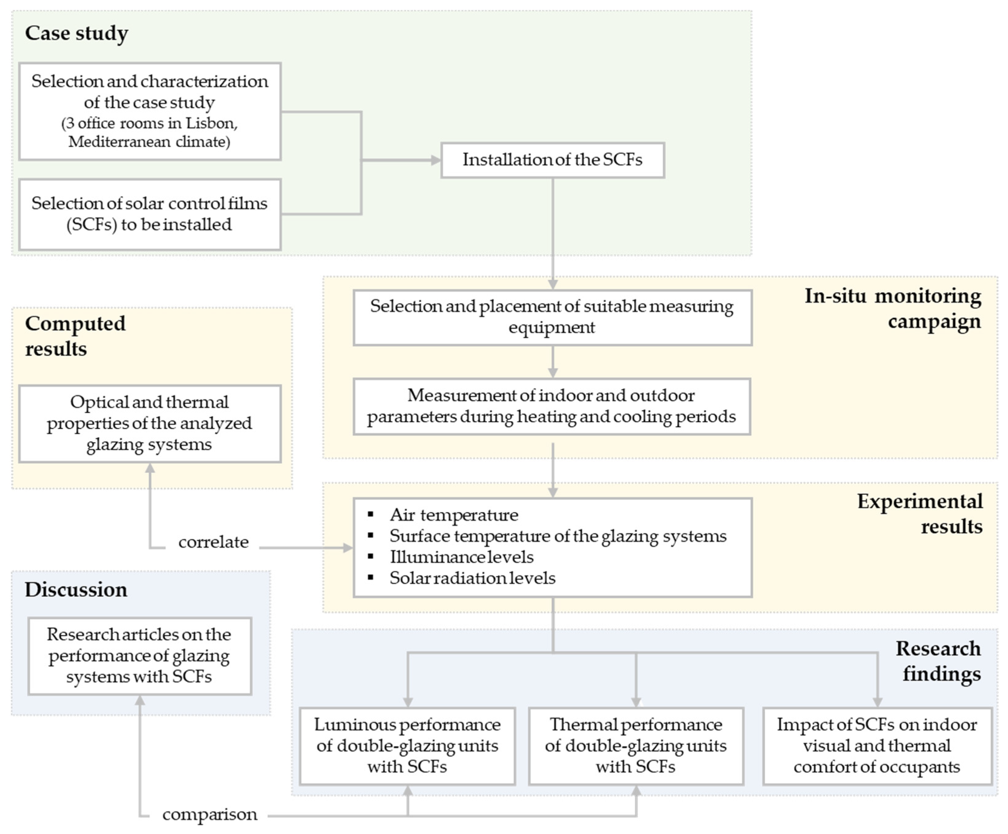
Figure 1. Block diagram with the proposed research.
Energies 14 01388 g001
Figure 2. Block diagram with the proposed methodology.
Energies 14 01388 g002
Figure 3. Office rooms used as case study: (a) identification in dark blue of the location of the three office rooms in the university building (Google Earth 2021); (b) dimensions (length and width) of the office rooms; (c) location (in dark blue) of the glazing systems of the office rooms on the exterior façade (oriented southeast).
Energies 14 01388 g003
Figure 4. Internal view of the removal of the existent solar control film (SCF) and installation of the new SCF in office I: (a) removal of the existing SCF B (internally applied on the glazing); (b) cleaning works of the external glass surface of the glazing; (c) installation of SCF A on the glazing (external glass surface).
Energies 14 01388 g004
Figure 5. Glazing systems analyzed during the experimental campaign: (ac) configuration of the glazing units with and without solar control films ((a): office I with SCF A; (b): office II with SCF B; (c): office III without SCF); (df) solar transmittance and reflectance (%) of the glazing systems computed using Optics software ((d): office I with SCF A; (e): office II with SCF B; (f): office III without SCF).
Energies 14 01388 g005
Figure 6. Location (in the reference office and on the flat roof) of the measuring equipment used in the experimental campaign: (a) south view; (b) east view; (c) glazing system outdoor view (southeast); (d) indoor view of the office room; (e) legend of the representation of the experimental equipment.
Energies 14 01388 g006
Figure 7. Equipment used during the experimental campaign: (a) type-T thermocouple located at the side of the closet (office III) to measure the indoor air temperature; (b) LI-200R pyranometer located at the façade of office III to measure the outdoor solar radiation on the vertical plane (normal to the façade); (c) LI-210R luxmeter located at the side of the closet (office III) to measure the indoor illuminance levels on the vertical plane (normal to the glazing system); (d) CMP6 (left) and BF5 (right) pyranometers located at the top floor to measure the outdoor solar radiation on the vertical (normal to the façade) and horizontal (normal to the top floor) planes, respectively; (e) DL2 data logger used for the data acquisition in office II; (f) position of the shading system during the experimental campaign.
Energies 14 01388 g007
Figure 8. Experimental results of the hygrothermal performance of the offices based on data of working hours (between 9 a.m. and 6 p.m.) from days when the variable refrigerant volume (VRV) unit was turned on (weekdays—(a,c)) and off (weekends—b,d) in the heating (a,b) and cooling (c,d) periods, using a color legend (e): indoor air temperature, T i ; shading slats surface temperature, T s s ; internal glass surface temperature, T s i ; external glass surface temperature, T s e ; relative humidity, R H i n .
Energies 14 01388 g008
Figure 9. Experimental results for the heating period representative days: (a) indoor air temperature, T i ; (b) shading slats temperature, T s s ; (c) internal surface temperature of the glazing systems, T s i ; (d) external surface temperature of the glazing systems, T s e ; (e) legend.
Energies 14 01388 g009
Figure 10. Indoor illuminance levels on the vertical plane in the office rooms for the heating period representative days: (a) relative percentage (%) compared with the reference office room III without SCF; (b) cumulative frequency of working hours (9 a.m. to 6 p.m.) with less than certain levels of indoor illuminance, in %.; (c) legend.
Energies 14 01388 g010
Figure 11. Experimental results for the cooling period representative days: (a) indoor air temperature, T i ; (b) shading slats temperature, T s s ; (c) internal surface temperature of the glazing systems, T s i ; (d) external surface temperature of the glazing systems, T s e ; (e) legend.
Energies 14 01388 g011
Figure 12. Indoor illuminance levels on the vertical plane in the office rooms for the cooling period representative days: (a) relative percentage (%) compared with the reference office room III without SCF; (b) cumulative frequency of working hours (9 a.m. to 6 p.m.) with less than certain levels of indoor illuminance, in %.
Energies 14 01388 g012
Figure 13. Percentage of working hours within thermal comfort inside office rooms I and III during the days with the VRV unit turned off (weekends): (a) ASHRAE 55 adaptive model, with 80% acceptability; (b) Portuguese legislation.
Energies 14 01388 g013
Figure 14. Percentage of working hours within specific indoor illuminance levels (UDI ranges) measured at the desk (horizontal plane) for the office rooms I and III during the days with the artificial lighting turned off (weekends) of the heating period.
Energies 14 01388 g014
Figure 15. Location of the indoor daylight measuring points.
Energies 14 01388 g015
Figure 16. Mapping of the indoor daylight levels (UDI metric ranges) on the work plane, measured on a clear sky day during the cooling period: (ac) office I with SCF A (a: 9 a.m; b: 12 a.m.; c: 4 p.m.); (df) office III without SCF (d: 9 a.m.; e: 12 a.m.; f: 4 p.m.).
Energies 14 01388 g016
Table 1. Optical and thermal properties of the analyzed glazing systems that were computed with Optics and Window software (glazing systems arranged by increasing visible transmittance): thermal transmittance, U-value; solar heat gain, g; visible transmittance, τ v i s ; visible front, ρ v i s F , and back, ρ v i s B , reflectance; solar transmittance, τ s o l ; solar front, ρ s o l F , and back, ρ s o l B , reflectance; ultraviolet transmittance, τ U V ; absorptance of the external, α 1 , and internal, α 2 , glass panes; thermal emissivity of the external, ε E , and internal, ε I , glazing surfaces; spectral selectivity ( τ v i s / g ), SS.
SCFP a U -value
(W/m2K)
g
(-)
τ v i s
(%)
ρ v i s F
(%)
ρ v i s B
(%)
τ s o l
(%)
ρ s o l F   ( % ) ρ s o l B ( % ) τ U V
(%)
α 1
(%)
α 2 ( % ) ε E ( % ) ε I ( % ) S S
(-)
Ae2.710.15166258106344 < 0.126180841.07
Bi2.630.40264546183650 < 1.0143284740.65
W/o b-2.720.7681151570131354.012684841.07
a Position of the film: i—internal glass surface; e—external glass surface. b Without SCF.
Table 2. Experimental equipment used during the extended field experimental campaign and field measured parameters.
EquipmentModelParameterNameAccuracyLocation
ThermocouplesType-TTemperature T i   ;   T o u t ±0.2 °C at 100 °CIndoor and outdoor environments
T s i   ;   T s e Internal and external surfaces of the glazing systems
T s s Slats surface
BF5
(DeltaT)
Solar radiation
Diffuse
(horizontal plane)
I d i f f , h ±20 W/m2 ± 15%Flat roof
Global
(horizontal plane)
I g l o b a l , h ±5 W/m2 ± 12%Flat roof
LI-200R
(LICOR)
Global
(vertical plane)
I f a c a d e , v ±3%Office III façade
CMP6
(Kipp&Zonen)
Global
(vertical plane)
I r o o f , v 5 to 20 µV/W/m2Flat roof
LuxmeterLI-210R
(LICOR)
Illuminance
(horizontal plane)
E r o o f , h ±5%Flat roof
(vertical plane) E i , v Side of the closet
HOBO sensorU12-012
(HOBO)
Temperature T d e s k ±0.35 °C; ±2.5%Desk
Relative humidity R H i
Illuminance
(horizontal plane)
E i , h
Table 3. Experimental results of the visible performance ( E i , v ) of the offices based on data of working hours (between 9 a.m. and 6 p.m.) from days when the VRV unit was turned on (weekdays) and off (weekends) in the heating and cooling periods.
PeriodOffice (SCF)WeekdaysWeekends
x ¯ (lx) Δ E E W / o   S C F a ( % ) x ¯ (lx) Δ E E W / o   S C F a ( % )
Heating PeriodOffice I (SCF A)58394.348594
Office II (SCF B)136183.7110583.7
Office III (W/o SCF)10.660-7488-
Cooling PeriodOffice I (SCF A)60193.264886.9
Office II (SCF B)171580.4163372.5
Office III (W/o SCF)4013-7608-
a Relative percentage reduction compared with the reference office room without SCF (office III).
Table 4. Average, x ¯ , and maximum, M, measured values of the outdoor air temperature, T o u t , and of the outdoor global solar radiation measured at the reference office façade on the vertical plane, I f a c a d e , v , during the sun hours period of the heating and cooling periods’ representative days (heating period: Dcoldest, Dw/oC-H and Drad; cooling period: Dhottest, Dw/oC-C and DRAD).
ParameterHeating PeriodCooling Period
DcoldestDw/oC-HDradDhottestDw/oC-CDRAD
T o u t (°C) x ¯ 15.1114.8115.4130.6426.7527.90
M20.1919.0116.3937.1733.5434.42
I f a c a d e , v   (W/m2) x ¯ 92.9846.9011.3867.4765.2582.50
M234.59220.1845.55166.05167.44210.47
Publisher’s Note: MDPI stays neutral with regard to jurisdictional claims in published maps and institutional affiliations.