Article

Nyström Minimum Kernel Risk-Sensitive Loss Based Seamless Control of Grid-Tied PV-Hybrid Energy Storage System

1
Department of Electrical Engineering, NIT Srinagar, Srinagar 190006, India
2
Department of Electrical Engineering, University of Kashmir, Srinagar 190006, India
3
Marine Engineering Technology in a Joint Appointment with Electrical and Computer Engineering, Texas A&M University, Galveston, TX 7553, USA
4
School of Electrical Engineering Computing and Mathematical Sciences, Curtin University, Perth, WA 6845, Australia
*
Author to whom correspondence should be addressed.
Energies 2021, 14(5), 1365; https://doi.org/10.3390/en14051365
Submission received: 28 December 2020 / Revised: 18 February 2021 / Accepted: 24 February 2021 / Published: 2 March 2021

Abstract

:
This paper presents Nyström minimum kernel risk-sensitive loss (NysMKRSL) based control of a three-phase four-wire grid-tied dual-stage PV-hybrid energy storage system, under varying conditions such as irradiation variation, unbalanced load, and abnormal grid voltage. The Voltage Source Converter (VSC) control enables the system to perform multifunctional operations such as reactive power compensation, load balancing, power balancing, and harmonics elimination while maintaining Unity Power Factor (UPF). The proposed VSC control delivers more accurate weights with fewer oscillations, hence reducing overall losses and providing better stability to the system. The seamless control with the Hybrid Energy Storage System (HESS) facilitates the system’s grid-tied and isolated operation. The HESS includes the battery, fuel cell, and ultra-capacitor to accomplish the peak shaving, managing the disturbances of sudden and prolonged nature occurring due to load unbalancing and abnormal grid voltage. The DC link voltage is regulated by tuning the PI controller gains utilizing the Salp Swarm Optimization (SSO) algorithm to stabilize the system with minimum deviation from the reference voltage, during various simulated dynamic conditions. The optimized DC bus control generates the accurate loss component of current, which further enhances the performance of the proposed VSC control. The presented system was simulated in the MATLAB 2016a environment and performed satisfactorily as per IEEE 519 standards.

1. Introduction

Grid integrated photovoltaic (PV) systems are gaining substantial significance in the modern grid scenario. The PV power generation rose 22% (+131 TWh) in 2019, to 720 TWh as the second-highest absolute generation, slightly behind wind and ahead of hydropower plants [1]. Despite the global slowdown of 2020, PV is expected to grow 15% annually from 720 TWh to almost 3300 TWh in 2030 [2]. Moreover, the world is expecting CO2 emission reductions from 33.5 Gt to 20 Gt by the year 2030 [3,4].
The voltage source converter (VSC) controls based on conventional, adaptive, predictive, and artificial intelligence (AI) techniques have been implemented on a grid-tied PV system. The synchronous reference frame (SRF) and power balance theory [5] controls have been extensively used for grid-tied PV systems. Researchers have implemented various adaptive VSC controls, such as least mean square (LMS) [6], which uses a fixed step-size for adaptation to find the balance between the convergence equation and maladjustment error results at low-convergence speed and larger steady-state oscillations. The least mean fourth (LMF) algorithm [7] acts as a higher-order adaptive filter for better mean square error (MSE) reduction with fixed step-size. The power normalized KLMS (PNKLMS) [8] utilizes the power kernel for fundamental current component extraction with reduced computational burden. The analysis of variance (ANOVA) kernel Kalman algorithm (AKK) [9] is the hybridization of the Kalman filter and kernel trick, which significantly reduces the algorithm delay and complexity. The normalized Laplacian kernel adaptive Kalman algorithm (NLKAK) [10] is a Laplacian kernel that is combined with an estimator process for pattern reorganization. The KAF methods utilize the MSE as a cost function, which provides adequate accuracy, stability, and convergence rates with Gaussian noises. More robust adaptive algorithms, such as maximum correntropy criteria (MCC) [11], which is a biased estimator, utilizes the Gaussian kernel for better mean square stability. The reweighted zero-attracting MCC (RZA-MCC) [12] enhances the performance of MCC with a zero-attracting algorithm resulting in a better convergence rate and reduced harmonics level. The variable parameter zero-attracting LMS (VPZALMS) [13] uses an adaptive coefficient to smooth out the transients, which results in better performance. The kernel risk-sensitive loss (KRSL) [14] is where the cost function is made insensitive towards heavy-tailed Gaussian noises. The proposed control based on the Nyström minimum kernel risk-sensitive loss (NysMKRSL) [15] algorithm with a linear growth network can manage both Gaussian and non-Gaussian noises with high filtering accuracy and robustness, as compared to other adaptive control algorithms. In the model predictive controls (MPC), the cost function parameter selection is vital for system performance. The finite control set MPC (FCSMPC) [16] is the optimization based control of the inverter. The weighting factor design based MPC (WFDMPC) [17] utilizes automated weights of cost functions for better performance, which have been utilized for VSC control. AI techniques such as an artificial neural network (ANN) [18] and adaptive network-based fuzzy interface system (ANFIS) [19] have been utilized in micro-grids.
The VSC control enables it to perform multifunctional operations, including reactive power compensation, power quality enhancement, load, and power balancing while maintaining unity power factor (UPF). The VSC performs multifunctional operations during steady-state and various dynamic states, i.e., irradiation variation, load unbalancing [20,21], grid voltage sag and swell, and fixed power mode.
The grid-tied PV system may face an islanding problem during very low solar irradiation levels (low PV power yield), under and over-grid voltages, or frequency fluctuations, curbing the effect of grid faults and system maintenance [22,23]. The grid islanding condition should be quickly detected and eliminated by seamlessly re-synchronizing the grid. Several VSC controlling strategies and topologies have been proposed by researchers for seamless control, such as in [24] where the same control loop is utilized in grid-tied and islanded mode. In [25], indirect control strategies involve a current control loop that regulates grid current by providing a reference voltage to the voltage control loop. In [26], the grid-tied mode is controlled by droop control or integral control, whereas in islanded mode, nominal voltage and frequency values are regulated. In [27], VSC and current source converter (CSC) are utilized to achieve seamless control. In [28], a quasi proportional and multi-resonant grid synchronization scheme is presented. In [29], a voltage control strategy is used in both grid-tied and islanded mode with a D-module filter to extract the positive sequence voltage component. In [30], a current controller regulates the grid current, and a voltage controller handles the filter capacitance in the grid-tied mode. Whereas, during grid-islanded mode, the voltage controller regulates the output voltage.
The hybrid energy storage system (HESS) consisting of energy storage elements of contrasting characteristics provides the ability to manage disturbances of sudden, intermediate, and prolonged nature, i.e., faults, voltage sag, and swell. The ultracapacitor (UC) and lead-acid battery with ultra-high and high-power density, respectively, can provide a high amount of power in a short span for a small duration [31,32]. In comparison, the proton exchange membrane fuel cell (PEMFC) has high energy density, which can provide power for a longer duration without considerable change in load profile [33,34]. For better PV power utilization, a dual battery storage system is presented in [35]. The PV-HESS system can operate in both grid-tied and islanded mode while maintaining the system’s stability and power quality.
The DC bus voltage VDC, on the DC side of the inverter, significantly influences the system stability. The dynamics of PLL, reactive power control of the inverter, and impedance of the grid collectively influence the VDC [36]. Variations in VDC may occur due to the transfer of control from grid-tied mode to isolated mode, solar insolation variation (PV power variation) [37], load unbalancing, and power unbalancing. Several conventional and intelligent controls have been utilized for VDC regulation [38,39]. An optimized energy management system for better efficiency is presented in [40], and battery voltage optimization is presented in [41]. The system performance can further be enhanced by optimizing the PI controller gains by various evolutionary optimization and swarm intelligence techniques, such as genetic algorithm (GA) [42], which have versatile applications and require less information about the problem, although the rate of mutation and crossover as well as the selection criteria affect the outcome. The parallel evolutionary algorithm (PEO) [43] speeds up the convergence rate as compared to other sequential evolutionary algorithms, but it requires a large population size as it produces a large number of results before finding the best solution. Particle swarm optimization (PSO) [44] is simple to understand and implement and delivers better computational efficiency, but it suffers from getting trapped in local minima. Salp swarm optimization (SSO) [45] uses an adaptive mechanism to balance convergence and divergence, hence preventing the stagnation on local minima, and many more [46].
The proposed system is a three-phase four-wire grid-tied dual-stage PV-HESS system. The DC link voltage is regulated by the SSO-tuned PI controller, which generates a more accurate loss component of current (Id1) and delivers better stability. The better Id1 further elevates the performance of the proposed VSC control. The stable DC link voltage helps VSC control to generate more accurate weight signals and reduces overall losses of the system. The VSC control is provided by the NysMKRSL algorithm to facilitate multifaced operation during steady-state and various dynamic states. Seamless control is provided by the grid current control (GCC) during grid-tied mode and voltage control in islanded mode. The HESS consisting of a battery, UC, and PEMFC can handle any disturbance occurring on the proposed system’s PV, load, and grid side. The main contributions of the paper are outlined below.
  • VDC regulation: The DC link voltage is regulated with the gain optimized PI controller based on the SSO algorithm that generates an accurate loss component of current and enhances the stability of the system.
  • Adaptive control of VSC: The NysMKRSL-based VSC control uses excess mean square error (EMSE) as the cost function to speed up the convergence and enhance precision. The optimized DC bus further improves the performance of the proposed control by better extraction of the weight signal and fundamental component of currents.
  • Seamless control: The system facilitates the transition from grid-tied mode to islanding mode to re-synchronization mode without any major transients and disturbances to the system stability.
  • Multifunctional operation of VSC: The VSC will perform the multifunction operations, including reactive power compensation, load and power balancing while maintaining UPF throughout the operation.
  • Dynamic operating conditions: Various dynamic conditions have been induced, such as irradiation variation, load unbalancing, fixed power mode, and grid voltage variation (sag and swell) to analyze the system.
  • HESS: The HESS consisting of lead-acid battery, UC, and PEMFC can manage the system irregularities occurring on the grid, load, and PV side.
The rest of the paper is organized as follows. Section 2 describes the proposed topology. Section 3 presents the implemented control strategies, i.e., VSC control, seamless control, DC-DC bi-directional converter control and SSO optimized DC link voltage control. Section 4 describes the results and discussions of the presented system during various induced dynamic conditions. Section 5 concludes the work.

2. Proposed Topology

The proposed system is a three-phase four-wire grid-tied dual-stage PV-HESS system, as shown in Figure 1. The PV system of 32 kW, with an incremental conductance (InC) method of maximum power extraction [20,21], is utilized. The PV system is connected to the DC bus via boost converter. The HESS consisting of the battery and UC is also attached to the DC bus via a buck-boost bi-directional converter, whereas PEMFC is directly connected at the 700 V DC bus with a unidirectional diode to avoid the reverse power flow. The battery, UC, and PEMFC provide 5.6 kW, 4 kW, and 7 kW backup for 12 h, respectively. The VSC with eight switches in four legs converts the DC power available across the DC-link capacitor to the AC power and makes it available at the point of common coupling (PCC) via interfacing inductor. The interfacing inductor and RC filters are utilized to lessen the excess current ripples. The non-linear load of 17 kW and grid power supply of 415 V (RMS) AC, through the master control switch (MCS), is also connected to the system at PCC. MCS allows the bi-directional flow of current with a unidirectional voltage blocking capability that facilitates intentional islanding.

3. Controlling Strategies
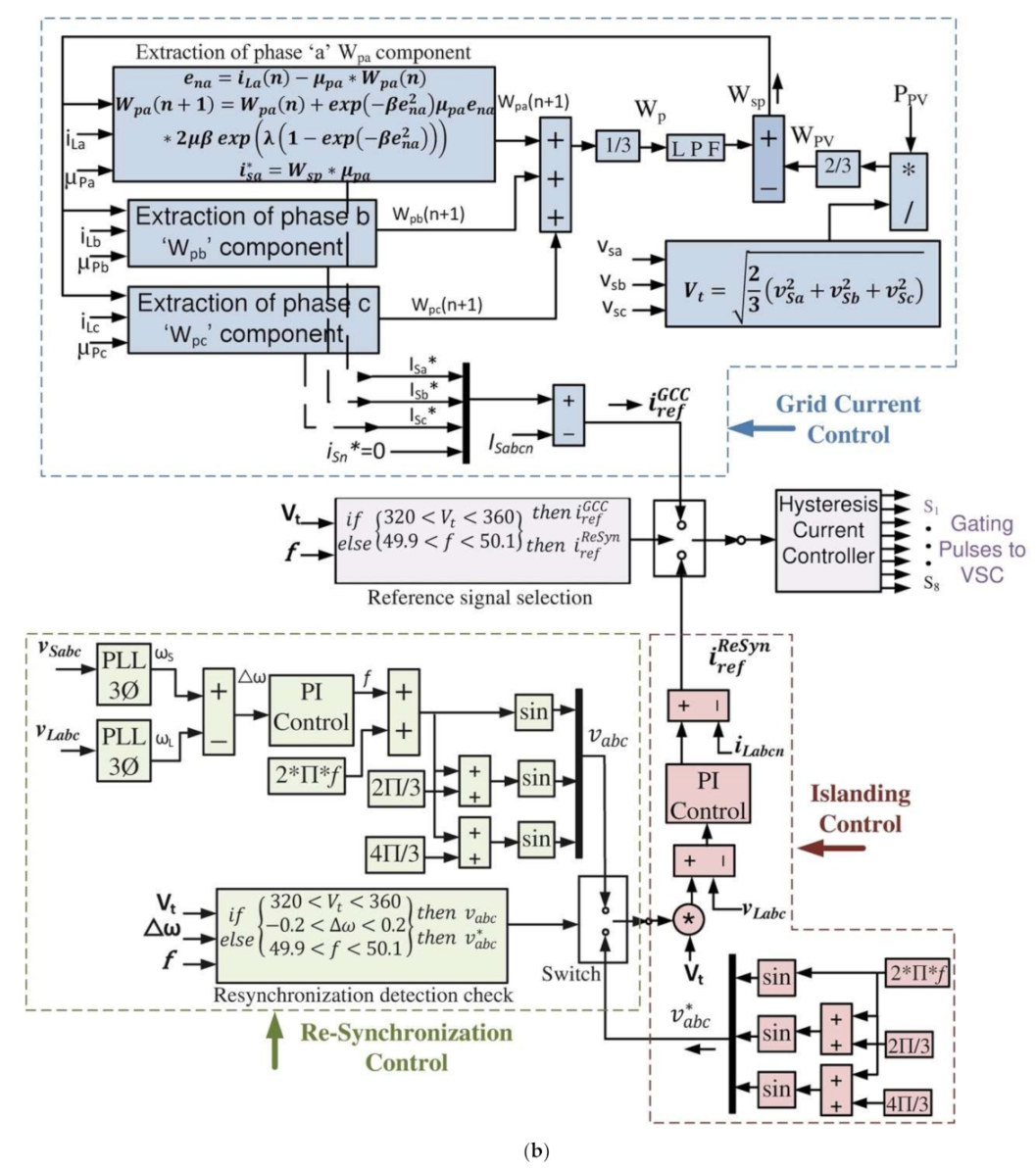
Several controlling strategies have been involved in the presented work, such as InC-based maximum power point tracking (MPPT) control, NysMKRSL-based VSC control, seamless control for islanding and re-synchronization, bi-directional converter control for battery and UC charge control, and VDC control by conventional PI and PI gains optimization by the SSO algorithm. The research methodology utilized in the presented work is shown in Figure 2a, where PV voltage, current ( V PV , I PV ), DC bus voltage ( V DC ), battery, and UC current ( I BAT , I UC ) are sensed for controlling the SSO-based VDC, optimization boost converter, and battery and UC current. The grid voltage, current ( v S a b c , i S a b c ), load current ( i L a b c ), voltage magnitude (Vd), frequency f, and phase angle θ are sensed for proper AC side operation. Three steps to check the mechanisms for islanding detection, grid re-synchronization detection, and grid re-synchronization confirmation are provided for effortless and seamless transition of VSC controls.

3.1. VSC Control

The VSC control is provided by the NysMKRSL algorithm for achieving a higher filtering accuracy and robustness against non-Gaussian noise, as shown in Figure 2b. The minimum kernel risk-sensitive loss (MKRSL) algorithm has a linear growth of network size with each iteration, resulting in a huge computational burden and memory requirement.
The network matrix approximation can be performed by sparsification, vector quantization (VQ), random Fourier feature (RFF), the Nyström method, and many more. The sparsification method reduces the computational accuracy, whereas VQ methods use redundancy data for weight updates. Both methods cannot fix the network size beforehand. The RFF method is based on the random selection of data, so it generates a larger dimension of network structure. The Nyström method generates the fixed network structure with a uniform sampling method that improves accuracy, convergence rate, and reduces the computational burden. The weights of NysMKRSL are generated by a gradient descent method to minimize [15].
In the proposed control, μ p x (x = a,b,c) are the direct phase components of the sensed source voltage vsabc and its voltage magnitude Vd as per (1) [28]. enx (x = a,b,c) are error signals of each phase and are calculated as a function of load current iLabc and extracted weight component of each phase Wpx (x = a,b,c) as per (2). The weight components of each phase Wpx (x = a,b,c) are calculated as per (3), (4), and (5), where β = 1 / 2 σ 2 is the kernel function, σ is the width of the Kernel, μ > 0 is the step size, and λ > 0 is the risk-sensitive parameter. The average of each phase component Wp is negated with the feed-forward term WPV to generate the overall weight component Wsp as per (6) and (7). Wsp is utilized to generate the reference currents i s x * (x = a,b,c). This is further compared with the sensed source currents iSabc and provided to the hysteresis current controller (HCC) to generate the switching sequence for the GCC mode of operation as per (8). During the fixed power mode, each phase weight component will be taken over by W s p f i x and i S a f i x * , i S b f i x * , i S c f i x * are calculated as per (9) and (10).
μ p x = v s x V T ,   where   x   =   a , b , c
e n x = i L x n μ p x W p x n ,   where   x   =   a , b , c
W p a n + 1 = W p a n + e x p β e n a 2 μ p a e n a 2 μ β   e x p λ ( 1 e x p ( β e n a 2 ) )
W p b n + 1 = W p b n + e x p β e n b 2 μ p b e n b 2 μ β   e x p λ ( 1 e x p ( β e n b 2 ) )
W p c n + 1 = W p c n + e x p β e n c 2 μ p c e n c 2 μ β   e x p λ ( 1 e x p ( β e n c 2 ) )
W P V = 2 3 P P V 2 3 v s a 2 + v s b 2 + v s c 2 = 2 3 P P V V T
W s p = W p W P V
i s a * = W s p μ p a ,   where   x   =   a , b , c
W s p f i x = 2 3 P f i x 2 3 v s a 2 + v s b 2 + v s c 2 = 2 3 P f i x V T
i s x f i x * = W s p f i x μ p x ,   where   x   =   a , b , c

3.2. Seamless Control for Islanding and Re-Synchronization

The islanding and re-synchronization controls are shown in Figure 2. The grid can be isolated from the rest of the system by MCS, which is a three-phase switch and allows the bi-directional flow of current during GCC mode [30,31]. The islanding of the system is confirmed by comparing the Vd and frequency f of vsabc with pre-decided standard values. If the islanding condition is confirmed, then the VSC control shifts from GCC mode to islanded control mode. During islanded operation, the product of Vd and the generated reference voltage v a b c * is compared with load voltage vLabc and provided to the PI controller. The reference current signal generated from the PI controller is compared with load current iLabcn and provided to the HCC for VSC control.
Re-synchronization of the grid is initiated when MCS reconnects the grid to the rest of the system. The grid is intentionally isolated for a few cycles until the magnitude, frequency, and phase angle ω s of the grid voltage matches the magnitude, frequency, and phase angle ω L of the load voltage. The phase angle of source and load voltages are compared to produce a change in phase angle Δ ω . Δ ω is provided to the PI controller to generate the f frequency signal, which is utilized to generate the re-synchronization reference voltage vabc. The vabc voltage is utilized to generate the i r e f R e S y n for VSC control. Δ ω plays a pivotal role in grid re-synchronization, without causing major source voltage transients that result in safety and security problems. The frequency matching of load and source voltages requires two to four cycles, and once the re-synchronization is confirmed, the VSC control is seamlessly shifted to the GCC mode [29].

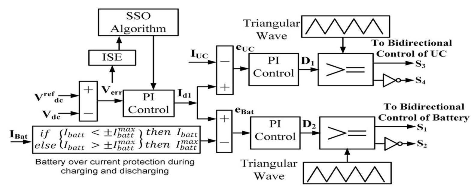
3.3. Bi-Directional Converter Control

The buck-boost bi-directional converters each for battery and UC charging and discharging current control have been employed as shown in Figure 3. The loss component of current (Id1) will be compared with battery current IBat and UC current IUC individually. The batteries are vulnerable against high charging and discharging currents, so the battery over-current protection is also incorporated in control. Comparisons of the IUC and IBat with Id1 as e U C and e B a t are provided to the PI controllers with gains KpUC, KiUC, KpBat, and KiBat to generate the duty cycles D1 and D2 as per (11) and (12) [23].
D 1 n + 1 = D 1 n + K p U C I d 1 I U C + K i U C s I d 1 I U C
D 2 n + 1 = D 2 n + K p B a t I d 1 I B a t + K i B a t s I d 1 I B a t
The duty cycle will be further compared with the triangular signal of 10 kHz for generating the switching sequence for bidirectional converters.

3.4. DC-Link Voltage Control

The DC voltage regulation is presented by PI gains optimized by SSO algorithms [45]. The sensed VDC from the DC-link coupling capacitor is lessened from the reference VDC, i.e., V D C r e f = 695 V. The voltage error Verr is provided to the PI controller to generate the Id1 as per (13). The Id1 is further utilized as the reference current for battery and UC control, as shown in Figure 3.
I d 1 n + 1 = I d n + K p V D C r e f V D C + K i s V D C r e f V D C
The PI controller gains can be optimized for better control of the system. The PI gains K p and K i are tuned by GA and SSO algorithms separately to reduce the VDC variations during various dynamic conditions [42,45]. The performance of the PI controller may be assessed by considering how large the error from the setpoint is. The integral square error (ISE) is calculated as per (14).
I S E = 0 V D C r e f V D C 2 d t = 0 V e r r 2 d t
The ISE serves as the single objective function, which needs to be minimized by implementing GA and SSO for PI gains optimization. GA is one of the most well-known and widely accepted optimization algorithms. The SSO is a bio-inspired algorithm based on the food searching behavior of salps (family of salpidae) in the form of a salps chain, having a transparent barrel-shaped body. The SSO algorithm is initiated with the random population of salps, differentiated as leader and follower salps. The leader salp position is the best solution obtained depending on the food source and further assigned to the follower salps. The leader salp position is updated as per (15) and (16) during the exploration and exploitation phase. Where x j 1 is the position of leader, F j is the position of the food source in dimension j, and u b j ,   l b j are the maximum and minimum limits in dimension j. The coefficient   c 1 balances the convergence and divergence as per (17), and c 2   and   c 3 are the uniformly generated random numbers, where l   and   L represent the current and maximum number of epochs. The followers’ salp position is updated as per (18), where x j i is the follower salp position in dimension j, which gets updated as per leader salp position depending on food position [45]. With Equations (15), (16), and (18) the salp chain can be formed.
x j 1 = F j + c 1 u b j l b j c 1 + l b j   c 3 0
x j 1 = F j c 1 u b j l b j c 2 + l b j   c 3 0
c 1 = 2 e 4 l L 2
x j i = 1 2 x j i + x j i 1 ;   i 2
x j i are the tuned gains of the PI controller, u b j   and   l b j are the lower and upper bounds of PI gains, and the problem is two-dimensional as only proportional and integral gains need tuning.
The SSO algorithm is adaptive with high exploration and exploitation using converging and diverging parameters, minimum feature selection, which results in less computational time and better accuracy. The SSO algorithm is utilized with search agent numbers (N = 30) and the maximum number of iterations (t = 50) to find the gains of the PI controller.

4. Results and Discussion

The proposed system is a NysMKRSL-based VSC control for 32 kW grid-tied dual-stage PV system with HESS. The InC algorithm is used for MPPT and boost converter control, and the SSO algorithm is used for VDC control. The HESS current control is done by the PI controller. The PV, HESS, and fuel cell are attached to the DC bus. The presented system is analyzed under steady-state and various dynamic states such as irradiation variation, load unbalancing, fixed power mode, grid voltage unbalancing (sag and swell), and seamless transition of islanding and re-synchronization in the MATLAB simulation environment.

4.1. Steady-State Performance

The steady-state is simulated with irradiation level fixed at 1000 W/m2 and ambient temperature 25 °C from 0.2 s to 0.26 s simulation time. During steady-state operation the system harmonics level is maintained within the desired limits. The total harmonics distortion (THD) of the vSa, iSa, vLa and iLa are also shown in Figure 4a–d, which are below the permissible limit of 5% and satisfactory as per IEEE519 standards. The VDC is controlled with the help of a PI controller during various induced dynamic conditions. The DC bus stability with the first-order controller is analyzed as non-linear using the bode plot, as shown in Figure 5. The magnitude and frequency plot of the closed-loop DC bus shows the attenuation of DC components and low-frequency components passing through the PI controller.

4.2. Irradiation Variation Mode Performance

The irradiation variation is simulated by reducing the PV insolation level from 1000 W/m2 to 600 W/m2 during the simulation time from 0.45 s to 0.55 s. The source voltage v S a b c will remain the same as the voltage at PCC in grid-tied operation. The source current i S a b c matches with the reference currents i S a * , i S b * , i S c * generated by the proposed VSC control during grid-tied current control mode. The VSC current compensates the load current, verified by phase ‘a’ of load iLa and compensator current iCa as shown in Figure 6. The voltage magnitude Vd is maintained at the desired level during irradiation variation. The load neutral current iLn and compensator neutral current iCn are in phase opposition with each other and revolves at thrice of the fundamental frequency, resulting in the source neutral current iSn being maintained around zero, which is its reference value. With the reduced solar irradiation at 0.45 s, the power delivered to the grid Pg also reduces as with iSabc, which is in phase opposition with vSabc. Pg is following exactly its reference value P g r e f . Likewise, Qg is the reactive power exchange from the grid, maintained around zero, which is its reference value Q g r e f . The VSC satisfies the system’s reactive power requirement and solid-state switches so that the Qg is maintained around zero during the whole operation. On the DC side, the PV voltage VPV is maintained around the V PV ref , which is 600 V, by utilizing the boost converter. The PV current IPV and power PPV decreases accordingly with the changing solar irradiation level and matching with the reference PV power P PV ref and reference PV current I PV ref . The battery current IBAT and UC current IUC are negative, as both are charging due to excess availability of power, and battery voltage VBAT and VUC both are increasing gradually. IBAT and IUC both follow their reference signal, which is depicted as Id1 in Figure 3. The PEMFC is directly connected to the DC bus with voltage VFC and current IFC, as shown in Figure 7. The DC bus voltage VDC is preserved around its reference value V DC ref , which is 700 V with a variation of a few volts only.

4.3. Load Unbalancing Mode Performance

The load unbalancing is simulated by disconnecting the phase ‘a’ of the load from 0.7 s to 0.8 s of simulation time. During load unbalancing iLa reduces to zero, and power delivered to the grid Pg increases while following the P g r e f , with the reduced load requirements. The iSabc matches with the reference source currents i S a * , i S b * , i S c * during the unbalancing load too. The iCa also becomes more sinusoidal with the reduction of non-linear load. The Vd is also kept at the desired level. The iCn and iLn are compensating each other with twice the fundamental frequency during load unbalancing, and iSn is preserved around its zero reference value. Qg exchange with the grid is maintained near zero as Q g r e f because VSC provides the necessary reactive power, as shown in Figure 8. The VPV, IPV, and PPV remain at the same level as a fixed irradiation level as their respective reference values. The battery and UC charging rate increases as the IBAT and IUC follow their reference signal and become more negative. The PEMFC is directly connected to the DC bus at 700 V. The VDC voltage is also maintained around 700 V with the variation of merely a few volts from V DC ref during the unbalancing load, as shown in Figure 9.

4.4. Fixed Power Mode Performance

The fixed power mode is implemented to provide the peak power during the peak demand condition, in which PV, along with HESS, has to satisfy the excess amount of power required by the grid. The fixed power mode is induced by forcing the GCC control of VSC to provide a pre-decided amount of power. The fixed power mode is simulated from 1 s to 1.1 s of simulation time. Pg shows an increased amount of power delivered to the grid, and likewise, a slight increase in iSabc is also visible. iSabc and Pg both are following their respective reference signals. iLa remains the same, but iCa also increases with iSabc. iSn and Qg are maintained at zero as their reference signals, as depicted in Figure 10. On the other hand, VPV, IPV, and PPV remain the same and match their respective references with a fixed irradiation level. IBAT and IUC both have reduced and become less negative. Though the battery and UC are still charging, their charging rate is reduced considerably. The excess power delivered to the grid reduces the charging rate of the battery and UC. The VFC and IFC show no major changes in fixed power mode due to their slow dynamics. The VDC is maintained at 700 V while matching with V DC ref during fixed power mode, as shown in Figure 11.

4.5. Source Voltage Sag and Swell Performance

The source voltage sag and swell of 0.8 p.u. and 1.2 p.u. are simulated from 0.2 s to 0.25 s and 0.25 s to 0.3 s of simulation time. The abnormal grid voltage affects iSabc, which also changes accordingly to maintain power balancing. With the variation of iSabc, the compensator current also varies to satisfy the reactive power requirements of the system. iSabc increases with voltage sag and decreases with the voltage swell, and Pg varies vice versa while matching exactly with their reference signals. Vd changes with the change in vSabc during voltage sag and swell. iSn is kept at zero as the load and compensator neutral currents are in exact phase opposition with three times the fundamental frequency, as shown in Figure 12. VPV, IPV, and PPV remain and follow their respective reference values with a fixed irradiation level. IBAT and IUC vary with the variation of iSabc and Pg, and with that, VBAT and VUC vary, hence the charging rate. VDC is maintained around V DC ref at 700 V during abnormal grid voltage, as shown in Figure 13.

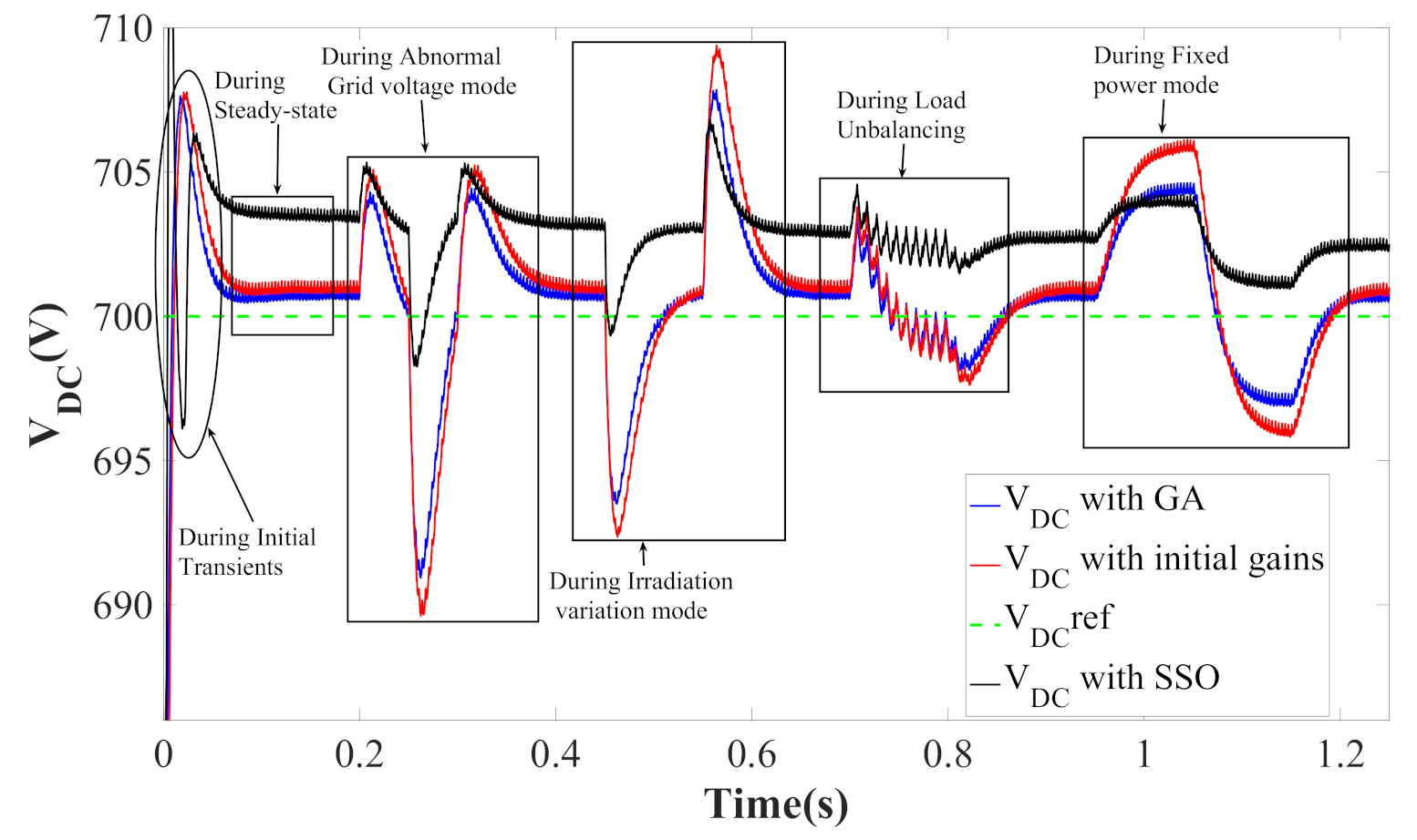
4.6. DC Bus Optimization Mode Performance

VDC is regulated by the PI controller, and its gains are optimized by GA and SSO algorithms. VDC variation is analyzed during the initial transients, abnormal grid voltage, irradiation variation, load unbalancing, and fixed power mode. The SSO-optimized VDC shows less fluctuations during initial transients and settles down more quickly in steady-state, compared to GA optimized and tuned with initial gains. VDC fluctuates more during abnormal grid voltage, irradiation variations, and fixed power mode. The SSO-optimized VDC shows significant improvement in terms of reduced fluctuations during all induced dynamic conditions and is kept near V DC ref = 700 V with minimum variations. Moreover, SSO-optimized VDC results in more accurate Id1, which is crucial for maintaining system stability and further improves the VSC control performance by precise extraction of fundamental current component. VDC is compared with the initial gains of the PI controller (i.e., kp = 1, ki = 0), GA-optimized gains (i.e., kp = 0.7388, ki = 0.0311), and SSO-optimized PI gains (i.e., kp = 2.5, ki = 0.8). The DC link voltage shows maximum changes during abnormal grid voltage conditions. VDC shows the minimum variation with the SSO-optimized gains of the PI controller during induced dynamic conditions, as shown in Figure 14.

4.7. Islanding and Re-Synchronization Mode Performance

The intentional islanding and re-synchronization of the grid to the rest of the system is simulated from 0.2 s to 0.4 s of simulation time. vSabc and iSabc reduce to zero during islanded operation. During grid-tied operation, iSabc follows its reference currents i S a b c * , and during isolated operation both will be insignificant. The system will operate satisfactorily in islanded mode only if the load voltage vLabc magnitude and frequency f are maintained. vLabc follows exactly its reference signal, i.e., v L a b c * , during isolated operation, as shown in Figure 15. The iCa reduces during islanded operation as power is only being supplied to the load, not to the grid, further confirmed by Pg. VT is also maintained around its reference value, i.e., 340, with slight variations during the isolated mode. The iSn becomes zero during islanded operation. iCn and iLn both compensate each other. Qg is also maintained at zero as the reactive power requirements are fulfilled by VSC only. On the DC side, the VPV, IPV, and PPV remain the same as steady-state and follow their respective reference signals. The IBAT and IUC become more negative, and IFC also reduces as Pg becomes zero during islanded operation; hence, the charging rate of the battery and UC increases with the increase in VBAT and VUC. The VDC is maintained around the 700 V level while following the reference signal during islanding and re-synchronization, as shown in Figure 16. The re-synchronization initiates at 0.4 s of simulation time. After matching the VT, f, and phase angle ω of the grid with load, the grid is re-synchronised with the system within three to four cycles, as shown in Figure 17.

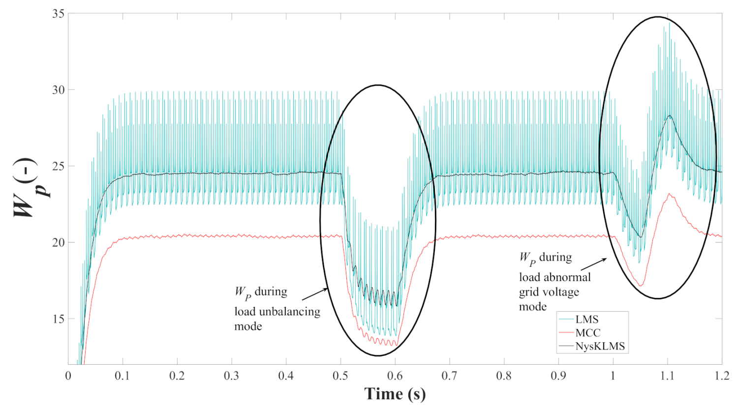
4.8. Comparison of VSC Controls

The W p with the proposed VSC control is compared with the LMS and MCC controls to show its relevancy and stability. The optimized DC bus produces precise Id1, which helps the NysMKLMS-based VSC control generate more accurate weights resulting in better extraction of fundamental current components. The VSC control performs better with accurate Id1, hence delivering enhanced power quality with reduced overall losses. The proposed control produces W p with fewer ripples compared to LMS- and MCC-based adaptive controls during steady-state, load unbalancing, and abnormal grid voltage conditions as shown in Figure 18. The proposed VSC control is more effective against Gaussian and non-Gaussian noises.

5. Conclusions

The paper demonstrates the three-phase four-wire grid-tied dual-stage PV-HESS system with the NysMKRSL algorithm based VSC control. The VSC displayed multifunctional operational capability such as reactive power compensation, load balancing, and power balancing while maintaining UPF during various induced dynamic conditions. The NysMKRSL-based VSC control delivers better performance, convergence rate, higher filtering accuracy, and less overall losses than other adaptive algorithms. The system displayed the capability of seamless transfer of control from grid islanding to grid re-synchronization without any major transients and instability in the proposed system. The energy storage elements of HESS complement each other in handling the system irregularities occurring on the grid side, load side, and the PV side. The DC link voltage is kept at the required level of 700 V during various dynamic conditions, and its deviation from the desired value is minimized by GA and SSO algorithms utilized for tuning the gains of the PI controller. The SSO algorithm’s adaptive nature delivers faster execution time, better accuracy of results, and reduces the chances of getting trapped at local minima even if the whole population deteriorates. The optimized DC-link generates precise loss component of current, which is crucial for maintaining stability and further improves the performance of NysMKRSL-based VSC control by generating more accurate weight signals and reducing overall losses of the system. The THD of the source and load, voltage, and current is found to be satisfactory as per IEEE519 standards.

Author Contributions

Conceptualization, M.C.; methodology, M.C.; software, I.K., I.H. and A.A.; formal analysis, I.K. and I.H.; research, I.K. and I.H.; writing—original draft preparation, I.K. and I.H.; writing—review and editing, I.H. and S.M.M.; supervising, I.H. and S.M.M. All authors have read and agreed to the published version of the manuscript.

Funding

This research received no external funding.

Acknowledgments

The authors would like to thank the editorial board as well as the anonymous reviewers for their valuable comments that have greatly increased the quality of this document.

Conflicts of Interest

The authors declare no conflict of interest. The funders had no role in the design of the study; in the collection, analyses, or interpretation of data; in the writing of the manuscript, or in the decision to publish the results.

Nomenclature

μ p x   x = a , b , c In-phase components
V d Voltage magnitude (V)
e n x   x = a , b , c Error signals
v S a b c Source voltage (V)
i S a b c Source current (A)
v L a b c Load voltage (V)
i L a b c Load current (A)
W P x   x = a , b , c Weight signals
β , σ Kernel function, kernel width
λ , μ Risk sensitive parameter, step size
W P V Feed-forward term
W P Average weight signals
W S P Overall weight
i S x * x = a , b , c Reference source current (A)
W S P f i x     W S P during fixed power mode
i S x f i x * x = a , b , c Fixed power mode reference currents (A)
f Frequency (Hz)
v a b c * Reference voltage (V)
v L a b c * Reference Load voltage (V)
ω s Grid voltage phase angle
ω L Load voltage phase angle
Δ ω Change in phase angle
i r e f R e S y n Reference Resynchronized current (A)
K p U C , K i U C , K p B a t , K i B a t UC and battery gains
I d 1 Loss component of current
V BAT Battery voltage (A)
I BAT Battery current (A)
I BAT * Reference battery current (A)
V UC UC voltage (V)
I UC UC current (A)
I UC * Reference UC current (A)
V DC DC bus voltage (V)
V DC ref Reference DC bus voltage (V)
x j 1 , x j i Position of leader & follower salp
F j Food position
u b j , l b j Upper and lower bound
c 1 , c 2 , c 3 Uniformly generated random no.
l   &   L Current and maximum iteration
vSa, iSaPhase ‘a’ grid voltage & current
vLa, iLaPhase ‘a’ load voltage & current
i S n Source neutral current (A)
i S n * Reference source neutral current (A)
i C n Compensator neutral current (A)
i L n Load neutral current (A)
V PV PV voltage (V)
V P V * Reference PV voltage (V)
I PV PV current (A)
I PV * Reference PV current (A)
P PV PV power (kW)
P PV * Reference PV power (kW)
P g Active power (kW)
P g * Reference active power (kW)
Q g Reactive power (kVAr)
Q g * Reference reactive power (kVAr)
N No. of search agents
tTotal iterations
NysMKRSLNyström minimum kernel risk-sensitive loss
VSCVoltage source converter
HESSHybrid energy storage system
UPFUnity power factor
PIProportional integral
SSOSalp swarm optimization
UCUltracapacitor
PEMFCProton Exchange Membrane FuelCell
PVPhotovoltaic
AIArtificial intelligence
CSCCurrent source converter
GAGenetic algorithm
PSOParticle swarm optimization
MKAFMulti kernel adaptive filter
InCIncremental conductance
PCCPoint of common coupling
InCIncremental conductance
VQVector Quantization
RFFRandom Fourier feature
GCCGrid current control
THDTotal harmonics distortion
HCCHysteresis current controller
MCSMaster control switch
ISE Integral square error

References

  1. IEA. Solar PV; IEA: Paris, France, 2020. Available online: https://www.iea.org/reports/solar-pv (accessed on 1 March 2021).
  2. IEA. World Energy Outlook 2020; IEA: Paris, France, 2020. Available online: https://www.iea.org/reports/world-energy-outlook-2020 (accessed on 1 March 2021).
  3. Stamford, L.; Azapagic, A. Environmental Impacts of Photovoltaics: The Effects of Technological Improvements and Transfer of Manufacturing from Europe to China. Energy Technol. 2018, 6, 1148–1160. [Google Scholar] [CrossRef]
  4. Vrînceanu, A.; Grigorescu, I.; Dumitraşcu, M.; Mocanu, I.; Dumitrica, C.; Micu, D.; Kucsicsa, G.; Mitrica, B. Impacts of photovoltaic farms on the environment in the Romanian plain. Energies 2019, 12, 2533. [Google Scholar] [CrossRef] [Green Version]
  5. Singh, B.; Chandra, A.; Al-haddad, K. Power Quality Problems and Mitigation Techniques; John Wiley & Sons: Hoboken, NJ, USA, 2015; ISBN 9781118922057. [Google Scholar]
  6. Agarwal, R.K.; Hussain, I.; Singh, B. Application of LMS-Based NN Structure for Power Quality Enhancement in a Distribution Network. IEEE Trans. Neural Netw. Learn. Syst. 2018, 29, 1598–1607. [Google Scholar] [CrossRef] [PubMed]
  7. Agarwal, R.K.; Hussain, I.; Singh, B. LMF-based control algorithm for single stage three-phase grid integrated solar PV system. IEEE Trans. Sustain. Energy 2016, 7, 1379–1387. [Google Scholar] [CrossRef]
  8. Kumar, N.; Hussain, I.; Singh, B. Normal Harmonic Search Algorithm-Based MPPT for Solar PV System and Integrated With Grid Using Reduced Sensor Approach and PNKLMS Algorithm. IEEE Trans. Ind. Appl. 2018, 54, 6343–6352. [Google Scholar] [CrossRef]
  9. Kumar, N.; Singh, B. ANOVA Kernel Kalman Filter for Multi-Objective Grid Integrated Solar Photovoltaic-Distribution Static Compensator. IEEE Trans. Circuits Syst. I Regul. Pap. 2019, 66, 4256–4264. [Google Scholar] [CrossRef]
  10. Kumar, N.; Singh, B.; Panigrahi, B.K.; Chakraborty, C.; Suryawanshi, H.M.; Verma, V. Integration of solar PV with low-voltage weak grid system: Using normalized laplacian kernel adaptive Kalman filter and learning based InC algorithm. IEEE Trans. Power Electron. 2019, 34, 10746–10758. [Google Scholar] [CrossRef]
  11. Modi, G.; Kumar, S.; Singh, B. A Maximum Correntropy Criteria Based Adaptive Algorithm for an Improved Power Quality SPV System. In Proceedings of the 8th Power India International Conference (PIICON), Kurukshetra, India, 10–12 December 2018; pp. 1–6. [Google Scholar] [CrossRef]
  12. Ranjan, A.; Kewat, S.; Singh, B. Reweighted Zero Attracting Maximum Correntropy Criterion Algorithm based Solar Grid Interfaced System for Alleviating Power Quality Problems. In Proceedings of the IEEE 9th Power India International Conference (PIICON), Sonepat, India, 28 February–1 March 2020; pp. 1–6. [Google Scholar] [CrossRef]
  13. Chankaya, M.; Hussain, I.; Ahmad, A. Variable parameter zero-attracting least mean square control of multifunctional PV-Battery-Fuel Cell Grid-tied system. Int. J. Power Energy Syst. 2021, 41. [Google Scholar] [CrossRef]
  14. Chen, B.; Xing, L.; Xu, B.; Zhao, H.; Zheng, N.; Príncipe, J.C. Kernel Risk-Sensitive Loss: Definition, Properties and Application to Robust Adaptive Filtering. IEEE Trans. Signal Process. 2017, 65, 2888–2901. [Google Scholar] [CrossRef] [Green Version]
  15. Zhang, T.; Wang, S.; Huang, X.; Wang, L. The Nyström minimum kernel risk-sensitive loss algorithm with k-means sampling. J. Frankl. Inst. 2020, 357, 10082–10099. [Google Scholar] [CrossRef]
  16. Panten, N.; Hoffmann, N.; Fuchs, F.W. Finite Control Set Model Predictive Current Control for Grid-Connected Voltage-Source Converters with LCL Filters: A Study Based on Different State Feedbacks. IEEE Trans. Power Electron. 2016, 31, 5189–5200. [Google Scholar] [CrossRef]
  17. Dragičević, T.; Novak, M. Weighting Factor Design in Model Predictive Control of Power Electronic Converters: An Artificial Neural Network Approach. IEEE Trans. Ind. Electron. 2019, 66, 8870–8880. [Google Scholar] [CrossRef] [Green Version]
  18. Patowary, M.; Panda, G.; Naidu, B.R.; Deka, B.C. ANN-based adaptive current controller for on grid DG system to meet frequency deviation and transient load challenges with hardware implementation. IET Renew. Power Gener. 2018, 12, 61–71. [Google Scholar] [CrossRef]
  19. Saroha, J.; Singh, M.; Jain, D.K. ANFIS-Based add-on controller for unbalance voltage compensation in a low-voltage microgrid. IEEE Trans. Ind. Informatics 2018, 14, 5338–5345. [Google Scholar] [CrossRef]
  20. Saxena, N.; Singh, B.; Vyas, A.L. Single-phase solar PV system with battery and exchange of power in grid-connected and standalone modes. IET Renew. Power Gener. 2017, 11, 325–333. [Google Scholar] [CrossRef]
  21. Beniwal, N.; Hussain, I.; Singh, B. Control and operation of a solar PV-battery-grid-tied system in fixed and variable power mode. IET Gener. Transm. Distrib. 2018, 12, 2633–2641. [Google Scholar] [CrossRef]
  22. Ku Ahmad, K.N.E.; Selvaraj, J.; Rahim, N.A. A review of the islanding detection methods in grid-connected PV inverters. Renew. Sustain. Energy Rev. 2013, 21, 756–766. [Google Scholar] [CrossRef]
  23. Kim, M.S.; Haider, R.; Cho, G.J.; Kim, C.H.; Won, C.Y.; Chai, J.S. Comprehensive review of islanding detection methods for distributed generation systems. Energies 2019, 12, 1. [Google Scholar] [CrossRef] [Green Version]
  24. Trujillo Rodriguez, C.; Velasco De La Fuente, D.; Garcera, G.; Figueres, E.; Guacaneme Moreno, J.A. Reconfigurable control scheme for a PV microinverter working in both grid-connected and Island modes. IEEE Trans. Ind. Electron. 2013, 60, 1582–1595. [Google Scholar] [CrossRef]
  25. Kim, H.; Yu, T.; Choi, S. Indirect current control algorithm for utility interactive inverters in distributed generation systems. IEEE Trans. Power Electron. 2008, 23, 1342–1347. [Google Scholar] [CrossRef]
  26. Mahmood, H.; Jiang, J. A Control Strategy of a Distributed Generation Unit for Seamless Transfer between Grid Connected and Islanded Modes. In Proceedings of the 2014 IEEE 23rd International Symposium on Industrial Electronics (ISIE), Istanbul, Turkey, 1–4 June 2014; pp. 2518–2523. [Google Scholar] [CrossRef]
  27. Micallef, A.; Member, S.; Apap, M.; Spiteri-staines, C.; Guerrero, J.M. Single-Phase Microgrid With Seamless Transition Capabilities between Modes of Operation. IEEE Tran. Smart Grid 2015, 6, 2736–2745. [Google Scholar] [CrossRef] [Green Version]
  28. Lim, K.; Choi, J. Seamless grid synchronization of a proportional+resonant control-based voltage controller considering non-linear loads under Islanded mode. Energies 2017, 10, 1514. [Google Scholar] [CrossRef] [Green Version]
  29. Fatu, M.; Blaabjerg, F.; Boldea, I. Grid to Standalone Transition Motion-Sensorless Dual-Inverter Control of PMSG With Asymmetrical Grid Voltage Sags and Harmonics Filtering. IEEE Trans. Power Electron. 2014, 29, 3463–3472. [Google Scholar] [CrossRef]
  30. Modes, S.; Yao, Z.; Xiao, L.; Yan, Y. Seamless Transfer of Single-Phase Grid-Interactive Inverters between Grid-Connected. IEEE Trans. Power Electron. 2010, 25, 1597–1603. [Google Scholar] [CrossRef]
  31. Sharaf, A.M.; El-Gammal, A.A.A. A novel PSO-based hybrid PV-FC-diesel-battery electric PID-controller drive system for electric vehicle traction. In Proceedings of the 2010 IEEE Electrical Power & Energy Conference, Halifax, NS, Canada, 25–27 August 2010. [Google Scholar] [CrossRef]
  32. Sharma, R.; Kewat, S.; Singh, B. Robust MMSOGI-FLL control algorithm for power quality improvement of solar PV-SyRG pico hydro-BES based islanded microgrid with dynamic load. IET Power Electron. 2020, 13, 2874–2884. [Google Scholar] [CrossRef]
  33. Ise, T.; Kita, M.; Taguchi, A. A hybrid energy storage with a SMES and secondary battery. IEEE Trans. Appl. Supercond. 2005, 15, 1915–1918. [Google Scholar] [CrossRef]
  34. Natarajan, S.K.; Kamran, F.; Ragavan, N.; Rajesh, R.; Jena, R.K.; Suraparaju, S.K. Analysis of PEM hydrogen fuel cell and solar PV cell hybrid model. Mater. Today Proc. 2019, 17, 246–253. [Google Scholar] [CrossRef]
  35. Karami, N.; Moubayed, N.; Outbib, R. Energy management for a PEMFC-PV hybrid system. Energy Convers. Manag. 2014, 82, 154–168. [Google Scholar] [CrossRef]
  36. Nengroo, S.H.; Kamran, M.A.; Ali, M.U.; Kim, D.H.; Kim, M.S.; Hussain, A.; Kim, H.J. Dual battery storage system: An optimized strategy for the utilization of renewable photovoltaic energy in the United Kingdom. Electronics 2018, 7, 177. [Google Scholar] [CrossRef] [Green Version]
  37. Zhang, Q.; Mao, M.; Ke, G.; Zhou, L.; Xie, B. Stability problems of PV inverter in weak grid: A review. IET Power Electron. 2020, 13, 2165–2174. [Google Scholar] [CrossRef]
  38. Abedi, A.; Rezaie, B.; Khosravi, A.; Shahabi, M. DC-bus Voltage Control based on Direct Lyapunov Method for a Converter-based Stand-alone DC Micro-grid. Electr. Power Syst. Res. 2020, 187, 106451. [Google Scholar] [CrossRef]
  39. Hassoune, A.; Khafallah, M.; Mesbahi, A.; Bouragba, T. Optimization Techniques for DC Bus Voltage Balancing in a PV Grid System Based EVs Charging Station. Adv. Sci. Technol. Innov. 2019, 123–131. [Google Scholar] [CrossRef]
  40. Elvira, D.G.; Blaví, H.V.; Pastor, À.C.; Salamero, L.M. Efficiency optimization of a variable bus voltage DC microgrid. Energies 2018, 11, 3090. [Google Scholar] [CrossRef] [Green Version]
  41. Zhou, X.; Zhou, Y.; Ma, Y.; Yang, L.; Yang, X.; Zhang, B. DC bus voltage control of grid-side converter in permanent magnet synchronous generator based on improved second-order linear active disturbance rejection control. Energies 2020, 13, 4592. [Google Scholar] [CrossRef]
  42. Song, L.; Huang, L.; Long, B.; Li, F. A genetic-algorithm-based DC current minimization scheme for transformless grid-connected photovoltaic inverters. Energies 2020, 13, 746. [Google Scholar] [CrossRef] [Green Version]
  43. Gomes, A.D.O.; Gouvêa, M.M. DC power flow optimization with a parallel evolutionary algorithm. In Proceedings of the Sixth IEEE/PES Transmission and Distribution: Latin America Conference and Exposition (T&D-LA), Montevideo, Uruguay, 3–5 September 2012; pp. 1–6. [Google Scholar] [CrossRef]
  44. Thameur, A.; Noureddine, B.; Abdelhalim, B.; Boualam, B.; Abdelkader, L.; Karima, B.; Tarak, B. Particle Swarm Optimization of PI Controllers in Grid-Connected PV Conversion Cascade Based Three Levels NPC Inverter. In Proceedings of the IEEE International Conference on Environment and Electrical Engineering and 2020 IEEE Industrial and Commercial Power Systems Europe (EEEIC/I&CPS Europe), Madrid, Spain, 9–12 June 2020. [Google Scholar] [CrossRef]
  45. Singh, A.; Sharma, V. Salp swarm algorithm-based model predictive controller for frequency regulation of solar integrated power system. Neural Comput. Appl. 2019, 31, 8859–8870. [Google Scholar] [CrossRef]
  46. Srikanth Goud, B.; Rao, B.L.; Devi, B.N.; Kumar, K.S.; Keerthi, N. Review on optimization techniques employed in distribution generation. J. Crit. Rev. 2020, 7, 639–645. [Google Scholar] [CrossRef]
Figure 1. Block diagram of the proposed system.
Energies 14 01365 g001
Figure 2. (a) Research methodology. (b) Voltage source converter (VSC) control based on the NysMKRSL algorithm.
Energies 14 01365 g002aEnergies 14 01365 g002b
Figure 3. Bi-directional buck-boost converter control.
Energies 14 01365 g003
Figure 4. Harmonic content of (a) v S a , (b) i S a , (c) v S a , and (d) i L a during steady-state.
Energies 14 01365 g004aEnergies 14 01365 g004b
Figure 5. Bode plot analysis of DC bus during steady-state.
Energies 14 01365 g005
Figure 6. Dynamic performance during insolation variation of v s a b c ,   i s a b c ,   i C a , V d ,   i L a , i S n , i C n ,   i L n ,   P g , and Q g .
Energies 14 01365 g006
Figure 7. Dynamic performance during insolation variation of V PV ,   I PV ,   P PV , V FC ,   I FC   , V Bat ,   I Bat ,   V UC ,   I UC ,   and   V DC .
Energies 14 01365 g007
Figure 8. Dynamic performance during load unbalancing of   v s a b c ,   i s a b c ,   i C a , V d ,   i L a , i S n , i C n ,   i L n ,   P g , and Q g .
Energies 14 01365 g008
Figure 9. Dynamic performance during load unbalancing V PV ,   I PV ,   P PV , V FC ,   I FC , V Bat ,   I Bat ,   V UC ,   I UC ,   and   V DC .
Energies 14 01365 g009
Figure 10. Dynamic performance during fixed power mode of   v s a b c ,   i s a b c ,   i C a , V d ,   i L a , i S n , i C n ,   i L n ,   P g , and Q g .
Energies 14 01365 g010
Figure 11. Dynamic performance during a fixed power mode of V PV ,   I PV ,   P PV , V FC ,   I FC , V Bat ,   I Bat ,   V UC ,   I UC ,   and   V DC .
Energies 14 01365 g011
Figure 12. Dynamic performance during abnormal grid mode of   v s a b c ,   i s a b c ,   i C a , V d ,   i L a , i S n , i C n ,   i L n ,   P g , and Q g .
Energies 14 01365 g012
Figure 13. Dynamic performance during abnormal grid voltage mode of V PV ,   I PV ,   P PV , V FC ,   I FC ,   V Bat ,   I Bat , V UC ,   I UC ,   and   V DC .
Energies 14 01365 g013
Figure 14. DC link voltage variations during various induced dynamic conditions.
Energies 14 01365 g014
Figure 15. Dynamic performance during islanding and re-synchronization of v S a b c ,   i S a b c , v L a b c   i L a ,   i C a ,   V d ,   i S n ,   i C n , i L n ,   P g , and Q g .
Energies 14 01365 g015
Figure 16. Dynamic performance during islanding and re-synchronization of V PV ,   I PV ,   P PV , V FC ,   I FC , V Bat ,   I Bat ,   V UC ,   I UC ,   and   V DC .
Energies 14 01365 g016
Figure 17. Comparison of Δ ω of v S a b c and v L a b c during grid islanding and re-synchronization.
Energies 14 01365 g017
Figure 18. Comparison of W p of LMS, MCC, and NysMKRSL algorithms.
Energies 14 01365 g018
Publisher’s Note: MDPI stays neutral with regard to jurisdictional claims in published maps and institutional affiliations.

