
Dynamic Performance Enhancement of Power Grids by Operating Solar Photovoltaic (PV) System as Supercapacitor Energy Storage


Abstract
:1. Introduction
- (i)
- The proposed PV system not only works in its typical mode of operation but also can improve the system stability whenever needed (i.e., whenever there are any disturbances in the grid). This is the additional advantage that can be achieved from the same PV system by momentarily connecting a supercapacitor at the PV panel terminal.
- (ii)
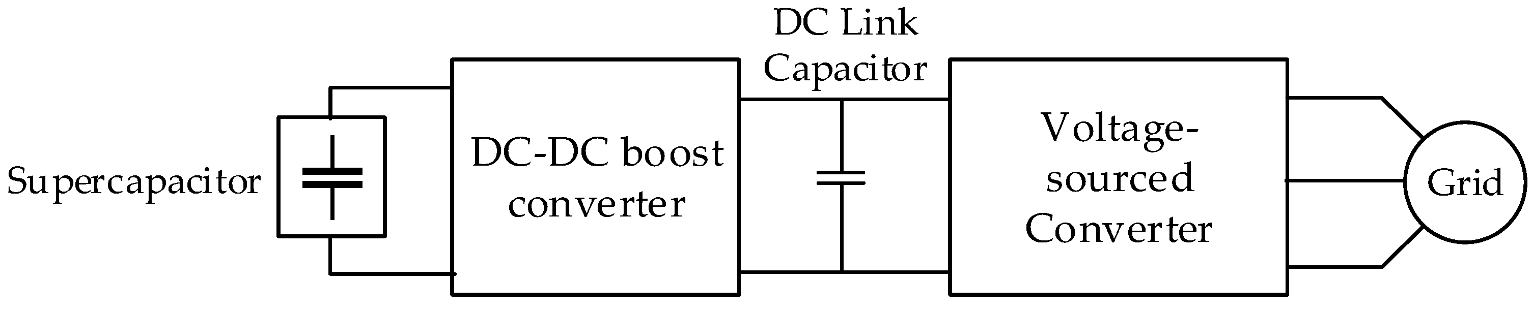
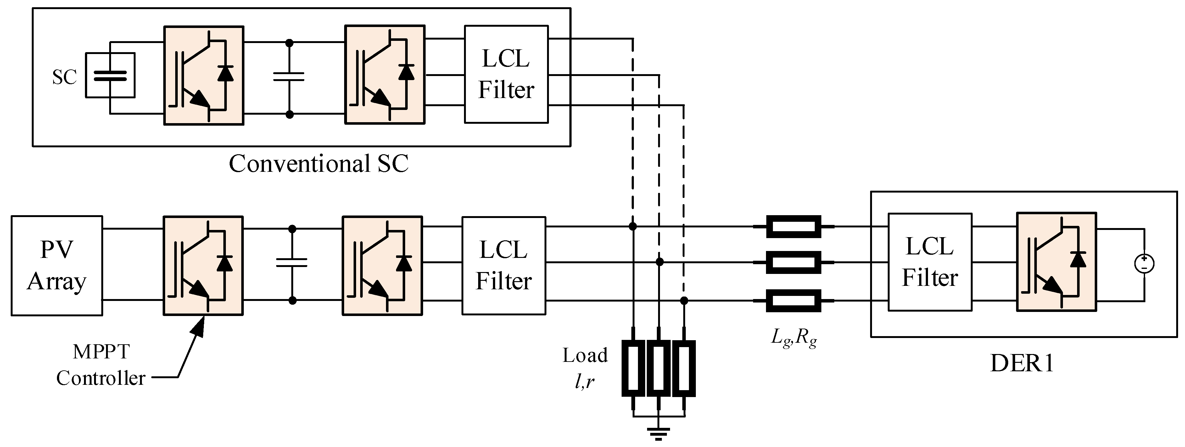
- To handle any disturbances (fault, load change, etc.) at the grid side, typically an auxiliary control device such as STATCOM, static var compensator (SVC), fault current limiter, or an extra energy storage device (such as a full supercapacitor energy storage unit, as shown in Figure 2, or a full battery energy storage system) is connected at the grid point, and the system stability is maintained. However, as per the proposed approach, because the same PV system will be used, it saves the cost of adding any auxiliary control devices at the grid point; that is, this technology will achieve significant cost savings due to the use of the existing PV system components as the SES unit.
2. Proposed PV-SES System Modeling
2.1. Principle of Operation
- (i)
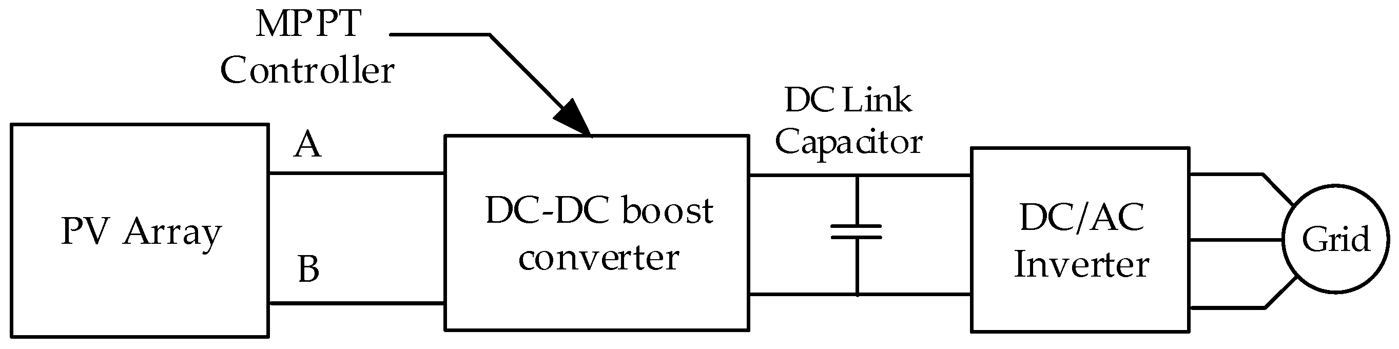
- PV system mode: In this mode, the proposed PV system will provide power to the grid, as usual, assuming there is sufficient solar irradiance (sunlight).
- (ii)
- Energy storage mode: In this mode, once there are any grid disturbances, such as faults or load changes, (irrespective of daytime, nighttime, cloudy situations), the same PV system changes to the energy storage (supercapacitor) mode through the switches, and by controlling active and reactive powers it improves the transient stability, fault-ride through capability, voltage sag, etc., of the grid. Once the grid stability is maintained, it changes back to the usual PV system mode above.
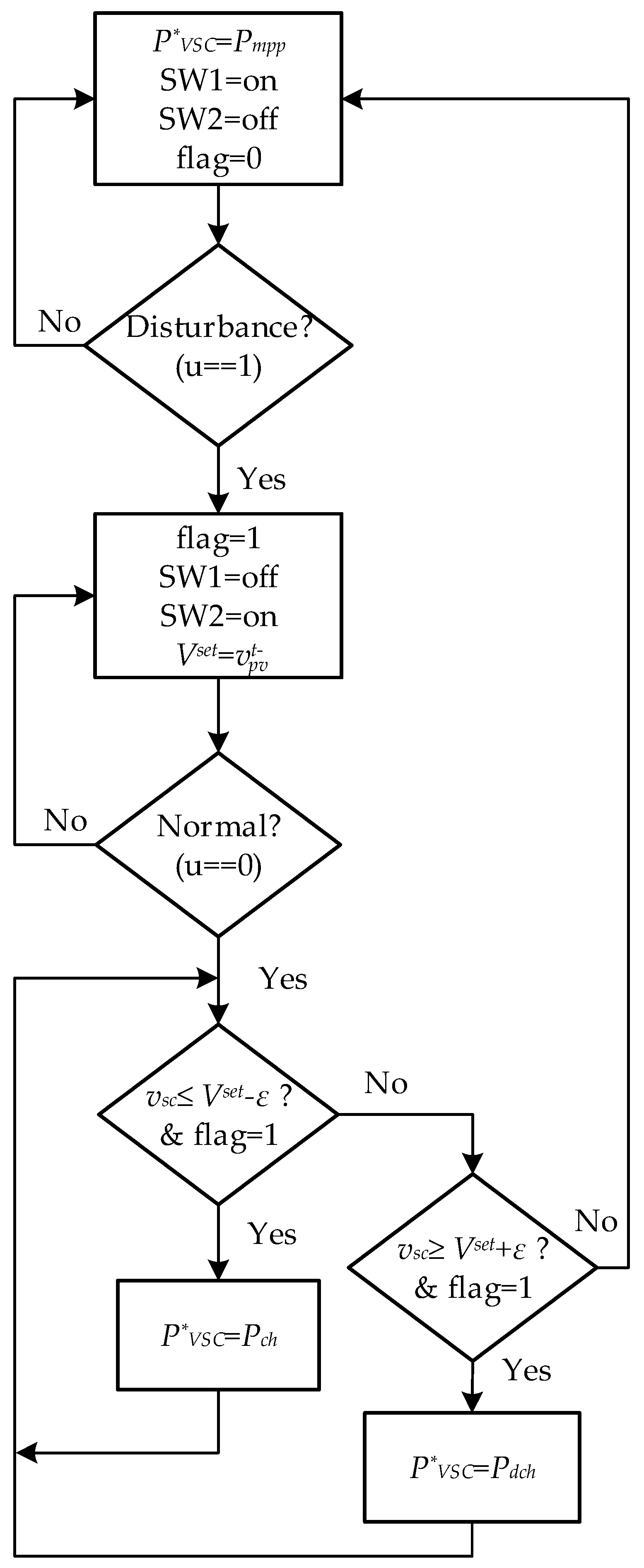
2.2. Control Algorithm
3. Components Models and Control Systems
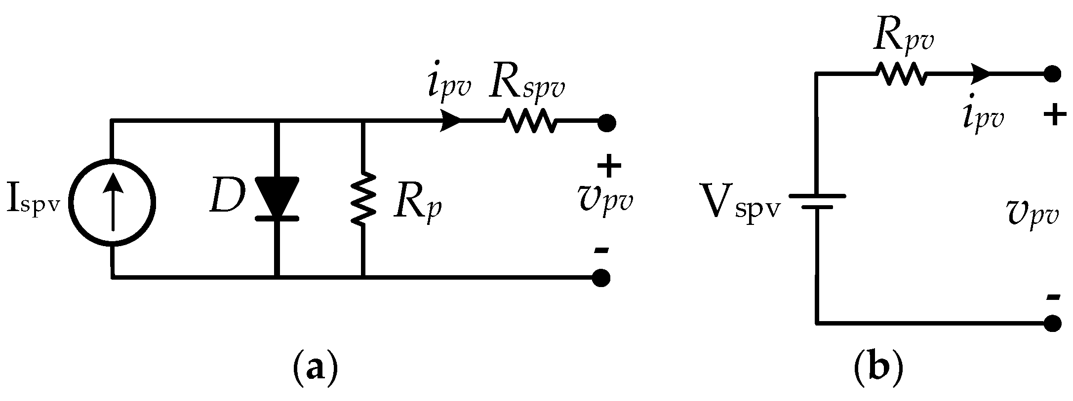
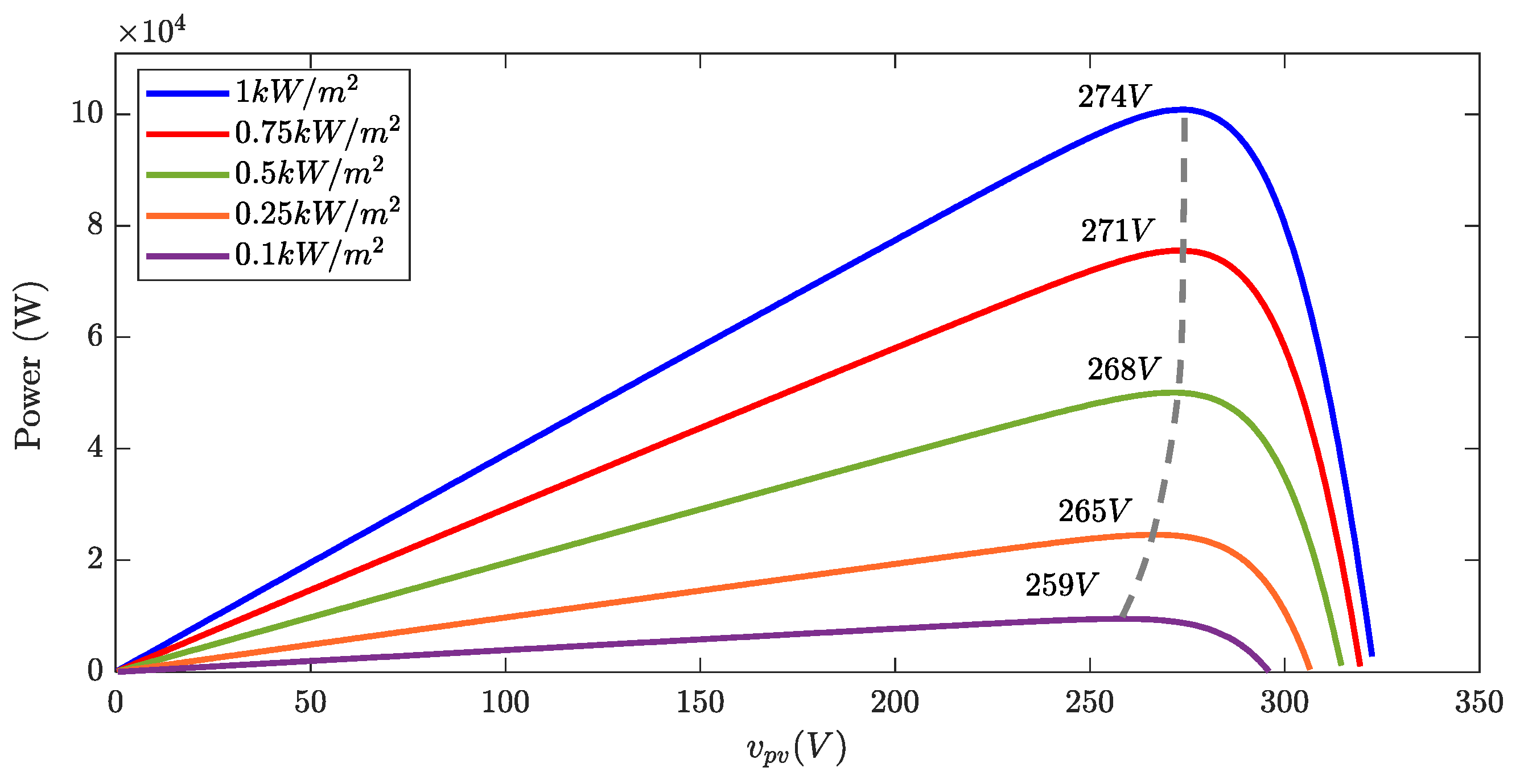
3.1. PV
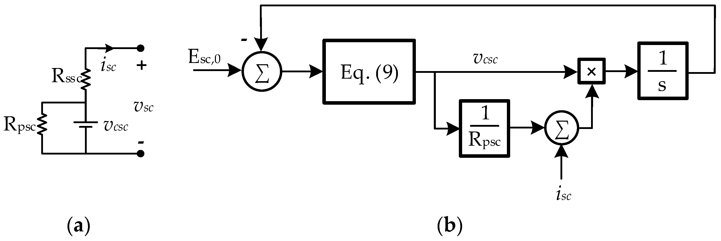
3.2. SC
3.3. Bidirectional DC-DC Converter
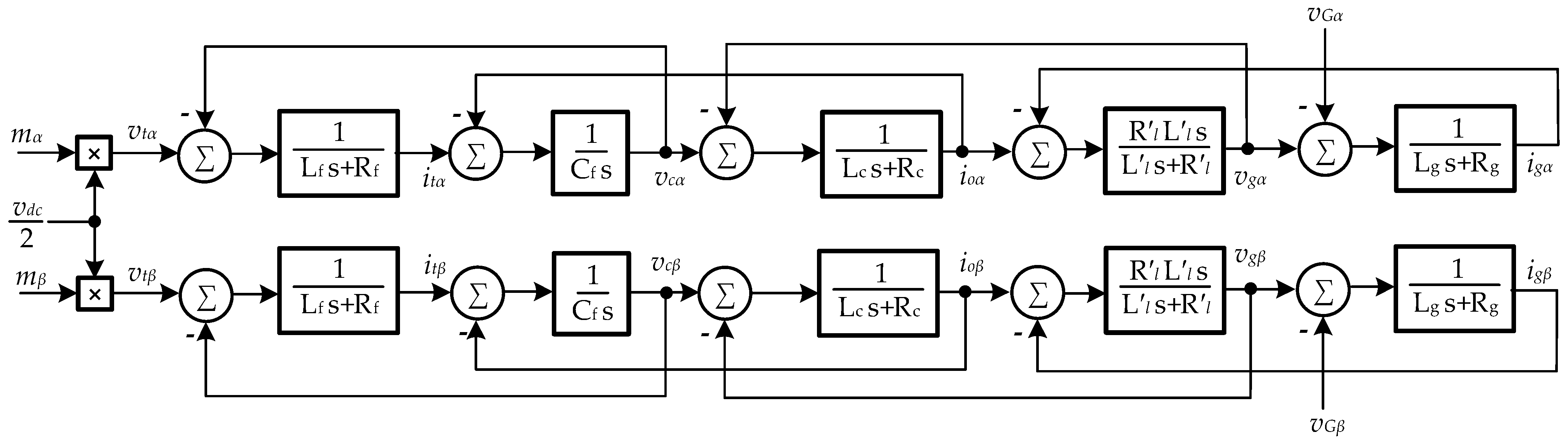
3.4. VSC, Load, and Transmission Line
4. Control Systems
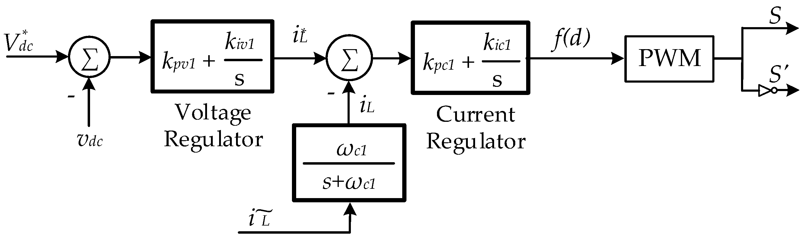
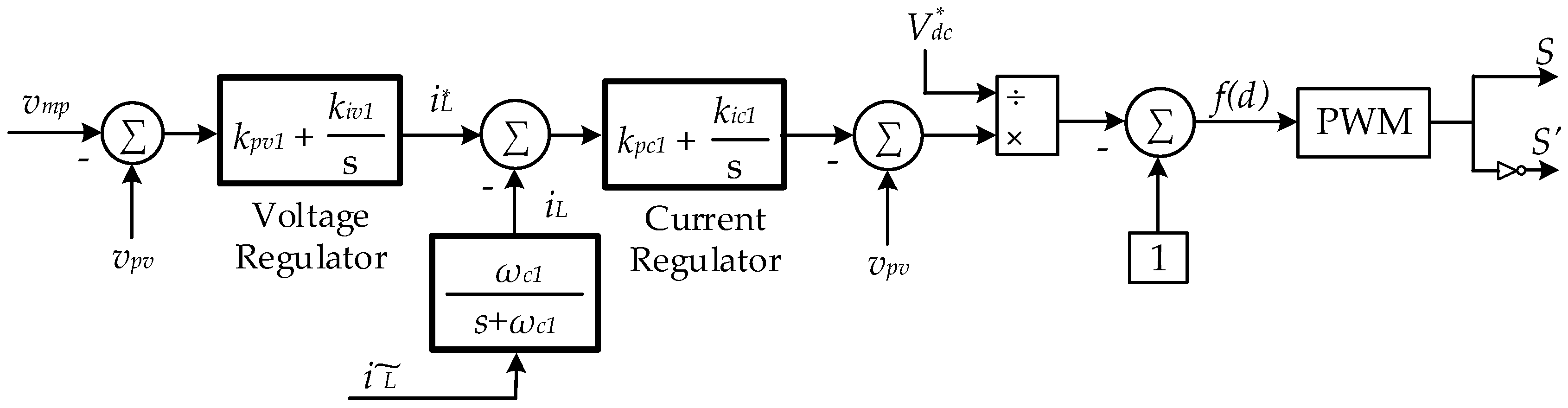
4.1. BDC Control
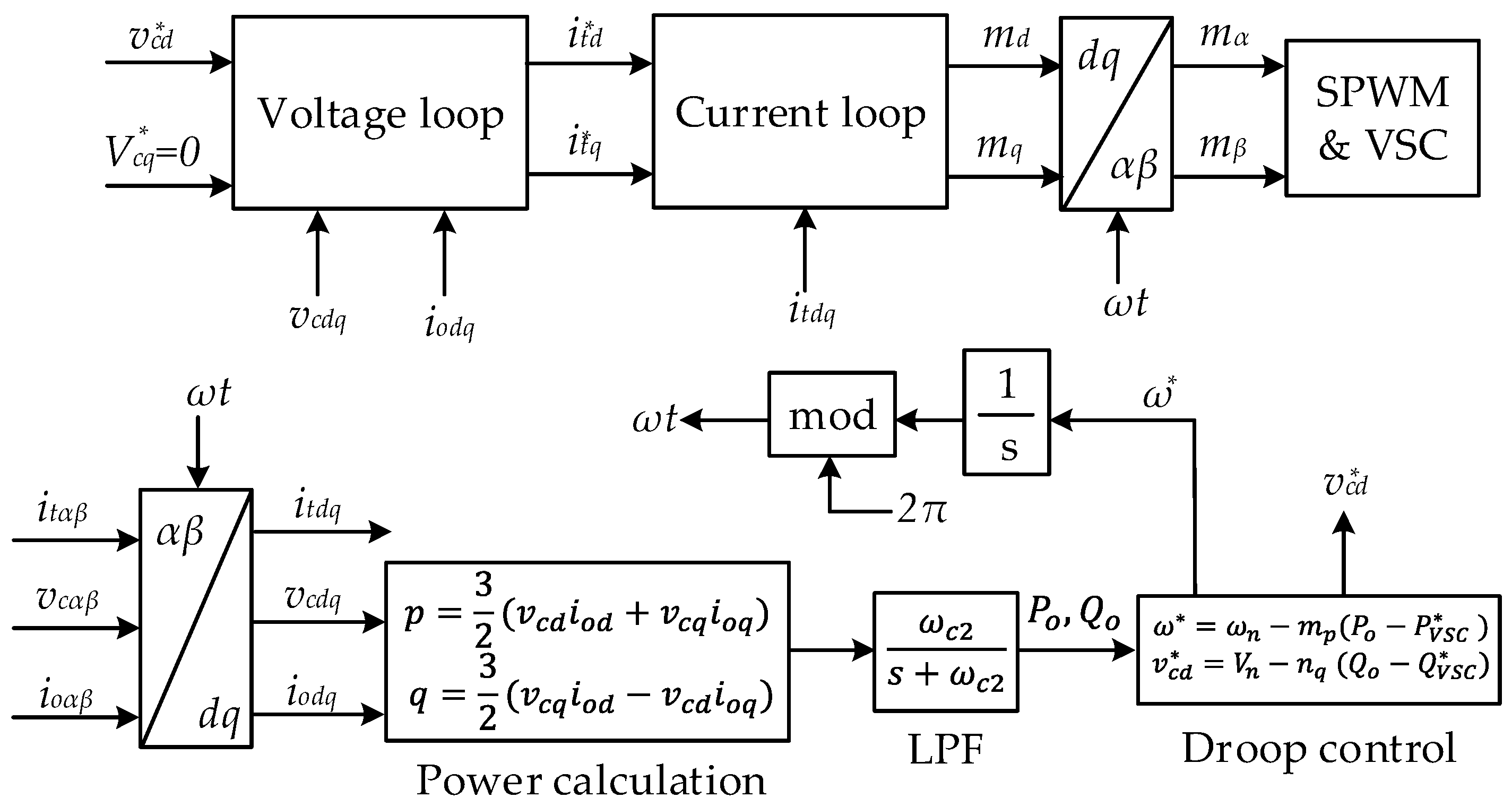
4.2. VSC Control
5. Nonlinear Mathematical Model and Small-Signal Stability Analyses
5.1. NMM
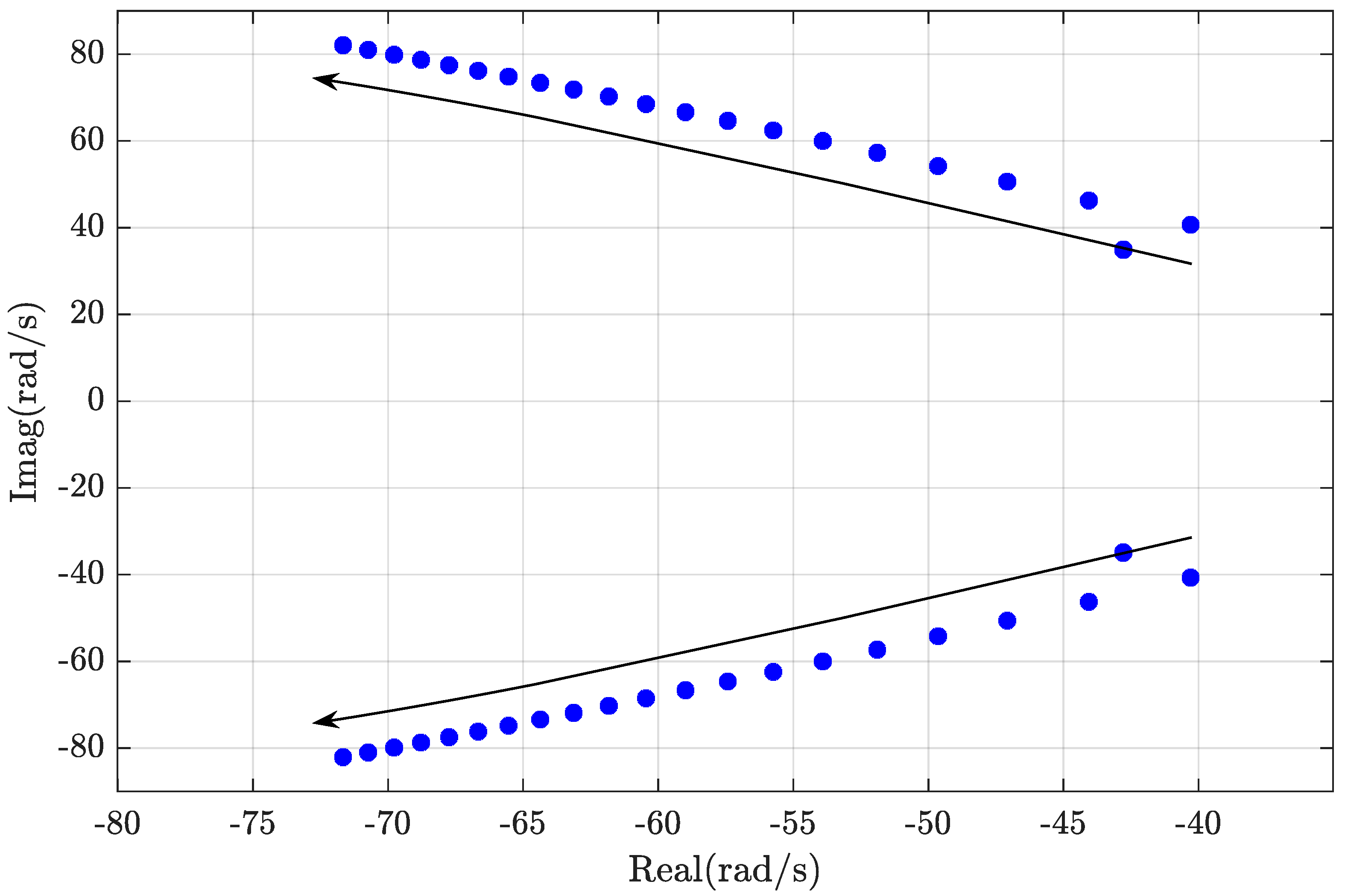
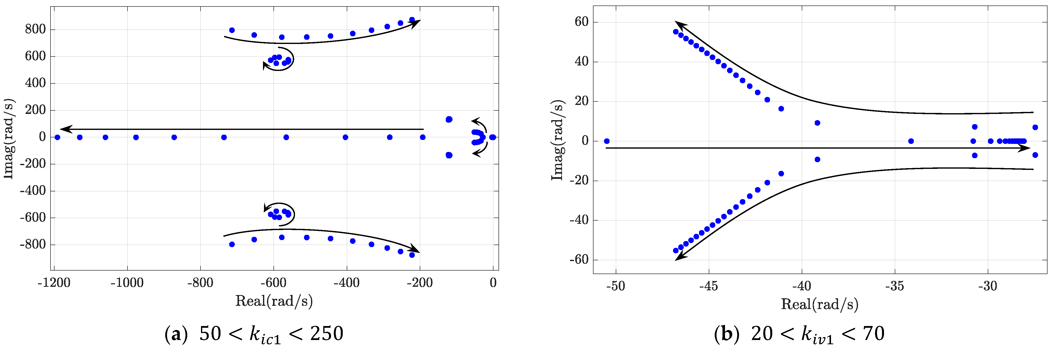
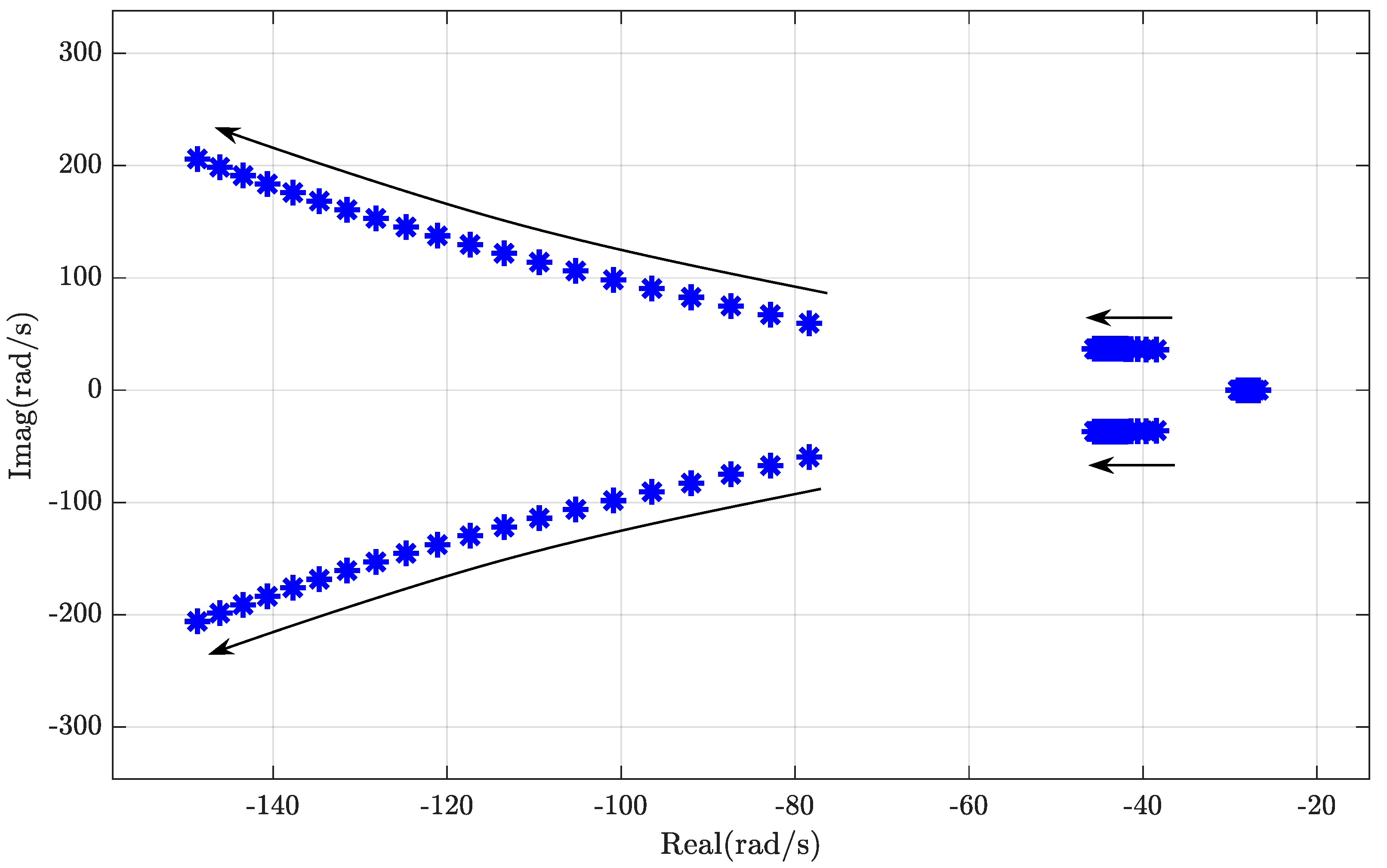
5.2. Small-Signal Analyses
6. Simulation Results and Discussions
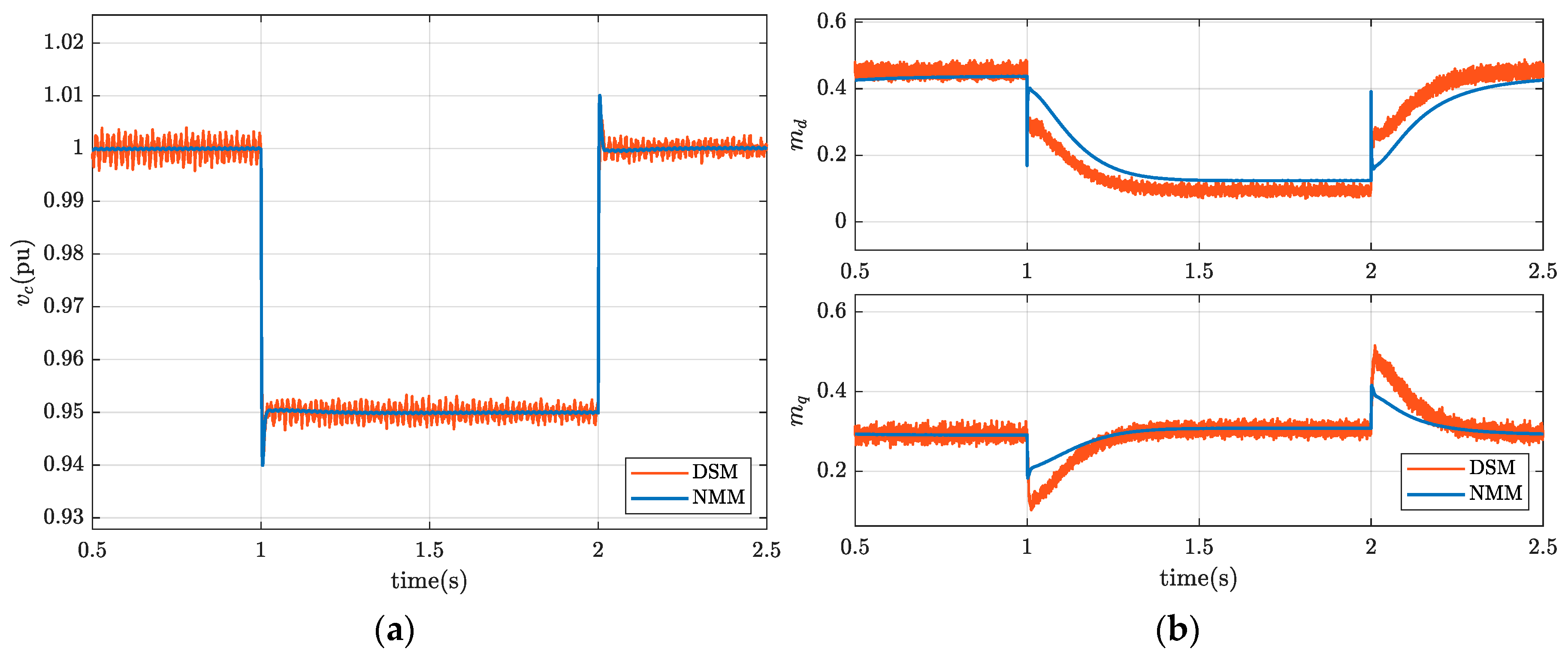
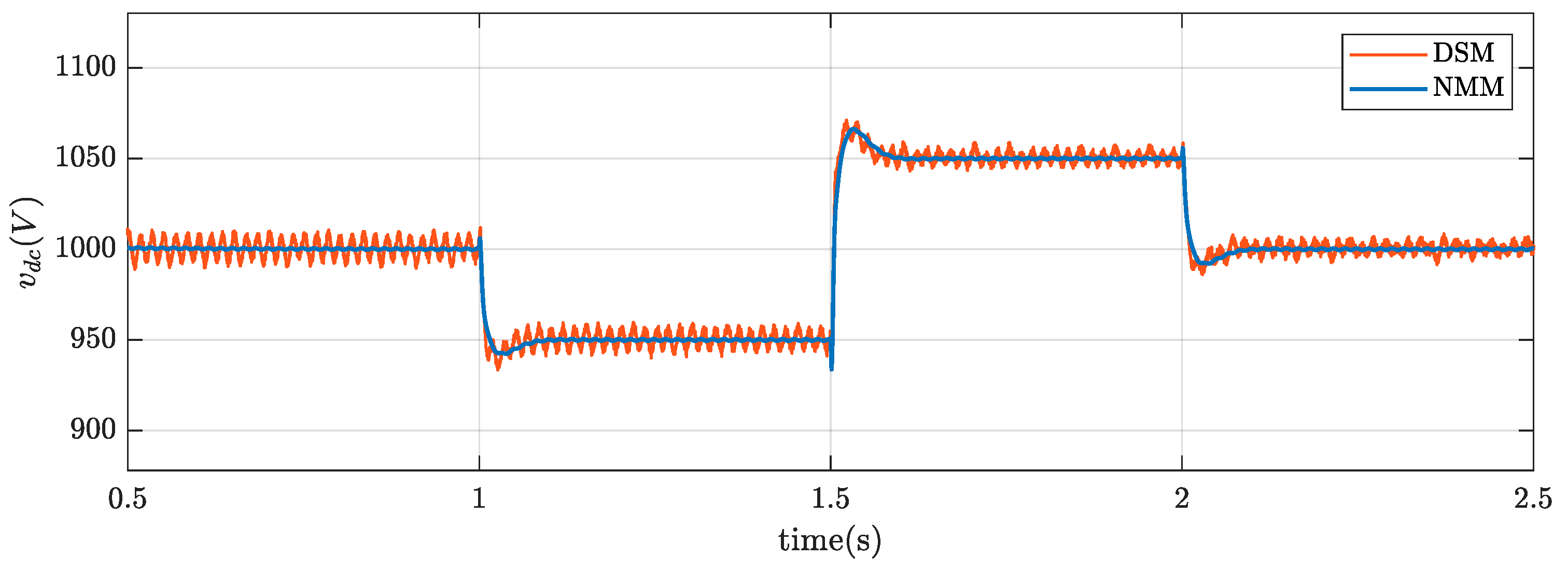
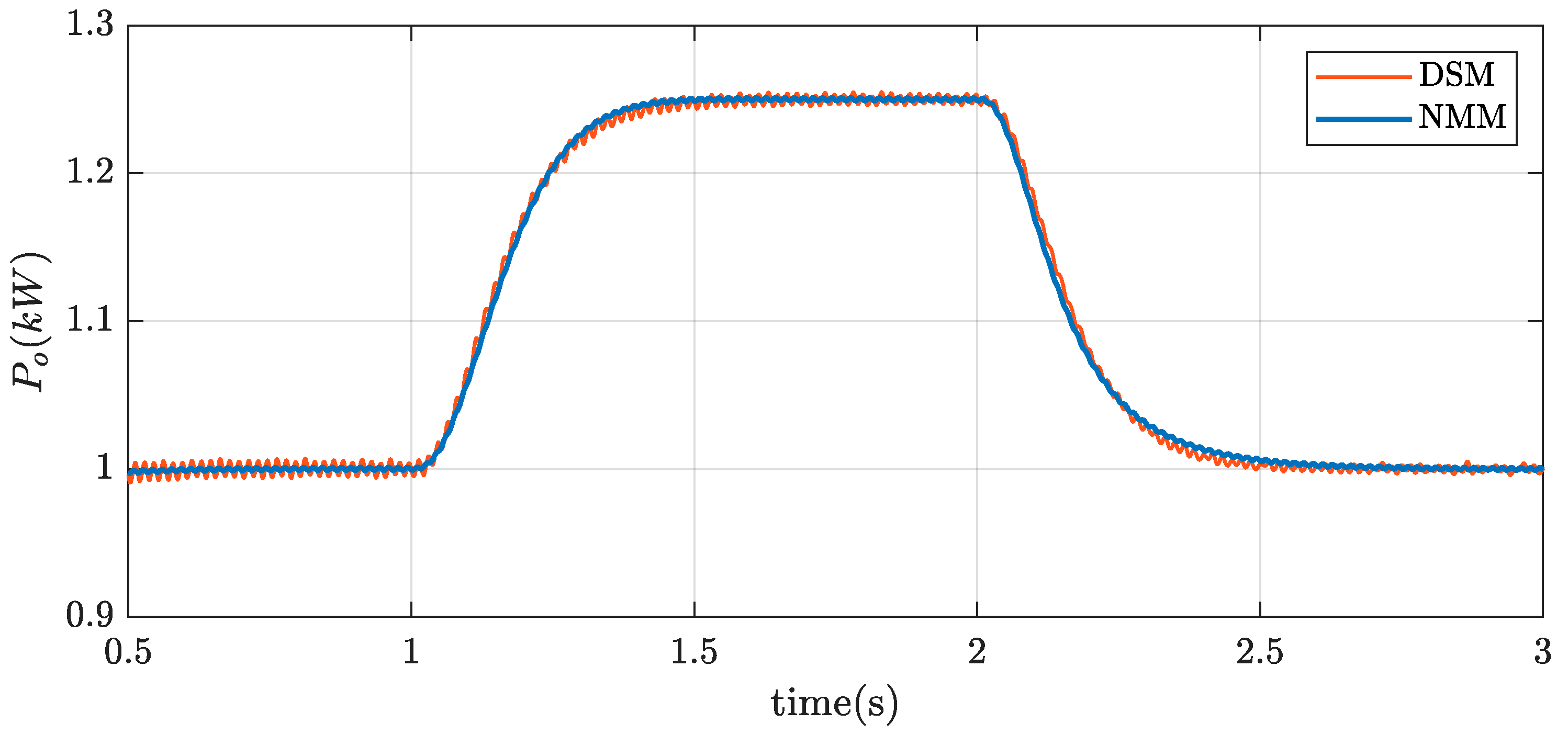
6.1. Validation of Dynamic Accuracy of NMM
6.1.1. Examining NMM Conformity
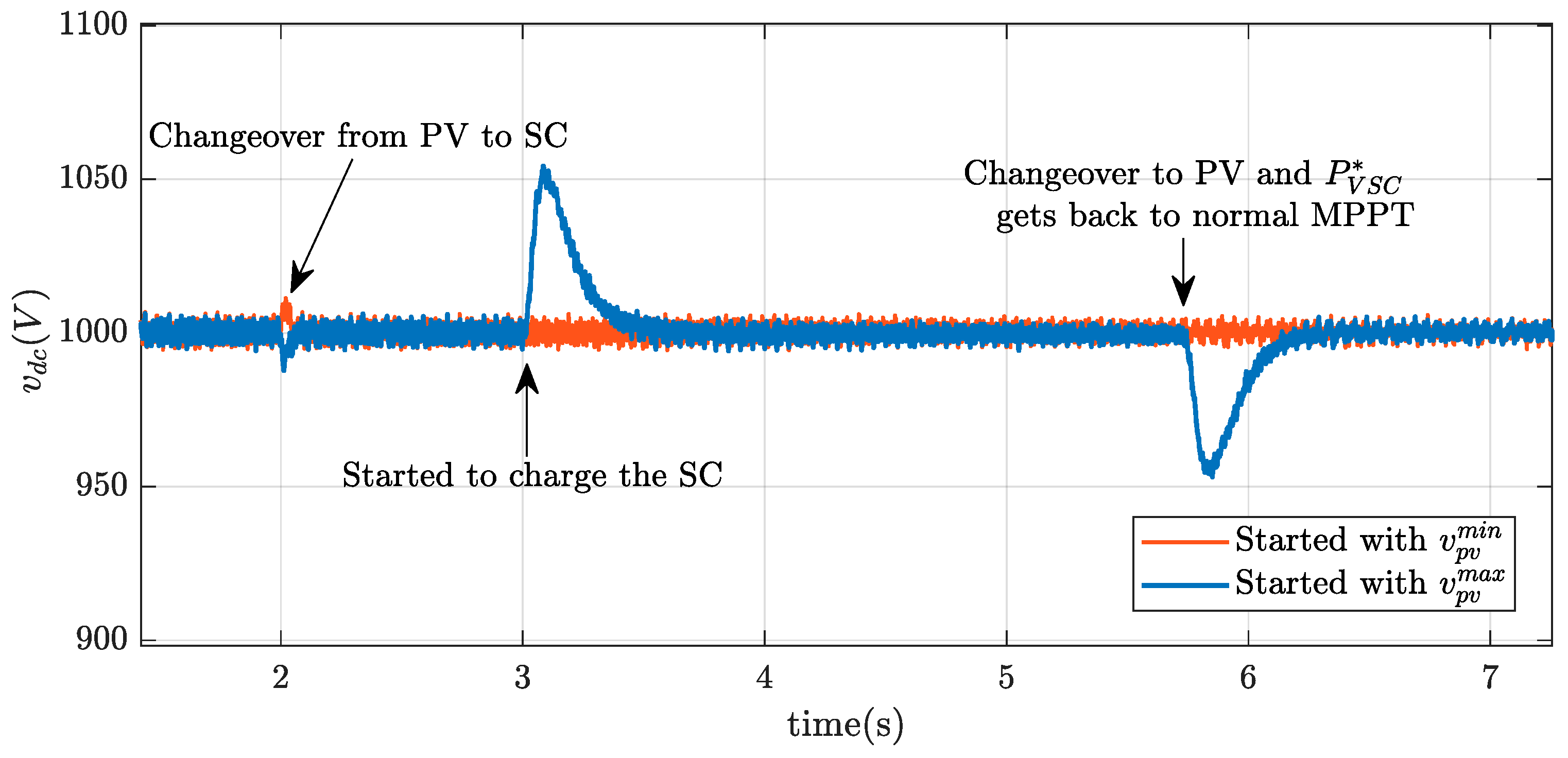
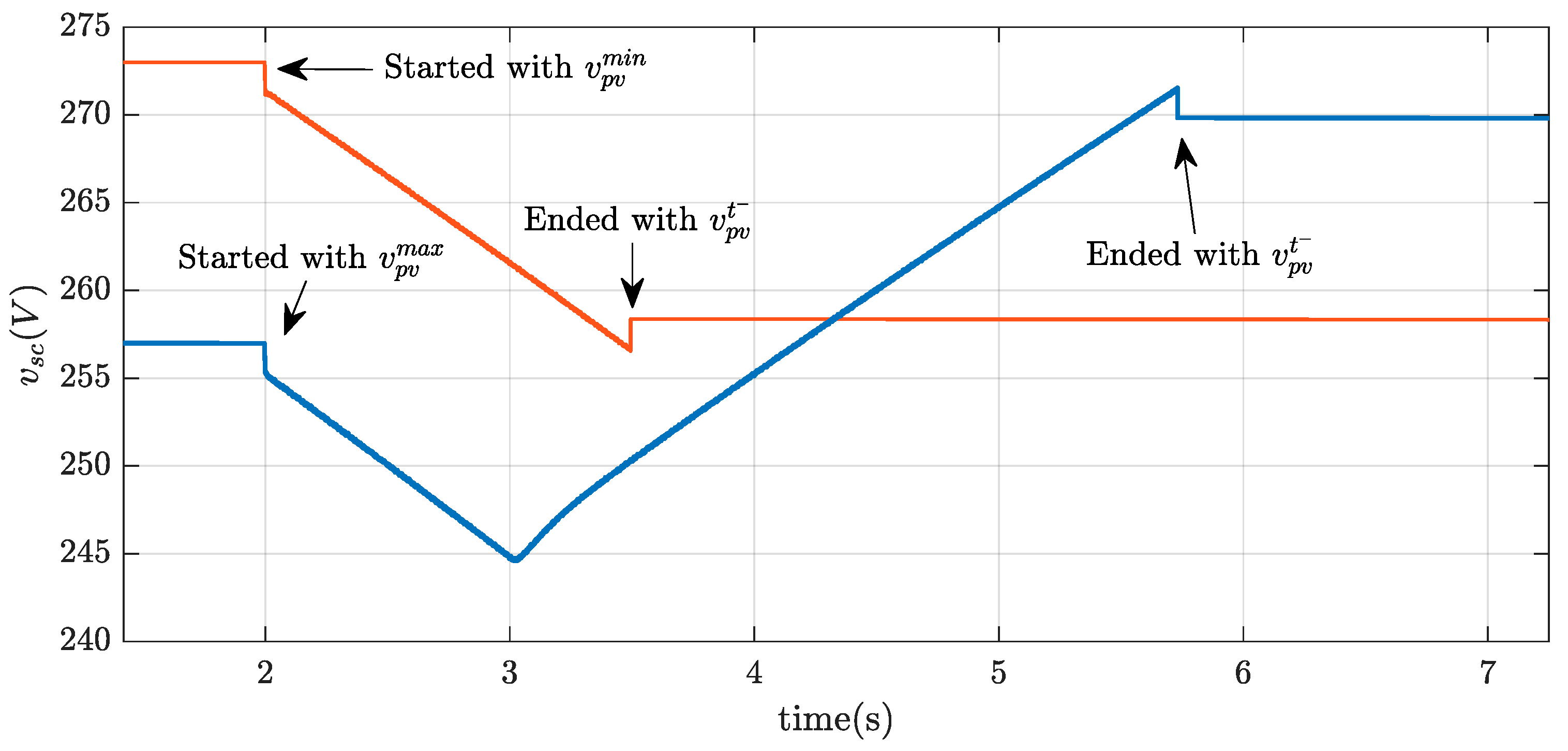
6.1.2. Changeover between PV and SC
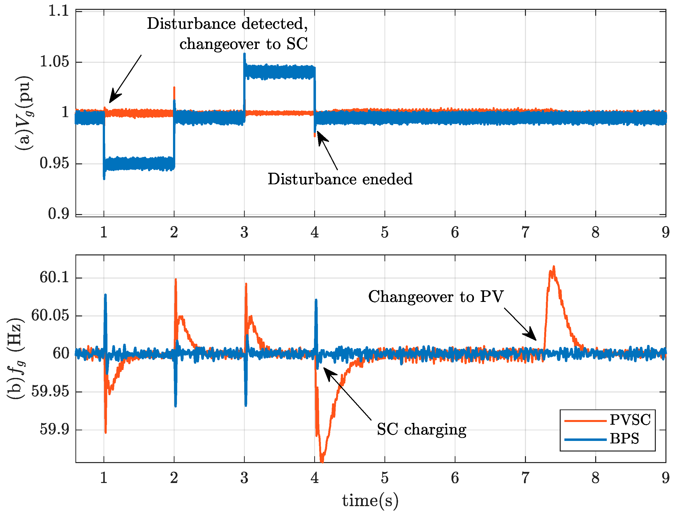
6.2. Effectiveness of Proposed PVSC System to Maintain Voltage Stability
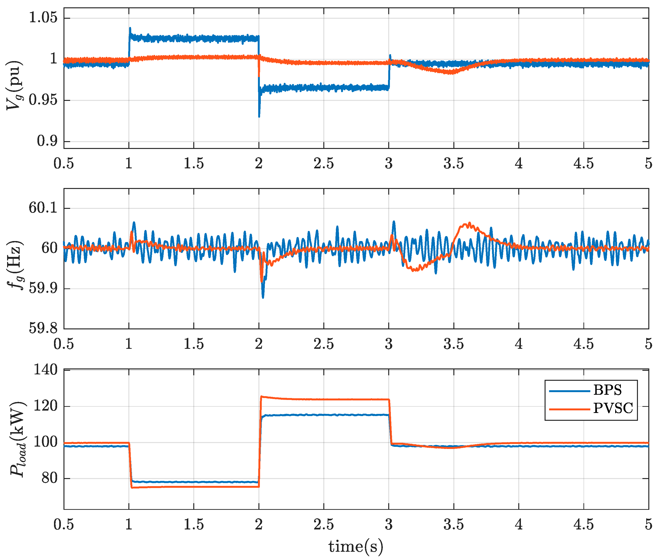
6.3. Stepwise Load Variation and Weak Connection to Grid
6.4. Performance Comparison between the Proposed PVSC and Conventional SC
6.4.1. Step Change in Local Load
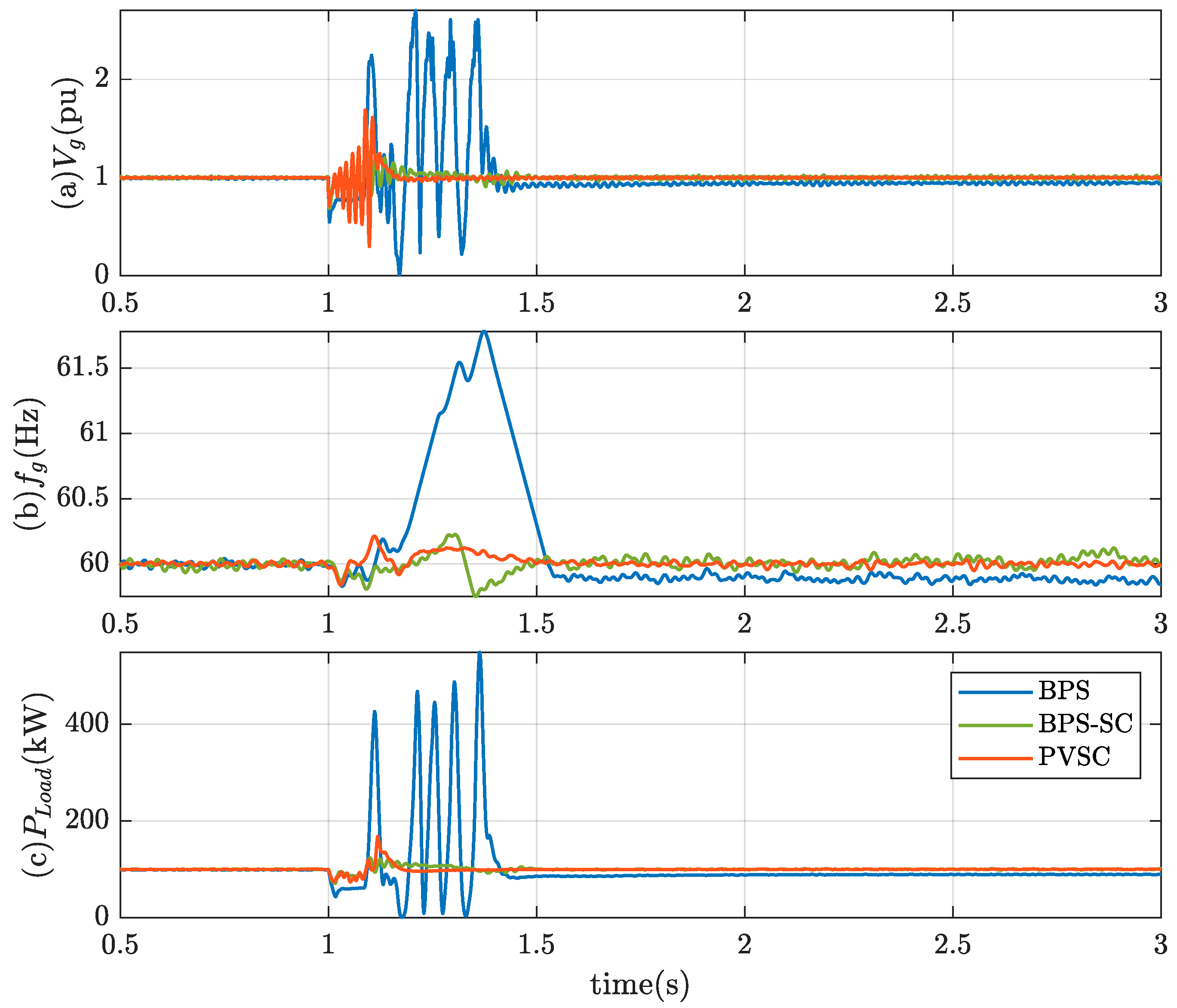
6.4.2. Fault Analysis
6.5. Cost-Effectiveness of the Proposed Approach
7. Conclusions
Author Contributions
Funding
Institutional Review Board Statement
Informed Consent Statement
Data Availability Statement
Conflicts of Interest
References
- Kumar, A.; Verma, V. Performance Enhancement of Single-Phase Grid-Connected PV System under Partial Shading Using Cascaded Multilevel Converter. IEEE Trans. Ind. Appl. 2018, 54, 2665–2676. [Google Scholar] [CrossRef]
- Hossain, K.; Ali, M.H. Fuzzy logic controlled power balancing for low voltage ride-through capability enhancement of large-scale grid-connected PV plants. In Proceedings of the IEEE Texas Power and Energy Conference (TPEC), College Station, TX, USA, 9–10 February 2017; pp. 1–6. [Google Scholar] [CrossRef]
- Hossain, R.; Hossain, K.; Ali, M.H.; Luo, Y.; Hovsapian, R. Synchronous generator stabilization by thyristor controlled supercapacitor energy storage system. In Proceedings of the SoutheastCon, Concord, NC, USA, 30 March–2 April 2017; pp. 1–6. [Google Scholar] [CrossRef]
- Anwar, A.; Ali, M.H.; Dougal, R.A. Supercapacitor energy storage for low-voltage ride through in a 13.8KV AC system. In Proceedings of the IEEE SoutheastCon 2010 (SoutheastCon), Concord, NC, USA, 18–21 March 2010; pp. 189–192. [Google Scholar] [CrossRef]
- Li, N.; Zhang, J.; Zhong, Y. A novel charging control scheme for super capacitor energy storage in photovoltaic generation system. In Proceedings of the 2008 Third International Conference on Electric Utility Deregulation and Restructuring and Power Technologies, Nanjing, China, 6–9 April 2008; pp. 2671–2675. [Google Scholar] [CrossRef]
- Dey, T.; Dey, K.; Whelan, G.; Eroglu, A. Supercapacitor implementation for PV power generation system and integration. Appl. Comput. Electromagn. Soc. J. 2018, 33, 1140–1145. [Google Scholar] [CrossRef]
- Ramos-Paja, C.A.; Petrone, G.; Spagnuolo, G.; Gonzalez, D.; Sergio-Serna, S. Current equalization of mismatched PV panels based on a capacitor energy storage. In Proceedings of the 2018 IEEE International Conference on Industrial Technology (ICIT), Lyon, France, 20–22 February 2018; pp. 921–926. [Google Scholar] [CrossRef]
- Sufyan, M.; Rahim, N.A.; Eid, B.; Raihan, S.R.S. A comprehensive review of reactive power control strategies for three phase grid connected photovoltaic systems with low voltage ride through capability. J. Renew. Sustain. Energy 2019, 11, 042701. [Google Scholar] [CrossRef]
- Jafarian, H.; Parkhideh, B.; Enslin, J.; Cox, R.; Bhowmik, S. On reactive power injection control of distributed grid-tied AC-stacked PV inverter architecture. In Proceedings of the 2016 IEEE Energy Conversion Congress and Exposition (ECCE), Milwaukee, WI, USA, 18–22 September 2016; pp. 1–6. [Google Scholar] [CrossRef]
- Varma, R.K.; Siavashi, E.M. PV-STATCOM: A New Smart Inverter for Voltage Control in Distribution Systems. IEEE Trans. Sustain. Energy 2018, 9, 1681–1691. [Google Scholar] [CrossRef]
- Mohapatra, A.; Nayak, B.; Saiprakash, C. Adaptive Perturb & Observe MPPT for PV System with Experimental Validation. In Proceedings of the 2019 IEEE International Conference on Sustainable Energy Technologies (ICSET), Bhubaneswar, India, 26 February–1 March 2019; pp. 257–261. [Google Scholar] [CrossRef]
- Hossein, M.K.; Ali, M.H. Overview on Maximum Power Point Tracking (MPPT) Techniques for Photovoltaic Power Systems. Int. Rev. Electr. Eng. 2013, 8, 1363–1378. [Google Scholar]
- Saipet, A.; Nuchprayoon, S. On Controlling Power Ramping and Output of Grid-Connected Rooftop Solar PV Using Battery Energy Storage System. In Proceedings of the 2019 IEEE International Conference on Environment and Electrical Engineering and 2019 IEEE Industrial and Commercial Power Systems Europe (EEEIC/I&CPS Europe), Genova, Italy, 11–14 June 2019; pp. 1–5. [Google Scholar] [CrossRef]
- Wang, L.; Vo, Q.-S.; Prokhorov, A.V. Stability Improvement of a Multimachine Power System Connected With a Large-Scale Hybrid Wind-Photovoltaic Farm Using a Supercapacitor. IEEE Trans. Ind. Appl. 2018, 54, 50–60. [Google Scholar] [CrossRef]
- Rezkallah, M.; Sharma, S.K.; Chandra, A.; Singh, B.; Rousse, D.R. Lyapunov Function and Sliding Mode Control Approach for the Solar-PV Grid Interface System. IEEE Trans. Ind. Electron. 2017, 64, 785–795. [Google Scholar] [CrossRef] [Green Version]
- Wang, G.; Ciobotaru, M.; Agelidis, V.G. Power Management for Improved Dispatch of Utility-Scale PV Plants. IEEE Trans. Power Syst. 2015, 31, 2297–2306. [Google Scholar] [CrossRef]
- You, S.; Liu, Y.; Tan, J.; Gonzalez, M.T.; Zhang, X.; Zhang, Y.; Liu, Y. Comparative Assessment of Tactics to Improve Primary Frequency Response without Curtailing Solar Output in High Photovoltaic Interconnection Grids. IEEE Trans. Sustain. Energy 2018, 10, 718–728. [Google Scholar] [CrossRef]
- Divshali, P.H.; Soder, L. Improving PV Dynamic Hosting Capacity Using Adaptive Controller for STATCOMs. IEEE Trans. Energy Convers. 2019, 34, 415–425. [Google Scholar] [CrossRef]
- Varma, R.; Khadkikar, V.; Seethapathy, R. Nighttime Application of PV Solar Farm as STATCOM to Regulate Grid Voltage. IEEE Trans. Energy Convers. 2009, 24, 983–985. [Google Scholar] [CrossRef]
- Varma, R.; Rahman, S.A.; Vanderheide, T. New Control of PV Solar Farm as STATCOM (PV-STATCOM) for Increasing Grid Power Transmission Limits during Night and Day. IEEE Trans. Power Deliv. 2014, 30, 755–763. [Google Scholar] [CrossRef]
- Varma, R.; Salehi, R. SSR Mitigation with a New Control of PV Solar Farm as STATCOM (PV-STATCOM). IEEE Trans. Sustain. Energy 2017, 8, 1473–1483. [Google Scholar] [CrossRef]
- Varma, R.K.; Siavashi, E.M. Enhancement of Solar Farm Connectivity with Smart PV Inverter PV-STATCOM. IEEE Trans. Sustain. Energy 2019, 10, 1161–1171. [Google Scholar] [CrossRef]
- Varma, R.K.; Maleki, H. PV Solar System Control as STATCOM (PV-STATCOM) for Power Oscillation Damping. IEEE Trans. Sustain. Energy 2019, 10, 1793–1803. [Google Scholar] [CrossRef]
- Varma, R.K.; Akbari, M.; Kelishadi, M.A. Simultaneous Fast Frequency Control and Power Oscillation Damping by Utilizing PV Solar System as PV-STATCOM. IEEE Trans. Sustain. Energy 2019, 11, 415–425. [Google Scholar] [CrossRef]
- Varma, R.K.; Siavashi, E.M.; Mohan, S.; Vanderheide, T. First in Canada, Night and Day Field Demonstration of a New Photovoltaic Solar-Based Flexible AC Transmission System (FACTS) Device PV-STATCOM for Stabilizing Critical Induction Motor. IEEE Access 2019, 7, 149479–149492. [Google Scholar] [CrossRef]
- Varma, R.K.; Mohan, S. Mitigation of Fault Induced Delayed Voltage Recovery (FIDVR) by PV-STATCOM. IEEE Trans. Power Syst. 2020, 35, 4251–4262. [Google Scholar] [CrossRef]
- Varma, R.K.; Mohan, S.; McMichael-Dennis, J. Multimode Control of PV-STATCOM for Stabilization of Remote Critical Induction Motor. IEEE J. Photovoltaics 2020, 10, 1872–1881. [Google Scholar] [CrossRef]
- Villalva, M.G.; Gazoli, J.R.; Filho, E.R. Comprehensive Approach to Modeling and Simulation of Photovoltaic Arrays. IEEE Trans. Power Electron. 2009, 24, 1198–1208. [Google Scholar] [CrossRef]
- Callegaro, L.; Ciobotaru, M.; Pagano, D.J.; Fletcher, J.E. Feedback Linearization Control in Photovoltaic Module Integrated Converters. IEEE Trans. Power Electron. 2019, 34, 6876–6889. [Google Scholar] [CrossRef]
- De Soto, W.; Klein, S.; Beckman, W. Improvement and validation of a model for photovoltaic array performance. Sol. Energy 2006, 80, 78–88. [Google Scholar] [CrossRef]
- Wang, L.; Vo, Q.-S.; Prokhorov, A.V. Dynamic Stability Analysis of a Hybrid Wave and Photovoltaic Power Generation System Integrated Into a Distribution Power Grid. IEEE Trans. Sustain. Energy 2017, 8, 404–413. [Google Scholar] [CrossRef]
- Inthamoussou, F.A.; Pegueroles-Queralt, J.; Bianchi, F.D. Control of a Supercapacitor Energy Storage System for Microgrid Applications. IEEE Trans. Energy Convers. 2013, 28, 690–697. [Google Scholar] [CrossRef]
- Yazdani, A.; Iravani, R. Voltage-Sourced Converters in Power Systems; Wiley: Hoboken, NJ, USA, 2010. [Google Scholar]
- Reznik, A.; Simoes, M.; Al-Durra, A.; Muyeen, S.M. LCL Filter Design and Performance Analysis for Grid-Interconnected Systems. IEEE Trans. Ind. Appl. 2014, 50, 1225–1232. [Google Scholar] [CrossRef]
- Vasquez, J.C.; Guerrero, J.; Savaghebi, M.; Eloy-Garcia, J.; Teodorescu, R. Modeling, Analysis, and Design of Stationary-Reference-Frame Droop-Controlled Parallel Three-Phase Voltage Source Inverters. IEEE Trans. Ind. Electron. 2013, 60, 1271–1280. [Google Scholar] [CrossRef] [Green Version]
- O’Rourke, C.J.; Qasim, M.M.; Overlin, M.R.; Kirtley, J.L. A Geometric Interpretation of Reference Frames and Transformations: dq0, Clarke, and Park. IEEE Trans. Energy Convers. 2019, 34, 2070–2083. [Google Scholar] [CrossRef] [Green Version]
- Keshavarzi, M.D.; Ali, M.H. A Novel Bidirectional DC-DC Converter for Dynamic Performance Enhancement of Hybrid AC/DC Microgrid. Electronics 2020, 9, 1653. [Google Scholar] [CrossRef]
- Pogaku, N.; Prodanovic, M.; Green, T. Modeling, Analysis and Testing of Autonomous Operation of an Inverter-Based Microgrid. IEEE Trans. Power Electron. 2007, 22, 613–625. [Google Scholar] [CrossRef] [Green Version]
- Simulink Control Design Getting Started Guide. In Matlab and Simulink; The MathWorks, Inc.: Natick, MA, USA, 2020; pp. 1–40. Available online: https://www.mathworks.com/help/pdf_doc/slcontrol/slcontrol_gsg.pdf (accessed on 10 June 2021).
- San, G.; Zhang, W.; Guo, X.; Hua, C.; Xin, H.; Blaabjerg, F. Large-disturbance stability for power-converter-dominated microgrid: A review. Renew. Sustain. Energy Rev. 2020, 127, 109859. [Google Scholar] [CrossRef]
- Rocabert, J.; Luna, A.; Blaabjerg, F.; Rodriguez, P. Control of Power Converters in AC Microgrids. IEEE Trans. Power Electron. 2012, 27, 4734–4749. [Google Scholar] [CrossRef]


| (L-L) | |||
| PV Module 1: SunPower SPR-315E-WHT-D | |||
|---|---|---|---|
| 5 | |||
| 2 | 2 | ||
| 0.9 | |||
Publisher’s Note: MDPI stays neutral with regard to jurisdictional claims in published maps and institutional affiliations. |
© 2021 by the authors. Licensee MDPI, Basel, Switzerland. This article is an open access article distributed under the terms and conditions of the Creative Commons Attribution (CC BY) license (https://creativecommons.org/licenses/by/4.0/).
Share and Cite
Keshavarzi, M.D.; Ali, M.H. Dynamic Performance Enhancement of Power Grids by Operating Solar Photovoltaic (PV) System as Supercapacitor Energy Storage. Energies 2021, 14, 4277. https://doi.org/10.3390/en14144277
Keshavarzi MD, Ali MH. Dynamic Performance Enhancement of Power Grids by Operating Solar Photovoltaic (PV) System as Supercapacitor Energy Storage. Energies. 2021; 14(14):4277. https://doi.org/10.3390/en14144277
Chicago/Turabian StyleKeshavarzi, Morteza Daviran, and Mohd Hasan Ali. 2021. "Dynamic Performance Enhancement of Power Grids by Operating Solar Photovoltaic (PV) System as Supercapacitor Energy Storage" Energies 14, no. 14: 4277. https://doi.org/10.3390/en14144277
APA StyleKeshavarzi, M. D., & Ali, M. H. (2021). Dynamic Performance Enhancement of Power Grids by Operating Solar Photovoltaic (PV) System as Supercapacitor Energy Storage. Energies, 14(14), 4277. https://doi.org/10.3390/en14144277