Article

Design, Analysis and Application of Single-Wheel Test Bench for All-Electric Antilock Braking System in Electric Vehicles

Department of Electrical Engineering, The Hong Kong Polytechnic University, Hong Kong, China
*
Author to whom correspondence should be addressed.
Energies 2021, 14(5), 1294; https://doi.org/10.3390/en14051294
Submission received: 26 January 2021 / Revised: 20 February 2021 / Accepted: 21 February 2021 / Published: 26 February 2021
(This article belongs to the Special Issue Advanced Electric Vehicle Techniques)

Abstract

:
An antilock braking system (ABS) is one of the most important components in a road vehicle, which provides active protection during braking, to prevent the wheels from locking-up and achieve handling stability and steerability. The all-electric ABS without any hydraulic components is a potential candidate for electric vehicles. To demonstrate and examine the all-electric ABS algorithms, this article proposes a single-wheel all-electric ABS test bench, which mainly includes the vehicle wheel, the roller, the flywheels, and the electromechanical brake. To simulate dynamic operation of a real vehicle’s wheel, the kinetic energy of the total rotary components in the bench is designed to match the quarter of the one of a commercial car. The vertical force to the wheel is adjustable. The tire-roller contact simulates the real tire-road contact. The roller’s circumferential velocity represents the longitudinal vehicle velocity. The design and analysis of the proposed bench are described in detail. For the developed prototype, the rated clamping force of the electromechanical brake is 11 kN, the maximum vertical force to the wheel reaches 300 kg, and the maximum roller (vehicle) velocity reaches 100 km/h. The measurable bandwidth of the wheel speed is 4 Hz–2 kHz and the motor speed is 2.5 Hz–50 kHz. The measured results including the roller (vehicle) velocity, the wheel velocity, and the wheel slip are satisfactory. This article offers the effective tools to verify all-electric ABS algorithms in a laboratory, hence saving time and cost for the subsequent test on a real road.

1. Introduction

The vehicular steering and handling characteristics will be affected negatively, even resulting in turnover, if the vehicle’s wheels lock up during braking. The antilock braking system (ABS) provides active protection during braking, to prevent the wheels from locking-up and achieve handling stability and steerability. The antilock braking system is a general standard equipment in a commercial car now. Since an electrohydraulic antilock braking system was first used in a mass-production vehicle in 1978, the antilock braking system has been continually improved, researched, and developed. Among published research on the antilock braking systems, concern about the ABS algorithms has dominated. Consequently, various ABS methods were proposed in publications to improve ABS performances: Guo proposed the fuzzy logic control for ABS [1], Cabrera et al. proposed the fuzzy logic control including two fuzzy controllers for the wheel slip control [2], Shim et al. proposed the new sliding-surface design to improve convergence speed and oscillation damping around the optimal wheel slip [3], Patil et al. developed two ABS controllers based on the uncertainty estimation to maintain the wheel slip at the optimal wheel slip [4], the fuzzy sliding mode controller was proposed to implement the wheel slip control in [5], the directly maximizing methods of the adhesion coefficient/force [6], the rules-based logic control method [7], the coupling control method [8], the four-wheel ABS method [9], and the reference [10] describes modeling and simulation of the vehicle physical model. However, the demonstration and examination of those ABS methods were implemented by means of simulation or commercial software. Obviously, it is essential that ABS methods are implemented and evaluated not only by simulation but also by experiment. Generally, the information provided by the ABS simulation in the computer environment is neither sufficient nor precise. Taking into account unpredictable factors in the real environment, such as internal and external disturbances, it is possible that the ABS may operate in an unexpected way, making the performance of the ABS method unacceptable [9,10]. On the other hand, the ABS test on real full-sized vehicles on real roads results in high cost and is time-consuming. Instead, the indoor ABS test benches can be used to simulate the dynamic behavior of the wheel in contact with the road, to carry out tests repetitively with all the possible variables, to evaluate ABS methods/algorithms, and to provide repeatable conditions for comparative studies. The reference [11] studied the dynamics of the electric vehicle with four in-wheel motors.
A few ABS methods were verified in a laboratory and a few ABS test benches were proposed in previous publications [2,4,12,13,14,15,16,17]. The single-wheel tire test bench with the hydraulic wheel brake was used to evaluate the ABS in [2], which mainly includes the hydraulic equipment, the central mechanism, the driven drum, the driver drum, the wheel, the hydrodynamic bearing, the flat track system, the hydraulic braking system, and the flat belt. This test bench can simulate the dynamic behavior of the real wheel. However, it is complicated and expensive, and takes up a huge amount of space. The single-wheel ABS laboratory setup used in [12] mainly consists of two rolling wheels, two dc motors, a balance lever, and a disk braking system. The lower wheel contacts with the upper wheel. The former imitates relative road motion. The latter animates the wheel of the vehicle. The lower wheel is driven by the large flat dc motor. The balance lever is mounted on the upper wheel, which is equipped with a disk-brake system that is driven by a small dc motor. It cannot simulate the kinetic energy of a commercial car at braking and the real vertical force on the wheel, which is not the real wheel of a commercial car. The ABS test bench for electric vehicles (EVs) was developed in [13]. It mainly comprises of a brushless permanent magnet motor supplied via a power controller and a three-phase induction machine connected to the utility supply via a variac. The former represents the vehicle drive and is connected mechanically to the latter, which is used to imitate the road load. The developed test bench does not appropriately simulate the dynamic behavior of the wheel in contact with the road and there is no wheel brake. Furthermore, it seems that the proposed scheme is only suitable for the in-wheel EVs. In [4,14], the similar single-wheel ABS test bench for education and research was developed to investigate the deceleration behavior of a car’s wheel during braking. It mainly includes an electric motor, a wheel equipped with a commercial hydraulic disc brake, which is driven by the motor, and a rotating steel cylinder, which is coupled with the moped wheel via a rubber tire. It cannot simulate the kinetic energy of a commercial car at braking and the real vertical force on the wheel, which is not the real wheel of a commercial car. Reference [15] presented the mathematical model for the four-wheel ABS test bench, which simulates the moment of inertia, air resistance, transmission efficient, and rolling resistance of the vehicle. The proposed scheme includes four support rollers, four active rolls, four torque units, two wheel sprockets, and the flywheel group. However, the mathematic model is shown and the prototype of the test bench was not developed in the paper. In [16], the traditional brake dynamometer is modified as the single-wheel ABS test bench, which includes the flywheels, the brake rig with the hydraulic control subsystem, the wheel, the DC motor drive, the roller, the gearbox, and transmission shaft with two ends connected with the roller and the gearbox. The proposed system is bulky and has a high cost. The four-wheel ABS test bench was proposed in [17]. Instead using a linear actuation [18], a rotational force motor is used. Each wheel of a commercial car is fixed on two rollers, one of which is coupled with the flywheel via the torque controller. The moment of inertia of a moving car was simulated by the moment of inertia of four flywheels. There were four torque controllers adopted to load different torques on four rollers to implement the different road adhesion coefficient dynamic simulation. However, the real tire-road contact is not simulated accurately since the tire in the proposed bench contacts with two rollers, the wheel speed sensor on the roller cannot accurately sense the wheel speed under braking, and the vertical force to the wheel is not simulated accurately. The Hardware-in-the-Loop rig was used in [19] to test an explicit nonlinear model predictive controller for an ABS. The hardware includes the electrohydraulic brake system, the braking calipers and disks, the pressure sensors, and the real-time testing platform dSPACE DS1006. However, there the real rotary wheel and the tire-road contact are not in this rig. The tire-road model is based on the Pacejka Magic Formula.
Obviously, the previous publications have not dealt with the single-wheel test bench for all-electric ABS with the electromechanical brake. In contrast to the aforementioned ABS test benches, thus, a single-wheel test bench for all-electric ABS is developed in this article. The proposed single-wheel all-electric ABS test bench can simulate the dynamic behavior of a real wheel of the commercial car and has the electromechanical brake (EMB). Furthermore, it can measure the variables, which indicate the ABS performance. The essential feature of the antilock braking system is to dissipate the vehicle’s kinetic energy as soon as possible. In this paper, the single-wheel all-electric ABS test bench is proposed for saving cost and space. Consequently, the kinetic energy of the total rotary components in the test bench is designed to be approximately equal to the one of the quarter car models of a commercial car (the kinetic energy of a commercial car depends on the car mass and the longitudinal car velocity) via the flywheels, and the vertical force to the wheel in the test bench is designed to be adjustable via the force actuation unit for approximately matching the real vertical force to a wheel of a commercial car (the real vertical force to a wheel mainly depends on the car mass and the longitudinal velocity). Therefore, the proposed test bench covers the effect of the car mass on the dynamic operation of a car wheel.

2. Requirements on Single-Wheel ABS Test Bench

2.1. ABS Performance

The purpose of the proposed test bench is to evaluate and verify the ABS methods/algorithms in a laboratory. The performance index of the antilock braking systems can be represented by the braking distance and the handling ability or the steerability. The braking distance is the distance travelled by a vehicle during the braking, which depends on the adhesion coefficient between the tire and the road surface under braking. The larger adhesion coefficient results in the shorter braking distance. The steerability is dependent on the wheel slip, which indicates the degree to that the wheel’s circumferential velocity lags behind the vehicle’s longitudinal velocity. The wheel is locked up if the wheel slip is equal to 1.0. The smaller wheel slip results in the higher steerability. Furthermore, the adhesion coefficient changes with the wheel slip.

2.2. Factors Affecting ABS Performance

The essential feature of the antilock braking system is to dissipate the vehicle’s kinetic energy as soon as possible and to keep the vehicle’s steerability during braking. The factors affecting the performance of the antilock braking system can be summarized as follows [20]. (1) Longitudinal vehicle velocity: The braking distance increases quadratically relative to the longitudinal vehicle velocity if the longitudinal vehicle velocity declines at a constant rate of deceleration during braking. (2) Vehicle’s weight: The heavier the vehicle’s weight results in the longer braking distance. (3) Condition of road surfaces: The adhesion coefficient changes with the condition of the road surfaces. The smaller adhesion coefficient between tires and road surface makes the braking distance longer and the handling ability lower. (4) Condition of the vehicle’s tires: The insufficient tread depth brings about an increase in the braking distance and degradation of the handling ability. (5) Condition of the vehicle’s brakes: The oil on the brake pads/shoes reduces the friction between the braking pads and the braking disc, resulting in lower braking force and longer braking distance. In addition, the braking power also diminishes due to overheating of the brake components. (6) Wheel slip: The optimal wheel slip results in the maximum adhesion coefficient and the shortest braking distance. On the other hand, the smaller wheel slip brings about the higher steerability.

2.3. Requirements on Single-Wheel ABS Test Bench

Due to the limited space in a laboratory, the ABS test bench should be based on the quarter of the vehicle model. It is named as the single-wheel ABS test bench in this article. According to the aforementioned analysis, the requirements on the single-wheel ABS test bench are proposed as follows, to evaluate and verify the ABS methods/algorithms.
  • The braking distance can be measured.
  • The longitudinal vehicle velocity can be measured.
  • The wheel’s circumferential velocity can be measured.
  • The vertical force to the wheel can be measured.
  • The vertical force to the wheel can be regulated.
  • The condition of the road surface can be changed.
  • The condition of the tire can be changed.
  • The condition of the wheel brake can be changed.
  • The longitudinal vehicle velocity can be controlled.
  • The kinetic energy of the rotary part in the test bench should be approximately equal to the one of the quarter vehicle model.

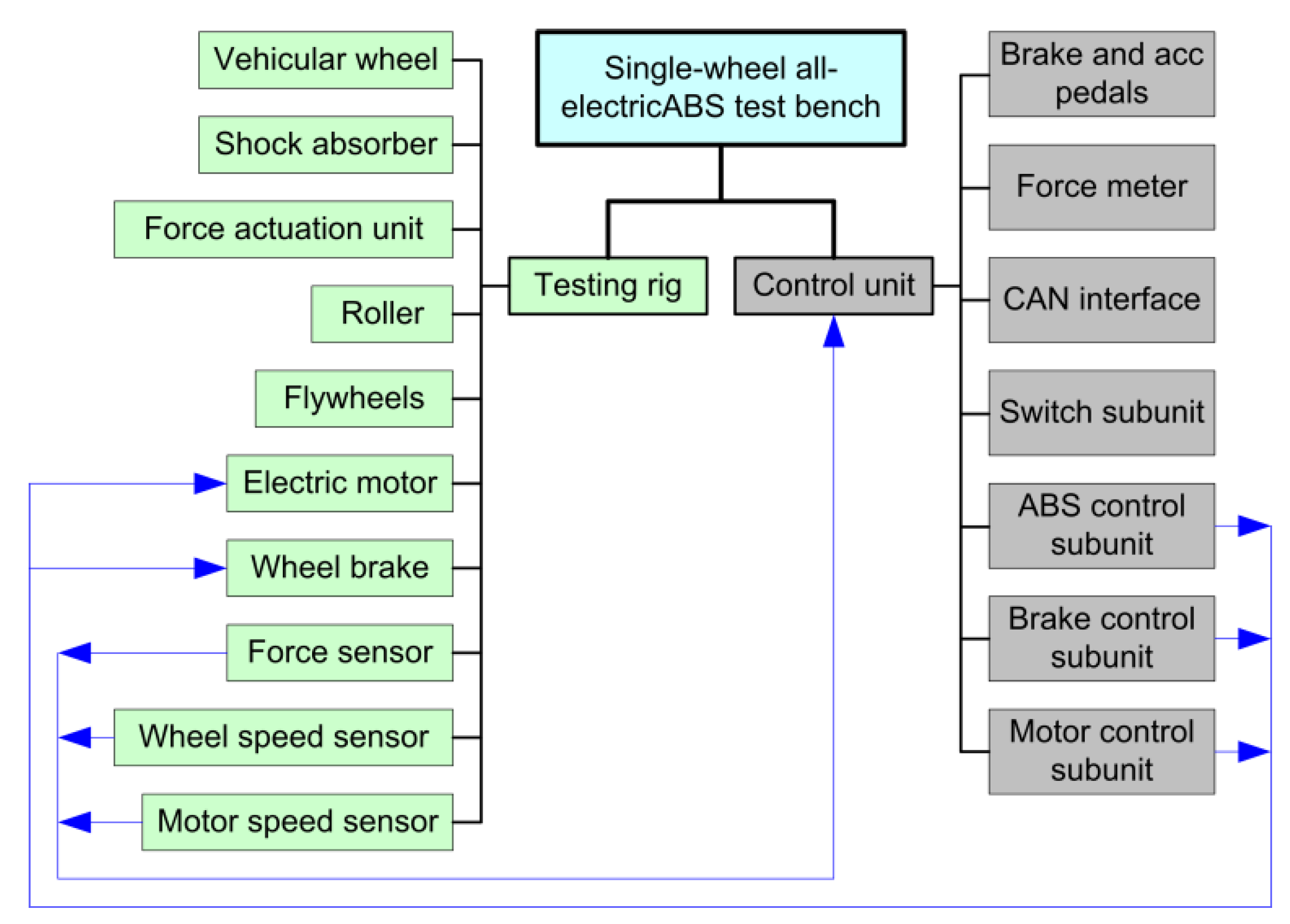
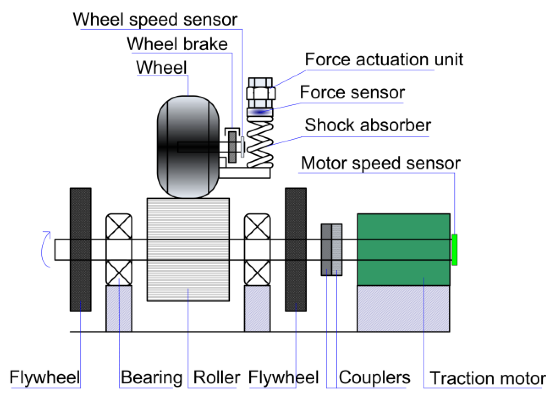
3. Scheme of Proposed Single-Wheel All-Electric ABS Test Bench

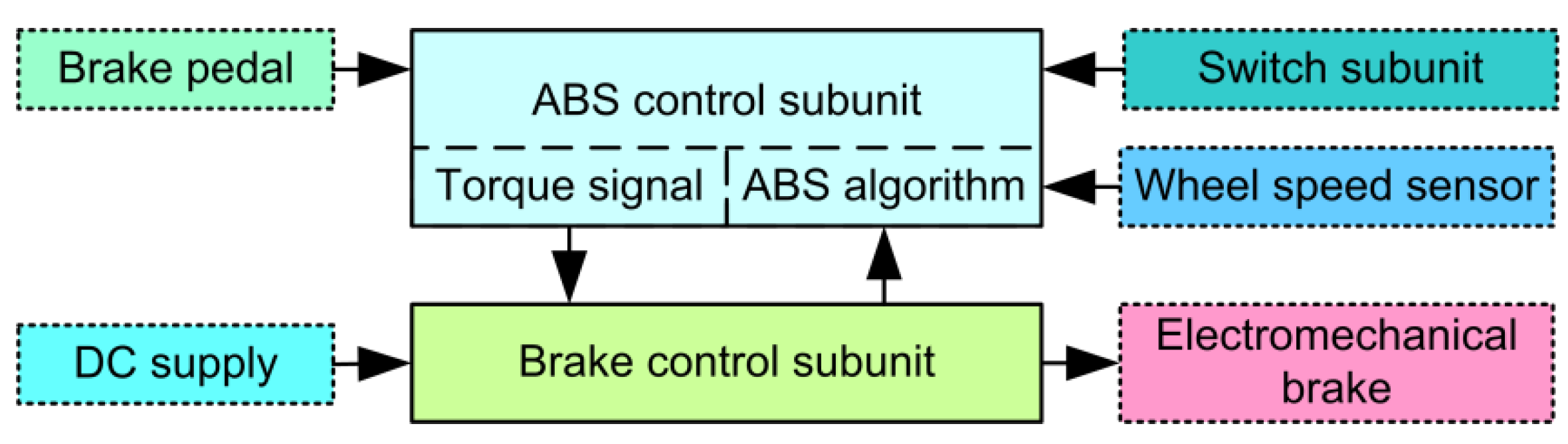
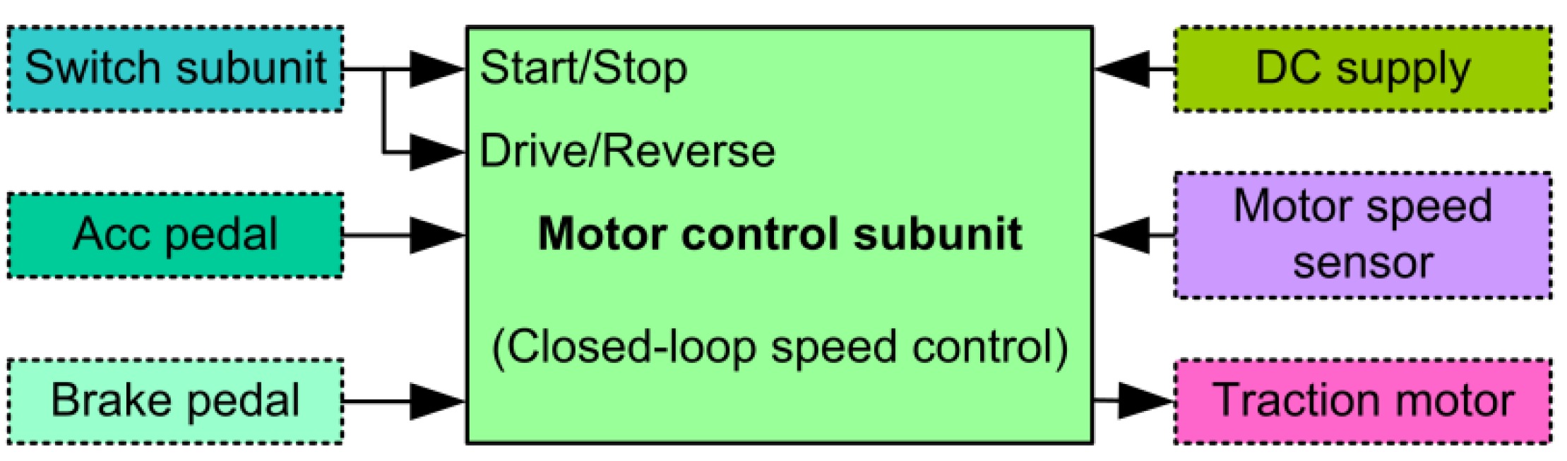
3.1. Schematic Structure of Proposed Single-Wheel ABS Test Bench

The proposed single-wheel all-electric ABS test bench consists of the testing rig and the control unit. The former is used to simulate the dynamic operation of the quarter vehicle model during braking, and mainly includes the vehicle wheel consisting of the real rim and the real tire, the real wheel brake, the real wheel speed sensor, the real shock absorber, the force sensor, the force actuation unit, the roller, the flywheels, the electric motor, the motor speed sensor, and the mechanical accessory. The latter is used to receive the operating instructions, control the traction motor and the electromechanical wheel brake, measure the required variables and output the required variables via Controller Area Network (CAN) communication. Furthermore, it mainly includes the ABS control subunit, the brake control subunit, the motor control subunit, the CAN interface, the force meter, the brake and acceleration pedals, and the switch subunit. The schematic structure of the proposed single-wheel all-electric ABS test bench is shown in Figure 1. Figure 2 illustrates the concept design of the testing rig.
Referring to Figure 1 and Figure 2, the wheel, the wheel brake, the wheel speed sensor, and the shock absorber in the test bench should select the real components of the commercial cars, respectively. The force actuation unit can apply the required vertical force to the wheel, which may be changed via the actuation unit. On the one hand, the roller surface is used to simulate the road surface. Consequently, various roller surfaces from different designs can simulate the required road surfaces. The contact between the tire and the roller surface can represent the one between the real tire and the real road surface. Furthermore, the roller’s circumferential velocity represents the longitudinal vehicle velocity. Consequently, the braking distance can be estimated via the roller’s circumferential velocity and the braking time. The roller is driven by the traction motor. Due to the friction between the roller surface and the tire, the wheel’s circumferential velocity is equal to the roller’s circumferential velocity without skidding. In addition, the initial roller speed (longitudinal vehicle velocity) and the initial wheel speed at braking can be controlled via the motor control subunit. The use of the flywheels in the test bench is to ensure that the kinetic energy of all the rotary components in the test bench approximately matches the quarter of the one of commercial vehicle model. Due to the selection of the real tire and the real wheel brake, the conditions of both the tire and the wheel brake in the test bench can represent the real conditions of the tire and brake, such as the aging of the tire and fading of the wheel brake

3.2. Model of Proposed Single-Wheel ABS Test Bench

From the view of physical meaning, the braking is to dissipate the kinetic energy of a vehicle within as short a time as possible. The kinetic energy of a vehicle when driving includes the kinetic energy arising from the linear motion of the vehicle body and the kinetic energy arising from the rotary components in the vehicle (such as the wheels). Considering that there are four wheel brakes in a vehicle, thus, the kinetic energy (Eb) of the rotary components in the proposed single-wheel ABS test bench should be equal to the quarter of the kinetic energy of the commercial car, expressed as,
E b = 1 4 E v
If a vehicle is driven at the longitudinal velocity (v) on a road, the kinetic energy of the vehicle can be expressed as
E v = 0.5 m v v 2 + 0.5 ( J f l w ω f l w 2 + J f r w ω f r w 2 + J r l w ω r l w 2 + J r r w ω r r w 2 ) + 0.5 J d ω d 2
where mv represents the mass of the vehicle, Jflw the moment of inertia of the front left wheel, ωflw the angular speed of the front left wheel, Jfrw the moment of inertia of the front right wheel, ωfrw the angular speed of the front right wheel, Jrlw the moment of inertia of the rear left wheel, ωrlw the angular speed of the rear left wheel, Jrrw the moment of inertia of the rear right wheel, ωrrw the angular speed of the rear right wheel, Jd the moment of inertia of the drivetrain, and ωd the angular speed of the drivetrain.
Assuming that four wheels have the same moment of inertia and the same angular speed, Equation (2) can be simplified as
E v = 0.5 m v v 2 + 2 J w ω w 2 + 0.5 J d ω d 2
where Jw represents the moment of inertia of a wheel and ωw the angular speed of a wheel.
In addition, the relationship between the longitudinal vehicle velocity and the angular wheel speed before braking can be given as
v = r w v ω w
where rwv is the radius of the vehicle wheel.
For the vehicle with four wheel brakes, hence, the kinetic energy of the quarter model of the vehicle is expressed as
E v q = 0.125 m v v 2 + 0.5 J w ω w 2 + 0.125 J d ω d 2
The kinetic energy of the rotary components of the proposed test bench can be computed as
E b = 0.5 J f w b ω f w b 2 + 0.5 J r b ω r b 2 + 0.5 J w b ω w b 2 + 0.5 J m b ω m b 2
where Jfwb denotes the moment of inertia of the total flywheels, ωfwb the angular speed of the flywheel, Jrb the moment of inertia of the roller, ωrb the angular speed of the roller, Jwb the moment of inertia of the wheel, ωwb the angular speed of the wheel, Jmb denotes the moment of inertia of the traction motor, and ωmb the angular speed of the motor shaft.
For the proposed test bench, the traction motor is to drive the roller and the total flywheels. They are coupled mechanically via the shaft. Thus, they have the same angular speed. Before braking, the wheel rotates due to the static friction between the wheel tire and the roller. Consequently, the circumferential velocity of the wheel is equal to that of the roller.
Hence, one has
ω r b = ω w b = ω m b
v w b = v r b
r w b ω w b = r r b ω r b
where vwb represents the circumferential velocity of the wheel, vrb the circumferential velocity of the roller, rwb the radius of the wheel, and rrb the radius of the roller.
Consequently, Equation (6) can be changed as
E b = 0.5 J f w b ω r b 2 + 0.5 J r b ω r b 2 + 0.5 J w b ω w b 2 + 0.5 J m b ω r b 2
The wheel in the proposed test bench is the same as the wheel of the real vehicle. Thus, the moment of inertia of the vehicle wheel is equal to that of the wheel in the test bench, expressed as
J w = J w b
Furthermore, the longitudinal vehicle velocity is equal to the circumferential velocity of the roller in the test bench. Thus, the angular speed of the vehicle wheel is equal to that of the wheel in the test bench. These can be expressed as
v = v w b = v r b
ω w = ω w b
Assuming that the kinetic energy of the quarter-drivetrain is equal to the kinetic energy of the traction motor in the test bench, it can be expressed as
0.125 J d ω d 2 = 0.5 J m b ω r b 2
Substituting Equations (5) and (10)–(14) into (1), hence, one has
0.125 m v v 2 = 0.5 J f w b ω r b 2 + 0.5 J r b ω r b 2
Consequently, the total moments of inertia of the roller and the flywheels are computed as
J f w b + J r b = 0.25 m v r r b 2
Therefore, the dimensions of the roller and the flywheels can be designed from (16). Thereby, it can be seen that the proposed single-wheel all-electric ABS test bench can simulate the operations of the real vehicle wheel and brake, the ABS methods/algorithms can be examined and evaluated in the laboratory at different braking velocities, different road surfaces, different vehicle loads, different conditions of the wheel brake and different tire conditions, and the performance of the ABS methods/algorithms can be acquired via the data output by the CAN port, such as the braking distance, the roller’s circumferential velocity (longitudinal vehicle velocity), the wheel’s circumferential velocity (wheel speed), and the wheel slip. Therefore, the proposed scheme meets the aforementioned requirements on the single-wheel ABS test bench.

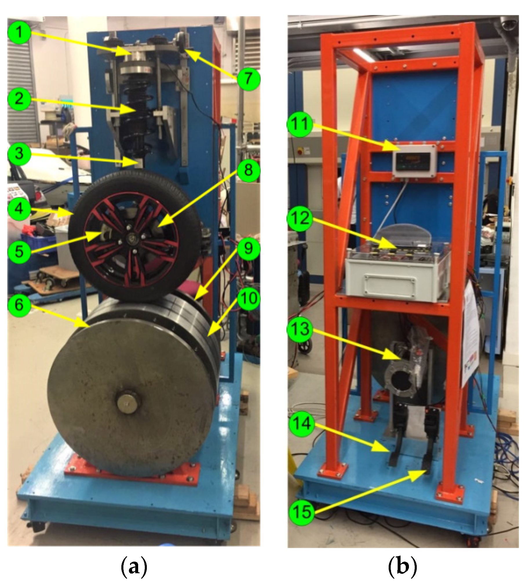
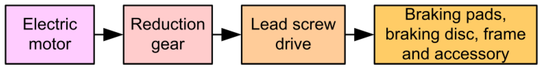
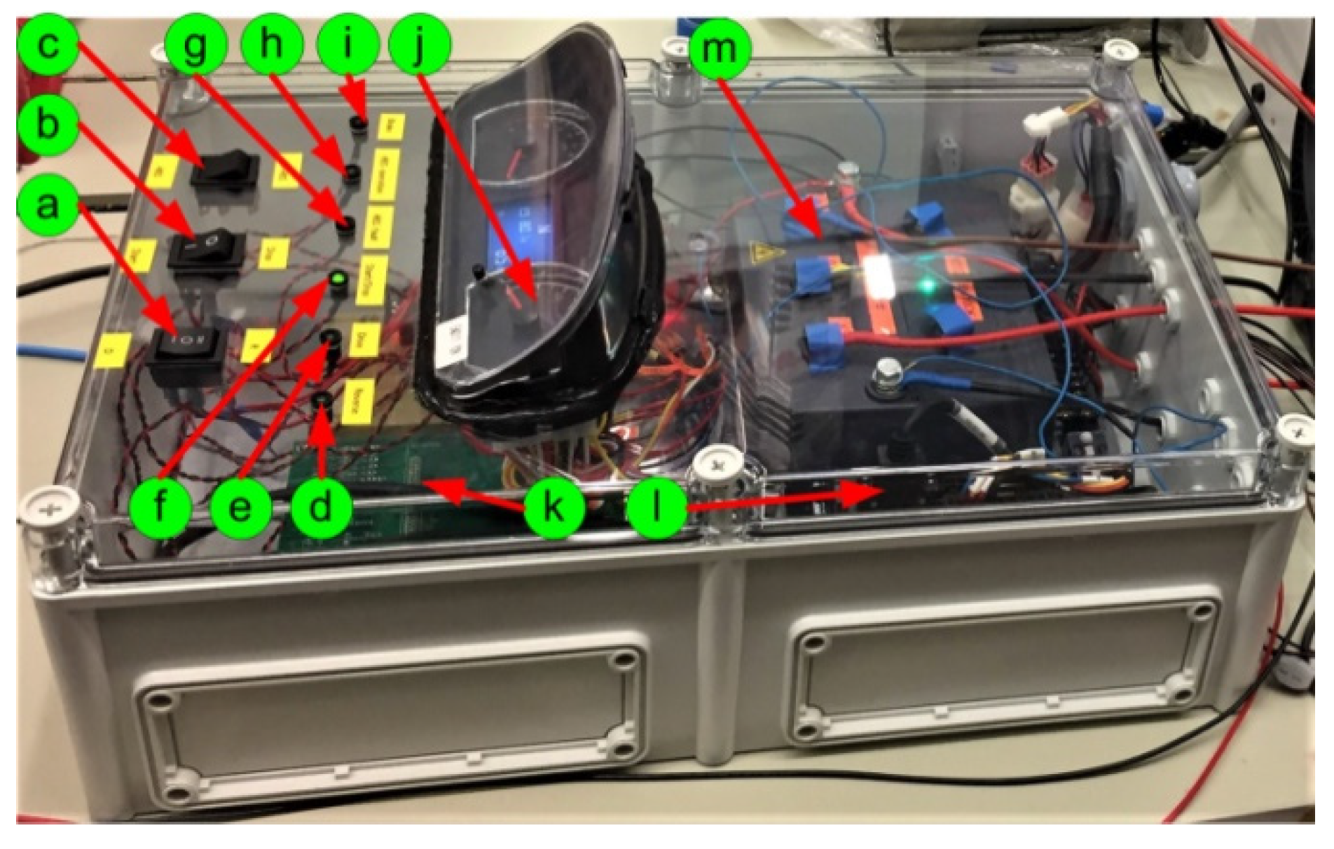
4. Developed Single-Wheel All-Electric ABS Test Bench
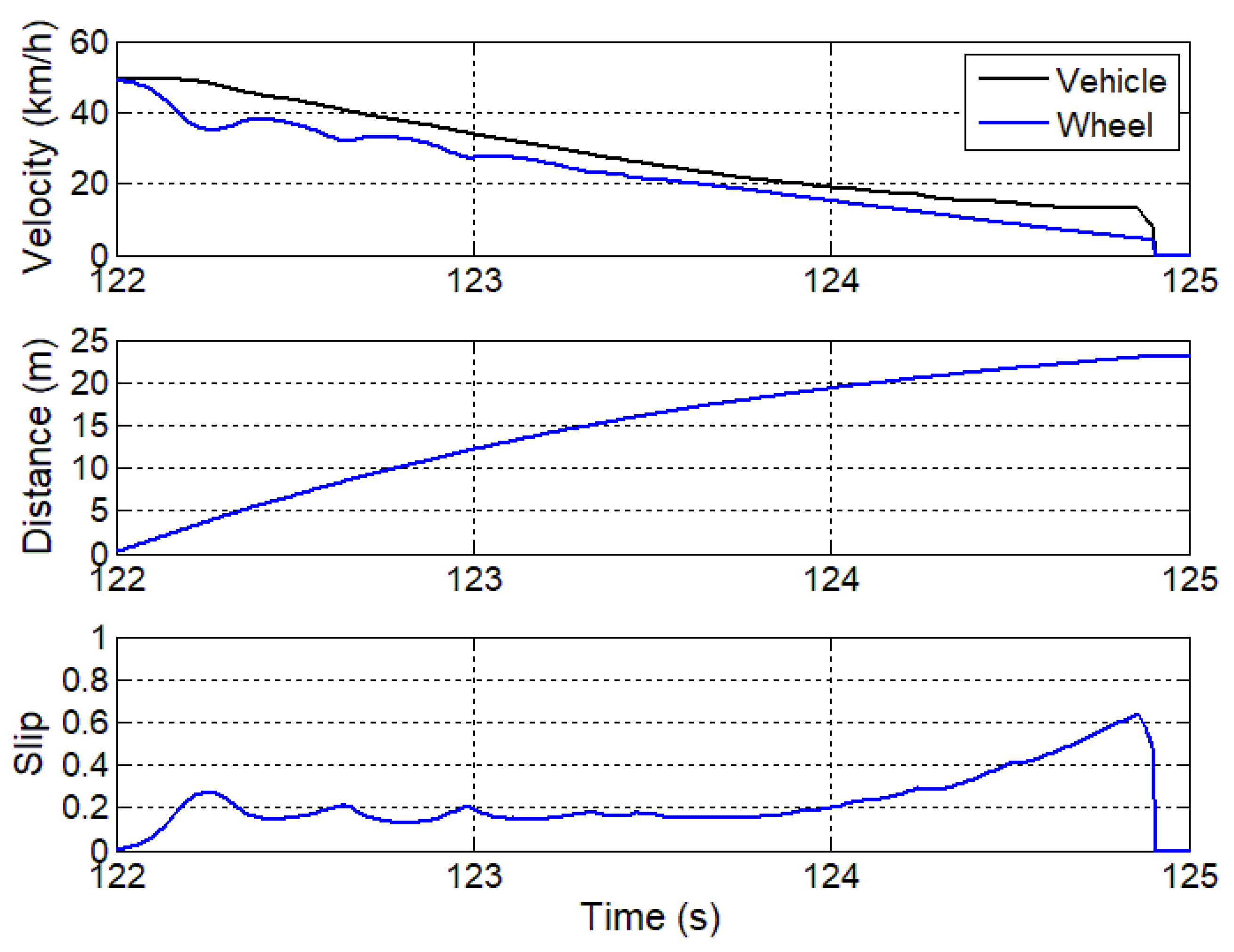
The developed prototype of the single-wheel all-electric ABS test bench is shown in Figure 3 and Figure 4, in which ① is the force sensor, ② the shock absorber, ③ the hub support, ④ the wheel, ⑤ the electromechanical brake (EMB), ⑥ the flywheel, ⑦ the force actuation unit, ⑧ the braking disc, ⑨ the flywheel, ⑩ the roller, ⑪ the force meter, ⑫ the control unit, ⑬ the traction motor, ⑭ the brake pedal, ⑮ the acceleration pedal, ⑯ the directional supporting rod, and ⑰ the supporting arm.
In this article, the wheel brake is the developed electromechanical brake. Thereby, the ABS in the prototype belongs to the all-electric ABS. The wheel, the shock absorber, the hub support, the braking pads, the braking disc, the directional supporting rod and the supporting arm are selected as the real components of the commercial car BYD-F0. The design of the roller and the flywheels is to ensure that the kinetic energy of all the rotary components in the test bench is approximately equal to the one of the quarter car model at a braking velocity. The rated clamping force of the developed electromechanical brake is 11 kN, which is the same as that of the electrohydraulic brake (EHB) in the commercial car BYD-F0. Consequently, the developed test bench is able to simulate the dynamic behavior of the real wheel and brake of the commercial car BYD-F0. The roller’s circumferential velocity and the wheel’s circumferential velocity in the developed test bench represent the longitudinal velocity of the real vehicle and the wheel’s circumferential velocity of the real vehicle, respectively. In the prototype, the roller is made of the aluminum alloy and the roller’s surface is polished. Thus, the road condition in the developed test bench belongs to the slippery road. In the future, the real road surfaces should be simulated through the different designs of the roller surfaces. The main parameters of the prototype are listed in Table 1.
The developed electromechanical brake consists of the electric motor, the reduction gear, the lead screw drive, the braking pads, the braking disc, the brake frame and the accessory, as shown in Figure 5. The output torque of the motor can be changed through controlling the torque signal voltage of the brake control subunit. Consequently, the clamping force output by the EMB can be controlled via the reduction gear and the lead screw drive. The clamping force is approximately proportional to the output torque of the brake motor.
The ABS control subunit is based on the microcontroller unit (MCU) system board STM32F446xC/E. The ABS control subunit is used to receive the braking signal from the electric brake pedal, the ABS operation signal from the switch subunit, the wheel speed signal from the wheel speed sensor and the fault signal from the brake control subunit, to execute the ABS algorithm or the braking algorithm without ABS, and to output the torque signal to the brake control subunit. The schematic of the ABS control subunit is illustrated in Figure 6.
The brake control subunit receives the torque signal from the ABS control subunit, outputs the fault signal to the ABS control subunit, and controls the torque magnitude and the torque direction of the brake motor. Thereby, the clamping force of the electromechanical brake can be changed. The schematic of the brake control subunit is illustrated in Figure 6.
The motor control subunit receives the start/stop signal from the switch subunit, the drive/reverse signal from the switch subunit, the acceleration signal from the acceleration pedal and the motor speed signal from the motor speed sensor, controls the magnitude and direction of the traction motor speed, and implements the closed-loop speed control. Figure 7 shows the interface of the motor control subunit.
The switch subunit provides the operating instructions including the braking instruction with/without ABS to the ABS control subunit, the start/stop instruction to the motor control subunit, and the drive/reverse direction instruction to the motor control subunit, and displays the traction motor speed and the operating status including the braking operation, the ABS operation, the ABS fault, the start/stop, the drive operation, and the reverse operation.
The maximum sampling rate of 12-bit A/D converters in the ABS subunit reaches 2.4 Megasamples per second (MSPS), which fully meets to acquire any analog signals in the test bench. Consequently, the signal bandwidth of the test bench fully depends on the speed sensor of the wheel and the relevant filter. In the developed test bench, the speed sensor of the wheel is the one in the commercial car BYD-F0 and the speed signal of the motor is from the output of the commercial motor inverter. The measurable bandwidth of the wheel speed is 4 Hz–2 kHz and the one related to the motor speed is 2.5 Hz–50 kHz.
The developed control unit is shown in Figure 8, in which ⓐ is the drive/reverse switch, ⓑ the start/stop switch, ⓒ the ABS/Non-ABS switch, ⓓ the reverse indicator light, ⓔ the drive indicator light, ⓕ the start/stop indicator light, ⓖ the ABS fault indicator light, ⓗ the ABS operation indicator light, ⓘ the braking indicator light, ⓙ the motor speed meter, ⓚ the ABS control subunit, ⓛ the brake control subunit, and ⓜ the motor control subunit.

5. Application

The developed single-wheel all-electric ABS test bench was applied to demonstrate the performance of the ABS algorithm. Figure 9 shows the measured ABS operation under the ABS control, in which the initial braking velocity (the roller’s circumferential velocity) is 50 km/h and the vertical force to the wheel is 175 kg. The measured data are transferred by the CAN port of the test bench. The experimental results show that the developed single-wheel all-electric ABS test bench demonstrates the operation of the all-electric antilock braking system successfully.
The tire-road adhesion coefficient plays a key role in ABS performance. It mainly depends on the road surfaces. Consequently, the different road surfaces result in the various adhesion coefficients. In the proposed test bench, the roller surface of the aluminum alloy is to simulate a road condition. To obtain the various adhesion coefficients, thereby, the different degrees of the smoothness and the different materials of the roller surface should be designed. It shall be the future study.

6. Conclusions

This paper proposes a technical scheme to develop the single-wheel all-electric ABS test bench. The technology is based on the proposed model, in which the kinetic energy of the total rotary components in the bench matches the kinetic energy of a real car when braking. From the model, the design formulas of the roller and the flywheels can be derived. The developed single-wheel all-electric ABS test bench is able to simulate the dynamic behavior of the real wheel of the commercial car and the operation of the all-electric ABS. It may provide the repetitive tests with the variables, such as the different braking velocities, the different vertical forces to the wheel, the different tire conditions, the different conditions of braking pads and disc, and the different road surfaces. It is low cost and compact, and is a prior solution to demonstrating, evaluating, and verifying ABS methods/algorithms in a laboratory. It can save cost and time for the subsequent tests on ABS on real road.

Author Contributions

Methodology, system design, experiment and writing—original draft preparation, X.X.; methodology, supervision and writing—review, K.W.E.C.; mechanical design, W.W.C.; control unit, software and experiment, Y.C.F.; control unit and experiment, K.L.J.K.; and electromechanical brake and mechanical design, Y.F. All authors have read and agreed to the published version of the manuscript.

Funding

This research was funded partly by the Guangdong-Hong Kong Technology Cooperation Funding Scheme of Hong Kong Innovation and Technology Support Programme, grant number GHP/033/17AP, and university research project 845G.

Institutional Review Board Statement

Not applicable.

Informed Consent Statement

Not applicable.

Acknowledgments

The authors would like to thank S. Raghu Raman for the support in the experiment.

Conflicts of Interest

The authors declare no conflict of interest. The funders had no role in the design of the study; in the collection, analyses, or interpretation of data; in the writing of the manuscript, or in the decision to publish the results.

References

  1. Guo, J.; Jian, X.; Lin, G. Performance Evaluation of an Anti-Lock Braking System for Electric Vehicles with a Fuzzy Sliding Mode Controller. Energies 2014, 7, 6459–6476. [Google Scholar] [CrossRef] [Green Version]
  2. Juan, A.C.; Antonio, O.; Juan, J.C.; Antonio, S. A Fuzzy Logic Control for Antilock Braking System Integrated in the IMMa Tire Test Bench. IEEE Trans. Veh. Technol. 2005, 54, 1937–1949. [Google Scholar]
  3. Shim, T.; Chang, S.; Lee, S. Investigation of Sliding-Surface Design on the Performance of Sliding Mode Controller in Antilock Braking Systems. IEEE Trans. Veh. Technol. 2008, 57, 747–759. [Google Scholar] [CrossRef]
  4. Patil, A.; Ginoya, D.; Shendge, P.D.; Phadke, S.B. Uncertainty-Estimation-Based Approach to Antilock Braking Systems. IEEE Trans. Veh. Technol. 2015, 65, 1171–1185. [Google Scholar] [CrossRef]
  5. Sun, J.H.; Xue, X.D.; Cheng, K.W.E. Fuzzy Sliding Mode Wheel Slip Ratio Control for Smart Vehicle Anti-Lock Braking System. Energies 2019, 12, 2501. [Google Scholar] [CrossRef] [Green Version]
  6. Hoseinnezhad, R.; Bab-Hadiashar, A. Efficient Antilock Braking by Direct Maximization of Tire–Road Frictions. IEEE Trans. Ind. Electron. 2010, 58, 3593–3600. [Google Scholar] [CrossRef]
  7. Morselli, R.; Zanasi, R. Self-Tuning Control Strategy for Antilock Braking Systems. In Proceedings of the 2006 American Control Conference, Minneapolis, MN, USA, 14–16 June 2006; pp. 5861–5866. [Google Scholar]
  8. Han, K.; Lee, B.; Choi, S.B. Development of an antilock brake system for electric vehicles without wheel slip and road friction information. IEEE Trans. Veh. Technol. 2019, 68, 5506–5517. [Google Scholar] [CrossRef]
  9. Sun, J.H.; Xue, X.D.; Cheng, K.W.E. Four-Wheel Anti-Lock Braking System with Robust Adaptation under Complex Road Conditions. IEEE Trans. Veh. Technol. 2021, 70, 292–302. [Google Scholar] [CrossRef]
  10. Tomasikova, M.; Tropp, M.; Gajdosik, T.; Krzywonos, L.; Brumercik, F. Analysis of transport mecha-tronic system properties. Procedia Eng. 2017, 192, 881–886. [Google Scholar] [CrossRef]
  11. Pugi, L.; Grasso, F.; Pratesi, M.; Cipriani, M.; Bartolomei, A. Design and preliminary performance evaluation of a four wheeled vehicle with degraded adhesion conditions. Int. J. Electr. Hybrid Veh. 2017, 9, 1–32. [Google Scholar] [CrossRef]
  12. Oniz, Y.; Kayacan, E.; Kaynak, O. A Dynamic Method to Forecast the Wheel Slip for Antilock Braking System and Its Experimental Evaluation. IEEE Trans. Syst. Man Cybern. Part B Cybern. 2009, 39, 551–560. [Google Scholar] [CrossRef] [PubMed] [Green Version]
  13. Khatun, P.; Bingham, C.M.; Schofield, N.; Mellor, P.H. An Experimental Laboratory Bench Setup to Study Electric Vehicle Antilock Braking/Traction Systems and their Control. In Proceedings of the IEEE 56th Vehicular Technology Conference, Vancouver, BC, Candad, 24–28 September 2002; Volume 3, pp. 1490–1494. [Google Scholar]
  14. Horn, M.; Zehetner, J. A Brake-Testbench for Research and Education. In Proceedings of the 16th IEEE International Conference on Control Applications, Singapore, 1–3 October 2007; pp. 444–448. [Google Scholar]
  15. Huang, D.; Shen, J. Study on Mathematical Model of Test Bench for Vehicle Anti-Lock Braking System. In Proceedings of the 2009 Second International Conference on Intelligent Computation Technology and Automation, Changsha, China, 10–11 October 2009; pp. 268–270. [Google Scholar]
  16. Wang, R.; Wang, B.; Sun, H. Development of a Single wheel Test Bench for Anti-lock Brake System. In Proceedings of the 2010 International Conference on Optoelectronics and Image Processing, Hainan, China, 11–12 November 2010; pp. 429–431. [Google Scholar]
  17. Hao, R.; Zhao, X.; Xu, Z. Auto Anti-lock Braking System Bench Test Results Classification Model Based on Neural Network. In Proceedings of the 2011 International Conference on Electronics, Communications and Control (ICECC), Ningbo, China, 9–11 September 2011; pp. 758–761. [Google Scholar]
  18. Zhang, Z.; Cheung, N.C.; Cheng, K.W.E.; Xue, X.D.; Lin, J.K. Longitudinal and Transversal End-Effects Analysis of Linear Switched Reluctance Motor. IEEE Trans. Ind. Electron. 2019, 67, 3990–4001. [Google Scholar] [CrossRef]
  19. Tavernini, D.; Vacca, F.; Metzler, M.; Savitski, D.; Ivanov, V.; Gruber, P.; Hartavi, A.E.; Dhaens, M.; Sorniotti, A. An explicit nonlinear model predictive ABS controller for electro-hydraulic braking systems. IEEE Trans. Ind. Electron. 2020, 67, 3990–4001. [Google Scholar] [CrossRef]
  20. Reif, K. Brakes, Brake Control and Driver Assistance Systems: Function, Regulation and Components; Springer Fachmedien Wiesbaden: Hessen, Deutschland, 2014; pp. 22–23. [Google Scholar]
Figure 1. Block diagram of proposed single-wheel all-electric ABS test bench.
Energies 14 01294 g001
Figure 2. Schematic design of testing rig.
Energies 14 01294 g002
Figure 3. Prototype of developed single-wheel all-electric ABS test bench: (a) Front view; (b) Rear view.
Energies 14 01294 g003
Figure 4. Partial view of developed single-wheel all-electric ABS test bench.
Energies 14 01294 g004
Figure 5. Schematic structure of developed electromechanical brake.
Energies 14 01294 g005
Figure 6. Block diagram of ABS and brake control subunits.
Energies 14 01294 g006
Figure 7. Block diagram of motor control subunit.
Energies 14 01294 g007
Figure 8. Prototype of developed control unit for proposed test bench.
Energies 14 01294 g008
Figure 9. ABS variables measured by developed test bench.
Energies 14 01294 g009
Table 1. Main parameters of developed prototype.
ParameterValue
Model of commercial carBYD-F0
Nominal car mass870 kg
Tire model165/60 R14
Nominal radius of tire0.276 m
Force actuation unit0–300 kg
Rated clamping force of EMB11 kN
Model of traction motorInduction motor
Rated power of motor5 kW
Rated speed of motor3000 rpm
Material of roller surfaceAluminum alloy
External diameter of roller0.680 m
Thickness of roller0.274 m
Material of roller sideAluminum alloy
Out-diameter of roller side0.680 m
Thickness of roller side0.180 m
Roller surfacePolished
Material of flywheelsStructural steel
Out-diameter of flywheel0.670 m
Thickness of flywheel0.028 m
Height of stand frame1.840 m
Length of stand frame0.600 m
Width of stand frame0.600 m
Publisher’s Note: MDPI stays neutral with regard to jurisdictional claims in published maps and institutional affiliations.

