
Robust Power Sharing and Voltage Stabilization Control Structure via Sliding-Mode Technique in Islanded Micro-Grid


Abstract
1. Introduction
- (i)
- More accurate active power sharing during both the transient and steady states can be ensured, and smaller voltage amplitude deviation can be achieved due to the proposed TSMC-based P-U droop control scheme. Moreover, the active power sharing and the voltage amplitude are insensitive to system hardware parameters.
- (ii)
- Strong robustness and better voltage tracking property can be obtained due to the PID-type TSMC scheme for the inner capacitance-voltage control.
- (iii)
- The TSMC-based frameworks for both the inner voltage loop and the droop control loop endow the system with the performances of fast dynamic response, high control precision and strong robustness to uncertainties.
- (iv)
- The small-signal model of the TSMC-based droop-controlled system gives detailed analyses of the parameter influence on the system stability and the dynamic responses.
2. Basic Description of Droop Control Method
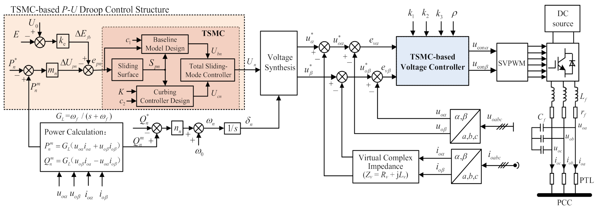
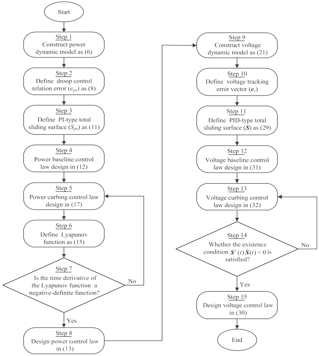
3. Proposed TSMC-Based Power and Voltage Control Structure
3.1. TSMC-Based P-U Droop Control Scheme
3.2. TSMC-Based Voltage Control Scheme
4. Small-Signal Model and Stability Analysis
5. Numerical Simulations and Experimental Results
5.1. Numerical Simulations
5.1.1. Power Sharing Performance Verification
5.1.2. Influence of ke, m and n on Power Sharing Performance
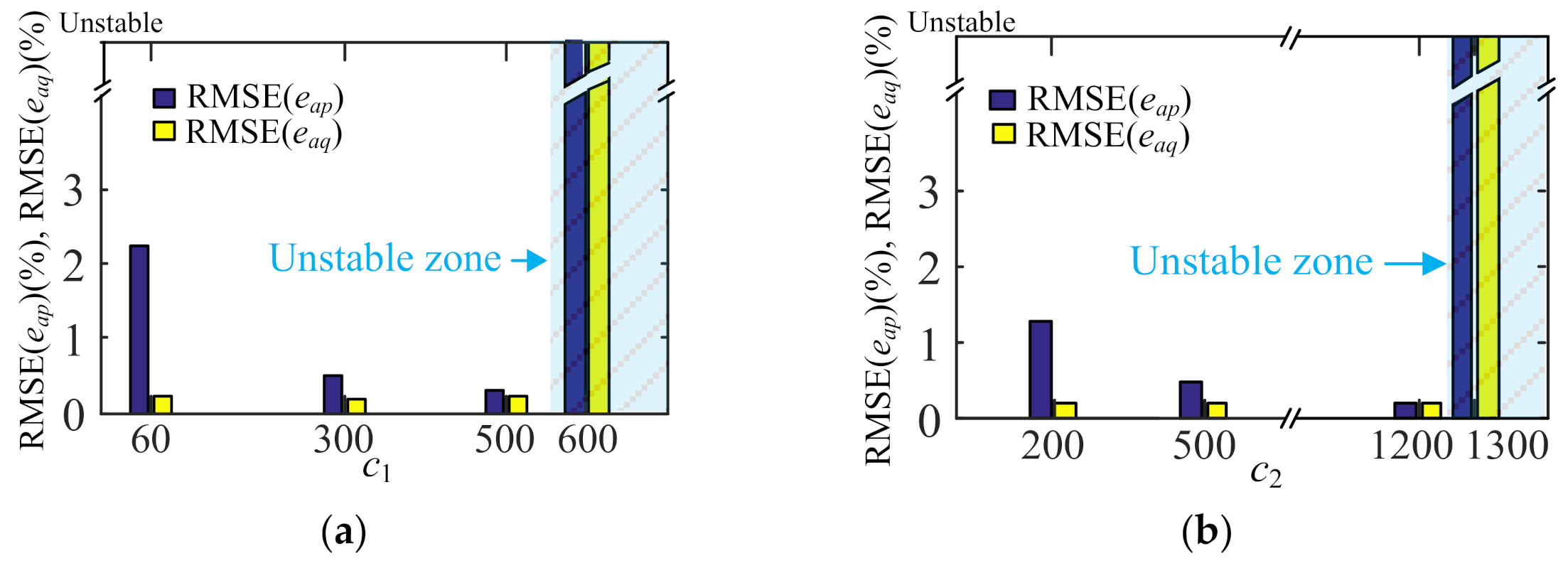
5.1.3. Influence of c1 and c2 on Power Sharing Performance
5.1.4. Influence of K and c2 on Chattering Phenomena
5.1.5. Comparison Study
5.2. Experimental Results
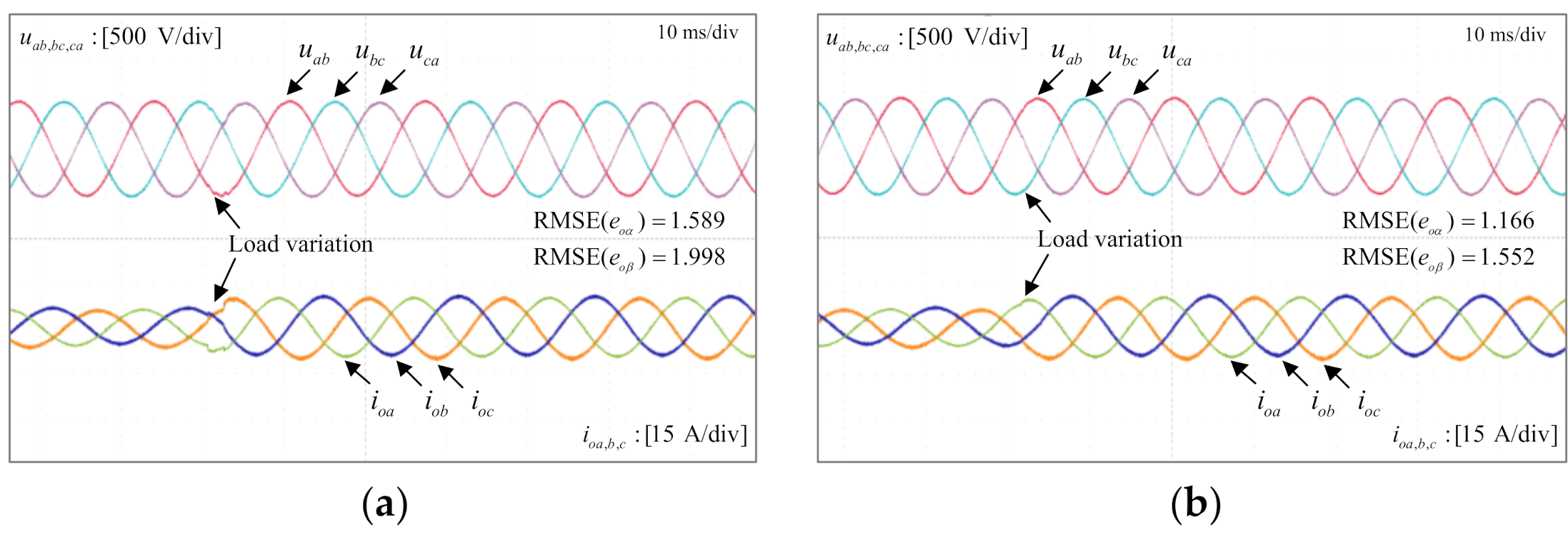
5.2.1. Performance Verification of TSMC-Based Voltage Controller
5.2.2. Performance Verification of Proposed TSMC-Based Droop Control Method
- Case I: Equal load power sharing with line impedance ratio of 2:1
- Case II: Equal load power sharing with line impedance ratio of 3:1
- Case III: Power sharing with different inverter capacity
6. Conclusions
Author Contributions
Funding
Institutional Review Board Statement
Informed Consent Statement
Data Availability Statement
Conflicts of Interest
Nomenclature
| Abbreviations | |
| DGs | Distributed generations |
| DSP | Digital signal processor |
| ESR | Equivalent series resistance |
| EMU | Energy management unit |
| FPGA | Field programmable gate array |
| MG | Micro-grid |
| MPC | Model predictive control |
| PI | Proportional-integral |
| PID | Proportion-integration-differentiation |
| PTL | Power transmission lines |
| PCC | Point of common coupling |
| PWM | Pulse-width-modulation |
| PRC | Proportional-resonant controller |
| RMSE | Root-mean-squared error |
| SAPFs | Shunt active power filters |
| SVPWM | Space-vector PWM |
| TSMC | Total sliding-mode control |
| VOT | Vector operation technique |
| VSI | Voltage source inverter |
| P-f | Active power-frequency |
| P-U | Active power-voltage |
| Q-f | Reactive power-frequency |
| Q-U | Reactive power-voltage |
| Variables and parameters | |
| Pn | Output active power |
| Qn | Output reactive power |
| Un | Voltage amplitude of DGn |
| ωn | Angle frequency of DGn |
| E | Voltage amplitude of PCC |
| Measured active power | |
| Measured reactive power | |
| δn | Phase angle of DGn |
| δc | Phase angle of PCC |
| Udc | DC-link voltage of DG |
| uoα, uoβ | Capacitance-voltage components of α and β axis |
| ioα, ioβ | Output currents in α and β axis |
| uconα, uconβ | Control efforts of α and β axis |
| Spn | Total sliding surface for power control loop |
| S | Total sliding surface for voltage control loop |
| U0 | Rated voltage amplitude |
| ω0 | Rated angular frequency |
| Rated active power | |
| Rated reactive power | |
| , | Voltage commands generated by droop controller |
| , | Capacitance voltage references of α and β axis |
| ωf | Cutoff frequency of low-pass filter for power |
| mn | Droop coefficient of P-U |
| nn | Droop coefficient of Q-f |
| ke | Proportional factor of U0-E feedback loop |
| c1, K, c2 | Control parameters of TSMC-based droop controller |
| k1, k2, ρ, c3 | Control parameters of TSMC-based voltage controller |
| KPWM | PWM gain |
| Rv | Virtual resistance of DGn |
| Lv | Virtual inductance |
| Rn | Line resistance |
| Lf | Filter inductor |
| Cf | Filter capacitor |
| rf | ESR of filter inductor |
References
- Afshar, Z.; Mollayousefi, M.; Bathaee, S.M.T.; Bina, M.T.; Gharehpetian, G.B. A novel accurate power sharing method versus droop control in autonomous microgrids with critical loads. IEEE Access 2019, 7, 89466–89474. [Google Scholar] [CrossRef]
- Zhang, W.; Wang, W.; Liu, H.; Xu, D. A disturbance rejection control strategy for droop-controlled inverter based on super-twisting algorithm. IEEE Access 2019, 7, 27037–27046. [Google Scholar] [CrossRef]
- Hossain, M.A.; Pota, H.R.; Issa, W.; Hossain, M.J. Overview of AC microgrid controls with inverter-interfaced generations. Energies 2017, 10, 1300. [Google Scholar] [CrossRef]
- Yu, K.; Ai, Q.; Wang, S.; Ni, J.; Lv, T. Analysis and optimization of droop controller for microgrid system based on small-signal dynamic model. IEEE Trans. Smart Grid 2015, 7, 695–705. [Google Scholar] [CrossRef]
- Wang, K.; Yuan, X.; Geng, Y.; Wu, X. A practical structure and control for reactive power sharing in microgrid. IEEE Trans. Smart Grid 2019, 10, 1880–1888. [Google Scholar] [CrossRef]
- Chen, T.; Abdel-Rahim, O.; Peng, F.; Wang, H. An improved finite control set-MPC-based power sharing control strategy for islanded AC microgrids. IEEE Access 2020, 8, 52676–52686. [Google Scholar] [CrossRef]
- Yan, X.; Cui, Y.; Cui, S. Control method of parallel inverters with self-synchronizing characteristics in distributed microgrid. Energies 2019, 12, 3871. [Google Scholar] [CrossRef]
- He, J.; Du, L.; Liang, B.; Li, Y.; Wang, C. Coupled-virtual-impedance control for AC/DC hybrid microgrid power electronic interlinking unit with dual converters. IEEE Trans. Smart Grid 2019, 10, 3387–3400. [Google Scholar] [CrossRef]
- Tang, X.; Hu, X.; Li, N.; Deng, W.; Zhang, G. A novel frequency and voltage control method for islanded microgrid based on multienergy storages. IEEE Trans. Smart Grid 2016, 7, 410–419. [Google Scholar] [CrossRef]
- Pogaku, N.; Prodanovic, M.; Green, T.C. Modeling, analysis and testing of autonomous operation of an inverter-based microgrid. IEEE Trans. Power Electron. 2007, 22, 613–625. [Google Scholar] [CrossRef]
- Guerrero, J.M.; de Vicuna, L.G.; Matas, J.; Castilla, M.; Miret, J. Output impedance design of parallel-connected UPS inverters with wireless load sharing control. IEEE Trans. Ind. Electron. 2005, 52, 1126–1135. [Google Scholar] [CrossRef]
- Wang, X.F.; Li, Y.W.; Blaabjerg, F.; Zoh, P.C. Virtual-impedance-based control for voltage-source and current-source converters. IEEE Trans. Power Electron. 2015, 30, 7019–7037. [Google Scholar] [CrossRef]
- Guan, Y.; Guerrero, J.M.; Zhao, X.; Vasquez, J.C.; Guo, X.Q. A new way of controlling parallel-connected inverters by using synchronous-reference-frame virtual impedance loop-part I: Control principle. IEEE Trans. Power Electron. 2016, 31, 4576–4593. [Google Scholar] [CrossRef]
- Zhong, Q.C. Robust droop controller for accurate proportional load sharing among inverters operated in parallel. IEEE Trans. Ind. Electron. 2013, 60, 1281–1290. [Google Scholar] [CrossRef]
- Wai, R.J.; Zhang, Q.Q.; Wang, Y. A novel voltage stabilization and power sharing control method based on virtual complex impedance for off-grid microgrid. IEEE Trans. Power Electron. 2019, 34, 1863–1880. [Google Scholar] [CrossRef]
- Kahrobaeian, A.; Mohamed, Y.A.R.I. Networked-based hybrid distributed power-sharing and control for islanded microgrid systems. IEEE Trans. Power Electron. 2015, 30, 603–617. [Google Scholar] [CrossRef]
- Mahmud, K.; Sahoo, A.K.; Ravishankar, J.; Dong, Z.Y. Coordinated multilayer control for energy management of grid-connected AC microgrids. IEEE Trans. Ind. Appl. 2019, 55, 7071–7081. [Google Scholar] [CrossRef]
- Shan, Y.; Hu, J.; Liu, M.; Zhu, J.; Guerrero, J.M. Model predictive voltage and power control of islanded PV-battery microgrids with washout-filter-based power-sharing strategy. IEEE Trans. Power Electron. 2020, 35, 1227–1238. [Google Scholar] [CrossRef]
- Zhu, Y.X.; Zhuo, F.; Shi, H.T. Accurate power sharing strategy for complex microgrid based on droop control method. In Proceedings of the 2013 IEEE ECCE Asia Downunder, Melbourne, Australia, 3–6 June 2013; pp. 344–350. [Google Scholar]
- Wu, X.; Xu, Y.; He, J.; Wang, X.; Vasquez, J.C.; Guerrero, J.M. Pinning-based hierarchical and distributed cooperative control for AC microgrid clusters. IEEE Trans. Power Electron. 2020, 35, 9865–9885. [Google Scholar] [CrossRef]
- Yazdanian, M.; Mehrizi-Sani, A. A washout filter-based power sharing. IEEE Trans. Smart Grid 2016, 7, 967–968. [Google Scholar] [CrossRef]
- Ma, L.; Zhang, Y.F.; Yang, X.F.; Ding, S.H.; Dong, L.L. Quasi-continuous second-order sliding mode control of buck converter. IEEE Access 2018, 6, 17859–17867. [Google Scholar] [CrossRef]
- Han, Y.; Ma, R.; Cui, J. Adaptive higher-order sliding mode control for islanding and grid-connected operation of a microgrid. Energies 2018, 11, 1459. [Google Scholar] [CrossRef]
- Wang, Y.; Wai, R.J. Design of discrete-time backstepping sliding-mode control for LCL-type grid-connected inverter. IEEE Access 2020, 8, 95082–95098. [Google Scholar] [CrossRef]
- Vadi, S.; Padmanaban, S.; Bayindir, R.; Blaabjerg, F.; Mihet-Popa, L. A review on optimization and control methods used to provide transient stability in microgrids. Energies 2019, 12, 3582. [Google Scholar] [CrossRef]
- Wai, R.J. Development of intelligent position control system using optimal design technique. IEEE Trans. Ind. Electron. 2003, 50, 218–231. [Google Scholar]
- Morales, J.; Vicuna, L.G.; Guzman, R.; Castilla, M.; Miret, J. Modeling and sliding mode control for three-phase active power filters using the vector operation technique. IEEE Trans. Ind. Electron. 2018, 65, 6828–6838. [Google Scholar] [CrossRef]
- Guzman, R.; Vicuna, L.G.; Castilla, M.; Miret, J.; Hoz, J. Variable structure control for three-phase LCL-filtered inverters using a reduced converter model. IEEE Trans. Ind. Electron. 2018, 65, 5–15. [Google Scholar] [CrossRef]
- Vieira, R.P.; Martins, L.T.; Massing, J.R.; Stefanello, M. Sliding mode controller in a multiloop framework for a grid-connected VSI with LCL filter. IEEE Trans. Ind. Electron. 2018, 65, 4714–4723. [Google Scholar] [CrossRef]
- Mokhtar, M.; Marei, M.I.; EI-Sattar, A.A. An adaptive droop control scheme for DC microgrids integrating sliding mode voltage and current controlled boost converters. IEEE Trans. Smart Grid 2017, 10, 1685–1693. [Google Scholar] [CrossRef]
- Altin, N.; Ozdemir, S.; Komurcugil, H.; Sefa, I. Sliding-mode control in natural frame with reduced number of sensors for three-phase grid-tied LCL-interfaced inverters. IEEE Trans. Ind. Electron. 2019, 66, 2903–2913. [Google Scholar] [CrossRef]
- Delghavi, M.B.; Yazdani, A. Sliding-mode control of AC voltages and currents of dispatchable distributed energy resources in master-slave-organized inverter-based microgrids. IEEE Trans. Smart Grid 2019, 10, 980–991. [Google Scholar] [CrossRef]
- Wang, Y.; Wai, R.J. Adaptive power decoupling strategy for single-phase grid-connected converter. IEEE Trans. Ind. Appl. 2019, 55, 4275–4285. [Google Scholar] [CrossRef]
- Wai, R.J.; Lin, C.Y. Active low-frequency ripple control for clean-energy power-conditioning mechanism. IEEE Trans. Ind. Electron. 2010, 57, 3780–3792. [Google Scholar] [CrossRef]
- Hosseinzadeh, M.; Yazdanpanah, M.J. Performance enhanced model reference adaptive control through switching non-quadratic Lyapunov functions. Syst. Control. Lett. 2015, 76, 47–55. [Google Scholar] [CrossRef]
- Tao, G. Model reference adaptive control with L1+α tracking. Int. J. Control. 1996, 64, 859–870. [Google Scholar] [CrossRef]


| Control Methods | Main Contributions | Drawbacks |
|---|---|---|
| Virtual-impedance-based method [11,12,13] | Improve power sharing performance Easy to implement | Increase the voltage drop Poor robustness |
| PI-based droop control [14,15] | Accurate power sharing and voltage restorationRobust to line impedance | Dynamic performance to be further improved |
| Centralized control [1,19] | Simple structure Accurate power sharingVoltage and frequency restoration | Suffer from the problem of “single point of failure” for central control unit |
| Hierarchical control [16,17,20] | Accurate power sharing Voltage and frequency restoration Optimized power generation | Tradeoff between power sharing and voltage restoration |
| Washout-filter-based method [18,21] | Mitigate voltage and frequency deviation Communication-free | Poor robustness to line impedance Dynamic performance to be further improved |
| Parameter | Value |
|---|---|
| DC Voltage | Udc =700 V |
| AC Phase Voltage | 220 V(RMS)/60 Hz |
| Sampling Frequency | 10 kHz |
| LC Filter | Lf = 1.4 mH, Cf = 20 μF, rf = 0.0471 Ω |
| Line Impedance | Rline1 = 2 Ω, Lline1 = 2.5 mH, Rline2 = 1 Ω, Lline2 = 1.4 mH |
| Voltage Controller (TSMC) | k1 = 13,000, k2 = 8.5 × 10⁷, ρ = 60, k3 = 2000 vα(0) = 0, evα(0) = 13462,vβ(0) = 0, evβ(0) = 0 |
| Basic Droop Control Gains | m1= m2 = 6 × 10⁻³, n1 = n2 = 2 × 10⁻³ |
| TSMC-based Droop Controller | c1 = 300, K = 100, c2 = 500, epn(0) = 3140, ke = 10 |
| Virtual Complex Impedance | Rv1 = Rv2 = 0.2 Ω, Lv1 = −2.5 mH, Lv2 = −1.4 mH |
| Power Rating | P* = 5 kW, Q* = 5 kVar |
| Operational Objectives | Test Conditions | Improved Washout-Filter-Based Method in [18] | Proposed TSMC-Based Droop Control Method |
|---|---|---|---|
| Voltage quality | PCC voltage deviation rate | −0.77%/−1.2% | −0.19%/−0.39% |
| PCC voltage variation rate | −0.45% | −0.19% | |
| Power sharing performance | With same line impedance | Good | Good |
| With different line impedance | Deteriorated | Good | |
| Settling time | —— | 0.1 s | 0.04 s |
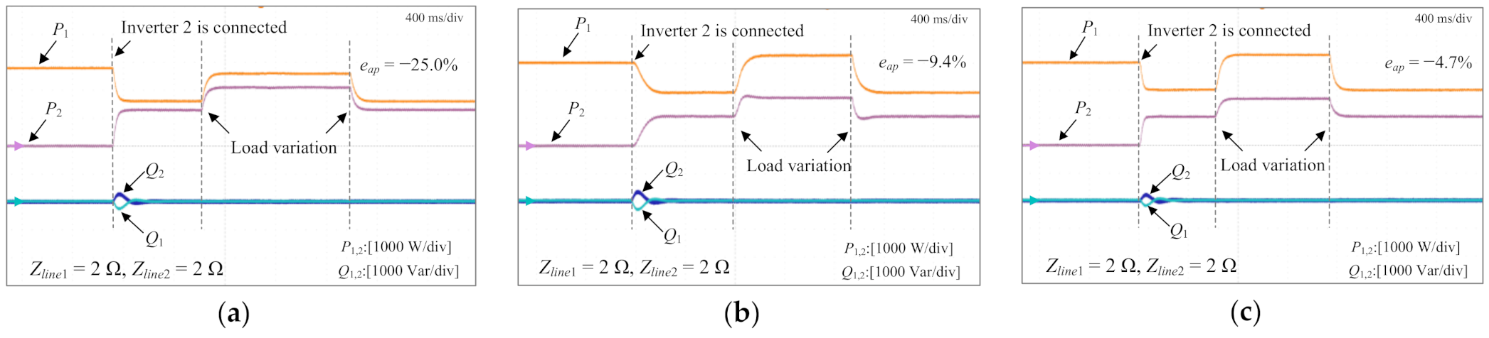
| Test Conditions | Conventional Droop Control Method [11] | PI-based Droop Control Method [15] | Proposed TSMC-based Droop Control Method |
|---|---|---|---|
| Power allocation error (eap) (Case I) | −23.5% | −5.3% | 0.6% |
| Power allocation error (eap) (Case II) | −43.2% | −6.5% | 1.3% |
| Power allocation error (eap) (Case III) | −25.0% | −9.4% | −4.7% |
| PCC voltage deviation rate | −0.93%/−2.86% | 0.61%/0.19% | 0.16%/−0.06% |
| PCC voltage variation rate | −1.95% | −0.42% | −0.23% |
Publisher’s Note: MDPI stays neutral with regard to jurisdictional claims in published maps and institutional affiliations. |
© 2021 by the authors. Licensee MDPI, Basel, Switzerland. This article is an open access article distributed under the terms and conditions of the Creative Commons Attribution (CC BY) license (http://creativecommons.org/licenses/by/4.0/).
Share and Cite
Zhang, Q.-Q.; Wai, R.-J. Robust Power Sharing and Voltage Stabilization Control Structure via Sliding-Mode Technique in Islanded Micro-Grid. Energies 2021, 14, 883. https://doi.org/10.3390/en14040883
Zhang Q-Q, Wai R-J. Robust Power Sharing and Voltage Stabilization Control Structure via Sliding-Mode Technique in Islanded Micro-Grid. Energies. 2021; 14(4):883. https://doi.org/10.3390/en14040883
Chicago/Turabian StyleZhang, Quan-Quan, and Rong-Jong Wai. 2021. "Robust Power Sharing and Voltage Stabilization Control Structure via Sliding-Mode Technique in Islanded Micro-Grid" Energies 14, no. 4: 883. https://doi.org/10.3390/en14040883
APA StyleZhang, Q.-Q., & Wai, R.-J. (2021). Robust Power Sharing and Voltage Stabilization Control Structure via Sliding-Mode Technique in Islanded Micro-Grid. Energies, 14(4), 883. https://doi.org/10.3390/en14040883