Article

Application-Oriented Reactive Power Management in German Distribution Systems Using Decentralized Energy Resources

1
Division Grid Planning and Grid Operation, Fraunhofer Institute for Energy Economics and Energy System Technology, Koenigstor 59, 34119 Kassel, Germany
2
Bayernwerk Netz GmbH, Lilienthalstraße 7, 93049 Regensburg, Germany
3
Department of Energy Management and Power System Operation, University of Kassel, Wilhelmshoeher Allee 73, 34121 Kassel, Germany
*
Author to whom correspondence should be addressed.
Energies 2021, 14(16), 4949; https://doi.org/10.3390/en14164949
Submission received: 19 July 2021 / Revised: 4 August 2021 / Accepted: 9 August 2021 / Published: 12 August 2021
(This article belongs to the Special Issue Optimal Control of Smart Distributed Power and Energy Systems)

Abstract

:
Due to higher penetration of renewable energy sources, grid reinforcements, and the utilization of local voltage control strategies, a significant change in the reactive power behavior as well as an increased demand for additional reactive power flexibility in the German power system can be predicted. In this paper, an application-oriented reactive power management concept is proposed, which allows distribution system operators (DSO) to enable a certain amount of reactive power flexibility at the grid interfaces while supporting voltage imitations in the grid. To evaluate its feasibility, the proposed concept is applied for real medium voltage grids in the south of Germany and is investigated comprehensively in different case studies. The results prove the feasibility and reliability of the proposed concept, which allows the DSO to control the reactive power exchange at grid interfaces without causing undesired local voltage problems. In addition, it can be simply adjusted and widely applied in real distribution grids without requiring high investment costs for complex information and communication infrastructures. As a significant contribution, this study provides an ideal bridging solution for DSOs who are facing reactive power issues but have no detailed and advanced monitoring system for their grid. Moreover, the comprehensive investigations in this study are performed in close cooperation with a German DSO, based on a detailed grid model and real measurement data.

1. Introduction

In Germany, the key policy of “Energiewende” [1] (German for energy system transformation) results in a huge expansion of renewable energy sources (RES) in German distribution grids [2]. In 2019, renewable energy sources covered about 43% of the net electricity consumption in Germany according to Wirth in [3], with about 49 GW total installed capacity from 1.7 Million PV systems according to the German Solar Industry Association [4] and about 61 GW from Wind (onshore and offshore) [5]. Due to higher penetration of renewable energy sources, the required grid reinforcements, and the utilization of different local voltage control strategies, a significant change in the reactive power (Q) behavior as well as an increased demand for additional reactive power flexibility in the German power system can be predicted [6,7]. According to current German grid codes [8,9,10], decentralized energy resources (DER) such as wind and large-scale photovoltaic (PV) plants connected to the German power system should have the capability to provide controllable reactive power at their feed-in times. Currently, the reactive power provision from DERs within the predefined Q range according to the relevant guidelines is free of charge [11]. German DSOs are therefore looking for appropriate reactive power management approaches, with the goal of providing additional ancillary services such as voltage control, reactive power compensation, and supporting reactive power balancing at grid interfaces. The implementation of the reactive power control using DERs, however, varies highly between different DSOs. Until now, various Q control management and control strategies are introduced.
For instance, local Q control strategies have been comprehensively investigated in several research studies (e.g., [12,13,14,15]) and are currently applied in some German distribution grids. The local Q control approach is generally based on local droop curves and does not require communication between local controllers and the distribution management system (DMS). Since measurements are only recorded, processed, and interpreted by the local DER controller itself, this type of Q control reacts extremely fast and requires no detailed knowledge from networks. There are different possibilities to implement such a local Q control. Nowadays, typical local Q controls in Germany are the so-called Fixed c o s φ , the c o s φ (P), and the Q(V) control, which are mostly used to support local voltage regulation [16]. In recent years, different central Q management and optimization approaches have been introduced and investigated in several studies. For instance, in [17,18,19,20,21,22], different central Q management concepts based on the particle swarm optimization (PSO) algorithm are introduced, mainly supporting the voltage regulation in distribution grids. In other studies of S. Wende v. Berg, J. Buhr, and E. Kaempf [23,24,25], central Q management concepts using optimal power flow (OPF) are introduced, which enable a multi-voltage-level reactive power optimization (e.g., optimizing Q exchange at grid interfaces) and allow the DSO to minimize grid losses in distribution grids. In [26], a multi-objective reactive power optimization concept is introduced, considering the cost of reactive power ancillary services in the electricity market.
Nowadays, due to the increased penetration of DERs and the lack of conventional reactive power sources (e.g., large power plants), together with more stringent requirements on Q behavior from grid operators, reactive power optimization at grid interfaces between different voltage levels (e.g., at transmission/distribution interfaces) becomes an important research focus. For example, in the studies of D.S. Stock [27,28], coordinated Q management using OPF considering cooperation between transmission system operators (TSO) and DSOs is introduced and investigated for a selected high voltage (HV) grid in Germany. The proposed Q management concept performs OPF at both distribution and transmission levels and enables the DSO to fulfill individual voltage targets over multiple interfaces. Moreover, reactive power management and optimization at grid interfaces are also investigated by S. Ali from the UK [29], M. Kaspirek from the Czech Republic [30] and Y. Liu and Z. Fan from China [31,32], as the Q control and optimization is not only a challenge in German power systems but also an essential research topic worldwide. As can be seen in the proposed studies above, based on the applied optimization algorithm at DMS, the central Q management concept enables DSOs to find the global optimum of their own grids and allows the DSOs to have the flexibility for providing additional ancillary services (e.g., voltage regulation, grid losses minimization, or improvement of Q balancing issues). However, compared to local Q controls, a central Q management concept requires more detailed knowledge from the whole network. Due to the need for complex communication systems, the central Q management concept usually requires additional operational costs. Moreover, high investment for the required information and communication technology (ICT) can hardly be avoided. Hence, for those DSOs who have no detailed overview of their own system but only limited online information from the DERs (e.g., at medium voltage or low voltage grids), an appropriate Q management concept is urgently needed. The Q management concept should be application-oriented, feasible, and reliable and can simply be applied in reality without requiring detailed knowledge from networks as well as complex information and communication infrastructures.
By this definition, a combined central/local Q control strategy with a hierarchical structure enables an individual rapid local control for all the involved DERs with different objectives and parameter settings. Optionally, DSOs can also change the parameter settings of each DER sub-controller to provide additional ancillary services. For instance, a coordinated reactive power control concept is introduced in [33], which is based on centralized Q management and coordination of local voltage-dependent Q characteristics. The concept is investigated by applying it in a small benchmark network with two PV systems using “DIgSILENT PowerFactory”. Like [33], a large proportion of the existing studies so far regarding Q management and control contains only case studies with benchmark networks or generic networks. To analyze the feasibility as well as the performance of a Q management concept more comprehensively, it is important and highly recommended to perform simulations for a real distribution grid with a detailed grid model and real measurement data.
In this paper, an application-oriented Q management concept is introduced, which can be categorized as a combined central/local Q control approach. Similar to the reviewed approaches above, the proposed Q management concept in this paper also allows the DSO to enable relevant reactive power flexibility at the grid interfaces while supporting local voltage limitations. However, in comparison to the introduced works beforehand, a key benefit of the introduced concept is that it has a low requirement for online measurements. It serves hence as a bridging solution for DSOs without detailed grid monitoring until wide observability and controllability is realized in the future. Moreover, since it applies a characteristic-based algorithm (without global optimization), the proposed concept shows a speedy response and a simple implementation, even for a large distribution system with a large number of controlled DERs. As another significant contribution of this study, the proposed Q management concept is investigated in close cooperation with a German DSO by performing time-series simulations for a real medium voltage (MV) grid located in the south of Germany, with a detailed multi-voltage-level grid model and real measurement data. The achieved results in this paper show that the proposed concept is a feasible and reliable approach, which can be simply and generally applied in German distribution systems without requiring complex ICT infrastructures. The approach integrates well with a standard grid planning process and planning processes for reactive power management. This paper is structured in five sections. Section 2 details the proposed application-oriented Q management concept. In Section 3, the feasibility of the proposed concept is investigated by applying it in medium voltage grids with different case studies. In Section 4, achieved results are discussed, and Section 5 gives the conclusion of this paper.

2. Methods

2.1. Objective

This study is based partly on a joint research project [34] for reactive power management in the distribution system, in cooperation with the German DSO “Bayernwerk Netz GmbH”, who provided detailed grid and measurement data as well as very helpful discussions and ideas for the underlying study. In this research project, a real medium voltage grid is selected as a case study area. Meanwhile, objective and key requirements for a new Q management concept from the DSO’s point of view are discussed and outlined. The following objectives and key requirements hence should be addressed and taken into consideration during the development and realization of reactive power management concepts:
  • Control of the reactive power exchange at the 110 kV network connection point;
  • Use of the Q provision capability from DERs in MV grids;
  • Compatibility with the local Q(V) control;
  • Operation with limited online information;
  • Simple implementation in the existing network operation system;
  • Reliable and stable operation behavior;
  • Potential of a wide application in the distribution system.
Control of the reactive power exchange at the 110 kV network connection point (NCP):
Nowadays, HV and MV grid operators usually have certain agreements on the allowed Q exchange at the interface between HV and MV grids. Applying different local control strategies such as Fixed c o s φ and c o s φ (P) control at LV and MV levels could improve the hosting capacity of the distribution grid; however, they could also increase the Q exchange at grid interface and may lead to violation of the predefined operational area. A reactive management approach should therefore enable a controlled Q exchange at grid interfaces between two voltage levels (which is the 110 kV-NCP in this study).
Use of the Q provision capability of DERs in MV grids:
According to the current technical connection guidelines in Germany, DERs connected in German distribution systems should have the capability to provide controllable reactive power at their feed-in times. The new Q management approach therefore should make use of the reactive power control capabilities of DERs at the MV level to enable a certain amount of reactive power flexibility at the 110 kV-NCP.
Compatibility with the local Q(V) control:
Since the characteristic-based local Q(V) control provides an effective contribution to voltage maintenance while avoiding unnecessarily high reactive power flows, it now becomes an important part of the technical grid connection guidelines of Bayernwerk Netz GmbH. The reactive power management concept hence should be compatible with the existing local Q(V) control.
Operation with limited online information:
Due to the large number of DERs, usually only limited online information about local DERs can be gathered from a distribution system operator. DSOs hence usually do not have a detailed overview on the current state of the entire MV or LV grids. An application-oriented Q management approach hence should be able to be applied with only limited online information from the network.
Simple implementation in the existing network operation system:
According to the requirements of DSOs, the newly developed Q management concept should be simply and rapidly implemented in the existing network operating system without requiring complex and expensive system extension.
Reliable and stable operation behavior:
Like any other control approach, the developed concept should show a reliable and stable control behavior without causing undesired problems such as:
  • — Fluctuation of reactive power exchanges;
  • — Voltage stability problem at the MV level;
  • — Undesired tap changing of transformers at substations.
Potential of a wide application in the distribution system:
The wide and general application of the developed Q management concept is an important requirement for DSOs. The application of the proposed concept should not be limited only in the selected case study in this study but should also suitable for other grids.

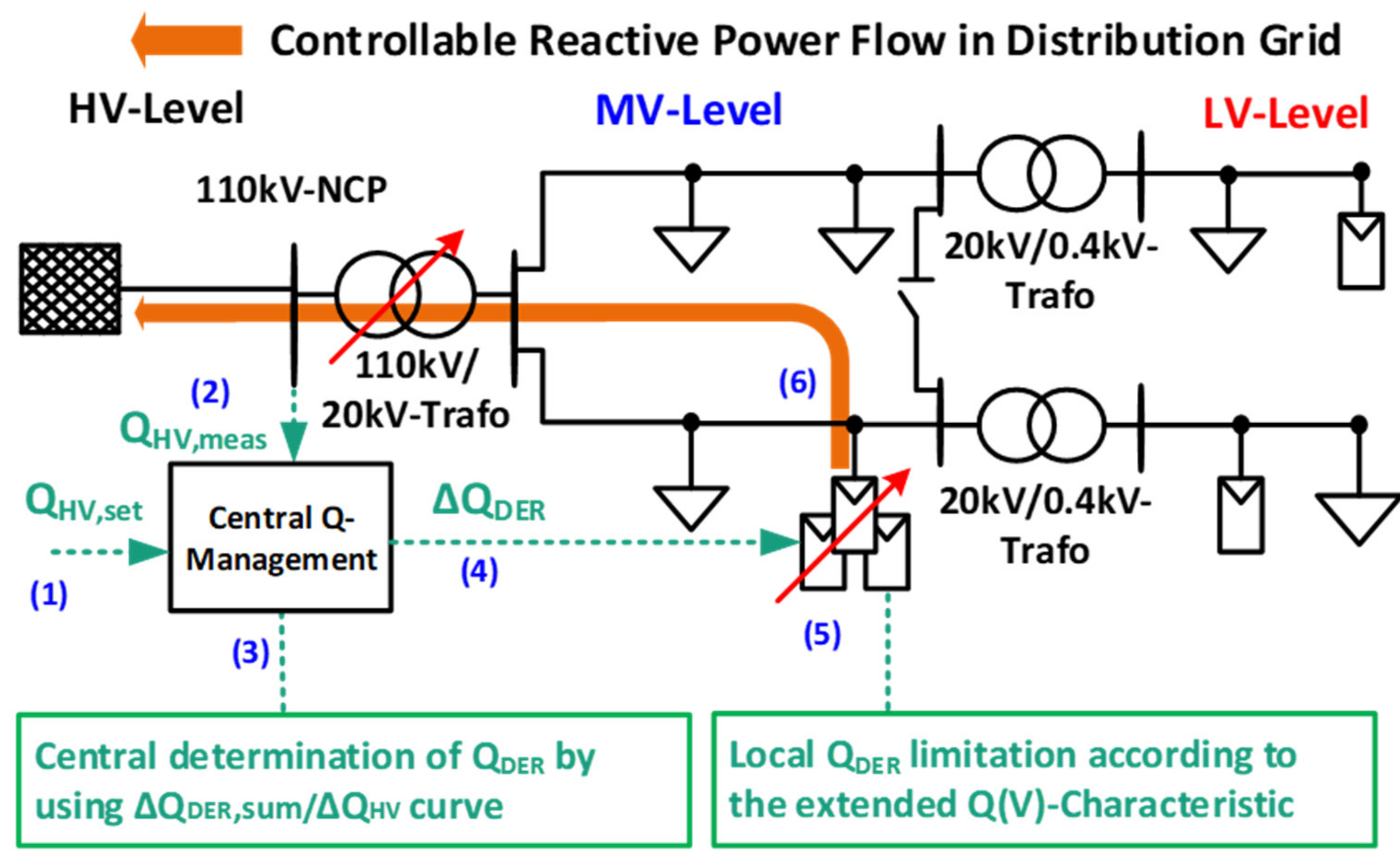
2.2. Overview of the Applied Concept

One simplification for a central Q management approach would be a copperplate approach, which assumes a quasi-linear relationship between Q provision from DERs and the induced reactive power exchange at grid interfaces to the up-streamed voltage level. Under this precondition, an application-oriented Q management concept is hence developed and investigated in this study. Figure 1 gives a general overview of the proposed Q management concept, which aims at controlling the Q exchange at the 110 kV network connection point (110 kV-NCP) using local Q provision from DERs at the MV level.
Unlike the central Q management with OPF, the proposed Q management concept in this study does not perform a global optimization and hence does not require detailed knowledge of the network. In contrast, it needs only the actual Q exchange at the 110 kV-NCP as its online measurement for DMS. Therefore, the proposed concept is especially suitable for distribution systems, where only limited online information is available. The proposed Q management concept can be mainly divided into two parts: central determination of the reactive power changes of controllable DERs Δ Q DER and local limitation of Q provision from DER Q DER . The entire Q management concept can be further described by six basic control processes in Figure 2 (control processes 1−6 are also marked accordingly in Figure 1).
Step 0 is considered as pre-analysis in this study to check the precondition of applying the proposed Q management concept on the selected case study area. Steps 1 to 4 are the central control part and can be considered as task of the DMS. In contrast, steps 5 and 6 are considered as the local control part and should be locally implemented in the DER controllers. A detailed description of each control process and the associated equations are given as follows.

2.3. Check Precondition (Static Pre-Analysis)

(0) Perform sensitivity analysis for the investigated case study area:
Since the proposed Q management approach is based mainly on the quasi-linear relationship between Q provision from DERs and the induced Q changes at the grid interface, a pre-analysis should be performed for the selected case study area at first. The pre-analysis aims to investigate the sensitivity between Q provision from DERs and the induced Q changes at the grid interface (110 kV-NCP) and to confirm the so-called quasi-linear relationship. In this study, this pre-condition is investigated by performing sensitivity analyses for different PV units in the selected MV grid. During this sensitivity analysis, a certain amount of Q provision from a selected PV unit i ( d Q PVi ) is fed into the MV grid. The ratio between the induced Q changes at the 110 kV-NCP ( d Q NCP ) and the Q provision from PV i ( d Q PVi ) is defined as a sensitivity factor:
f Q PVi = d Q NCP / d Q PVi
At the next step, the Q provision from the PV i is increased and changed with a small step (e.g., 0.1 Mvar). For each step j , a sensitivity factor f Q PVi , j is determined for the PV i . The mean values of the sensitivity factors with different Q provision from PV i are then determined and saved in a so-called sensitivity matrix.
f Q mean , i = 1 n × j = 1 n f Q PVi , j
The proposed process should then be repeated for all controlled DERs in the selected case study area. In this study, the sensitivity matrix for the selected MV grid can be found in Section 3.1. As can be seen, the results of the pre-analysis confirm the assumed quasi-linear relationship ( f Q mean , i 1 ). The proposed application-oriented Q management concept therefore can be applied in the selected case study area.

2.4. Central Q Control (Online Grid Operation)

(1)
Determine the target value of Q exchange at 110 kV-NCP:
At the first stage, the HV grid operator defines their request on the Q exchange at the 110 kV-NCP (grid interface between HV and MV levels). It can be predefined by a grid planning process and defined by a global V-Q optimization process or present demands. The request on Q exchange can be given in form of individual setpoints or by specifying reactive power bands.
(2)
Determine the current deviation of Q exchange at 110 kV-NCP:
Based on the target value of Q exchange Q HV , set and the present reactive power flow measured at 110 kV-NCP Q HV , meas , the central control system determines the current reactive power deviation at the 110 kV-NCP Δ Q HV .
(3)
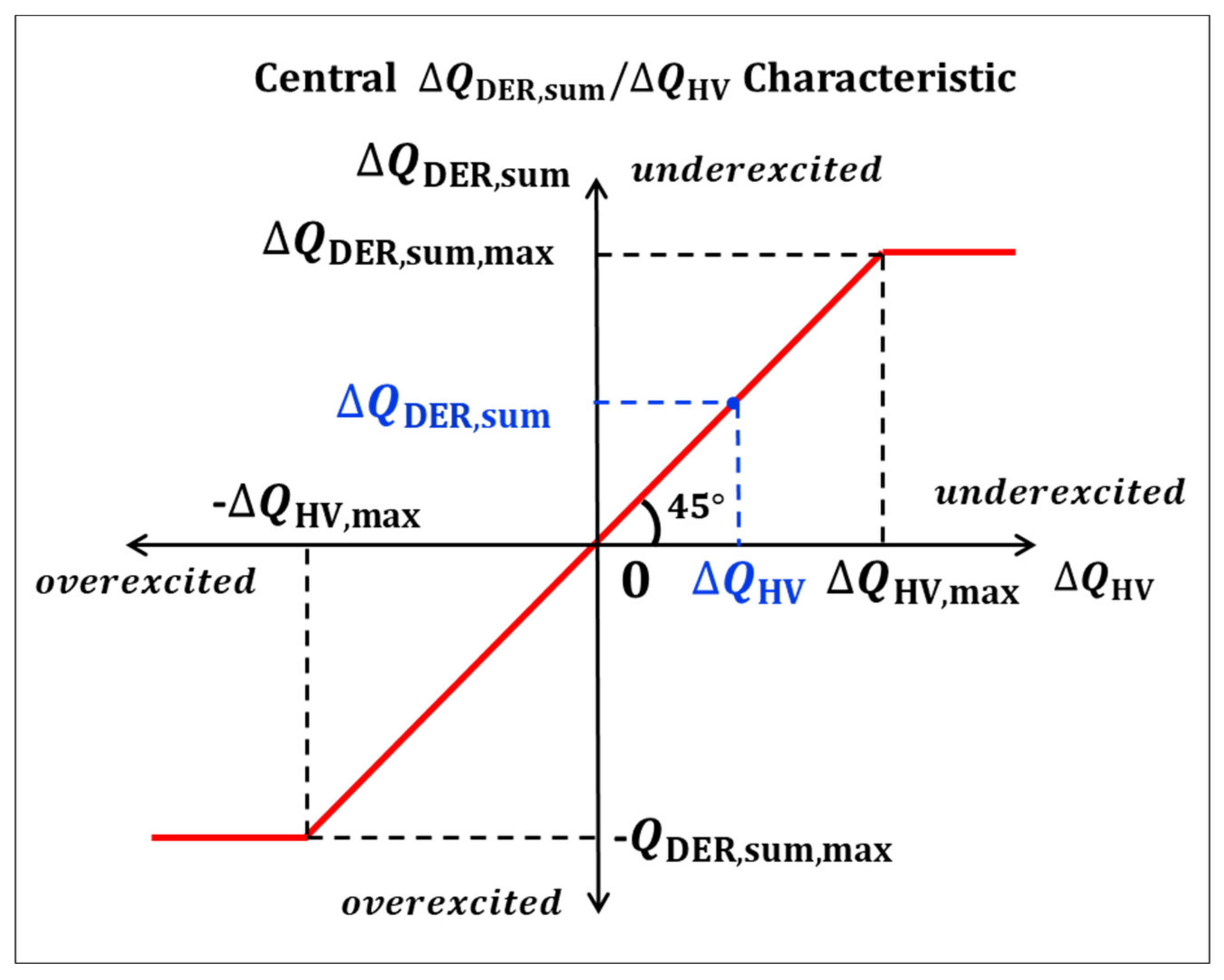
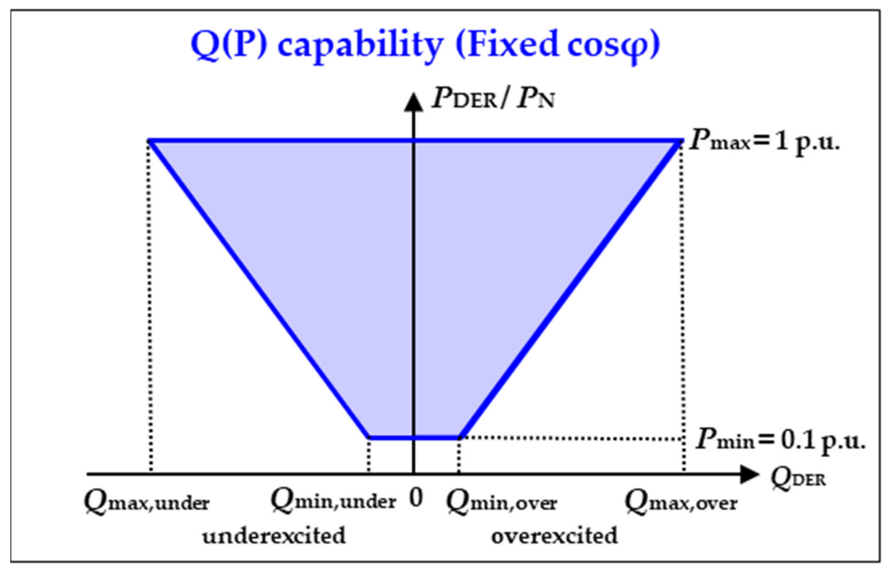
Determine the Q setpoint deviation for all controllable MV DERs:
After the MV control system determines the reactive power setpoint deviation Δ Q HV , the changes in reactive power provisions from all controlled DERs at the MV level are calculated by using a central Δ Q DER , sum / Δ Q HV characteristic curve shown in Figure 3, which assumes a quasi-linear relationship between the total Q provision from DERs and the induced Q change at 110 kV-NCP.
Δ Q DER , max = S install , i   · sin a r c c o s c o s φ min
Δ Q DER , max = i = 1 n Δ Q DER , max
Δ Q HV Δ Q DER , sum = Δ Q HV , max Δ Q DER , max = 1
Δ Q DER , sum = Δ Q HV
where:
  • Δ Q DER , max is the maximum Q change/provision of the DER I;
  • S install , i is the installed power of the DER I;
  • c o s φ min is the minimum power factor (e.g., c o s φ min = 0.95 );
  • Δ Q HV , max is the maximum Q-change at the 110 kV-NCP caused by the Q provision from all controllable DERs;
  • Δ Q HV is the setpoint deviation of the Q exchange at the 110 kV-NCP;
  • Δ Q DER , sum is the sum of the reactive power change of controllable MV DERs;
  • Δ Q DER , max is the sum of the maximum Q provision of controllable MV DERs.
Since the exact location of MV DERs has only a very limited effect on this quasi-linear relationship, the entire required DER Q provision can be simply distributed to individual MV DERs proportionally according to their installed capacities. The Q change of each DER can be then calculated using the following equation:
Δ Q DER , i = Δ Q DER , sum · S install , i S i nstall , sum
where:
  • Δ Q DER , i is the additional required reactive power provision from the DER i;
  • Δ Q DER , sum is the sum of required reactive power provision from all controlled DERs;
  • S install , i is the installed power of the DER i;
  • S install , sum is the sum of the installed capacity of all controlled DERs.
(4)
Send the Q setpoint change to the DER Controller:
The determined change of the Q provision Δ Q DER , i can be then transmitted using the existing ICT infrastructure to all DERs at the MV level, which are controllable and involved in the Q management.

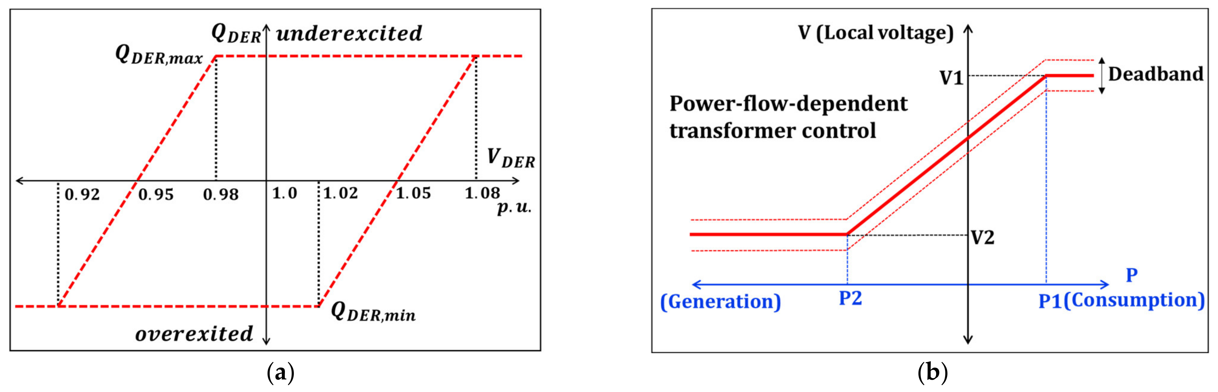
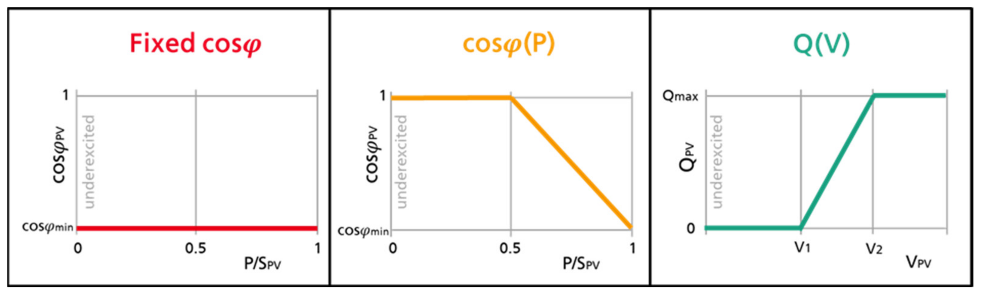
2.5. Local Q Control (Online DER Operation)

(1)
Local limitation according to the extended Q(V)-characteristic:
After the MV DERs receive their reactive power provision changes Δ Q DER , i , new target values of the local reactive power provision Q DER , new can be locally determined based on the current reactive power provision. It is assumed in this study, that the controlled DERs could provide reactive power according to a predefined minimum power factor ( c o s φ min = 0.95 in this study, Figure 4). Therefore, the local DER controller then checks if the new target values exceed the predefined minimum power factor. Moreover, it is also assumed in this study that the DERs have no Q provision capability in times with very low active power feed-in (<10% of P N ). It is important to mention that the applied Q(P) provision capability is only assumed for this study. The DER Q(P) provision capability, however, may differ a lot from the connected voltage level, the applied inverter technology (e.g., Q provision with STATCOM or so-called Q@Night capability) as well as different DER types.
Q DER , new = Q DER , now + Δ Q DER , i
Q DER , new   P DER , now · tan arccos c o s φ min
Q DER , i , new = 0 ,   if   P DER , now P N < 0.1
where:
  • Q DER , i , new is the new reactive power setpoint of DER i;
  • Q DER , now is the current reactive power provision of DER i;
  • Δ Q DER , i is the determined reactive power provision change of DER i;
  • P DER , now is the current active power feed-in of DER i;
  • P N is the nominal power of DER i;
  • c o s φ min is the minimum power factor of DER i ( c o s φ min = 0.95 in this study).
After the new Q setpoint is determined, the local DER controller then checks the calculated setpoint according to a so-called extended Q(V) limitation characteristic (Figure 5) and limits the operating point of DER within the predefined operational area if the new Q setpoint lies outside this area. The applied Q(V) characteristic defines the operational area that can be used for reactive power management, depending on the local grid voltage at the point of common coupling (PCC) of the DER.
Applying this local Q limitation process could enable, on the one hand, a certain amount of controlled reactive power flexibility at 110 kV-NCP and supports, on the other hand, the local voltage limitation by avoiding undesired local Q provision from DER. The idea of using such a Q(V) limitation characteristic is firstly introduced and discussed in a previous study of SMA Solar Technology AG together with “Bayernwerk Netz GmbH” [35] and is further adjusted and applied in this study. Nowadays, the Q(V) limitation characteristic is also part of the German grid codes, which specifies the Q provision capability of DER connected to MV level of the German distribution system [9].
(2)
Set the Q provision of controllable MV DERs:
Finally, the DER sets their actual reactive power provision according to the new setpoint Q DER , which is determined in the control process 5. Furthermore, to ensure the control and system stability, it is suggested to add a PT1 element with a suitable time constant (e.g., with 5 s) to the local DER controller or PV inverter [36,37]. Since the Q exchange at 110 kV-NCP varies strongly with load and generation variations, the whole control process 1–6 hence is suggested to be continuously repeated after a certain control interval given by the DSO (e.g., 1 min, 5 min).

3. Case Studies and Results

In this section, the application-oriented Q management concept is implemented and investigated with grid model and measurement data of the real MV smart grid Seebach of the German DSO Bayernwerk Netz GmbH, located in the south of Germany. As case studies, the reactive power exchange at 110 kV-NCP is controlled to meet different Q setpoints. Additionally, cooperation between the proposed Q management concept and different local voltage control strategies are also investigated. This section aims to investigate the feasibility as well as the technical potential of the proposed Q management concept.

3.1. Applied Simulation Environment

The selected smart grid Seebach covers the HV/MV (110/20 kV), MV (20 kV), MV/LV (20/0.4 kV), and LV (0.4 kV) levels. It has one network connection point at the 110 kV level. The grid is characterized by a very high distributed PV penetration. In the selected grid region, 15 large PV systems with a total installed capacity of approx. 10.7 MVA are distributed and connected to 12 points of common coupling at the MV level (Figure 6). These 15 large MV PV systems are considered in this study as controllable DERs and are controlled by the proposed Q management concept. Moreover, about 1500 small PV units are installed at the LV level with a total installed capacity of about 30.4 MVA. In this section, a multi-voltage-level grid model of the grid Seebach was developed by using the simulation tool “pandapower” [38,39], whereby the MV and LV levels are fully modeled in detail. Figure 6 illustrates the grid topology of the selected case study area Seebach.
In order to check the precondition and to investigate the influence of Q provision from DERs on the Q exchange at 110 kV-NCP, sensitivity analyses for different PV units in MV grid Seebach and for two use cases are performed (use case 1: no PV generation, high load consumption, use case 2: high PV generation, low load consumption). During this sensitivity analysis, a Q provision of −1 Mvar (overexcited) from a selected PV unit i ( d Q PVi ) is fed into the MV grid. The ratio between the induced Q changes at the 110 kV-NCP ( d Q NCP ) and the Q provision from PV i ( d Q PVi ) is defined as sensitivity factor f Q PVi = d Q NCP / d Q PVi . At the next step, the Q provision from the PV i is increased from −1 Mvar (overexcited) to 1 Mvar (underexcited) with a step of 0.1 Mvar. For each step, a sensitivity factor is determined for the PV i . The proposed process is then repeated for all the 15 MV PV units in the MV grid Seebach. The mean values of the ratios ( d Q NCP / d Q PVi ) with different Q provisions are then determined and saved in a so-called sensitivity matrix. Table 1 shows the sensitivity matrix for all PV units at the MV level for Use Case 1 with “no PV generation and high load consumption” as well as for Use Case 2 with “high PV generation and low load consumption”.
The sensitivity matrix in Table 1 shows a quasi-linear relationship between the Q provision from MV PV units and the induced Q changes at the 110 kV-NCP. By this definition, the additional provided Q from PV units can also be expected and observed at the grid interface. However, due to the changed Q flow in the distribution grid and the induced changes of grid components loading (e.g., the HV/MV transformer), the selected grid also shows a minimal change of its own reactive power consumption. For this reason, the relationship between Q from DER and the induced Q changes at the grid interface is only quasi-linear, with minor Q deviation. For instance, if a reactive power of 1 Mvar (underexcited) is provided from PV 1, a Q change of approximately 1.012 Mvar at the 110 kV-NCP can be expected in Use Case 1 with no PV generation and high load consumption. By comparing the sensitivity factors for different PV units and different use cases, it can be seen that the location of PV units, as well as the selected use cases, have only minor influences on the assumed quasi-linear relationship. The precondition for applying the introduced application-oriented Q management concept in the selected MV grid Seebach is therefore confirmed.
In this study, time series simulations are then performed for two types of days: a sunny summer day with clear skies as well as a cloudy summer day with highly intermittent solar irradiation, so that the performance and feasibility of the proposed Q management concept can be tested for both situations. The applied PV generation profiles are derived based on generation profiles and the real historical measurements at 110 kV-NCP. The goal of the applied simulation environment is to investigate the feasibility of the proposed Q management concept with different case studies in a more realistic condition using a real distribution grid model and measurement data, profiles for generators, and loads. During this investigation, all 15 large MV PV units in the case study area Seebach are centrally controlled by the proposed application-oriented Q management concept. Based on a joint discussion with the German DSO, the local Q(V) limitation curve in Figure 7a is applied for all PV units. Voltage limitation at the MV level hence is considered as a boundary and can be possibly supported. Additionally, a power-flow-dependent transformer control approach is applied for the HV/MV transformer at 110 kV-NCP. The applied transformer control approach is based on a so-called V(P) characteristic (Figure 7b) with active power dependent voltage setpoints [40], which is usually applied with a suitable deadband (e.g., ±0.01 p.u. in this study) in reality. Using this type of transformer control could sufficiently support the voltage limitation, especially in times with high DER feed-in and times with reversed active power flow.

3.2. Case Studies in MV Grid Seebach

In this section, different case studies are defined and investigated. In case study 1, the proposed Q management concept is applied at the MV level to minimize the Q exchange at 110 kV-NCP. In case study 2, it is assumed that the HV grid operator may request different Q setpoints at the grid interface. The proposed concept is thus applied to meet different requested values for Q provision at the grid interface. In case study 3, different local voltage control approaches are applied for PV units at the LV level. The parallel operation of the proposed Q management concept at the MV level and different local voltage controls at the LV level are investigated.

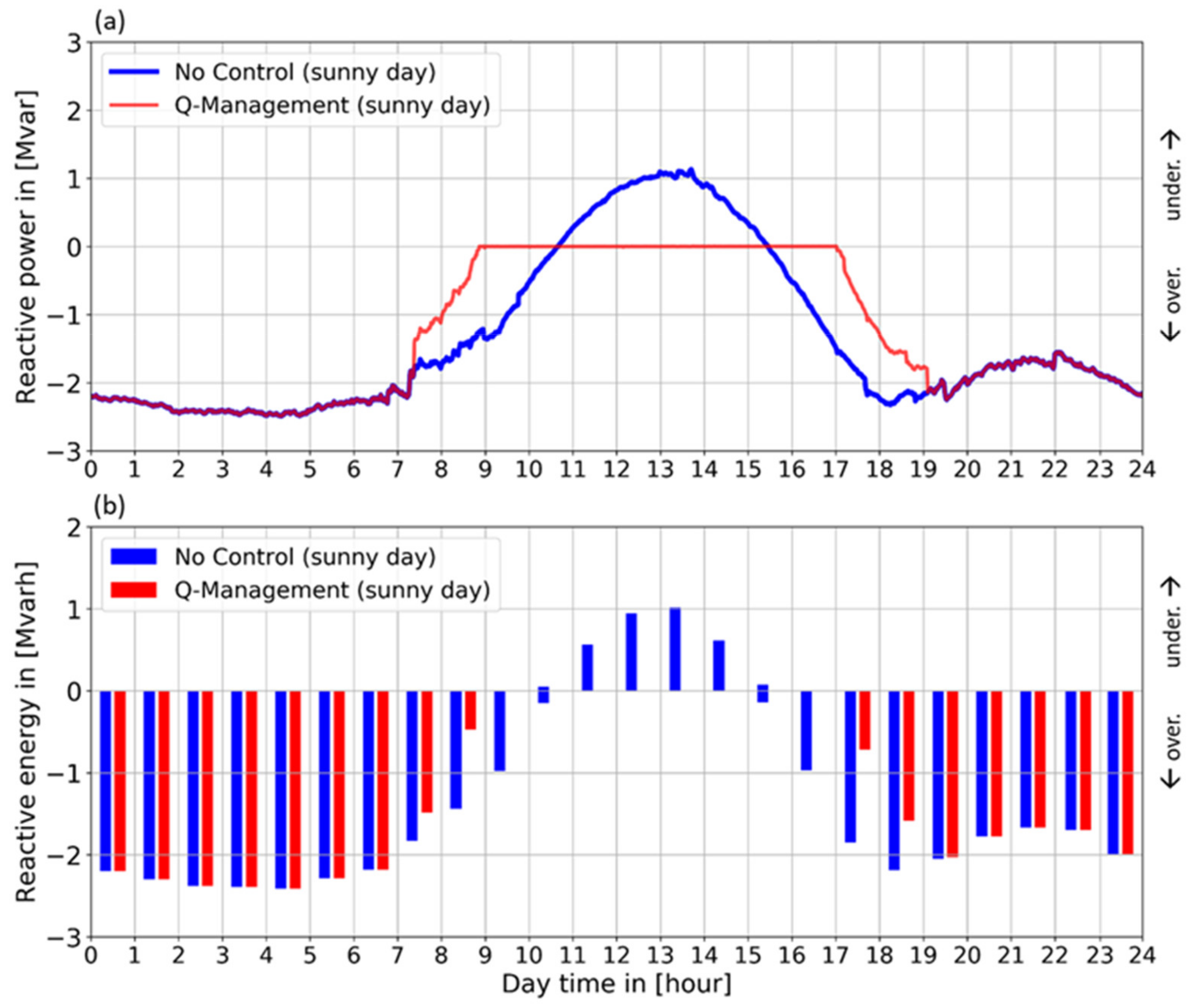
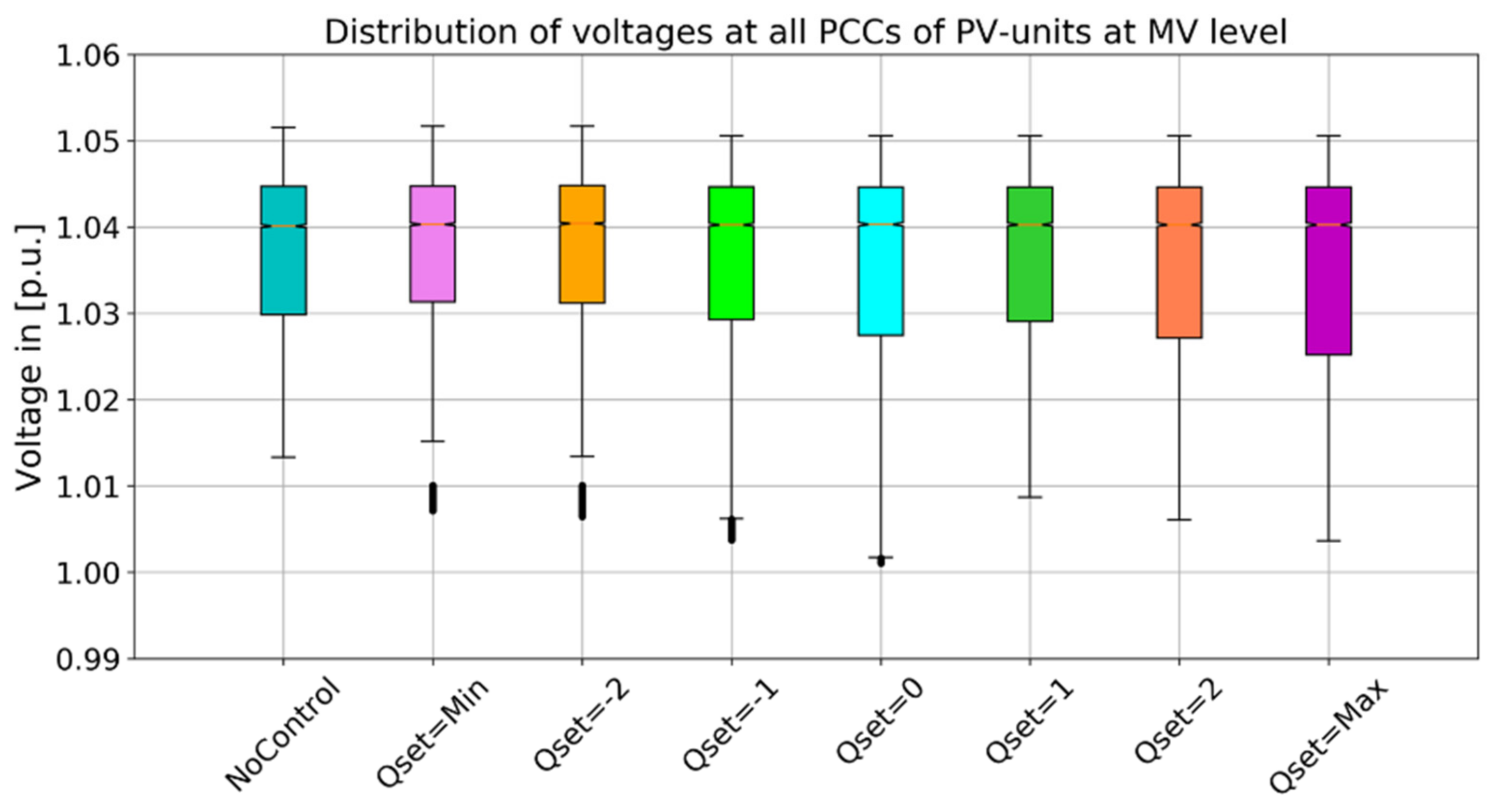
3.2.1. Case Study 1: Minimization of Reactive Power Exchange at 110 kV-NCP

As the control objective in case study 1, it is assumed that neither inductive nor capacitive Q exchanges at 110 kV-NCP are desired. The Q exchange should therefore be fully compensated by using the proposed Q management approach (setpoint of Q exchange at 110 kV-NCP is set to 0 ). Based on the developed simulation environment, daily simulations are then performed for the selected sunny day and cloudy day with a 1-min control interval. Figure 8 shows the Q exchange at 110 kV-NCP for each time step within the investigated sunny day (top). The blue line represents the original Q exchange without control. The red line shows the controlled Q exchange by applying the proposed Q management approach.
It can be seen that due to the increased PV generation, Q consumption of consumers, and loading of grid components (e.g., transformer and cable), the Q exchange at 110 kV-NCP changes continuously during the investigated sunny day (blue line). Using the Q management approach could significantly minimize the reactive power exchange (red line). Especially in times with high PV generation and high Q provision potential (e.g., 9:00 to 17:00), almost full compensation of Q exchanges at 110 kV-NCP can be observed. Moreover, even the relationship between the Q provision from PV and the induced Q changes at 110 kV-NCP are greatly simplified, no significant control deviation is observed in the times with enough DER Q provision potential. Hence, satisfactory control accuracy can be achieved for the sunny day with low PV variability and low variability of the Q exchange at the HV/MV grid interface. Furthermore, Figure 8 below also shows the resulting reactive energy exchange at 110 kV-NCP (in Mvarh). It can be seen that applying the proposed control approach could achieve a significant saving potential regarding the exchanged reactive energy in times with high PV feed-in. However, as for DER Q provision capability, a relatively conservative assumption with a fixed minimum power factor of 0.95 is applied for the controlled PV units in MV grid Seebach (Figure 4). For this reason, in times with only limited or no PV feed-in where the selected grid section (with a high cabling degree) usually has very low loading of grid components and shows therefore an overexcited Q exchange, limited Q saving potential is achieved. Nowadays, some PV units can also provide reactive power-in times with no PV feed-in (STATCOM functionality). With the additional STATCOM functionality for PV systems, a significant reduction of Q exchange should also be possible in times of only limited or no PV feed-in.
In this section, a times series simulation is also performed with a 1-min control interval for a cloudy summer day, which shows a highly-changing solar irradiation. In comparison to the results for the sunny day, in a case with very intermittent PV generation, the performance of the proposed Q management approach might be influenced to a certain extent. Figure 9 illustrates the reactive power exchange (top) and the resultant reactive energy exchange (bottom) at 110 kV-NCP during the investigated cloudy day.
As can be seen, due to the very changeable solar irradiation and the induced changes of PV generation, the MV grid also shows a very volatile Q exchange at 110 kV-NCP in the reference scenario, especially in times with PV generation. For instance, during the time between 9:00 and 17:00, about 0.7 Mvarh underexcited Q exchange and 5.8 Mvarh overexcited Q exchange can be observed in the reference scenario (blue bars). With the proposed Q management approach, the undesired Q exchange can be significantly reduced. However, due to the very intermittent Q exchange at 110 kV-NCP and the limited DER Q provision in times very low solar irradiation, a small control deviation can be observed, with about 0.6 Mvarh overexcited Q exchange remains to be compensated during the time between 9:00 and 17:00. For the whole investigated cloudy summer day (0:00 to 24:00), a total overexcited Q exchange of 38.6 Mvarh is identified. The Q management approach enables a reduction of overexcited Q exchange with 8.7 Mvarh during the whole day, which achieves a saving potential of about 22.5%. As mentioned before, a relatively conservative assumption is applied in this study for the DER Q provision capability. In case a STATCOM functionality is assumed for the controlled PV units, a higher Q saving potential can also be achieved during the investigated cloudy summer day.

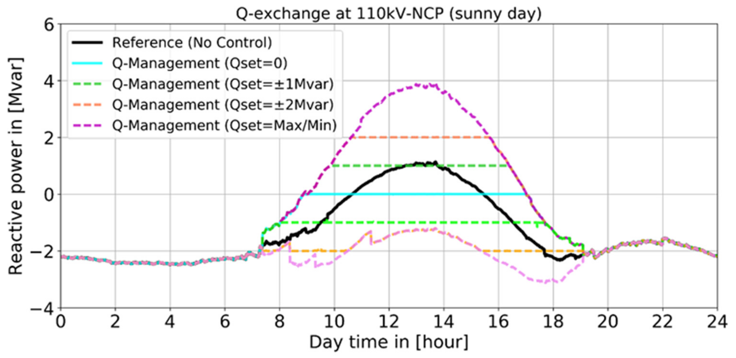
3.2.2. Case Study 2: Requested Reactive Power Provision at 110 kV-NCP

Nowadays, a controlled reactive power provision at the grid interface can be an important ancillary service provided by a DSO to the upstream grid operator. It is therefore assumed in case study 2 that the HV grid operator may request different Q setpoints at 110 kV-NCP. The Q exchange at 110 kV-NCP is hence controlled by applying the proposed Q management concept to meet different requested Q setpoints. In this case study, the following Q setpoints are considered and investigated during the sunny summer day:
  • Q s e t = 0 (Minimization, case study 1);
  • Q s e t = 1 Mvar (underexcited);
  • Q s e t = −1 Mvar (overexcited);
  • Q s e t = 2 Mvar (underexcited);
  • Q s e t = −2 Mvar (overexcited);
  • Q s e t = maximum (maximum underexcited Q provision at 110 kV-NCP);
  • Q s e t = minimum (maximum overexcited Q provision at 110 kV-NCP).
Based on the developed simulation environment, several daily simulations are performed for the sunny day with a 1-min control interval. As DER provision capability, the Q(P) characteristic with a fixed minimum power factor of 0.95 (Figure 4) is also applied for case study 2. Figure 10 gives then an overview of the controlled Q exchange at 110 kV-NCP, with different requested Q setpoints from the HV grid operator. It can be seen in Figure 10 that in times with enough Q provision potential from controlled PV-units, the requested Q setpoints can be fulfilled. However, with the assumed Q setpoint of −2 Mvar (overexcited), the requested Q exchange cannot always be fulfilled due to limited overexcited Q provision from the DER and high local voltages at the PCC of the DER. By comparing the maximum and minimum Q exchange at about 1:00 p.m., it can also be seen that in times with very high PV feed-in, a relevant Q provision potential at 110 kV-NCP from −1.2 Mvar (overexcited) to about 4 Mvar (underexcited) can be provided by the MV grid operator using the proposed Q management concept.
In addition, Figure 11 shows the distribution of voltages at the PCC of the DER in boxplots for all investigated scenarios with different Q setpoints at 110 kV-NCP. It can be seen that the voltages at the PCC of a controlled DER are mostly within a range between 1.0 p.u. and 1.05 p.u. Even under both extreme conditions (maximum over- and underexcited Q exchange at 110 kV-NCP), no critical voltage values at PCC are observed according to the achieved results. The proposed Q management concept, as a combination of central and local controls, hence could enable a relevant reactive power flexibility at grid interface while ensuring to operate within a predefined voltage band by preventing voltage problems due to undesired Q provision from DERs in the distribution system.

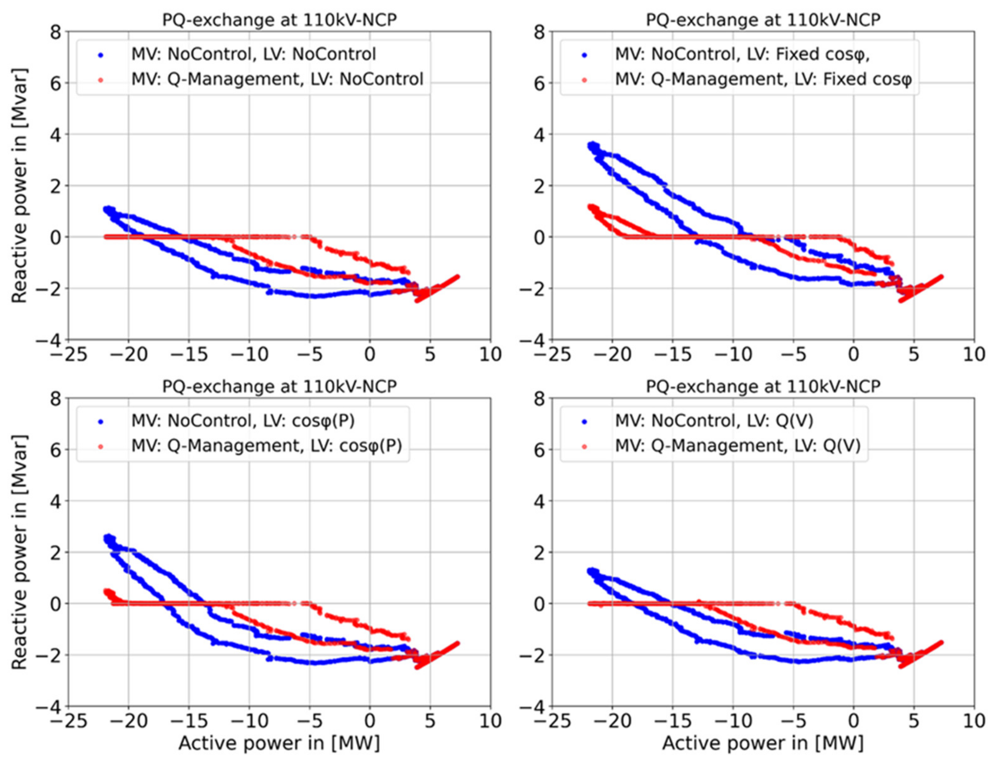
3.2.3. Case Study 3: Parallel Operation with Local Voltage Controls at LV Level

Different local voltage control strategies are requested by grid codes in Germany and many other countries. Results of several previous studies [41,42,43] show that applying these local voltage control strategies can efficiently support the local voltage limitation. However, these local voltage control strategies may also significantly affect the reactive power flow in the distribution grid as well as the Q exchange at the grid interface. For instance, in a previous study [44], the influences of different local voltage control strategies on the reactive power exchange at grid interfaces are investigated in detail. It can be seen that a wide application of local voltage control approaches may lead to a significant increase in the Q exchange at grid interfaces and hence may lead to increased Q compensation demand in distribution grids.
An alternative solution, instead of installing additional compensation devices, would be the application of the proposed Q management concept for compensating undesired reactive power flows at 110 kV-NCP. In this case study, the parallel operation of the proposed Q management approach and different local voltage control strategies are investigated in detail. The investigation is carried out for the sunny day using the introduced multi-voltage-level grid model. In this investigation, 25% of the PV units at the LV level (25% considering the total installed PV capacity at the LV level) are randomly selected. As an applied assumption, the selected LV PV units are controlled by different local voltage control strategies (Fixed c o s φ , c o s φ (P), and Q(V), Figure 12 and Table 2) while the introduced Q control approach is implemented for large PV systems at the MV level. As the control objective, the Q exchange at 110 kV-NCP should be fully compensated (minimization of Q exchange).
To demonstrate the result, Figure 13 shows the influence of the proposed Q management on the P and Q exchange at 110 kV-NCP for the investigated clear sky, sunny summer day, considering different local voltage control strategies at the LV level. It can be seen that the application of both local voltage controls (Fixed c o s φ and the c o s φ (P)) for the LV PV systems may significantly increase the underexcited Q exchange at the 110 kV-NCP (blue dots). In comparison, the local Q(V) control has only a small influence on it. By using the proposed Q management at the MV level, both the underexcited and the overexcited reactive power exchange at 110 kV-NCP can be significantly reduced in all four investigated scenarios (red dots).
This effect is particularly obvious in both scenarios with no control and Q(V) for LV PV units, in which a full compensation of the Q exchange at 110 kV-NCP can be observed in times with high PV feed-in and reverse power flow power (−5 MW to −22 MW). In both scenarios with Fixed c o s φ and c o s φ (P) at the LV level, a full Q compensation at 110 kV-NCP cannot always be achieved due to the substantial impacts of both local voltage control strategies at the LV level. Nevertheless, the proposed Q management concept enables a significant Q saving potential at the grid interface. In general, no critical interactions between the proposed Q management at the MV level and different local voltage control approaches at the LV level are observed in case study 3.

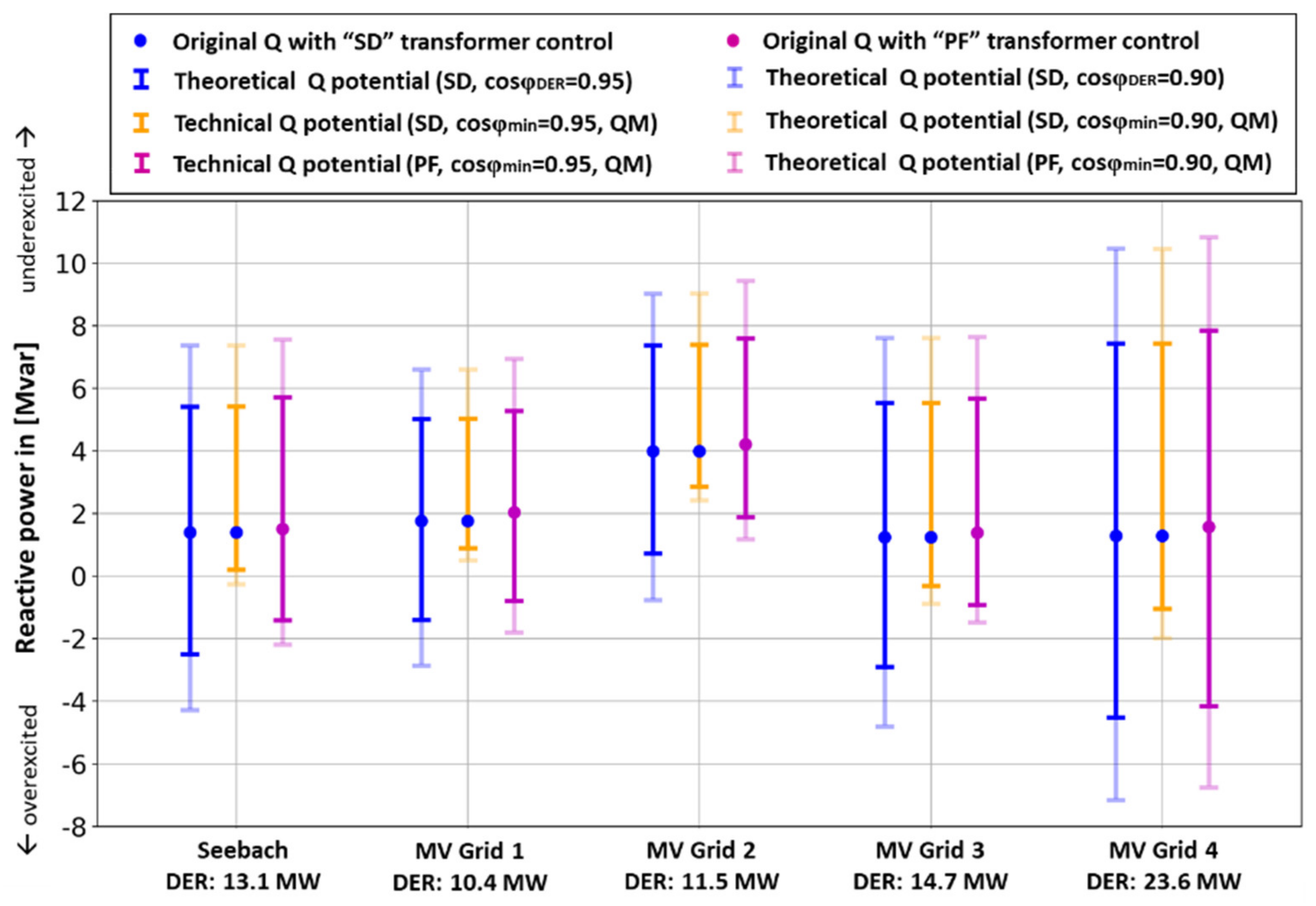
3.3. Application of Proposed Concept in Other MV Grids

In this subsection, the feasibility of the proposed concept is further investigated and tested by applying it in the selected MV grid Seebach and four other exemplary MV grids of “Bayernwerk Netz GmbH”. In this investigation, the theoretical and technical reactive power provision potential at 110 kV-NCP is determined, particularly for a single time point with high DER generation (high Q provision capability from DER) and low load consumption.

3.3.1. Definition and Methodology

Theoretical potential: The theoretical Q provision potential is defined as the maximum under- and overexcited Q exchange at 110 kV-NCP by merely setting the power factor of all MV DERs in the selected MV grid to fixed values (e.g., 0.95 or 0.9). Grid constraints such as local voltage limitations are not considered. Besides, only a standard transformer control approach with a fixed voltage setpoint is considered during the determination of theoretical potential.
Technical potential: The technical Q provision potential is defined as the maximum under- and overexcited Q exchange at the 110 kV-NCP by using the proposed Q management approach for all MV DERs. Since the proposed concept limits the maximum Q provision from DER according to the proposed Q(V) limitation characteristic (Figure 7a), local voltage limitation at PCCs hence is considered as a boundary and is possibly supported. Additionally, the power-flow-dependent transformer control approach with an active power-dependent voltage setpoint (V(P) characteristic) is also considered for adjusting the HV/MV transformer tap changer [40] (Figure 7b). The voltage level, therefore, can be permanently positively influenced in terms of setting the voltage to desired levels. In this subsection, both the standard transformer control with fixed a voltage setpoint (1.02 p.u.) and the power-flow-dependent transformer control are applied while estimating the technical Q provision potential.
The following scenarios in Table 3 are considered and investigated for the assessment of theoretical and technical potential. First, the theoretical Q provision potential is determined in Scenario 1 for all five selected MV grids by setting the power factor of all MV DERs to 0.95 or 0.9. The technical Q provision potential using the proposed Q management is then determined in Scenario 2. Two minimum c o s φ are considered for the MV DERs (0.95 or 0.9). The standard transformer control is used in both Scenario 1 and Scenario 2. Additionally, the power-flow-dependent transformer control is considered and implemented in Scenario 3. The possible technical Q provision potential is then analyzed. Table 4 gives an overview of detailed information about the selected five MV grids.

3.3.2. Theoretical and Technical Potential

As for achieved results, Figure 14 illustrates the estimated theoretical potential (Scenario 1) as well as the technical potential (Scenario 2 and 3) for the five investigated MV grids. Both the theoretical and technical potentials are estimated for a case with high DER generation and low load consumption. Firstly, the original reactive power exchange at 110 kV-NCP with the standard transformer control (original Q with SD transformer control) is marked in Figure 14 by blue points, which is considered in this study as the reference point. Secondly, the blue bars show the estimated theoretical Q provision potential in Scenario 1, which is the maximum under- and overexcited Q exchange at 110 kV-NCP by merely setting the power factor c o s φ DER to fixed values (solid bar with c o s φ DER = 0.95 , transparent bar with c o s φ DER = 0.9 ). During the estimation of the theoretical potential, grid constraints such as voltage limits at the MV level are not considered.
In comparison, the yellow bars show the estimated technical Q provision potential at 110 kV-NCP by using the proposed Q management concept in scenario 2 (solid bar with c o s φ m i n = 0.95 , transparent bar with c o s φ D E R = 0.9 ). The comparison between the theoretical and technical Q provision potential shows that applying the proposed Q management enables a significant underexcited Q provision potential at 110 kV-NCP since no difference is identified between Scenario 1 and 2 regarding the maximum underexcited Q provision. However, it can also be seen that only relatively limited overexcited Q provision potential is enabled in Scenario 2. The main reason for the limitation is the relatively high local voltage at the PCC of the DER and the applied Q(V) limitation characteristic in the local DER controller. To avoid voltage violation caused by undesired Q provision, only limited overexcited Q provision of DER is allowed by the local controller, especially in the case of high DER generation and high local voltages.
In addition, Figure 14 also shows the results of applying the Q management concept together with the so-called power-flow-dependent transformer control (Scenario 3 in purple bars). It can be seen that a significant expansion of the overexcited technical Q provision potential can be achieved by using the power-flow-dependent transformer control instead of the standard transformer control. The Q management approach and the power-flow-dependent transformer control can be implemented independently and do not need to be specially matched to one another. In Scenario 3, the application of the power-flow-dependent transformer control improves the voltage level in the five examined MV grids since the voltage level automatically adapts to the load and generation situation. Due to its positive influence on the Q provision potential and its simple implementation, the power-flow-dependent transformer control is an ideal complement to the proposed Q management approach.

4. Discussion

To evaluate the feasibility of the proposed Q management concept, the concept is applied in this study for a real MV grid in the south of Germany and is investigated comprehensively in a simulation environment. As case studies for investigations, 15 large PV units at the MV level in the selected case study area are centrally controlled by the proposed concept to meet different reactive power setpoints at the grid interface (110 kV-NCP). As results, applying the developed Q management concept enables the DSO to control the Q exchange at the grid interface. In a case with enough reactive power provision potential from the controlled DER, the requested Q setpoints at 110 kV-NCP can be fulfilled with minimal control deviation. In comparison, in the case of a cloudy day (worst-case) with very changeable PV generation, the achieved technical Q saving potential might be influenced to a certain extent. However, it should be mentioned that in this study, only PV units are considered as controllable DERs. Meanwhile, a relatively conservative Q(P) provision capability based on a fixed power factor ( c o s φ = 0.95) is assumed for the DERs. For these reasons, the Q provision potential from DERs depends strongly on the solar irradiation. According to current German grid codes, all types of DERs connected to the German distribution system should have the capability to provide controllable Q at their feed-in times. The Q provision capability from DERs and the induced Q provision potential at grid interface, therefore, can be significantly improved by applying the proposed Q management concept for a large number of DERs in different types (such as PV units, wind parks, and biogas plants) and with a more extensive Q(P) operational area assumed for these DERs (e.g., with STATCOM functionality).
Additionally, the parallel operation of the proposed Q management concept at the MV level and different local voltage control strategies at the LV level (Fixed   c o s φ , c o s φ (P), and Q(V) control) are also investigated in this study. It can be observed from the achieved results that both applied local voltage controls, Fixed c o s φ and c o s φ (P), lead to a significant increase of underexcited Q exchange at the grid interface. Applying the proposed Q management concept for Q compensation could significantly reduce both the under- and overexcited Q exchange at the grid interface. No critical interactions are observed during the parallel operation of the proposed Q management and local Q controls. In addition, the proposed concept is investigated by applying it in four other MV grids. The results confirm that in times with high DER feed-in, the proposed concept could enable a relevant Q provision potential at the grid interface, especially in combination with the so-called power-flow-dependent transformer control. It combines state-of-the-art concepts within current grid codes, integrates well with the grid planning process, and proves to be a feasible and robust concept for grid operation. The proposed Q management, therefore, can be widely applied to other MV grids.
In addition to the simulation presented in the works at hand, the Q management concept is also investigated in a laboratory environment in [45] to ensure reliable and stable control behavior. Hence, its usability is tested and evaluated under more realistic conditions before implementation in the field. The feasibility of the proposed concept is investigated by performing so-called real-time Controller-in-the-Loop (CIL) simulations in a laboratory environment. As a result, the proposed Q management concept shows a reliable control behavior during the CIL simulations with adequate accuracy. As a next step, the proposed Q management concept could be applied in a real medium voltage grid to perform real field tests in order to gather further operational experience.
Considering its potential for future applications, the proposed Q management concept can also be further adjusted and developed to solve different reactive power issues. It integrates well with current grid planning concepts and can be enhanced or combined with more complex analysis or multi-factor optimization (e.g., the control and planning approach of M. Haslbeck in [46]), if needed. For instance, based on the forecast of DER generation, the proposed concept can be used to predict the reactive power provision flexibility at the grid interface. Generally, it can serve as enabling technology to use enhanced methods in system operation for small DSOs without introducing the need of complex and costly ICT infrastructures and allows for handling a large number of decentralized Q flexibilities, especially in MV und LV grids.

5. Conclusions

This study introduces an application-oriented reactive power management concept. The proposed concept is applied for a real MV grid in south of Germany and is investigated comprehensively in simulation environment with different case studies. The achieved results show that the proposed concept is feasible, which allows the DSO to control the Q exchange and enable a relevant Q provision flexibility at their grid interfaces to the higher voltage level without causing undesired local voltage problems in their own grids. It should be highlighted that by applying the proposed application-oriented Q management concept, only the Q exchange at the grid interface is required as online measurement for DMS as additional measuring points in the distribution system are not necessary. The proposed concept, therefore, can be relatively easily integrated into existing grid operations without requiring complex and expensive ICT-infrastructure. The following key benefits of the proposed concept, therefore, enable a simple and wide application of the proposed application-oriented Q management concept in the real distribution system:
  • Enables controlled reactive power exchanges at grid interfaces;
  • Uses the Q provision potential from existing DERs;
  • Compatible with the currently widely-applied local Q(V) voltage control;
  • Supports local voltage limitations;
  • Requires only limited online information from grids;
  • Potential of a wide application in the distribution system;
  • Simple but highly robust and effective implementation;
  • Integrates well with grid operation and planning processes for reactive power management.
The proposed concept, therefore, is especially suitable for DSOs who operate small distribution systems without a smart control system, state estimation, and network monitoring systems (e.g., in MV and LV grids), and also for DSOs with a large number of DERs to shorten time for implementation and lower complexity. With the megatrend of digitalization at the distribution level, the proposed concept could hence serve as an ideal bridging solution for DSOs who have no detailed overview of their own system until full insight and controllability is realized in their networks in the future. Even for distribution grids with a detailed grid monitoring system and advanced reactive power optimization, the proposed concept can be still operated as the underlying robust basic control solution.

Author Contributions

Conceptualization, methodology, validation, formal analysis, investigation, data preparation, project administration, visualization, and writing of the original draft preparation was done by H.W. and M.K. in cooperation with S.S. from German DSO Bayernwerk Netz GmbH; reviewing, editing, and supervision was done by D.M. and M.B. All authors have read and agreed to the published version of the manuscript.

Funding

The research is part of the research project “Study to Determine the Technical Potential of Central Reactive Power Management in the Distribution Network of Bayernwerk AG” and funded by the German distribution system operator Bayernwerk Netz GmbH. The authors are solely responsible for the content of this publication.

Institutional Review Board Statement

Not applicable.

Informed Consent Statement

Not applicable.

Data Availability Statement

The data presented in this study are available on request from the corresponding author. The data are not publicly available due to confidentiality agreement with the industrial partner in this project.

Acknowledgments

This study is part of the joint research project with the German DSO Bayernwerk Netz GmbH. Special thanks therefore should be given to Sebastian Stöcklein (geb. Schmidt) and Frank Wirtz from Bayernwerk Netz GmbH for their continuous support (e.g., providing detailed measurement and grid data) as well as for the excellent cooperation during our joint research projects.

Conflicts of Interest

The authors declare no conflict of interest. The funders had no role in the design of the study; in the collection, analyses, or interpretation of data; in the writing of the manuscript; or in the decision to publish the results.

References

  1. Institute for Applied Ecology. Energiewende in Deutschland: Definition, Ziele und Geschichte/Energy System Transformation in Germany: Definition, Objectives and History. Available online: https://www.energiewende.de/start (accessed on 3 August 2021).
  2. Bundesnetzagentur (BNetzA). Figures, Data and Information Concerning the EEG. Available online: https://www.bundesnetzagentur.de/EN/Areas/Energy/Companies/RenewableEnergy/Facts_Figures_EEG/FactsFiguresEEG_node.html (accessed on 16 June 2021).
  3. Wirth, H. Recent Facts about Photovoltaics in Germany; Fraunhofer ISE: Freiburg, Germany, 2020. [Google Scholar]
  4. German Solar Industry Association (BSW-Solar). Statistische Zahlen der deutschen Solarstrombranche (Photovoltaik); German Solar Industry Association: Berlin, Germany, 2019. [Google Scholar]
  5. Burger, B. Fraunhofer Institute for Solar Energy Systems ISE, Freiburg, Germany. Available online: https://www.energy-charts.de (accessed on 3 August 2021).
  6. Braun, M.; Stetz, T.; von Oehsen, A.; Saint-Drenan, Y. Vorstudie zur Integration großer Anteile Photovoltaik in die Elektrische Energieversorgung—Ergänzte Fassung; Fraunhofer IWES: Kassel, Germany, 2012. [Google Scholar]
  7. Ostbayerische Technische Hochschule Regensburg (OTH). Bundesministerium für Wirtschaft und Energie (BMWi): Zukünftige Bereitstellung von Blindleistung und Anderen Maßnahmen für die Netzsicherheit; Ostbayerische Technische Hochschule Regensburg: Regensburg, Germany, 2016. [Google Scholar]
  8. Verband der Elektrotechnik, Elektronik und Informationstechnik (VDE). VDE-AR-N 4105—Technische Mindestanforderungen für Anschluss und Parallelbetrieb von Erzeugungsanlagen am Niederspannungsnetz; VDE-Anwendungsregel: Frankfurt am Main, Germany, 2018. [Google Scholar]
  9. Verband der Elektrotechnik, Elektronik und Informationstechnik (VDE). VDE-AR-N 4110—Technische Regeln für den Anschluss von Kundenanlagen an das Mittelspannungsnetz und deren Betrieb (TAR Mittelspanung); VDE-Anwendungsregel: Frankfurt am Main, Germany, 2018. [Google Scholar]
  10. Verband der Elektrotechnik, Elektronik und Informationstechnik (VDE). VDE-AR-N 4120—Technische Anschlussregeln für den Anschluss von Kundenanlagen an das Hochspannungsnetz und deren Betrieb (TAR Hochspannung); VDE-Anwendungsregel: Frankfurt am Main, Germany, 2018. [Google Scholar]
  11. Bundesnetzagentur (BNetzA). Diskussionspapier Blindleistungsbereitstellung für den Netzbetrieb; Bundesnetzagentur: Bonn, Germany, 2018. [Google Scholar]
  12. Einfalt, A.; Zeilinger, F.; Schwalbe, R.; Bletterie, B.; Kadam, S. Controlling active low voltage distribution grids with minimum efforts on costs and engineering. In Proceedings of the IECON 2013—39th Annual Conference of the IEEE Industrial Electronics Society, Vienna, Austria, 10–13 November 2013. [Google Scholar]
  13. Schwalbe, R.; Stifter, M.; Bletterie, B.; Abart, A.; Pointer, R.; Herb, F. DG DemoNet: Impact of volt/VAR control on increasing the voltage band reserve-results from field trial validations. In Proceedings of the 22nd International Conference and Exhibition on Electricity Distribution (CIRED 2013), Geneva, Switzerland, 30 May–3 June 2013. [Google Scholar]
  14. Stetz, T.; Marten, F.; Braun, M. Improved Low Voltage Grid-Integration of Photovoltaic Systems in Germany. IEEE Trans. Sustain. Energy 2013, 4, 534–542. [Google Scholar] [CrossRef]
  15. Dharmasakya, A.H.; Waskito, F.; Putranto, L.M. Reactive Power Management in Radial Distribution Grid Connected Photovoltaic System. In Proceedings of the 12th International Conference on Information Technology and Electrical Engineering (ICITEE), Yogyakarta, Indonesia, 6–8 October 2020. [Google Scholar]
  16. Kraiczy, M.; Al Fakhri, L.; Stetz, T.; Braun, M. Do It Locally: Local Voltage Support by Distributed Generation—A Management Summary, Management Summary of IEA Task 14 Subtask 2—Recommendations Based on Research and Field Experience. Available online: https://iea-pvps.org/key-topics/t14-08-report-do-it-locally-2017/ (accessed on 10 August 2021).
  17. Idlbi, B.; Diwold, K.; Stetz, T.; Wang, H.; Braun, M. Cost-Benifit Analysis of Central and Local Voltage Control Provided by Distributed Generators in MV Networks. In Proceedings of the 2013 IEEE Grenoble Conference, Grenoble, France, 16–20 June 2013. [Google Scholar]
  18. Cabadag, R.I.; Schmidt, U.; Schegner, P. The Voltage Control for Reactive Power Management by Decentralized Wind Farms. In Proceedings of the 2015 IEEE Eindhoven PowerTech, Eindhoven, The Netherlands, 29 June–2 July 2015. [Google Scholar]
  19. Sarstedt, M.; Garske, S.; Hoffmann, L. Application of PSO-Methods for the Solution of the Economic Optimal Reactive Power Dispatch Problem. In Proceedings of the 2018 IEEE Electronic Power Grid (eGrid), Charleston, SC, USA, 12–14 November 2018. [Google Scholar]
  20. Moondee, W.; Srirattanawichaikul., W. Reactive Power Management of MV Distribution Grid with Inverter-based PV Distributed Generations using PSO Algorithm. In Proceedings of the 45th Annual Conference of Industrial Electronics Society, Lisbon, Portugal, 14–17 September 2019.
  21. Zhao, J.J.; Li, X.; Hao, J.T.; Zhang, C.L.; Lu, J.P. Wind Farm Reactive Power Output Optimization for Loss Reduction and Voltage Profile Improvements. In Proceedings of the IEEE 6th International Power Electronics and Motion Control (IPEMC), Wuhan, China, 17–20 May 2009. [Google Scholar]
  22. Liu, H.; Huang, G.; Wang, C.; Liu, H.; Wang, Z.; Xu, Z.; Shi, L. Reactive Power Optimization of Power Grid with Photovoltaic Generation Based on Improved Particle Swarm Optimization. In Proceedings of the IEEE Innovative Smart Grid Technologies–Asia (ISGT Asia), Chengdu, China, 21–24 May 2019. [Google Scholar]
  23. Wende-von Berg, S.; Bornhorst, N.; Gehler, S.; Schneider, E.; Hänchen, H.; Pilz, T.; Seidl, K.; Zickler, U.; Braun, M.; Schmidt, U.; et al. SysDL 2.0—Systemdienstleistungen aus Flächenverteilnetzen: Methoden und Anwendungen. In Proceedings of the 14th Symposium Energieinnovation, Graz, Austria, 10–12 February 2016. [Google Scholar]
  24. Buhr, J.; Hanchen, H.; Marten, A.; Schwedler, J.; Kreutziger, M.; Krahmer, S.; Dierstein, C.; Wende-von Berg, S.; Bornhorst, N.; Wagner, T.; et al. SysDL 2.0 Projektabschlussbericht—Endfassung; Fraunhofer IEE: Kassel, Germany, 2018. [Google Scholar]
  25. Kaempf, E.; Ernst, B.; Braun, M. Competitive Cross-Voltage Level Procurement of Reactive Power Considering Reliable Capacity from Wind and Photovoltaics; John Wiley & Sons, Inc.: Hoboken, NJ, USA, 2018. [Google Scholar]
  26. Xiang, Z.; Shi, B.; Wu, C.; Xie, Y.; Li, Z.; Li, S. Multi-objective Reactive Power Optimization Model Based on Ancillary Services Pricing. In Proceedings of the International Conference on Electrical Engineering and Control Technologies (CEECT), Melbourne, Australia, 10–13 December 2019. [Google Scholar]
  27. Stock, D.S.; Sala, F.; Berizzi, A.; Hofmann, L. Optimal Control of Wind Farms for Coordinated TSO-DSO Reactive Power Management. Energies 2018, 11, 173. [Google Scholar] [CrossRef] [Green Version]
  28. Stock, D.S.; Venzke, A.; Löwer, L.; Rohrig, K.; Hofmann, L. Optimal Reactive Power Management for Transmission Connected Distribution Grid with Wind Farms. In Proceedings of the IEEE Innovative Smart Grid Technologies—Asia (ISGT-Asia), Melbourne, Australia, 28 November–1 December 2016. [Google Scholar]
  29. Ali, S.; Mutale, J. Reactive Power Management at Transmission/Distribution Interface. In Proceedings of the 50th International Universities Power Engineering Conference (UPEC), Stroke-on-Trent, UK, 1–4 September 2015. [Google Scholar]
  30. Kašpírek, M.; Šimáček, D. Active and Reactive Power Flows between the Distribution and the Transmission System. In Proceedings of the 16th International Scientific Conference on Electric Power Engineering (EPE), Prague, Czech Republic, 20–22 May 2015. [Google Scholar]
  31. Liu, Y.; Ye, M.; Wang, K.; Gao, M. Research on Transmission and Distribution Network Reactive Power/Voltage Coordinated Control Technology of Large Receivingend Urban Power Grid. In Proceedings of the IEEE International Conference on Mechatronics and Automation, Tianjin, China, 3–6 August 2014. [Google Scholar]
  32. Fan, Z.; Pu, Y.T.; Liu, G.; Tian, A. Agent-based Simulation Analysis for Reactive Power and Voltage Optimization of Cooperative Transmission Network and Distribution Network. In Proceedings of the China International Conference on Electricity Distribution, Shenzhen, China, 7–9 April 2014. [Google Scholar]
  33. Moondee, W.; Srirattanawichaikul, W. Study of Coordinated Reactive Power Control for Distribution Grid Voltage Regulation with Photovoltaic Systems. In Proceedings of the IEEE PES GTD Grand International Conference and Exposition Asia (GTD Asia), Bangkok, Thailand, 20–23 March 2019. [Google Scholar]
  34. Stetz, T.; Kraiczy, M.; Wang, H. Study to Determine the Technical Potential of Central Reactive Power Management in the Distribution Network of Bayernwerk AG; Project Report; Fraunhofer IWES & Bayernwerk AG: Kassel, Germany, 2015. [Google Scholar]
  35. Premm, D.; Schmidt, S.; Denk, F.X.; Pfalzgraf, M.; Mende, D.; Tschendel, C.; Aust, S. Commercial PV Systems—Self-Consumption, Reactive Power Management and Grid Integration. In Proceedings of the VDE Congress, Smart Cities—Intelligente Lösungen für das Leben in der Zukunft, Frankfurt, Germany, 20–21 October 2014. [Google Scholar]
  36. Schacht, D.; Patzack, S.; Vennegeerts, H.; Bock, S.; Schmidt, S. Auslegung einer Q(U)-Regelung an Erzeugungsanlagen unter Berücksichtigung von Stabilitätsaspekten. In Proceedings of the 2. OTTI-Konferenz Zukünftige Stromnetze für Erneuerbare Energien, Berlin, Germany, 27–28 January 2015. [Google Scholar]
  37. Esslinger, P.; Witzmann, R. Studie Q(U): Experimentelle Untersuchung der Spannungsabhängigen Blindleistungsregelung Q(U) durch PV-Wechselrichter in Niederspanungsnetzen. In Proceedings of the 28. Symposium Photovoltaische Solarenergie, Bad Staffelstein, Germany, 6–8 March 2013. [Google Scholar]
  38. Thuner, L.; Scheidler, A.; Schäfer, F.; Menke, J.H.; Dollichon, J.; Meier, F.; Meinecke, S.; Braun, M. Pandapower—An Open-Source Python Tool for Convenient Modeling, Analysis, and Optimization of Electric Power Systems. IEEE Trans. Power Syst. 2018, 33, 6510–6521. [Google Scholar] [CrossRef] [Green Version]
  39. Pandapower Documentation. Available online: http://pandapower.readthedocs.io (accessed on 10 August 2021).
  40. Bock, C. Automatische Spannungsregelung in Mittelspannungsnetzen mit Hoher Einspeiseleistung; Bayernwerk AG: Regensburg, Germany, 2012. [Google Scholar]
  41. Stetz, T. Autonomous Voltage Control Strategies in Distribution Grids with Photovoltaic Systems—Technical and Economical Assessment. Energy Management and Power System Operation; Kassel University Press GmbH: Kassel, Germany, 2013; Volume 1. [Google Scholar]
  42. Zhao, J.; Li, Y.; Li, P.; Wang, C.; Ji, H.; Ge, L.; Song, Y. Local Voltage Control Strategy of Active Distribution Network with PV Reactive Power Optimization. In Proceedings of the IEEE Power & Energy Society General Meeting, Chicago, IL, USA, 16–20 July 2017. [Google Scholar]
  43. Demirok, E.; Gonzalez, P.C.; Frederiksen, K.; Sera, D.; Rodiguez, P.; Teodorescu, R. Local Reactive Power Control Methods for Overvoltage Prevention of Distributed Solar Inverters in Low-Voltage Grids. IEEE J. Photovolt. 2011, 1, 174–182. [Google Scholar] [CrossRef]
  44. Kraiczy, M.; Stetz, T.; Wang, H.; Schmidt, S.; Braun, M. Entwicklung des Blindleistungsbedarfs eines Verteilnetzes bei Lokaler Blindleistungsregelung der Photovoltaikanlagen im Niederspannungsnetz. In Proceedings of the ETG-Fachtagung, Kassel, Germany, 25–26 March 2015. [Google Scholar]
  45. Wang, H.; Stetz, T.; Marten, F.; Kraiczy, M.; Schmidt, S.; Bock, C.; Braun, M. Controlled Reactive Power Provision at the Interface of Medium- and High Voltage Level: First Laboratory Experiences for a Bayernwerk Distribution Grid using Real-Time-Hardware-in-the-Loop-Simulation. In Proceedings of the ETG-Congress, Bonn, Germany, 17–18 November 2015. [Google Scholar]
  46. Haslbeck, M. Planerische Bestimmung von Randbedingungen zur Steuerung von Blindleistungsquellen an Knoten von Mittelspannungsnetzen/Planning Determination of Constraints for Controlling Reactive Power Sources in Medium Voltage Grids. Ph.D. Thesis, Clausthal University of Technology, Clausthal-Zellerfeld, Germany, 2020. [Google Scholar]
Figure 1. The proposed application-oriented reactive power management concept.
Energies 14 04949 g001
Figure 2. Flowchart of detailed control processes.
Energies 14 04949 g002
Figure 3. Central Δ Q DER , sum / Δ Q HV fPV generation and low load consuptionHV curve for Q management at 110 kV-NCP.
Energies 14 04949 g003
Figure 4. The assumed Q(P) provision capabilities of DERs in this study.
Energies 14 04949 g004
Figure 5. Applied extended Q(V) limitation curve for the voltage limitation.
Energies 14 04949 g005
Figure 6. The applied multi-voltage-level grid model for the case study area Seebach.
Energies 14 04949 g006
Figure 7. The Q(V) limitation characteristic (a) and the applied curve for the power-flow-dependent transformer control (b).
Energies 14 04949 g007
Figure 8. Reactive power exchange at 110 kV-NCP (a) and the resulting reactive energy exchange (b) for the investigated sunny summer day (with 1 min control interval).
Energies 14 04949 g008
Figure 9. Reactive power exchange at 110 kV-NCP (a) and the resulting reactive energy exchange (b) for the investigated cloudy day (with 1 min control interval).
Energies 14 04949 g009
Figure 10. Q exchanges at 110 kV-NCP for simulations with different Q setpoints.
Energies 14 04949 g010
Figure 11. Distribution of voltages at PCCs of all controlled PV units with different requested Q setpoints at 110 kV-NCP.
Energies 14 04949 g011
Figure 12. Different local voltage control strategies at LV levels.
Energies 14 04949 g012
Figure 13. Daily simulated P and Q exchange at 110 kV-NCP using the proposed Q management at the MV level and different local voltage control strategies at the LV level.
Energies 14 04949 g013
Figure 14. Theoretical (blue) and technical potential with standard transformer control (yellow) as well as with power-flow-dependent transformer control (purple) for five different MV grids of Bayernwerk Netz GmbH (in the case of high DER generation and low load consumption).
Energies 14 04949 g014
Table 1. Overview of mean values of sensitivity factors f Q mean for 15 PV units in the selected case study area Seebach (Use Case 1: no PV generation, high load consumption; Use Case 2: high PV generation, low load consumption).
Use CasesfQmean
PV 1PV 2PV 3PV 4PV 5PV 6PV 7PV 8PV 9PV 10PV 11PV 12PV 13PV 14PV 15
Use Case 11.0121.0121.0121.0141.0131.0131.0131.0131.0111.0111.0141.0141.0131.0131.013
Use Case 21.0491.0491.0511.0531.0521.0521.0521.0521.0531.0531.0521.0521.0511.0521.054
Table 2. Parameter for the local control strategies at the LV level (only underexcited Q provision).
ControlParameterValueDescription
Fixed c o s φ c o s φ min0.95Pn < 13.8 kVA
0.9Pn ≥ 13.8 kVA
c o s φ (P) c o s φ min0.95Pn < 13.8 kVA
0.9Pn ≥ 13.8 kVA
Q(V)V11.05 p.u.Parameter for local Q(V) control
V21.08 p.u.
Qmax0.31 PnPn < 13.8 kVA
0.48 PnPn ≥ 13.8 kVA
Table 3. Overview of scenarios for the assessment of theoretical and technical potential.
ScenariosTransformer ControlRegulation Minimum   c o s φ
Scenario 1Standard transformer controlFixed c o s φ 0.95/0.9
Scenario 2Standard transformer controlQ management0.95/0.9
Scenario 3PF-dependent transformer controlQ management0.95/0.9
Table 4. Detailed information about the five selected example MV grids.
GridPn of all MV DER in MWStandard (SD)
Transformer Control
Power-Flow-Dependent (PF)
Transformer Control
Vset in p.u.V1
p.u.
P2
MW
V2
p.u.
P4
MW
Seebach13.11.021.0401.0−20
MV grid 110.41.04100.99−20
MV grid 211.51.05201.005−20
MV grid 314.71.0401.01−12
MV grid 423.61.025150.985−15
Publisher’s Note: MDPI stays neutral with regard to jurisdictional claims in published maps and institutional affiliations.

