Article

An Optimized PV Control System Based on the Emperor Penguin Optimizer

1
Electrical Engineering Department, Future University in Egypt, Cairo 11769, Egypt
2
Electrical Power and Machines Department, Ain Shams University, Cairo 11769, Egypt
*
Author to whom correspondence should be addressed.
Energies 2021, 14(3), 751; https://doi.org/10.3390/en14030751
Submission received: 6 December 2020 / Revised: 6 January 2021 / Accepted: 13 January 2021 / Published: 1 February 2021
(This article belongs to the Special Issue PV Tracking Systems)

Abstract

:
During the day, photovoltaic (PV) systems are exposed to different sunlight conditions in addition to partial shading (PS). Accordingly, maximum power point tracking (MPPT) techniques have become essential for PV systems to secure harvesting the maximum possible power from the PV modules. In this paper, optimized control is performed through the application of relatively newly developed optimization algorithms to PV systems under Partial Shading (PS) conditions. The initial value of the duty cycle of the boost converter is optimized for maximizing the amount of power extracted from the PV arrays. The emperor penguin optimizer (EPO) is proposed not only to optimize the initial setting of duty cycle but to tune the gains of controllers used for the boost converter and the grid-connected inverter of the PV system. In addition, the performance of the proposed system based on the EPO algorithm is compared with another newly developed optimization technique based on the cuttlefish algorithm (CFA). Moreover, particle swarm optimization (PSO) algorithm is used as a reference algorithm to compare results with both EPO and CFA. PSO is chosen since it is an old, well-tested, and effective algorithm. For the evaluation of performance of the proposed PV system using the proposed algorithms under different PS conditions, results are recorded and introduced.

1. Introduction

Worldwide, the increased awareness of the drawbacks of fossil fuels raised up the interest in developing renewable energy-based power plants. Lately, the drawbacks of fossil power plants were proved to be a beyond developed and sustained industry. The environment is highly harmed by fossil fuels through the enormous emissions of carbon dioxide, global warming, depleted ozone, and more. That is why replacing fossil resources by renewable energy resources has become a necessity in order to lessen these global environmental difficulties. It is always preferable to use renewable energy resources since they are ecological and accessible to everyone and everywhere.
Recently, the most popular and trendy renewable energy resources are wind and solar energies due to their significant availability and easy set-up. Moreover, solar energy had a lot of research interest globally since it depends on ever-lasting resource, which is the sun. Moreover, because it is power electronic based, it is dependent on the speedy electronics field development. Researchers are keen on continuously developing solar power plants, to maximize its benefits as much as possible. Researchers are mainly challenged by the conversion efficiency of PV and output power generated as it is required to keep it at its predictable maximum value [1,2,3]. Therefore, several maximum power point tracking (MPPT) approaches are proposed [1,4]. The most important part of PV’s control system is MPPT controlling unit, where the maximum power point (MPP) is variable with the sun’s irradiance which is changeable along the day.
Various MPPT approaches were proposed in the past decade [5]. Perturb and observe (P&O) is not only the most well-known and the most used method, but also the oldest and most elementary method. However, with the growing interest in improving MPPT techniques, P&O is shown to be the least effective approach. More functioning techniques are recommended, such as incremental conductance (INC) method, constant voltage (CV) method, hill climbing (HC) method, constant current (CC) method, and others [2]. Lastly, INC is proved to be a relatively desirable technique since it is characterized by low complexity and high tracking accuracy [5,6,7,8,9,10,11,12,13,14,15]. Various MPPT approaches are generally compared and introduced in [6,7,8,9,10,11,12,13,14,15,16,17,18]. There are many challenges that face the process of MPPT, and one of these major challenges is partial shading (PS). PS takes place when a part of the PV array is shaded by a body or a cloud leading to a huge drop in the output power in addition to a distortion in the power-voltage characteristics, as shown in Figure 1 [19], which make PS quite an important issue for MPPT control.
The distorted power–voltage characteristics result in multiple peaks on the curve. Having multiple peaks means that there are several local maximum power points. This can confuse the MPPT control unit in its search for the global MPP, where it may be trapped in a local MPP region, not the global one. Consequently, the P&O approach is absolutely ineffective in PS condition, while the INC method is more recommended. It is suggested to numerically scan power–voltage characteristics so that it is easier and more accurate to find the MPP. Several research works are introduced considering tracking the MPP for PV systems under the PS condition.
Moreover, several MPPT approaches are applied to PS conditions, such as meta-heuristics [20,21,22,23,24,25], fuzzy logic [26,27], numerical methods [28,29,30,31], modified conventional methods [32,33,34], hardware-based methods [35,36,37,38,39,40], and more detailed MPPT approaches are studied in [41,42]. Currently, the research work is more oriented towards optimization techniques that are inspired from nature. Generally, most of the optimization algorithms would reach an optimum solution in a relatively short time with minimum complexity. With their continuous improvement in the last few years, a fitting solution is always expected. The authors of [43] presented some of the nature-inspired optimization algorithms such as cuckoo search algorithm, genetic algorithm, ant colony optimization, bat optimization, particle swarm optimization, bee colony optimization, firefly optimization, and more.
Nearly all of the meta-heuristics are popular and well-known. All of them have mainly the same flow cycle, as shown in Figure 2 [43], in addition to being employed in a lot of applications and subjects [44]. General reviews for applying various optimization algorithms for MPPT are presented in [45,46,47]. In this paper, the emperor penguin optimizers (EPO) algorithm is proposed to optimize the parameter of the boost converter used for MPPT. In addition, the proposed EPO algorithm is utilized to optimize the gains of the PI controller used for grid-connected inverter to regulate the DC-link voltage. The performance of the proposed EPO algorithm is compared with the particle swarm optimization (PSO) [32] and cuttlefish algorithm (CFA) under different PS patterns and dynamic changes in irradiance levels.

2. PV System under Study

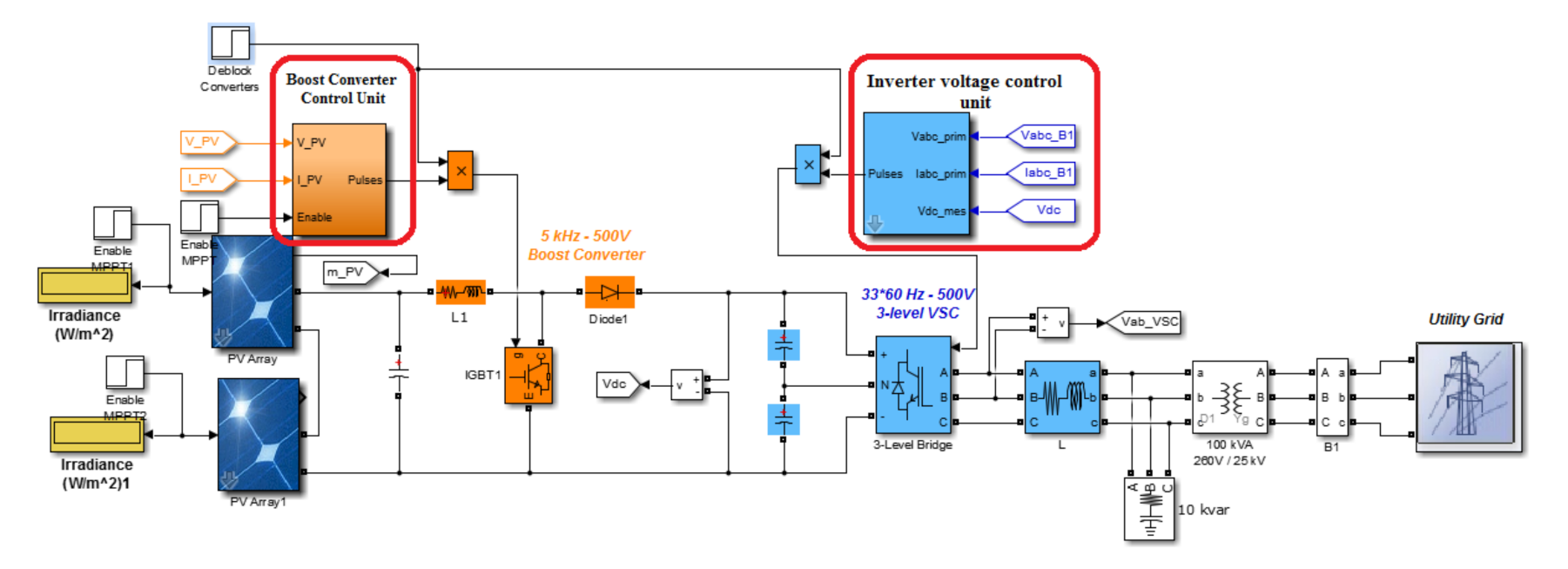
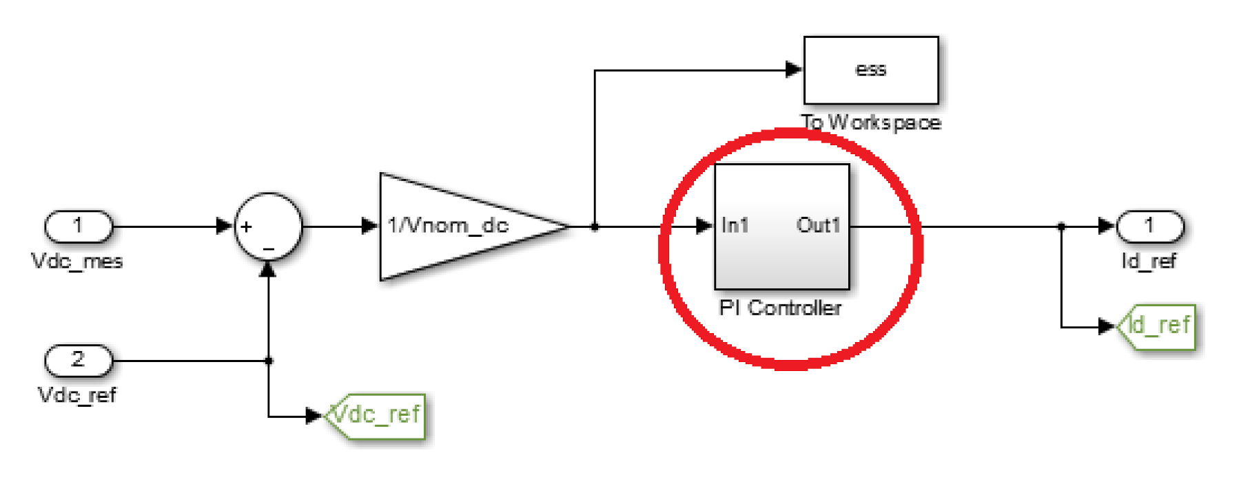
The PV system undergoing PS is modeled using MATLAB/SIMULINK. This model is represented in Figure 3 and it consists mainly of two PV arrays. Each is built up of 3 series modules and 66 parallel-connected strings. The overall generation of both arrays is 120 KW. The PS is modeled by fixing the input irradiance of the first PV array at its maximum value (1000 W/m2), while the input irradiance of the second one is changing. A second order amplifier (SOA) is utilized to process the duty cycle estimated by the MPPT unit for the boost converter, as shown in Figure 4, to enhance the output power under PS condition and to reduce oscillations. Additionally, the inverter’s voltage control unit is based on a PI controller used to regulate the DC-link voltage as shown in Figure 5. The sampling time is 100 μs. The paper presents optimization techniques to tune the controller’s parameters encountered in red circles.

3. Objective Function and Optimization Algorithms

3.1. Objective Function

This study is defined to be multi-constrained and single objected. It aims to tune the initial settings of duty cycle of the boost converter, in addition to the gains of the second order amplifier (SOA) and the gains of the PI controller used for the DC-link voltage regulation. This tuning is performed to maximize the output power and energy of the lumped PV arrays under PS conditions. The formulation of the different parameters is described as follows:
According to [48], the initial duty cycle Dc is tuned under the constraints described in Equation (1), where SOA includes two gains to be optimized, named DD and MT, which are defined by the transfer function, T.F1, in Equation (2) [49]. The parameters of the SOA are defined in Equation (3) [50]. Moreover, the transfer function of the PI controller used for the DC-link voltage regulation, T.F2, is represented by Equation (4) [50,51]. The objective function Obj1 required to be maximized which is the sum of the per unit power and energy harvested from the PV arrays as given by Equation (5).
0.1 D c 0.9 ,
T . F 1 =   1 s 2 + DD . s + MT ,
DD =   1 C t ,   and   MT =   1 C t D t ,
T . F 2 = P + I s ,
Obj 1 =   1 max . energy × 0 t P tot   dt + P tot max . power ,
where
  • Dc—the initial setting of duty cycle of the DC booster.
  • Ct—the charging time of the amplifier (sec)
  • Dt—the discharging time of the amplifier (sec)
  • P—the proportional gain of the PI controller
  • I—the integral gain of the PI controller
  • Ptot—the total output power of the lumped arrays (W)
  • DD and MT—the gains used in SOA transfer function. They are the functions of the charging and discharging times of the SOA (sec-2).

3.2. The Proposed Optimization Algorithm (EPO)

Two optimization algorithms are proposed in this paper. The first is the cuttlefish algorithm (CFA), which is proved to be a very effective optimization algorithm [51,52]. The second proposed optimization algorithm used for solving the objective function of (5) is the emperor penguin optimizer (EPO). The EPO is a new meta-heuristic algorithm that was developed by Dhiman in 2018 [53]. The EPO algorithm was inspired by social huddling behavior of emperor penguins. The original environment of emperor penguins is the Antarctica continent and the temperature during winter may fall to a very low level, which would make it very hard for emperor penguins to survive. That’s why emperor penguins flock huddle in behavior that would help all individuals to keep their body temperature in a quite suitable range for survival. Huddling behavior is confined to emperor penguins only. It is dependable on many factors, such as temperature, distance, and effective movers throughout the huddle. The EPO algorithm is based on all these factors and more, where the temperature and the distance are emulated in the observer and update equations, respectively. The EPO algorithm is tested for several optimization problems and has proved its effectiveness. The main purpose of the emperor penguins huddling is to maximize the ambient temperature in the huddle and conserve energy. Therefore, the value of temperature T is dependent on the radius of the huddle polygon R as follows:
T =   0   ,   if   R > 1 1   ,   if   R < 1 ,
The temperature profile T0 is a factor that is responsible for exploration and the exploitation process. It is calculated as follows:
T 0 = T MI CI MI ,
where
  • T0—the temperature profile all around the huddle
  • MI—the maximum number of iterations
  • CI—the current iteration.
After generating the huddle boundary, the distance between the emperor penguin and the best obtained optimal solution D is computed as follows.
D = S A . P ep x C . P x ,
where
  • S(A)—the social forces of emperor penguins.
  • P (x)—the current position vector of the emperor penguin
  • A, C—anti-collision factors between neighbors
  • Pep(x)—the vector of the best optimal solutions found.
A and C are responsible for tuning the distance D, and they can be calculated from equations:
C = rand 1 ,
A = M × T 0 + P g ac × rand 2 T 0 ,
P g ac = P ep x P x ,
where
  • M—the movement parameter that maintains a gap between search agents for collision avoidance.
  • Pg (ac) defines the polygon grid accuracy by comparing the difference between emperor penguins.
Note that S(A) is responsible for moving towards the direction of best optimal search agent, and can be calculated from Equation (12), while the position is updated from Equation (13).
S A = f . e x / l e x 2 ,
P x + 1 = P ep x A × D ,
where
  • f & l—control parameters for better exploration and exploitation.
  • P(x+1) represents the next updated position of the emperor penguin.
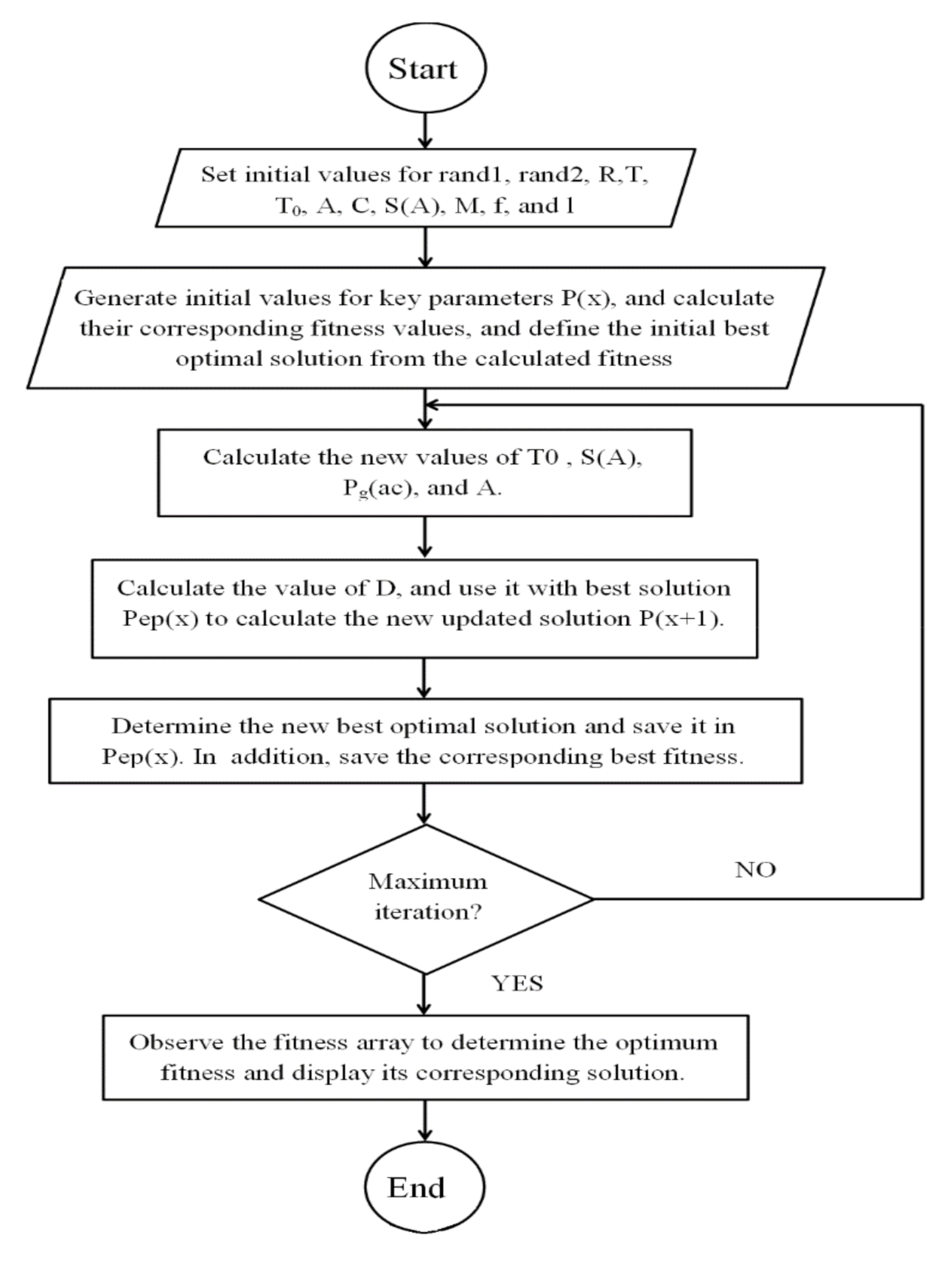
According to [53], the suggested values of the parameters used for the EPO algorithm are given in Table 1. Figure 6 shows the flow chart of EPO algorithm, while the main steps of performing EPO are as follows:
  • Step 1: set initial values for rand1, rand2, R, T, T0, A, C, S(A), M, f, and l.
  • Step 2: generate initial values for key parameters P(x), and calculate their corresponding fitness values (objective function).
  • Step 3: define the initial best optimal solution from the calculated fitness.
  • Step 4: start the first iteration by calculating the new values of T0, S(A), Pg(ac), and A.
  • Step 5: calculate the value of D, and use it with best solution Pep(x) to calculate the new updated solution P(x+1).
  • Step 6: determine the new best optimal solution and save it in Pep(x). Besides, save the corresponding best fitness.
  • Step 7: check if the iterations have ended, if not return to Step 4 and repeat until the maximum number of iterations is reached.
  • Step 8: observe the fitness array to determine the optimum fitness and display its corresponding solution.

4. Results and Comparison

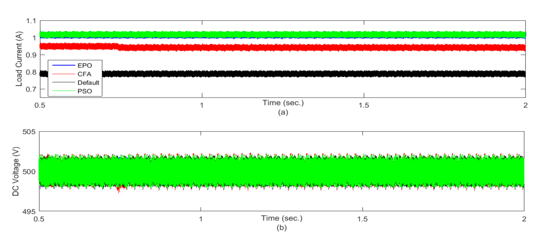
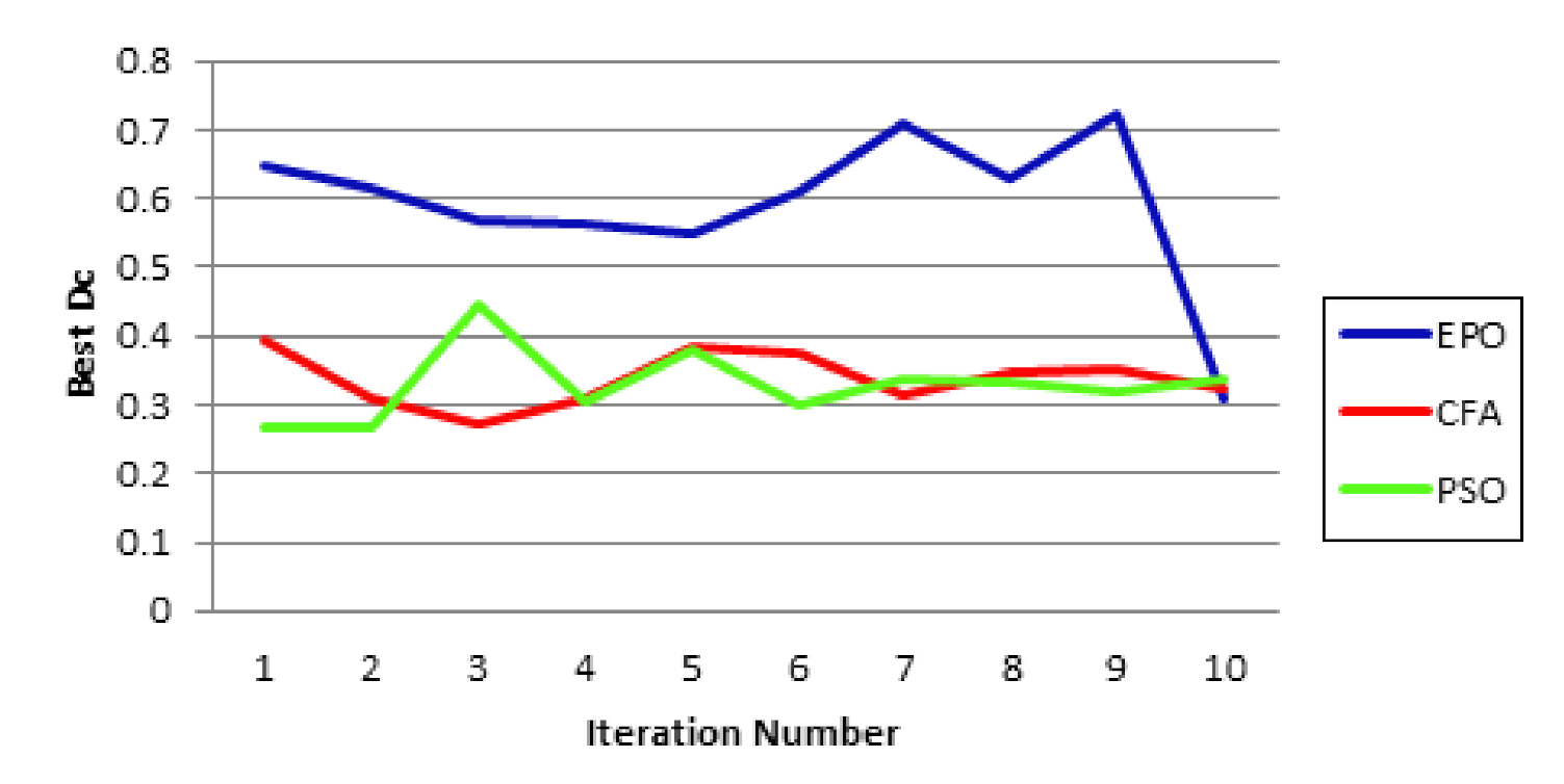
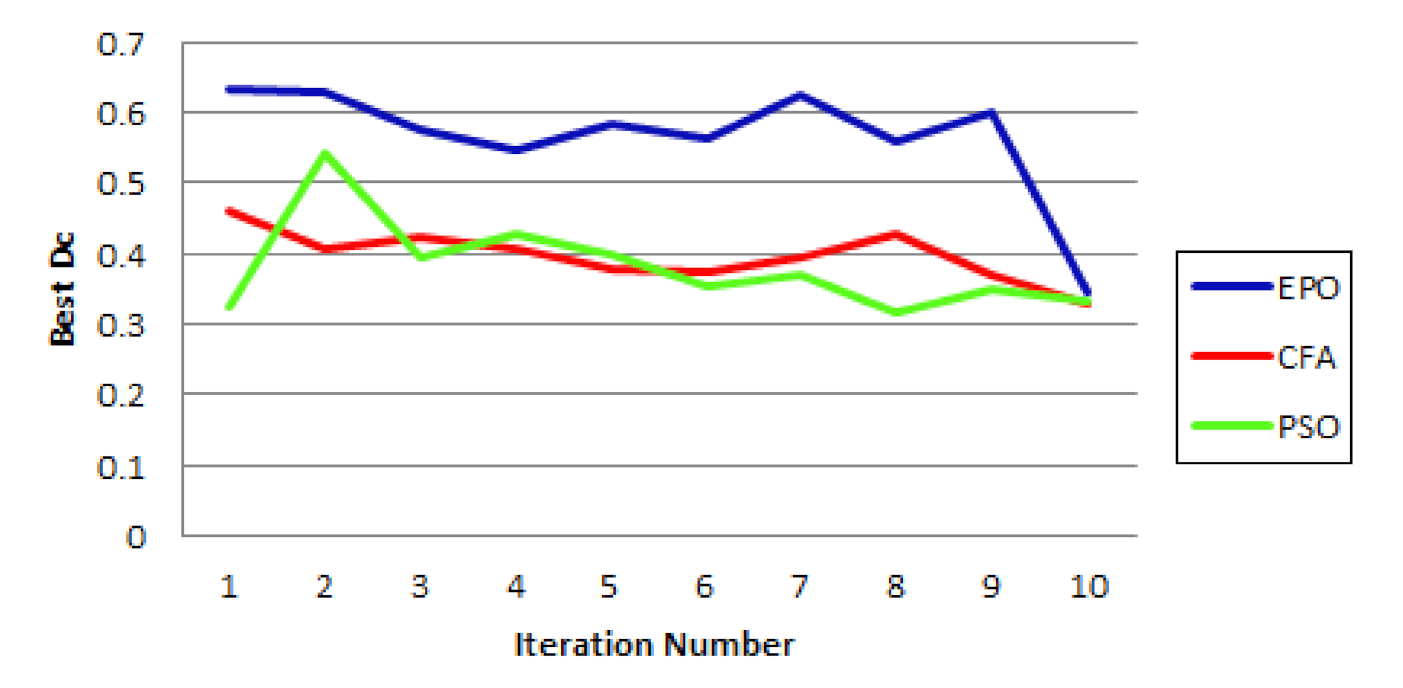
Three different PS patterns are considered. The irradiance of one PV array is set at the maximum value of 1000 W/m2, while the irradiance of the second PV array is set to a specific profile according to the case under study. The performance of the system is evaluated under each PS pattern when the parameters are optimized using either the PSO, the CFA or the proposed EPO algorithm. Five scenarios are presented. In the first and second scenarios, only the initial value of the duty cycle Dc is optimized. The third and fourth scenarios are dedicated to evaluate dynamic performance of the system under changing the PS pattern. In these cases, the system is fully optimized, where the gains of the PI controller and SOA are optimized in addition to the initial duty cycle. The last scenario is dedicated to check the dynamic performance of the system under different PS pattern than that used to obtain optimized parameters utilizing the proposed EPO algorithm. Table 2 and Table 3 show comparisons between the PSO, CFA, and EPO algorithms used for optimizing Dc for case 1 and case 2, respectively. The shaded PV array used for case 1 and case 2 is exposed to an irradiance of 800 W/m2 and 400 W/m2, respectively. For case 1, Figure 7a shows the duty cycle. Meanwhile, Figure 7b shows the extracted power from the PV system using the default initial Dc compared to that optimized by CFA and EPO algorithms. As should be expected, the duty cycle is inversely proportional to the PV power. Figure 8a,b illustrates the current fed to grid and the DC-link voltage. It is obvious from these results that using the optimized initial setting of the duty cycle obtained from the proposed EPO algorithm improves the harvested PV power and consequently the current fed to the grid. Additionally, the load current is increased with the decrease of duty cycle as the PV power is increased, while the DC voltage is tightly regulated at a specific level for all cases. Moreover, the tracking efficiency for the three algorithms is compared in Figure 9. By observing it, the three algorithms reach very close results at the end of the last iteration; despite the search region of each one which is detected randomly within fixed pre-specified ranges for all of them. Figure 10 and Figure 11 give comparisons of case study 2, where the irradiance levels of the PV arrays are set to 1000 W/m2 and 400 W/m2. It is clear from the results that the proposed EPO algorithm succeeds to set the initial setting of the duty cycle to harvest more power from the PV arrays than that obtained from using the CFA. It is worth mentioned that the DC-link voltage is tightly regulated regardless the setting of the initial duty cycle since the parameters of the PI based voltage regulator is kept constant during the tests. Figure 12 illustrates the tracking efficiency for case 2. It is obvious that all algorithms converge to close optimum solutions despite their different search region.
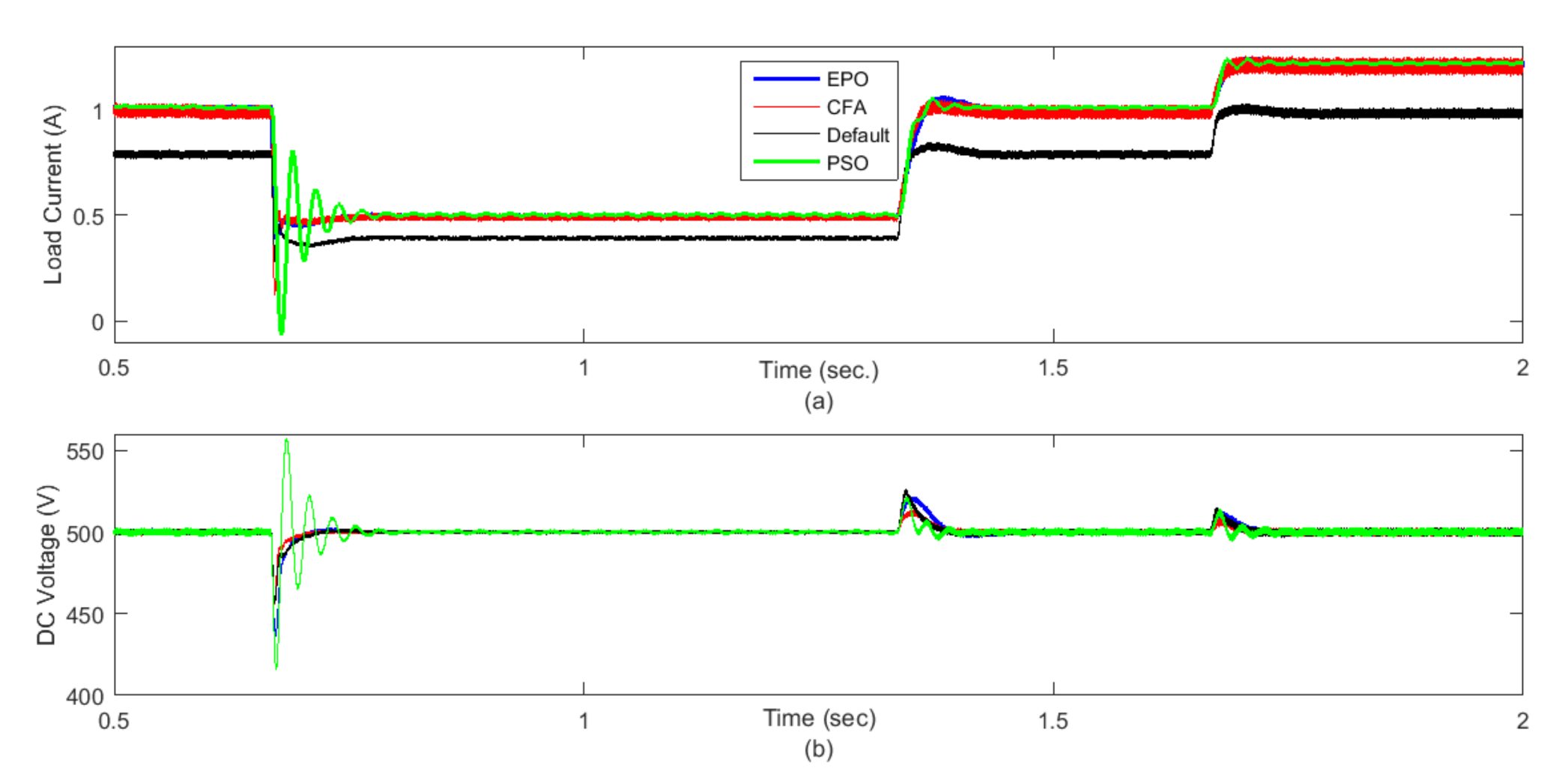
In the first two cases, static PS patterns are considered. Practically, this may occur if the PV array is installed near a fixed body, which may block the sunlight during certain period of the day. Despite it can rarely happen, these cases are considered to analyze the response of the system to the change in the initial setting of the duty cycle even in static mode. Case study 3 is dedicated to study the performance of the proposed PV system under dynamic PS pattern, shown in Figure 13a, where the irradiance of the shaded array is changed from 1000 W/m2 to 800 W/m2 to 400 W/m2 to 800 W/m2 to 1000 W/m2. These dynamic changes require that all the control parameters such as PI and SOA gains beside initial Dc value to be optimized. Results are recorded in Table 4 and optimized parameter values are given in Table 5. Moreover, the time needed for each algorithm—PSO, CFA, and EPO—to find the best solution is presented in Table 4. While the PSO takes the longest time to reach optimum setting, the EPO shows a little improvement compared to the CFA. Figure 13b shows the duty cycle, while Figure 13c illustrates the harvested PV power using the default Dc, PSO-optimized, CFA-optimized, and EPO-optimized parameters. This result reveals that using the optimized parameters of the proposed EPO algorithm results in more accurate operation of the MPPT compared to the CFA even under dynamic PS conditions. It is observed that PSO results are quite divergent to that of EPO. Figure 14a indicates that using the PSO algorithm results in severe oscillations in the grid current during transition from mode to another. Consequently, the DC link voltage may experience a severe overshoot as illustrated in Figure 14b. However, using the proposed EPO algorithm results in the best performance compared to the other techniques. Despite the PSO results in slightly higher power and energy harvesting than the EPO, its corresponding grid current and DC voltage are not acceptable. Figure 15 illustrates the tracking efficiency of case 3 and shows how close the solutions of EPO and PSO at the end of last iteration.
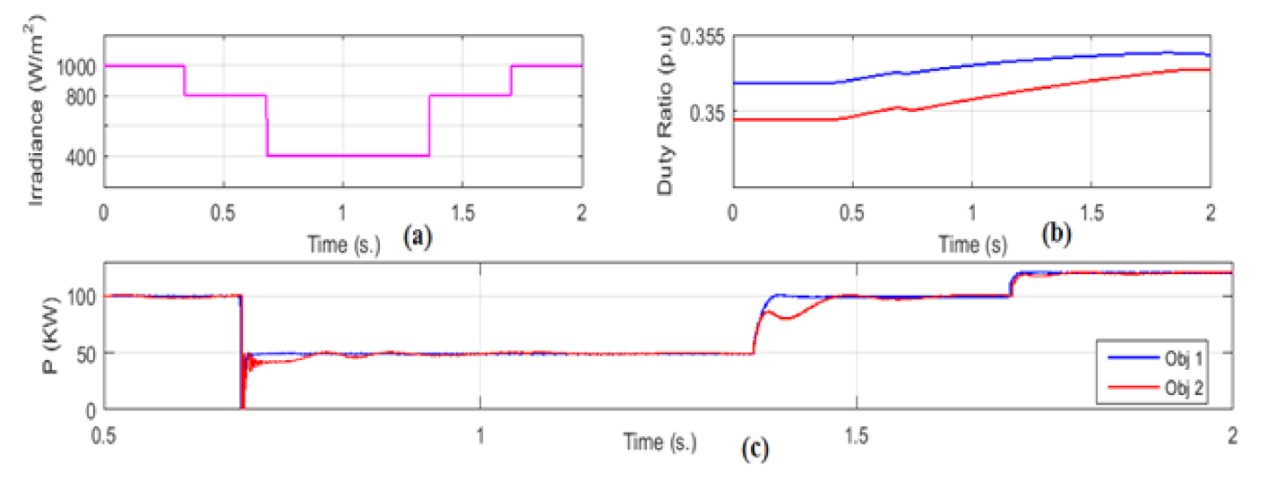
Case 4 is dedicated to evaluate the proposed objective function. The irradiance profile is the same as in case 3. However, a comparison is made between two objective functions given in Table 6. The first one obj1 is given in Equation (5). The second objective function Obj2 given in Equation (14), where the optimization process is focused only on maximizing power value, without taking into account the harvested energy. Figure 16 and Figure 17 present the results of this case. It is obvious that eliminating the energy term from the objective function deteriorate the dynamic system performance. Using the optimized parameters, when the energy term is considered in the objective function, results in fast dynamic response without oscillations.
Obj 2 = P tot max . power .
The last case is dedicated to check the robustness of using the optimized parameters using the proposed EPO algorithm under a PS profile different than used in the optimization process. The irradiance at the second PV array is set to a dynamic profile shown in Figure 18a, where it is set at 300 W/m2, then it is abruptly raised to 600 W/m2, then to 900 W/m2, and it falls again in reverse manner. Figure 18b illustrates the duty cycle. A comparison is made for the harvested power between the optimized initial duty cycle found by EPO and the default value in Figure 18c. Furthermore, the grid current and the DC-link voltage are shown in Figure 19a,b, respectively. It is obvious from these results that using the optimized parameters obtained from the proposed EPO algorithm improve the harvested PV power and consequently the current fed to the grid.

5. Conclusions

The paper shows that optimizing the initial setting of the duty cycle is quite an effective way of handling the drawbacks of partial shading on PV systems. However, under dynamic partial shading patterns, it is preferable to fully optimize the PV system by tuning the gains of the PI controller used for the DC-link voltage regulation in addition to the duty cycle and SOA gains used for the boost converter to guarantee accurate performance. The EPO algorithm proved its effectiveness as a new meta-heuristic technique used for optimizing the system parameters. The EPO algorithm is quite easy to implement and its mathematical burden is lower than that of the CFA. Moreover, the results show that considering the energy term in the objective function results in faster response time without oscillations compared to objective function based only on the harvested power. Furthermore, testing the system assured its robustness to different dynamic changes in irradiance.

Author Contributions

Formal analysis, M.A.S. and M.A.A.; methodology, M.A.S. and M.A.A.; supervision, M.I.M., M.A.B. and M.A.A. All authors have read and agreed to the published version of the manuscript.

Funding

This research was funded by Future University in Egypt (FUE).

Institutional Review Board Statement

Not applicable.

Informed Consent Statement

Not applicable.

Data Availability Statement

Not applicable.

Conflicts of Interest

The authors declare no conflict of interest.

References

  1. Iftikhar, R.; Ahmad, I.; Arsalan, M.; Naz, N.; Ali, N.; Armghan, H. MPPT for photovoltaic system using nonlinear controller. Hindawi Int. J. Photoenergy 2018, 2018, 11. [Google Scholar] [CrossRef] [Green Version]
  2. Priyadarshi, N.; Padmanaban, S.; Kiran Maroti, P.; Sharma, A. An extensive practical investigation of FPSO-based MPPT for grid integrated PV system under variable operating conditions with anti-islanding protection. IEEE Syst. J. 2019, 13, 1861–1871. [Google Scholar] [CrossRef] [Green Version]
  3. El-Helw, H.M.; Al-Hasheem, M.; Marei, M.I. Control strategies for the DAB based PV interface system. PLoS ONE 2016, 11, e0161856. [Google Scholar] [CrossRef] [PubMed]
  4. Priyadarshi, N.; Padmanaban, S.; Bhaskar, M.S.; Blaabjerg, F.; Holm-Nielsen, J.B.; Azam, F.; Sharma, A.K. A hybrid photovoltaic-fuel cell-based single-stage grid integration with lyapunov control scheme. IEEE Syst. J. 2020, 14, 3334–3342. [Google Scholar] [CrossRef]
  5. Gupta, M.; Saxena, R. Modeling and comparative analysis of PV module with improved perturbation and observation based MPPT technique for PV applications. Arch. Curr. Res. Int. 2018, 15, 1–12. [Google Scholar] [CrossRef]
  6. Premila, T.R.; Krishna Kumar, R. A comprehensive review on various optimization techniques assisted perturb and observe MPPT algorithm for a PV system. Int. J. Pure Appl. Math. 2018, 118, 51–63. [Google Scholar]
  7. Bhaskar Ranjana, M.S.; Sanjeevikumar, P.; Blaabjerg, F.; Azam, F. New CUK–SEPIC converter based photovoltaic power system with hybrid GSA–PSO algorithm employing MPPT for water pumping applications. IET Power Electron. 2020, 13, 2824–2830. [Google Scholar]
  8. Priyadarshi, N.; Sanjeevikumar, P.; Holm-Nielsen, J.B.; Bhaskar Ranjana, M.S. Internet of things augmented a novel PSO-employed modified zeta converter-based photovoltaic maximum power tracking system: Hardware realization. IET Power Electron. 2020, 13, 2775–2781. [Google Scholar] [CrossRef]
  9. Yussif, N.; Sabry, O.H.; Abdel-Khalik, A.S.; Ahmed, S.; Mohamed, A.M. Enhanced quadratic V/f-based induction motor control of solar water pumping system. Energies 2021, 14, 104. [Google Scholar] [CrossRef]
  10. Padmanaban, S.; Priyadarshi, N.; Bhaskar, M.S.; Holm-Nielsen, J.B.; Hossain, E.; Azam, F. A hybrid photovoltaic-fuel cell for grid integration with Jaya-based maximum power point tracking: Experimental performance evaluation. IEEE Access 2019, 7, 82978–82990. [Google Scholar] [CrossRef]
  11. Sanjeevikumar, P.; Priyadarshi, N.; Holm-Nielsen, J.B.; Bhaskar, M.S.; Azam, F.; Sharma, A.K.; Hossain, E. A novel modified sine-cosine optimized MPPT algorithm for grid integrated PV System under real operating conditions. IEEE Access 2019, 7, 10467–10477. [Google Scholar] [CrossRef]
  12. Sanjeevikumar, P.; Priyadarshi, N.; Bhaskar, M.S.; Holm-Nielsen, J.B.; Ramachandaramurthy, V.K.; Hossain, E. A hybrid ANFIS-ABC based MPPT controller for PV system with anti-islanding grid protection: Experimental realization. IEEE Access 2019, 7, 103377–103389. [Google Scholar]
  13. Priyadarshi, N.; Padmanaban, S.; Mihet-Popa, L.; Blaabjerg, F.; Azam, F. Maximum power point tracking for brushless DC motor-driven photovoltaic pumping systems using a hybrid ANFIS-FLOWER pollination optimization algorithm. Energies 2018, 11, 1067. [Google Scholar] [CrossRef] [Green Version]
  14. Priyadarshi, N.; Sharma, A.K.; Azam, F. A hybrid firefly-asymmetrical fuzzy logic controller based MPPT for PV-wind-fuel grid integration. Int. J. Renew. Energy Res. 2017, 7, 1546–1560. [Google Scholar]
  15. Mazaheri Salehi, P.; Solyali, D. A review on maximum power point tracking methods and their application. J. Solar Energy Res. 2018, 3, 123–133. [Google Scholar]
  16. Ram, J.P.; Rajasekar, N.; Miyatake, M. Design and overview of maximum power point tracking techniques in the wind and solar photovoltaic systems: A review. Renew. Sustain. Energy Rev. 2017, 73, 1138–1159. [Google Scholar] [CrossRef]
  17. Huang, Y.; Chen, X.; Ye, C. A hybrid maximum power point tracking approach for photovoltaic systems under partial shading conditions using a modified genetic algorithm and the firefly algorithm. Hindawi Int. J. Photoenergy 2017, 2018, 13. [Google Scholar] [CrossRef] [Green Version]
  18. Kumar, J.; Bahrani, P. Comprehensive review on maximum power point tracking methods for SPV system. Int. Res. J. Eng. Technol. 2017, 4. [Google Scholar]
  19. Erdem, Z. A review of MPPT algorithms for partial shading conditions. Acta Phys. Pol. Ser. 2017, 132, 1128–1133. [Google Scholar] [CrossRef]
  20. Ishaque, K.; Salam, Z. A deterministic particle swarm optimization maximum power point tracker for photovoltaic system under partial shading condition. IEEE Trans. Ind. Electron. 2013, 60, 3195–3206. [Google Scholar] [CrossRef]
  21. Lyden, S.; Haque, M.E. A simulated annealing global maximum power point tracking approach for PV modules under partial shading conditions. IEEE Trans. Power Electron. 2016, 31, 4171–4181. [Google Scholar] [CrossRef]
  22. Mohanty, S.; Subudhi, B.; Ray, P.K. New MPPT design using grey wolf optimization technique for photovoltaic system under partial shading conditions. IEEE Trans. Sustain. Energy 2016, 7, 181–188. [Google Scholar] [CrossRef]
  23. Seyedmahmoudian, M.; Rahmani, R.; Mekhilef, S.; Oo, A.M.T.; Stojcevski, A.; Soon, T.K.; Ghandhari, A.S. Simulation and hardware implementation of new maximum power point tracking technique for partially shaded PV system using hybrid DEPSO method. IEEE Trans. Sustain. Energy 2015, 6, 850–862. [Google Scholar] [CrossRef]
  24. Sundareswaran, K.; Peddapati, S.; Palani, S. MPPT of PV systems under partial shaded conditions through a colony of flashing fireflies. IEEE Trans. Energy Convers. 2014, 29, 463–472. [Google Scholar]
  25. Sundareswaran, K.; Sankar, P.; Nayak, P.S.R.; Simon, S.P.; Palani, S. Enhanced energy output from a PV system under partial shaded conditions through artificial bee colony. IEEE Trans. Sustain. Energy 2015, 6, 198–209. [Google Scholar] [CrossRef]
  26. Alajmi, B.N.; Ahmed, K.H.; Finney, S.J.; Williams, B.W. A maximum power point tracking technique for partially shaded photovoltaic systems in microgrids. IEEE Trans. Ind. Electron. 2013, 60, 1596–1606. [Google Scholar] [CrossRef]
  27. AL-Emam, M.; Marei, M.I.; El-khattam, W. A maximum power point tracking technique for PV under partial shading condition. In Proceedings of the IEEE India International Conference on Power Electronics (IICPE), Jaipur, India, 13–15 December 2018. [Google Scholar]
  28. Boztepe, M.; Guinjoan, F.; Quesada, G.V.; Silvestre, S.; Chouder, A.; Karatepe, E. Global MPPT scheme for photovoltaic string inverters based on restricted voltage window search algorithm. IEEE Trans. Ind. Electron. 2014, 61, 3302–3312. [Google Scholar] [CrossRef]
  29. Batzelis, E.I.; Kampitsis, G.E.; Papathanassiou, S.A.; Manias, S.N. Direct MPP calculation in terms of the single-diode PV model parameters. IEEE Trans. Energy Convers. 2015, 30, 226–236. [Google Scholar] [CrossRef]
  30. Kang, B.K.; Kim, S.T.; Bae, S.H.; Park, J.W. Diagnosis of output power lowering in a PV array by using the Kalman-filter algorithm. IEEE Trans. Energy Convers. 2012, 27, 885–894. [Google Scholar] [CrossRef]
  31. Seyedmahmoudian, M.; Mekhilef, S.; Rahmani, R.; Yusof, R.; Renani, E.T. Analytical modeling of partially shaded photovoltaic systems. Energies 2013, 6, 128–144. [Google Scholar] [CrossRef] [Green Version]
  32. Manickam, C.; Raman, G.R.; Raman, G.P.; Ganesan, S.I.; Nagamani, C. A hybrid algorithm for tracking of GMPP based on P&O and PSO with reduced power oscillation in string inverters. IEEE Trans. Ind. Electron. 2016, 63, 6097–6106. [Google Scholar]
  33. Chen, K.; Tian, S.; Cheng, Y.; Bai, L. An improved MPPT controller for photovoltaic system under partial shading condition. IEEE Trans. Sustain. Energy 2014, 5, 978–985. [Google Scholar] [CrossRef]
  34. Tey, K.S.; Mekhilef, S. Modified incremental conductance algorithm for photovoltaic system under partial shading conditions and load variation. IEEE Trans. Ind. Electron. 2014, 61, 5384–5392. [Google Scholar]
  35. Alajmi, B.N.; Marei, M.I.; Abdelsalam, I. A multi-port DC/DC converter based on two- quadrant inverter topology for PV systems. IEEE Trans. Power Electron. 2021, 36, 522–532. [Google Scholar] [CrossRef]
  36. Elserougi, A.A.; Diab, M.S.; Massoud, A.M.; Abdel-Khalik, A.S.; Ahmed, S. A switched PV approach for extracted maximum power enhancement of PV arrays during partial shading. IEEE Trans. Sustain. Energy 2015, 6, 767–772. [Google Scholar] [CrossRef]
  37. Choi, U.; Blaabjerg, F.; Lee, K. Control strategy of two capacitor voltages for separate MPPTs in photovoltaic systems using neutral-point-clamped inverters. IEEE Trans. Ind. Appl. 2015, 51, 3295–3303. [Google Scholar] [CrossRef]
  38. Rani, B.I.; Ilango, G.S.; Nagamani, C. Enhanced power generation from PV array under partial shading conditions by shade dispersion using Su Do Ku configuration. IEEE Trans. Sustain. Energy 2013, 4, 594–660. [Google Scholar] [CrossRef]
  39. Marei, M.I.; Alajmi, B.; Abdelsalam, I.; Alhajri, M.F. A PV interface system based on high-gain high-frequency link converter. In Proceedings of the 2018 53rd International Universities Power Engineering Conference (UPEC), Glasgow, UK, 1–6 September 2018. [Google Scholar]
  40. Uno, M.; Kukita, A. Two-switch voltage equalizer using an LLC resonant inverter and voltage multiplier for partially shaded series-connected photovoltaic modules. IEEE Trans. Ind. Appl. 2015, 51, 1587–1601. [Google Scholar] [CrossRef]
  41. Ghasemi, M.A.; Foroushani, H.M.; Parniani, M. Partial shading detection and smooth maximum power point tracking of PV arrays under PSC. IEEE Trans. Power Electron. 2016, 31, 6281–6292. [Google Scholar] [CrossRef] [Green Version]
  42. Ji, Y.H.; Jung, D.Y.; Kim, J.G.; Kim, J.H.; Lee, T.W.; Won, C.Y. A real maximum power point tracking method for mismatching compensation in PV array under partially shaded conditions. IEEE Trans. Power Electron. 2011, 26, 1001–1009. [Google Scholar] [CrossRef]
  43. Ramson, S.J.; Raju, K.L.; Vishnu, S.; Anagnostopoulos, T. Nature inspired optimization techniques for image processing—A short review. In Nature Inspired Optimization Techniques for Image Processing Applications; Springer: Cham, Switzerland, 2019. [Google Scholar]
  44. Mekontso, C.; Abubakar, A.; Madugu, S.; Ibrahim, O.; Adediran, Y.A. Review of optimization techniques for sizing renewable energy systems. Comput. Eng. Appl. 2019, 8, 13–30. [Google Scholar] [CrossRef]
  45. Logeswarana, T.; Senthil Kumarb, A. A review of maximum power point tracking algorithms for photovoltaic systems under uniform and non-uniform irradiances. Energy Procedia 2014, 54, 228–235. [Google Scholar] [CrossRef] [Green Version]
  46. Kolluru, V.R.; Patjoshi, R.K.; Panigrahi, R. A comprehensive review on maximum power tracking of a photovoltaic system under partial shading conditions. Int. J. Renew. Energy Res. 2019, 9, 12. [Google Scholar]
  47. Alshareef, M.; Lin, Z.; Ma, M.; Cao, W. Accelerated particle swarm optimization for photovoltaic maximum power point tracking under partial shading conditions. Energies 2019, 12, 18. [Google Scholar] [CrossRef] [Green Version]
  48. Hussaian Basha, C.H.; Rani, C. Evolutionary and metaphor-metaheuristic MPPT techniques for enhancing the operation of solar PV under partial shading condition. Int. J. Innov. Technol. Explor. Eng. 2019, 8, 2206–2216. [Google Scholar]
  49. Omar, O.A.; Badra, N.M.; Attia, M.A. Enhancement of on-grid PV system under irradiance and temperature variations using new optimized adaptive controller. Int. J. Electr. Comput. Eng. 2018, 8, 2650–2660. [Google Scholar] [CrossRef]
  50. Sameh, M.A.; Badr, M.A.; Mare, M.I.; Attia, M.A. Enhancing the performance of photovoltaic systems under partial shading conditions using cuttlefish algorithm. In Proceedings of the 2019 8th International Conference on Renewable Energy Research and Applications (ICRERA), Brasov, Romania, 3–6 November 2019. [Google Scholar]
  51. Sameh, M.A.; Badr, M.A.; Badr MA, L.; Marei, M.I.; Attia, M.A. Optimized PIA controller for photovoltaic system using hybrid particle swarm optimization and cuttlefish algorithms. In Proceedings of the 2018 7th International Conference on Renewable Energy Research and Applications (ICRERA), Paris, France, 14–17 October 2018. [Google Scholar]
  52. Eesa, A.S.; Brifcani AM, A.; Orman, Z. A new tool for global optimization problems-cuttlefish algorithm. Int. J. Math. Comput. Phys. Electr. Comput. Eng. 2014, 8, 1235–1239. [Google Scholar]
  53. Dhiman, G.; Kumar, V. Emperor penguin optimizer: A bio-inspired algorithm for engineering problems. Knowl. Based Syst. 2018, 159, 20–50. [Google Scholar] [CrossRef]
Figure 1. Multiple peaked power–voltage (P–V) characteristics under the partial shading (PS) condition.
Energies 14 00751 g001
Figure 2. Flow cycle of evolutionary optimization methods.
Energies 14 00751 g002
Figure 3. PV system under study with circled blocks under study.
Energies 14 00751 g003
Figure 4. Controlled initial duty cycle included in the maximum power point tracking (MPPT) unit with the second order amplifier (SOA) connected.
Energies 14 00751 g004
Figure 5. PI controller used in the voltage control unit.
Energies 14 00751 g005
Figure 6. Flow chart of EPO.
Energies 14 00751 g006
Figure 7. Case 1: (a) the duty cycle; (b) the harvested PV power using EPO, cuttlefish algorithm (CFA), particle swarm optimization (PSO), and default Dc.
Energies 14 00751 g007
Figure 8. Case 1: (a) the grid current; (b) the DC-link voltage.
Energies 14 00751 g008
Figure 9. Tracking efficiency of case 1.
Energies 14 00751 g009
Figure 10. Case 2: (a) the duty cycle; (b) the harvested PV power using EPO, CFA, and default Dc.
Energies 14 00751 g010
Figure 11. Case 2: (a) the grid current; (b) the DC-link voltage.
Energies 14 00751 g011
Figure 12. Tracking efficiency of case 2.
Energies 14 00751 g012
Figure 13. Case 3: (a) the irradiance profile; (b) the duty cycle; (c) the harvested PV power using EPO, CFA, PSO, and default parameters.
Energies 14 00751 g013
Figure 14. Case 3: (a) the grid current; (b) the DC-link voltage.
Energies 14 00751 g014
Figure 15. Tracking efficiency of case 3.
Energies 14 00751 g015
Figure 16. Case 4: (a) the irradiance profile; (b) the duty cycle; (c) the harvested PV power using Obj1 and Obj2 by EPO.
Energies 14 00751 g016
Figure 17. Case 4: (a) the grid current; (b) the DC-link voltage.
Energies 14 00751 g017
Figure 18. The robustness test applied to the system: (a) the irradiance profile; (b) the duty cycle; (c) the harvested PV power using EPO, and default Dc.
Energies 14 00751 g018
Figure 19. The robustness test applied to the system: (a) the grid current; (b) the DC-link voltage.
Energies 14 00751 g019
Table 1. Settings of parameters used for the emperor penguin optimizer (EPO) algorithm [53].
ParameterMRand 1Rand 2fl
Minimum valueSet to 20021.5
Maximum value1132
Table 2. Case 1 of partial shading condition when the irradiance of the second PV array is 800 w/m2.
ParameterDefaultPSOCFAEPO
DC0.50.3386290.39740.3394
Energy (KW. sec)155.02196.978184.79197.843
Max power (KW)78.28299.8994.08100.7
Max Power (%)74.5595.1789.695.9
Table 3. Case 2 of partial shading condition when the irradiance of the second PV array is 400 w/m2.
ParameterDefaultPSOCFAEPO
DC0.50.32890.40520.3599
Energy (KW. sec)77.938100.3490.24598.488
Max power (KW)38.8450.1245.9349.05
Max power (%)76.1598.2790.0596.17
Table 4. Case 3 of dynamic PS pattern.
ParameterDefaultPSOCFAEPO
DC0.50.3330.36380.3537
Energy (KW. sec)139.86179.3173.07173.75
Max power (KW)97.75121.5119.91120.66
Max power (%)79.498.7897.4898.09
Consumed time (sec.)-60.4559.3158.98
Table 5. Optimized values of parameters.
ParameterPSOCFAEPO
Kp108.16243.408
Ki811.87721.3269433.7475
DD96.77112.9311149.1025
MT138.063184.1047211.7289
Table 6. Two objective cases.
ParameterObj1Obj2
DC0.35370.3489
Kp3.4080.3774
Ki433.747559.6189
DD149.1025142.7446
MT211.728975.5418
Publisher’s Note: MDPI stays neutral with regard to jurisdictional claims in published maps and institutional affiliations.