
Numerical and Experimental Study of Lightning Stroke to BIPV Modules


Abstract
:1. Introduction
2. Study of Lightning Attachment Characteristics to BIPV Modules
2.1. Numerical Simulation and Analysis
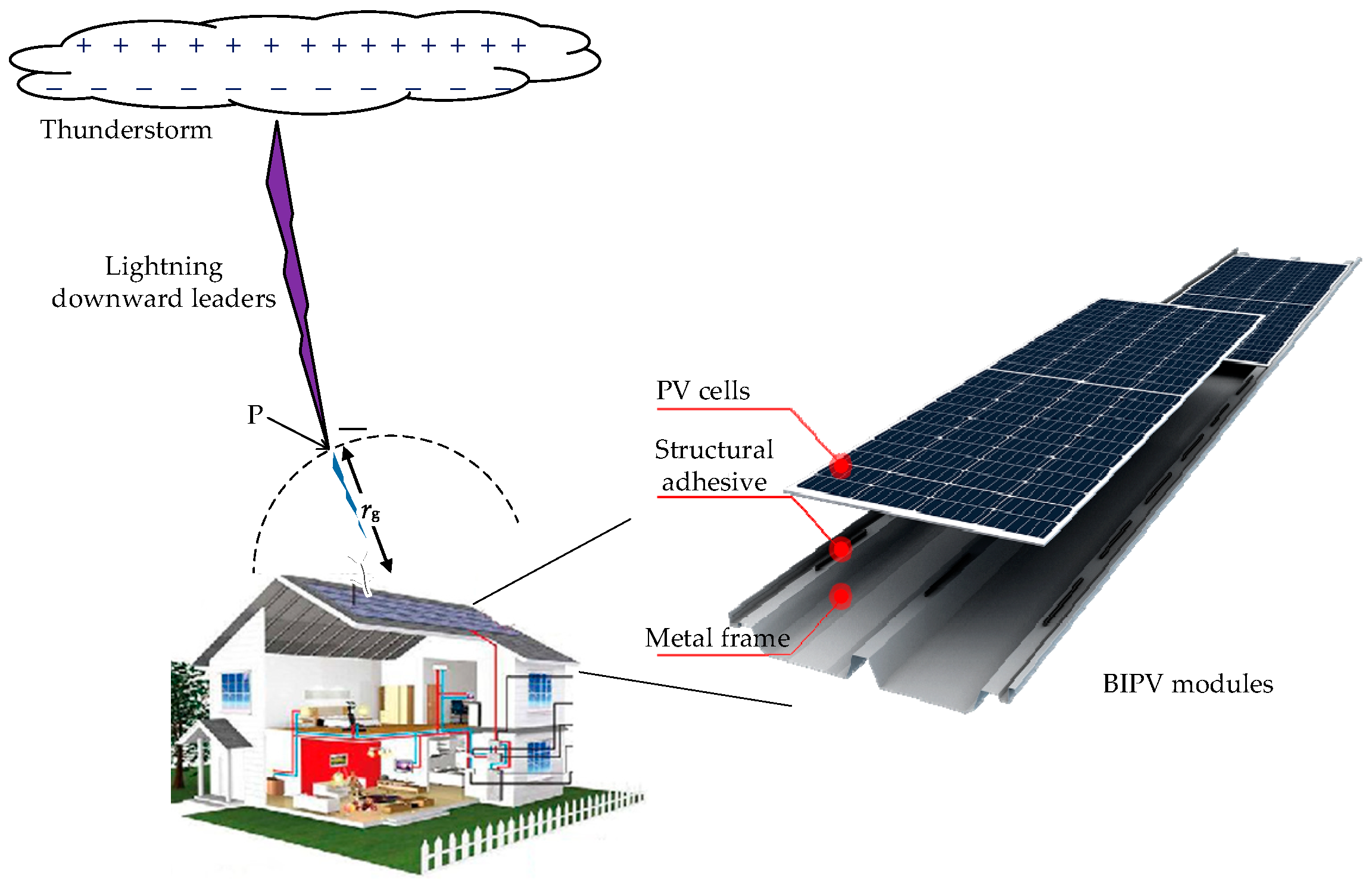
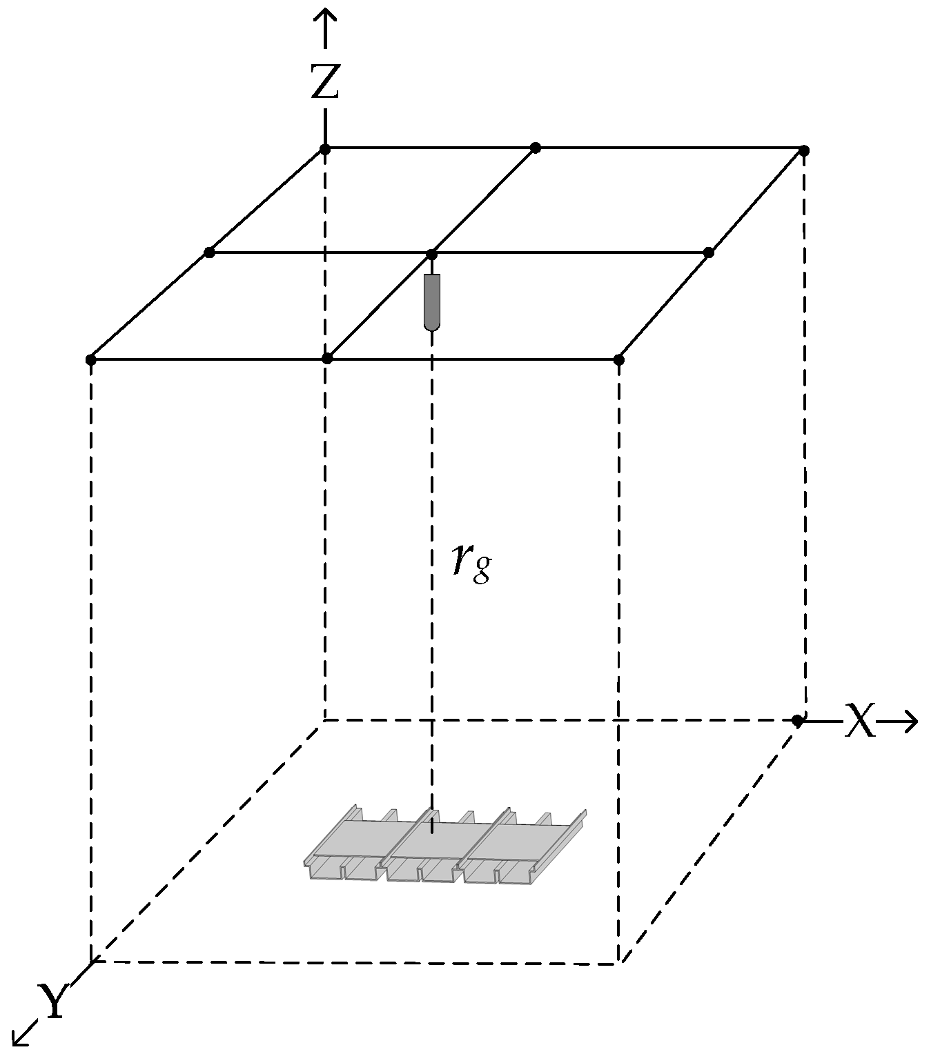
2.1.1. Modeling of Lightning Stroke to BIPV Modules
2.1.2. Electrostatic Field Theory
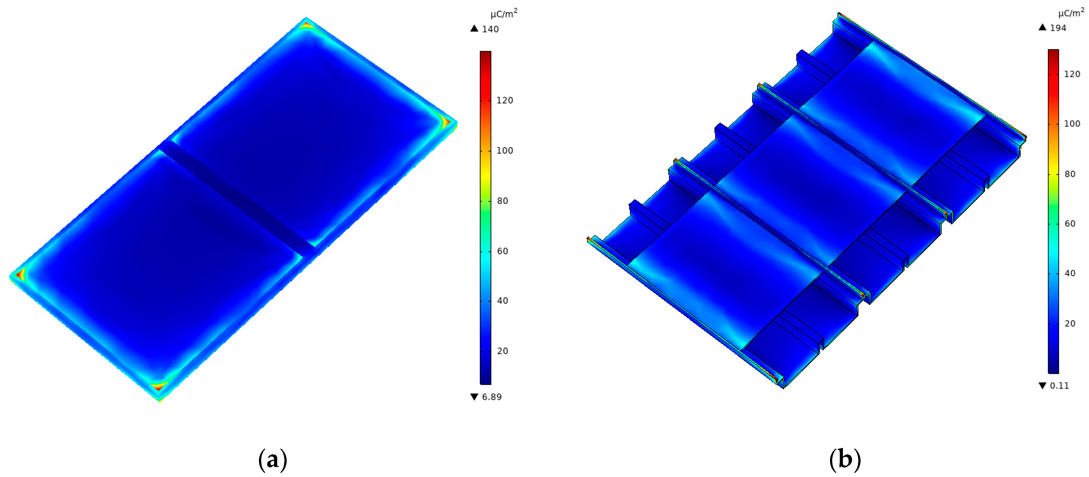
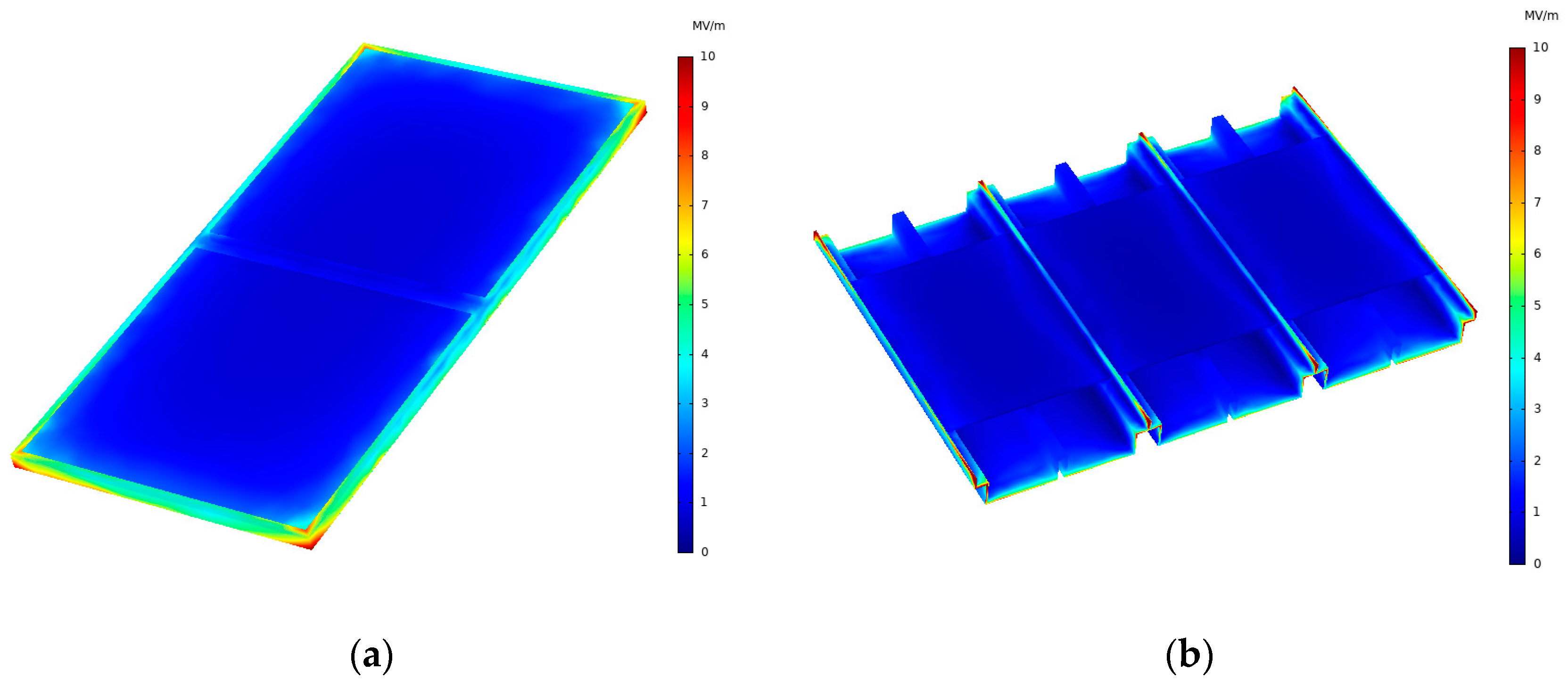
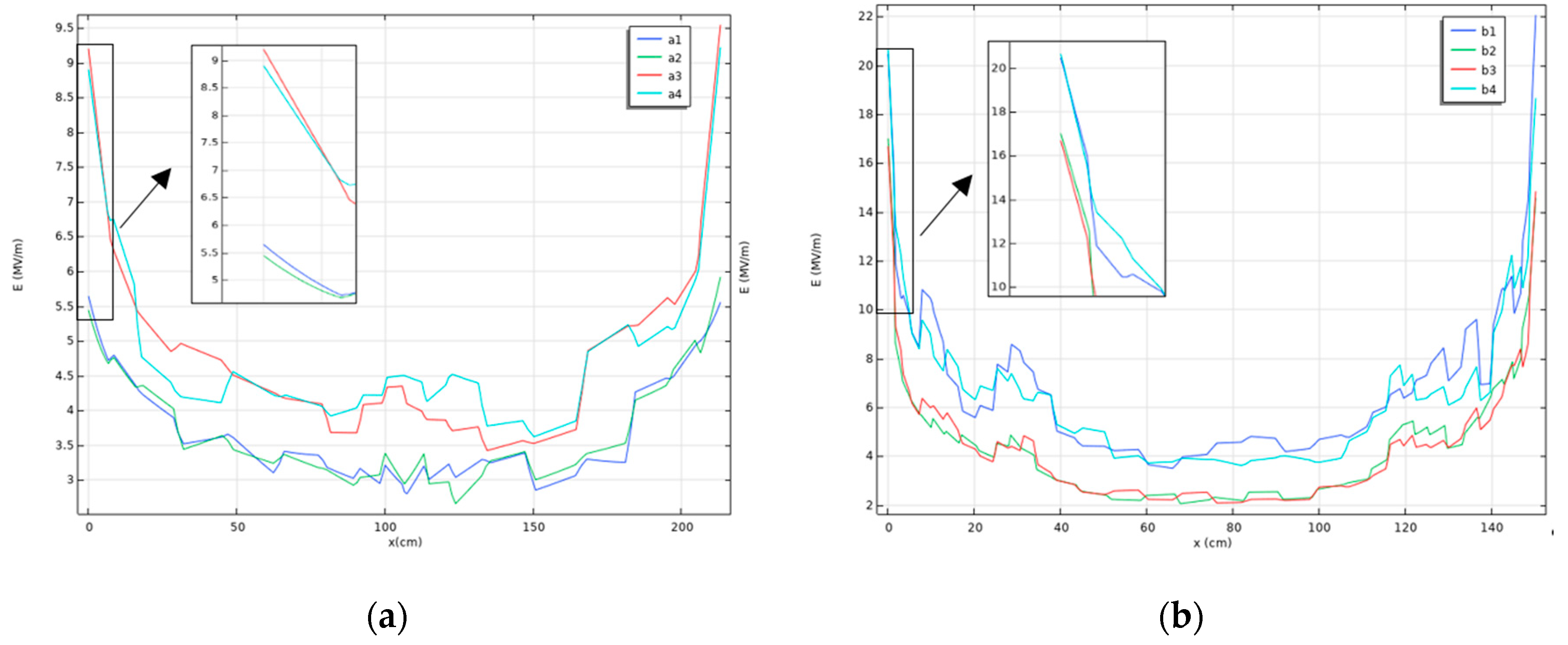
2.1.3. Simulation Results and Analysis
2.2. Experimental Study
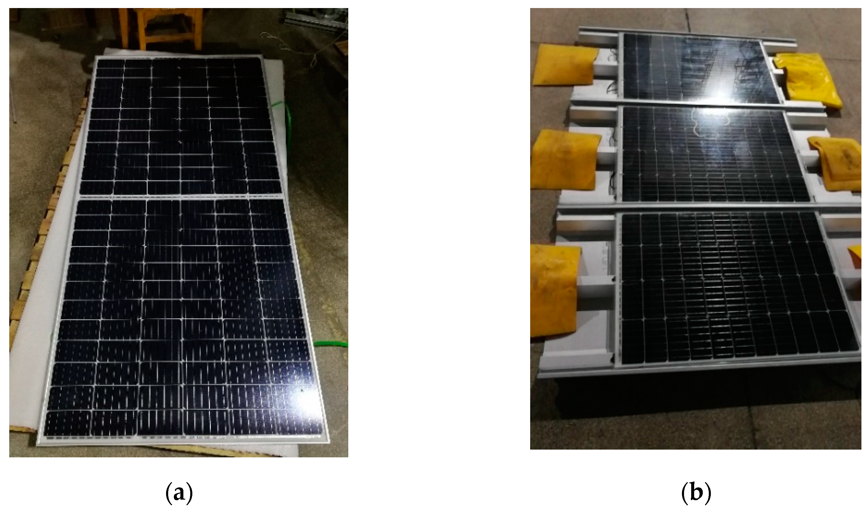
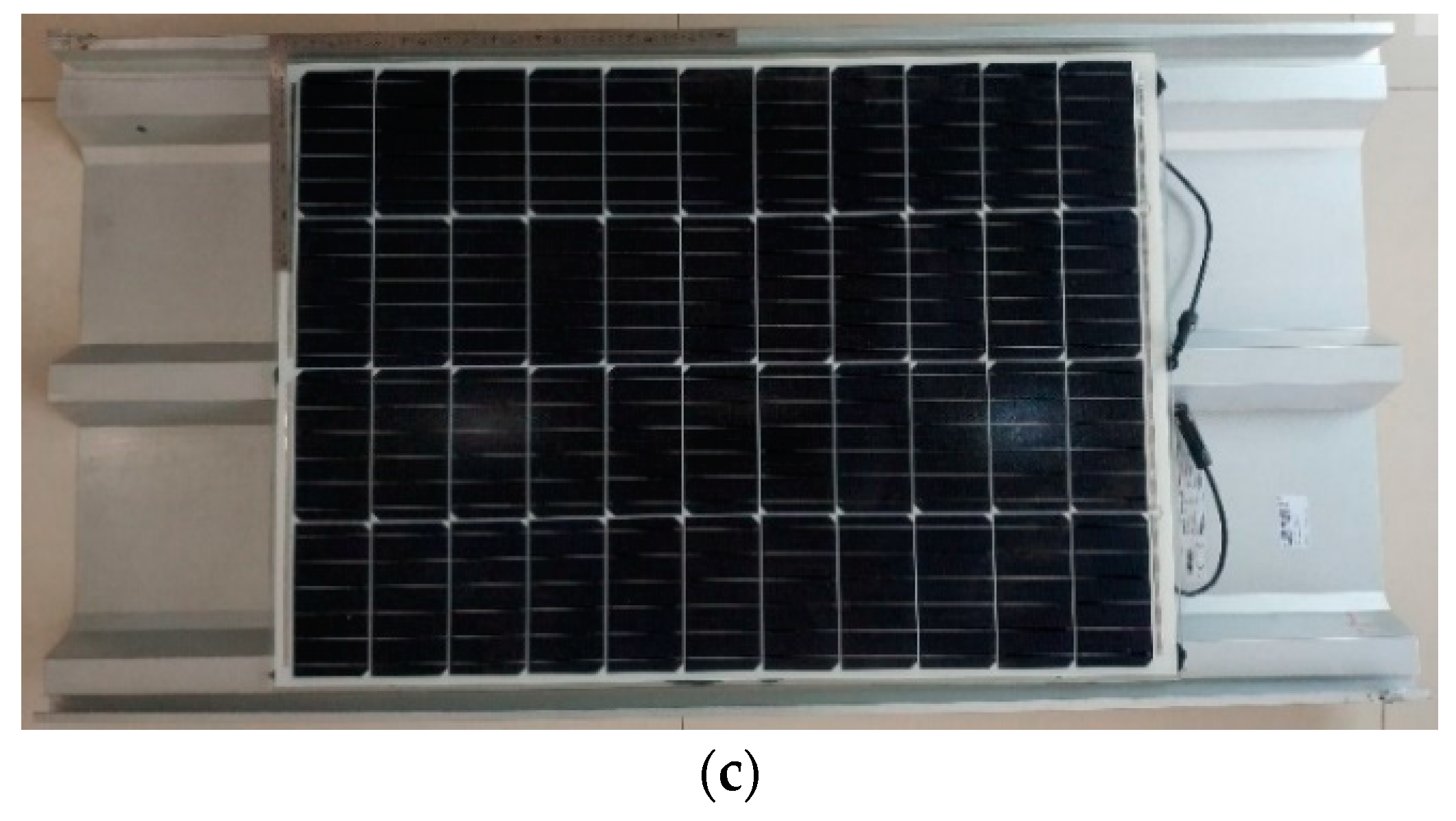
2.2.1. Sample Preparation
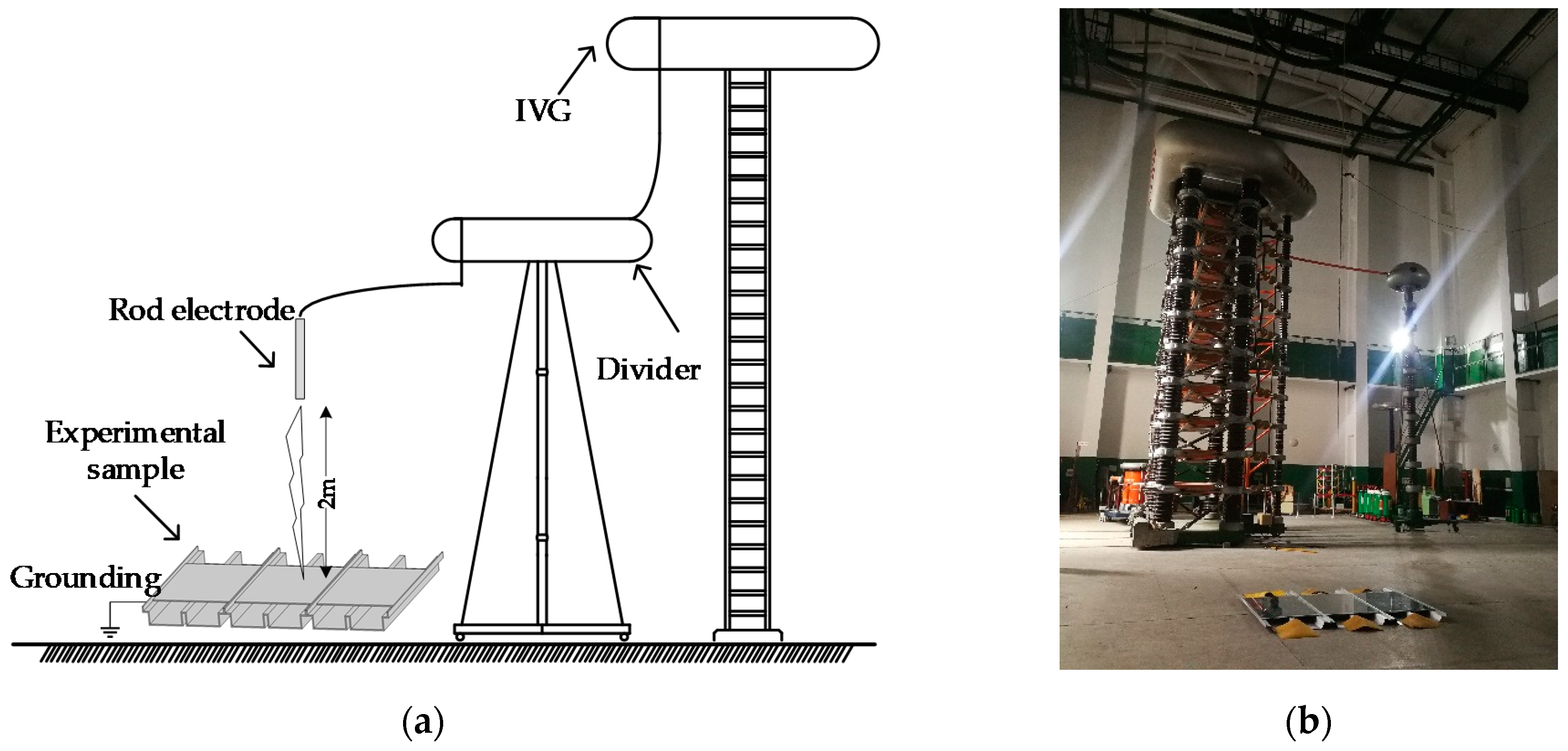
2.2.2. Experimental Method
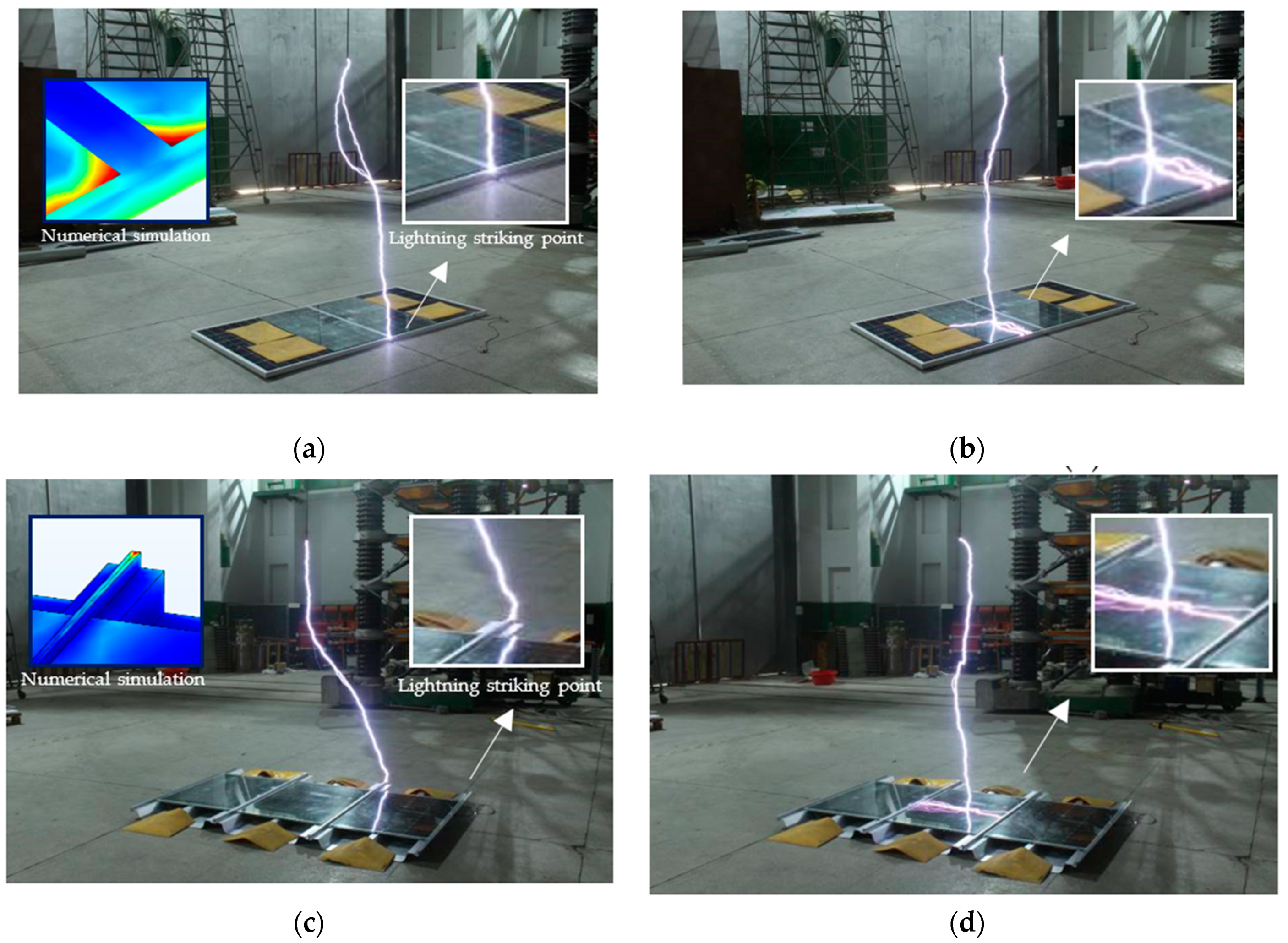
2.2.3. Experimental Results and Analysis
3. Study of Lightning Energy Withstand Capability to BIPV Modules
3.1. Numerical Simulation and Analysis
3.1.1. Thermoelectric Coupling Theory
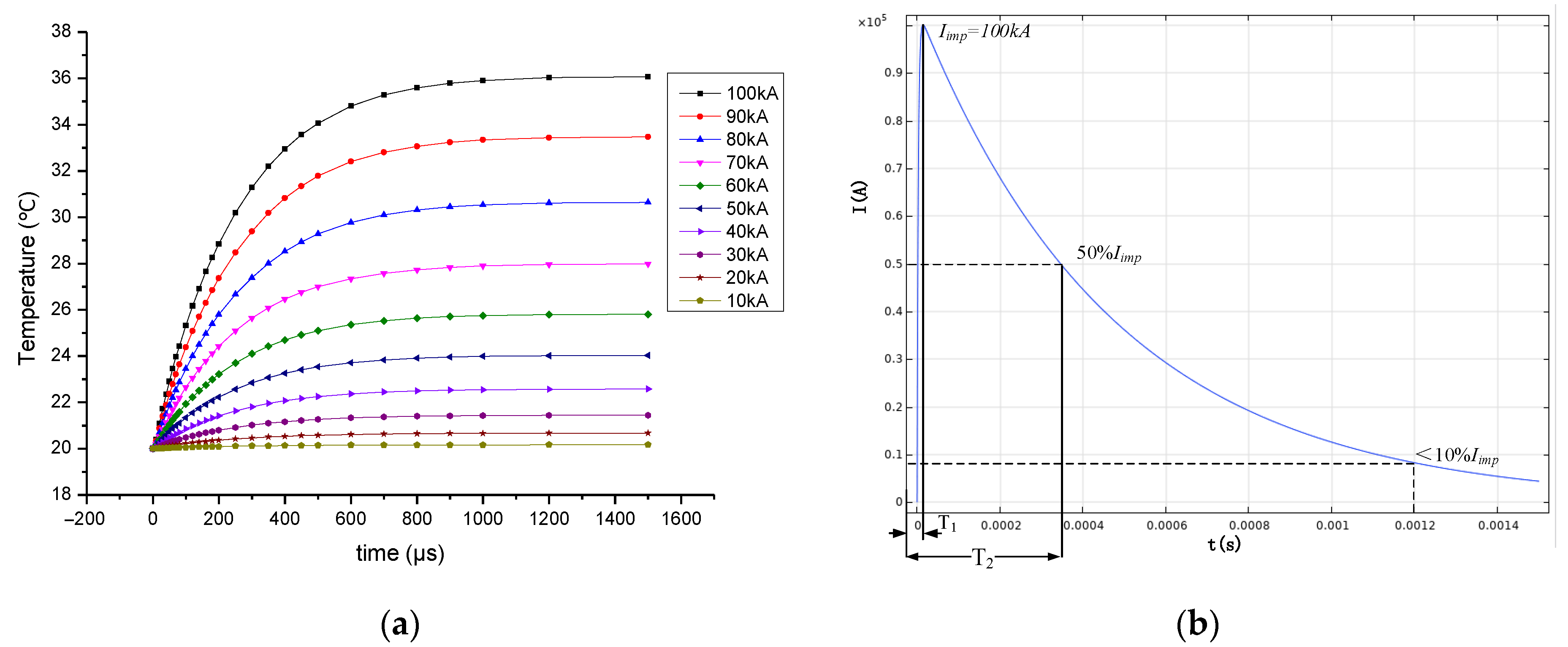
3.1.2. Modeling of Lightning Current
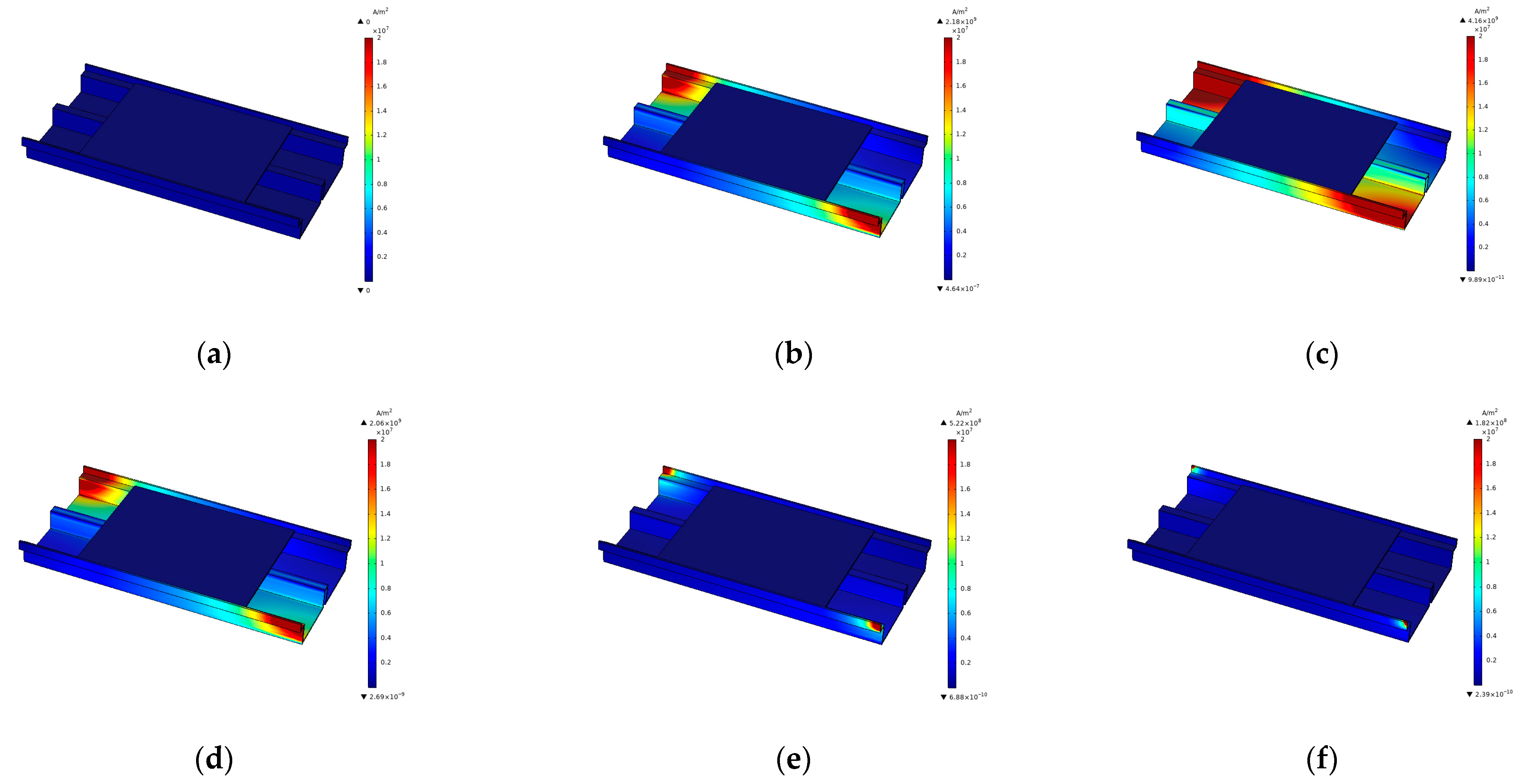
3.1.3. Simulation Result and Analysis
3.2. Experimental Study
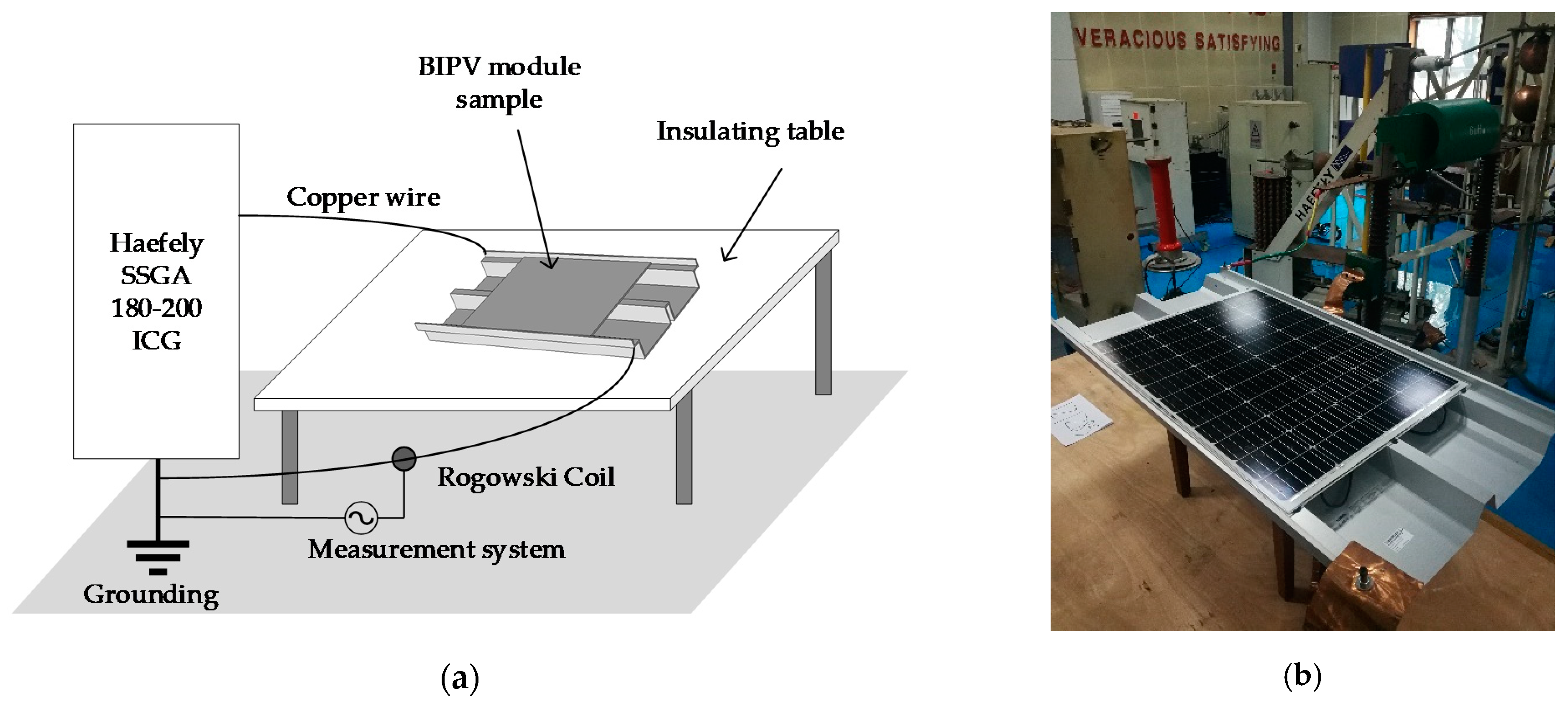
3.2.1. Experimental Method
3.2.2. Experimental Results and Analysis
4. Conclusions
- (a)
- The electrostatic field model when lightning downward leader above BIPV was built and analyzed with FEM software. An experiment was conducted to verify the numerical analysis. The numerical and experimental study of lightning attachment characteristics shows that the upper edge of the metal frame of BIPV modules is easier to gather charge which can enhance the electric field strength. The electric field strength on the surface of the BIPV module is 132% higher than that of framed double-glass PV module. Therefore, the BIPV module more easily intercepts lightning and the protection efficiency is improved by 114%.
- (b)
- The thermoelectric coupling analysis model is established to solve the potential, current and temperature of lightning BIPV modules during the process of lightning current flows through the metal frame of the BIPV module. The results show that the metal frame of the BIPV modules will not be damaged by the temperature rise of 16.07 °C. In the large impulse current experiment, the metal frame of the BIPV module meets the H-level (the highest level) requirements of the lightning conductor. The BIPV module is not damaged in the experiment which is consistent with the numerical simulation results.
Author Contributions
Funding
Institutional Review Board Statement
Informed Consent Statement
Data Availability Statement
Conflicts of Interest
References
- Ghosh, A. Potential of Building Integrated and Attached/Applied Photovoltaic (BIPV/BAPV) for Adaptive Less Energy-Hungry Building’s Skin: A Comprehensive Review. J. Clean. Prod. 2020, 276, 123343. [Google Scholar] [CrossRef]
- Chul-Sung, L.; Hyo-mun, L.; Min-joo, C.; Yoon, J. Performance Evaluation and Prediction of BIPV Systems under Partial Shading Conditions Using Normalized Efficiency. Energies 2019, 12, 273527. [Google Scholar]
- Barone, G.; Buonomano, A.; Cesare, F.; Forzano, C.; Giuzio, G.F.; Palombo, A. Passive and active performance assessment of building integrated hybrid solar photovoltaic/thermal collector prototypes: Energy, comfort, and economic analyses. Energy 2020, 209, 118435. [Google Scholar] [CrossRef]
- Escarre, J.; Li, H.-Y.; Sansonnens, L.; Galliano, F.; Cattaneo, G.; Heinstein, P.; Nicolay, S.; Bailat, J.; Eberhard, S.; Ballif, C.; et al. When PV modules are becoming real building elements: White solar module, a revolution for BIPV. In Proceedings of the 2015 IEEE 42nd Photovoltaic Specialist Conference (PVSC), New Orleans, LA, USA, 14–19 June 2015; pp. 1–2. [Google Scholar] [CrossRef]
- Lόpez, C.S.P.; Bonomo, P.; Frontini, F.; Medici, V.; Nespoli, L. Performance assessment of a BIPV Roofing Tile in outdoor testing. In Proceedings of the 2017 IEEE 44th Photovoltaic Specialist Conference (PVSC), Washington, DC, USA, 25–30 June 2017; pp. 2118–2123. [Google Scholar] [CrossRef]
- AlRashidi, H.; Issa, W.; Sellami, N.; Ghosh, A.; Mallick, T.K.; Sundaram, S. Performance Assessment of Cadmium Telluride-Based Semi-Transparent Glazing for Power Saving in Façade Buildings. Energy Build. 2020, 215, 109585. [Google Scholar] [CrossRef]
- Yu, S.; Xu, W.; Shi, Z. Study on Application of Random Bidirectional Discharge Model in Risk Assessment of Lightning Disaster at Airport. In Proceedings of the 2018 34th International Conference on Lightning Protection (ICLP), Rzeszow, Poland, 2–7 September 2018; pp. 1–4. [Google Scholar] [CrossRef]
- Jiang, T. Electrical Properties Degradation of Photovoltaic Modules Caused by Lightning Induced Voltage. Ph.D. Thesis, Mississippi State University, Starkville, MS, USA, May 2014. [Google Scholar]
- Guo, F.-Y.; Wang, Y.; Huang, M.-D. Design of Photovoltaic Building Lightning Protection Equipment Monitoring and Early Warning System. In Proceedings of the 26th Chinese Control and Decision Conference (2014 CCDC), Changsha, China, 31 May–2 June 2014; pp. 2902–2906. [Google Scholar]
- Fallah, N.; Gomes, C.; Ab Kadir, M.Z.A.; Nourirad, G.; Baojahmadi, M.; Ahmed, R.J. Lightning protection techniques for roof-top PV systems. In Proceedings of the 2013 IEEE 7th International Power Engineering and Optimization Conference (PEOCO), Langkawi, Malaysia, 3–4 June 2013; pp. 417–421. [Google Scholar] [CrossRef]
- Benesova, Z.; Haller, R.; Birkl, J.; Zahlmann, P. Overvoltages in photovoltaic systems induced by lightning strikes. In Proceedings of the 2012 International Conference on Lightning Protection (ICLP), Vienna, Austria, 2–7 September 2012; pp. 1–6. [Google Scholar] [CrossRef]
- Phanthuna, N.; Thongchompoo, N.; Plangklang, B.; Bhumkittipich, K. Model and experiment for study and analysis of Photovoltaic lightning effects. In Proceedings of the 2010 International Conference on Power System Technology, Hangzhou, China, 24–28 October 2010; pp. 1–5. [Google Scholar] [CrossRef]
- Karim, M.R.; Ahmed, M.R. Lightning Effect on a Large-Scale Solar Power Plant with Protection System. In Proceedings of the 2019 1st International Conference on Advances in Science, Engineering and Robotics Technology (ICASERT), Dhaka, Bangladesh, 3–5 May 2019; pp. 1–5. [Google Scholar] [CrossRef]
- Jia, Y.G.; Liu, H.Y.; Su, S.F.; Ding, S.L.; Han, Y.Q.; Liu, Y.; Zhang, X.S. Integrated Photovoltaic System Design and Key Points Analysis Based on Green Building. Appl. Mech. Mater. 2014, 641, 994–998. [Google Scholar] [CrossRef]
- Guo, F.Y.; Wang, Y.; Huang, M.D.; Yue, W. Fault Tree Establishment of Lightning Protection System Safety of Solar Photovoltaic Building. Adv. Mater. Res. 2013, 860, 210–213. [Google Scholar] [CrossRef]
- Zaini, N.H.; Ab-Kadir, M.Z.A.; Izadi, M.; Ahmad, N.I.; Radzi, M.A.M.; Azis, N.; Hasan, W.Z.W. On the effect of lightning on a solar photovoltaic system. In Proceedings of the 2016 33rd International Conference on Lightning Protection (ICLP), Estoril, Portugal, 25–30 September 2016; pp. 1–4. [Google Scholar] [CrossRef]
- Cho, J.; Kim, J.; Lee, T.-K.; Kim, K.-H.; Woo, J.-W. Analysis of Lightning Overvoltage According to Position of Lightning-Induced Voltage at the Solar Power Plant. In Proceedings of the 2019 11th Asia-Pacific International Conference on Lightning (APL), Hong Kong, 12–14 June 2019; pp. 1–4. [Google Scholar] [CrossRef]
- Dechthummarong, C.; Thepa, S.; Chenvidhya, D.; Jivacate, C.; Kirtikara, K.; Thongpron, J. Lightning impulse test of field-aged PV modules and simulation partial discharge within MATLAB. In Proceedings of the 2012 9th International Conference on Electrical Engineering/Electronics, Computer, Telecommunications and Information Technology, Phetchaburi, Thailand, 16–18 May 2012; pp. 1–4. [Google Scholar]
- Tamura, K.; Araki, K.; Kumagai, I.; Nagai, H. Lightning test for concentrator photovoltaic system. In Proceedings of the 2011 37th IEEE Photovoltaic Specialists Conference, Seattle, WA, USA, 10–15 June 2011; pp. 000996–000998. [Google Scholar] [CrossRef]
- Coetzer, K.M.; Wiid, P.G.; Rix, A.J. Investigating Lightning Induced Currents in Photovoltaic Modules. In Proceedings of the 2019 International Symposium on Electromagnetic Compatibility—EMC EUROPE, Barcelona, Spain, 2–6 September 2019; pp. 261–266. [Google Scholar] [CrossRef]
- IEC 62561-2:2018. Lightning Protection System Components (LPSC)—Part 2: Requirements for Conductors and Earth Electrodes. Available online: https://webstore.iec.ch/publication/29398 (accessed on 25 January 2018).
- Golde, R.H.; Perry, F.R. The frequency of occurrence and the distribution of lightning flashes to transmission lines. Trans. Am. Inst. Electr. Eng. 1945, 64, 902–910. [Google Scholar] [CrossRef]
- Young, F.S.; Clayton, J.M.; Hileman, A.R. Shielding of transmission lines. IEEE Trans. Power Appar. Syst. 1963, 82, 132–154. [Google Scholar]
- Love, E.R. Improvements in Lightning Stroke Modeling and Applications to Design of EHV and UHV Transmission Lines. Master’s Thesis, University of Colorado, Boulder, CO, USA, 1973. [Google Scholar]
- Whitehead, E.R. Cigre survey of the lightning performance of extra-high-voltage transmission lines. Electra 1974, 33, 63–89. [Google Scholar]
- Anderson, J.D. Transmission Line Reference Book-345 kV and above; Electric Power Research Institute: Palo Alto, CA, USA, 1982; pp. 142–144. [Google Scholar]
- IEEE Std 998-2012, IEEE Guide for Direct Lightning Stroke Shielding of Substations. Available online: https://ieeexplore.ieee.org/document/6656813 (accessed on 30 April 2013).
- Gamerota, W.R.; Elismé, J.O.; Uman, M.A.; Rakov, V.A. Current waveforms for lightning simulation. IEEE Trans. Electromagn. Compat. 2012, 54, 880–888. [Google Scholar] [CrossRef]
- Berger, K.; Anderson, R.B.; Kroninge, R.H. Parameters of Lighting Flashes. Electra 1975, 41, 23–37. [Google Scholar]
- Bruce, C.E.R.; Golde, R.H. The lightning discharge. Inst. Elect. Eng. 1941, 88, 487–505. [Google Scholar]

| Literature | K | b | Kg |
|---|---|---|---|
| Golde [22] | 3.30 | 0.78 | 1 |
| Young [23] | 27.00 | 0.32 | 1 (h < 18); 444/(462-h)(h > 18) |
| Love [24] | 10.00 | 0.65 | 1 |
| Whitehead [25] | 9.4 | 0.67 | 1 |
| Anderson [26] | 8.00 | 0.65 | 0.64 (EHV lines); 0.8 (UHV lines); 1 (other lines) |
| IEEE std 2012 [27] | 8 | 0.65 | 1 |
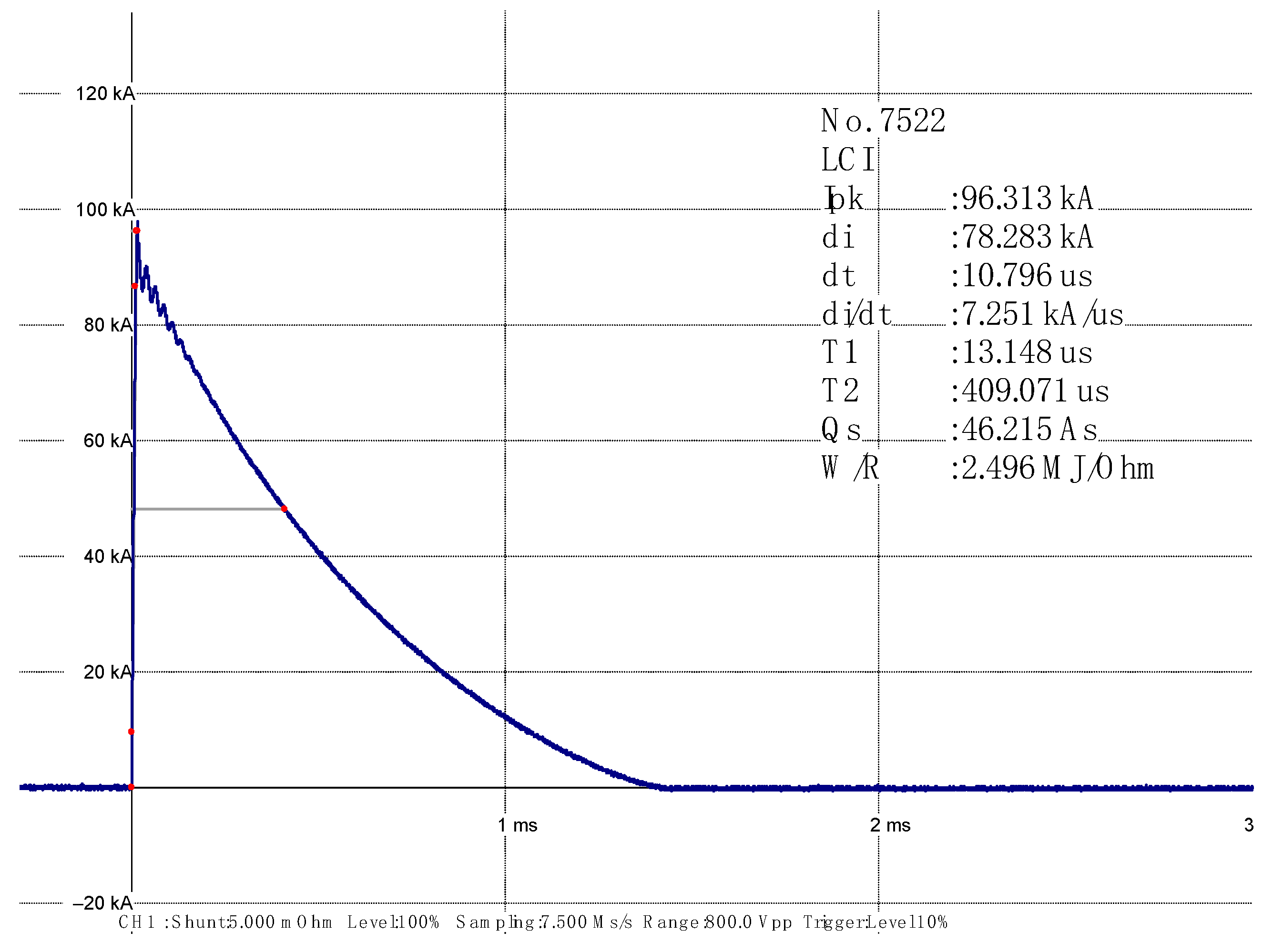
| No. | Peak Current/kA | T1/T2 (μs) | Transfer Charge/As | Specific Energy/(MJ * Ω−1) |
|---|---|---|---|---|
| 1 | 96.313 | 13.1/409.1 | 46.251 | 2496 |
| 2 | 96.508 | 12.9/397.1 | 44.674 | 2426 |
| 3 | 96.938 | 13.1/400.4 | 45.073 | 2451 |
Publisher’s Note: MDPI stays neutral with regard to jurisdictional claims in published maps and institutional affiliations. |
© 2021 by the authors. Licensee MDPI, Basel, Switzerland. This article is an open access article distributed under the terms and conditions of the Creative Commons Attribution (CC BY) license (http://creativecommons.org/licenses/by/4.0/).
Share and Cite
Bian, X.; Zhang, Y.; Zhou, Q.; Cao, T.; Wei, B. Numerical and Experimental Study of Lightning Stroke to BIPV Modules. Energies 2021, 14, 748. https://doi.org/10.3390/en14030748
Bian X, Zhang Y, Zhou Q, Cao T, Wei B. Numerical and Experimental Study of Lightning Stroke to BIPV Modules. Energies. 2021; 14(3):748. https://doi.org/10.3390/en14030748
Chicago/Turabian StyleBian, Xiaoyan, Yao Zhang, Qibin Zhou, Ting Cao, and Bengang Wei. 2021. "Numerical and Experimental Study of Lightning Stroke to BIPV Modules" Energies 14, no. 3: 748. https://doi.org/10.3390/en14030748
APA StyleBian, X., Zhang, Y., Zhou, Q., Cao, T., & Wei, B. (2021). Numerical and Experimental Study of Lightning Stroke to BIPV Modules. Energies, 14(3), 748. https://doi.org/10.3390/en14030748