Article

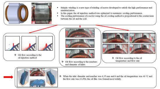
Study of Injection Method for Maximizing Oil-Cooling Performance of Electric Vehicle Motor with Hairpin Winding

1
School of Mechanical Engineering, Chung-Ang University, Seoul 06974, Korea
2
School of Computer Science and Engineering, Chung-Ang University, Seoul 06974, Korea
*
Author to whom correspondence should be addressed.
Energies 2021, 14(3), 747; https://doi.org/10.3390/en14030747
Submission received: 2 December 2020 / Revised: 25 January 2021 / Accepted: 26 January 2021 / Published: 1 February 2021

Abstract

:
The oil injection method was studied to maximize the cooling performance of an electric vehicle motor with a hairpin winding. The cooling performance of the motor using the oil cooling method is proportional to the contact area of the oil and the coil. A numerical analysis was conducted to examine the effect of the spray nozzle type on the oil flow. The dripping nozzle forms the thickest oil film on the coil, making it the most effective for cooling of hairpin-type motors. Subsequently, an experimental study was conducted to optimize the nozzle diameter and number of nozzles. When the inlet diameter and number was 6.35 mm and 6, the oil film formation rate was 53%, yielding the most uniform oil film. Next, an experiment was performed to investigate the effects of the oil temperature and flow rate on the oil flow. The oil film formation rate was the highest (83%) when the oil temperature was 40 °C and the flow rate was 6 LPM.

Graphical Abstract

1. Introduction

In recent years, interest in environmental issues has increased, accelerating the development of electric vehicles and increasing their demand. In contrast to conventional fuel vehicles, electric vehicles use only electricity and thus have no emissions [1]. The motor is the main power source of the electric vehicle and is the component that most significantly affects the performance and life of the vehicle. Electric vehicle motors must be high-power, and high efficiency for long and high-speed driving. In addition, because parts such as batteries and hydrogen tanks are located, they must be miniaturized. Thus, the heat-generation problem of motors is serious. The main heat losses of the motor are joule losses, iron losses, stray load loss, and mechanical losses [2,3,4]. The power density should be increased to improve the motor performance. However, this increases the loss of the motor and the amount of heat generated. In particular, the coil generates a large amount of heat owing to joule losses [5,6,7]. Therefore, effective cooling is important for high-performance motors. The magnet of the rotor is demagnetized at high temperatures. In other words, when the temperature of the motor rises, the magnet is demagnetized, and the drive stops and the performance decreases. Finally, the heat generated by the motor directly affects the performance and life of the electric vehicle.
There are several methods to cool the motor such as air cooling, water cooling, and oil cooling method [8,9]. Thus far, motors have mainly used air and water cooling. In air cooling, a fan is employed to inject air into the motor and cool it through forced convection [10]. Kim et al. [11] improved the cooling performance by optimizing the air-cooling method of a brushless DC motor. By optimizing the inlet position and inner length of the rotor, the performance was improved by 24.3% compared with a reference brushless DC motor. Kim et al. [12] analyzed the air-gap flow heating phenomena of a large-capacity induction motor using an air-cooling system. In the large-capacity motor, the temperature of the rotor was significantly higher than that of the stator. Hence, the air flowing between the rotor and the stator was heated by the rotor to a higher temperature than the stator. Thus, the stator was heated secondarily by air. The air gap of a motor exceeding 100 kW is in a superheating state; consequently, it is difficult to employ an air-cooling system. Electric vehicle motors that are at the same level as the performance of commonly used engine vehicles and capable of long-distance and high-speed driving use at least 100 kW of power [13], air cooling is not suitable.
In water cooling, a coolant flows along a flow path in the housing and cools the motor through conduction with the housing [14]. Pechánek et al. [15] compared two types of water-cooling electric motors: axial water flow and tangential water flow. The tangential water flow had a lower water velocity, corresponding to a smaller heat-transfer coefficient between the frame and the water (1018.7 W/m2K). The axial water flow had a higher water velocity and a larger heat-transfer coefficient (1886.4 W/m2K). The higher water velocity resulted in better cooling performance. Rehman et al. [16] compared various coolant jackets with different numbers of flow passes. Considering the pump performance, a cooling jacket with six passes at a flow rate of 10 LPM had the best cooling performance. The maximum temperature was approximately 100 °C. For an electric-vehicle motor, a large amount of heat is generated at the coil. The water-cooling method is not appropriate for removing heat from the coil. This method has a low heat-transfer rate in the radial direction, because the motor is cooled indirectly through the housing. Direct cooling is more effective for removing the heat inside the motor [17].
Oil cooling involves spraying oil directly on the coil, which is a heat source inside the motor. This method is suitable for cooling high-performance motors. However, research on oil cooling for motors is insufficient. Huang et al. [18] compared the indirect cooling method with the direct cooling method. In the indirect cooling method, a water jacket was used, similar to the case of water cooling. In the direct cooling method, a groove was formed between the stator and the housing to directly cool the stator with cooling oil. Under similar cooling conditions, the motor with a direct cooling channel reduced the average temperature on the stator by a factor of approximately two, improving the heat-transfer performance. However, because there was insulating paper between the stator and the coil, the heat transfer in the radial direction was insufficient. This method is not suitable for the removal of heat from the coil. Ponomarev et al. [19] cooled the motor through a method in which the inside of the electric motor was completely immersed in cooling oil. The rotor and stator were cooled via direct contact with the coolant. Thus, the cooling performance of the motor was improved, and the maximum temperature of the coil was 124 °C. However, the performance of the motor was degraded by the friction loss between the cooling oil and the rotor, making this motor unsuitable for electric vehicles. Davin et al. [20] cooled the motor by spraying oil directly onto a coil. Different types of injectors were compared, including the full cone nozzle, flat jet nozzle, dripping, and multi-jets. When a dripping injector was used, the average temperature of the end winding was approximately 109 °C, and the best cooling performance was achieved. Additionally, a higher flow rate corresponded to better cooling performance at the end winding. However, previous studies on the motor using the oil-cooling method focused on general windings such as toroidal winding and multi-strand winding. These motors have limitations in miniaturization and power improvement compared to hairpin type motors. The motor using a hairpin winding was recently developed, which can improve the power density by reducing the amount of unnecessary space between coils [13,21]. As a result, the size of the motor can be reduced, and performance can be improved. The hairpin winding is suitable for miniaturized high-performance motors; however, because of the considerable heat generation, a new cooling method is needed. However, research on the cooling of motors using hairpin windings is lacking.
In this study, the oil injection method was studied to maximize the cooling performance of an electric-vehicle motor with a hairpin winding. The Chevrolet Bolt EV motor, which uses the hairpin winding, was selected as the target motor. A parametric study is conducted to understand the injection conditions. It was selected as a variable of the factor that affects the behavior of oil, and the value of the variable to maximize the cooling effect was found. First, the effect of oil injection type on the oil film was compared through numerical analysis. The types of spray nozzles included a dripping nozzle and 45° and 60° full-cone nozzle. The effects of the nozzle diameter and the number of nozzles on the formation of the oil film were experimentally examined. Subsequently, the effects of the flow rate and temperature of the oil on the formation of the oil film were investigated. Finally, we proposed an optimal oil injection method for an oil-cooling motor using a hairpin winding. Using this method, a uniform oil film can be obtained on the coil. The results of this study provide important information regarding the flow characteristics and oil film formation of oil-cooling motors with hairpin windings. This provides important information for conducting relevant research, and they can contribute to the development of a high-performance motor for electric vehicles by providing an optimal injection method for improving the oil-cooling performance.

2. Materials and Methods

2.1. Motor Description

Figure 1 illustrates the stator and coil of the target motor. The Chevrolet Bolt EV motor from General Motors was selected as the target motor. Figure 1a shows the motor geometry used for the numerical analysis. The geometry of the motor was simplified to reduce the analysis time. The outer coil had a diagonal shape similar to that in the actual motor. The oil flow was affected by the coil shape. The inside of the coil was simplified as a cylinder that was blocked between the coils. Figure 1b shows the motor used in the experiment, which was a permanent-magnet synchronous motor with a hairpin winding. The motor had a peak torque of 360 Nm and a peak power of 150 kW. The stack length was 125 mm, and the outer diameter was 204 mm. The length of the stator used in the experiment was 180 mm. There were six coil conductors per slot of the stator. The end winding on the right side of the motor was called the crown part, and the end winding on the left side was called the welded part. There was white insulating paper between the protruding coils of the welded part, in contrast to the crown part.

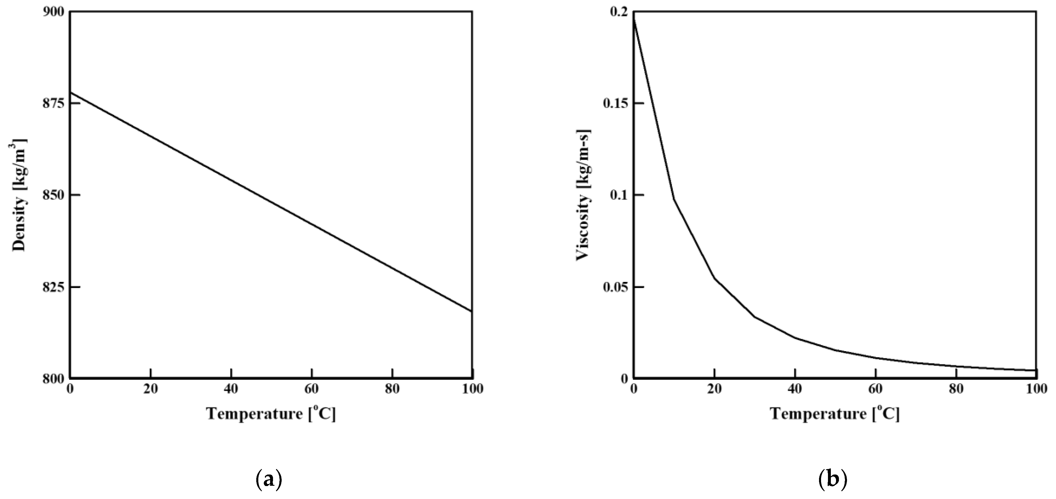
2.2. Numerical Analysis

A numerical analysis was performed to compare the various types of spray nozzles. To analyze the oil flow, we used the Moving Particle Simulation (MPS) method. ParticleWorks® was used for the analysis. The continuum equation (mass conservation law) and Navier–Stokes equations (momentum conservation law) were used as the fundamental governing equations of the MPS method:
/Dt = 0
Du/Dt = −∇P/ρ + ν2u + g + ∇ϕ
where Dρ/Dt represents a Lagrangian derivation, ρ represents the density, u represents the velocity, P represents the pressure, ν is the kinematic viscosity coefficient, and g represents the gravitational acceleration. In the fluid analysis, the surface tension potential model (∇ϕ) was used.
As the cooling oil, ATF SP-IV—an automatic-transmission oil—was used. Figure 2 presents the changes in the oil properties according to the temperature. Figure 2a shows the oil density with respect to the temperature, and Figure 2b shows the oil viscosity with respect to the temperature. These oil properties are the important factors for analyzing the oil flow because they vary significantly with respect to the temperature. The density varies linearly with respect to the temperature; a higher temperature corresponds to a lower density. The viscosity of the oil decreased rapidly until the temperature reached 50 °C, after which it became gentle.
ρ(T) = −0.5988T + 1042
μ(T) = 2 × 10⁻¹³T6 4 × 10⁻¹⁰T5 + 4 × 10⁻⁷T4 0.0002T3 + 0.54T2 8.2514T + 522.74
Equations (3) and (4) give the oil density and viscosity, respectively, as polynomial functions of the temperature T. The analysis was conducted with consideration of the oil properties that vary with respect to the temperature.

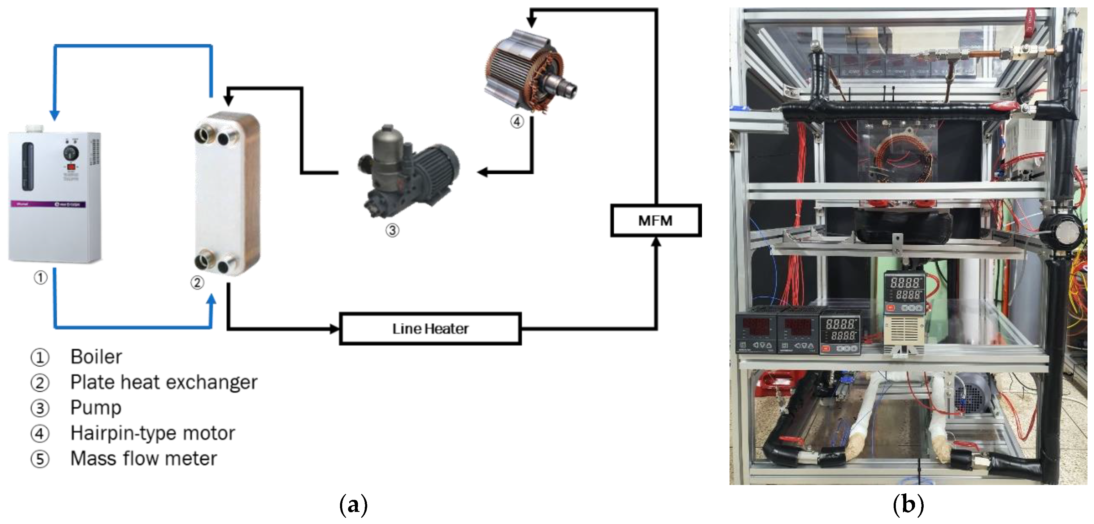
2.3. Experimental Setup

The experimental equipment for the flow-visualization experiment of the motor is shown in Figure 3. The motor used in the experiment is shown in Figure 1b. The cooling oil was transferred to the motor using an oil pump (TOP-210 HBE, DH PUMP Engineering Co., Gimhae-si, Korea). To control the temperature of the oil supplied, heat supplied by a boiler (Kiturami Electric Boiler, Kiturami, Cheongdo County, Korea) was transferred to the oil through a heat exchanger. In an electric vehicle, as the motor is heated, the motor is cooled with the oil temperature of 80 °C. The experiment in this paper is a motor flow visualization experiment, and since no heat is generated in the motor, the oil temperature does not rise. Therefore, we used a boiler to control the oil temperature. The temperature was precisely controlled using a line heater. The oil flow rate was measured using a flowmeter (KTR-550-MF-T-Ex, Korea Flowmeter Ind. Co., Gunpo-shi, Korea), and the oil pump was controlled by an inverter (SV022iG5A-2, LS Electric Co., Anyang-si, Korea) to set the oil flow rate. The transferred oil was sprayed by a nozzle onto the end winding of the coil and was sprayed directly onto the crown and welded parts.

3. Results and Discussion

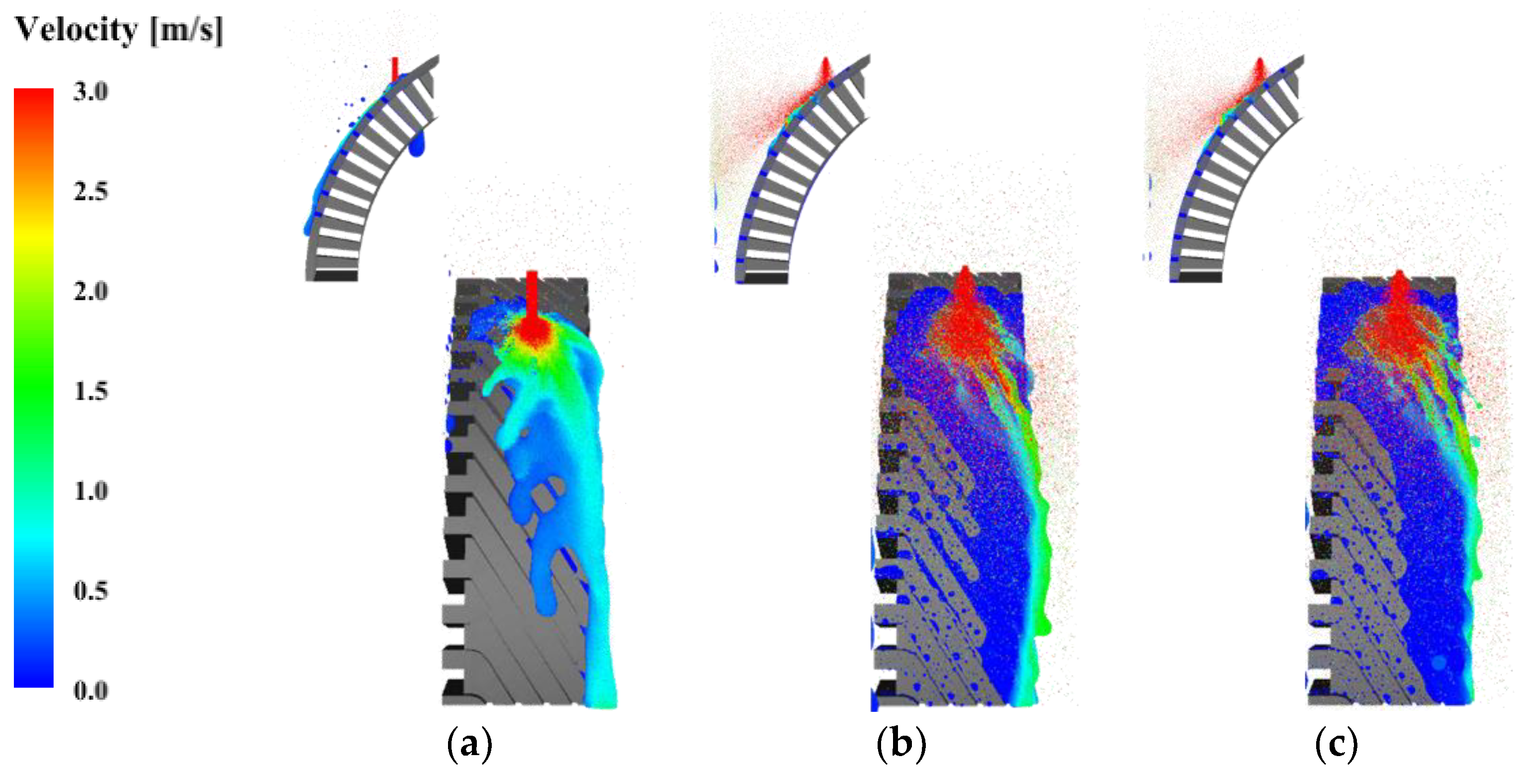
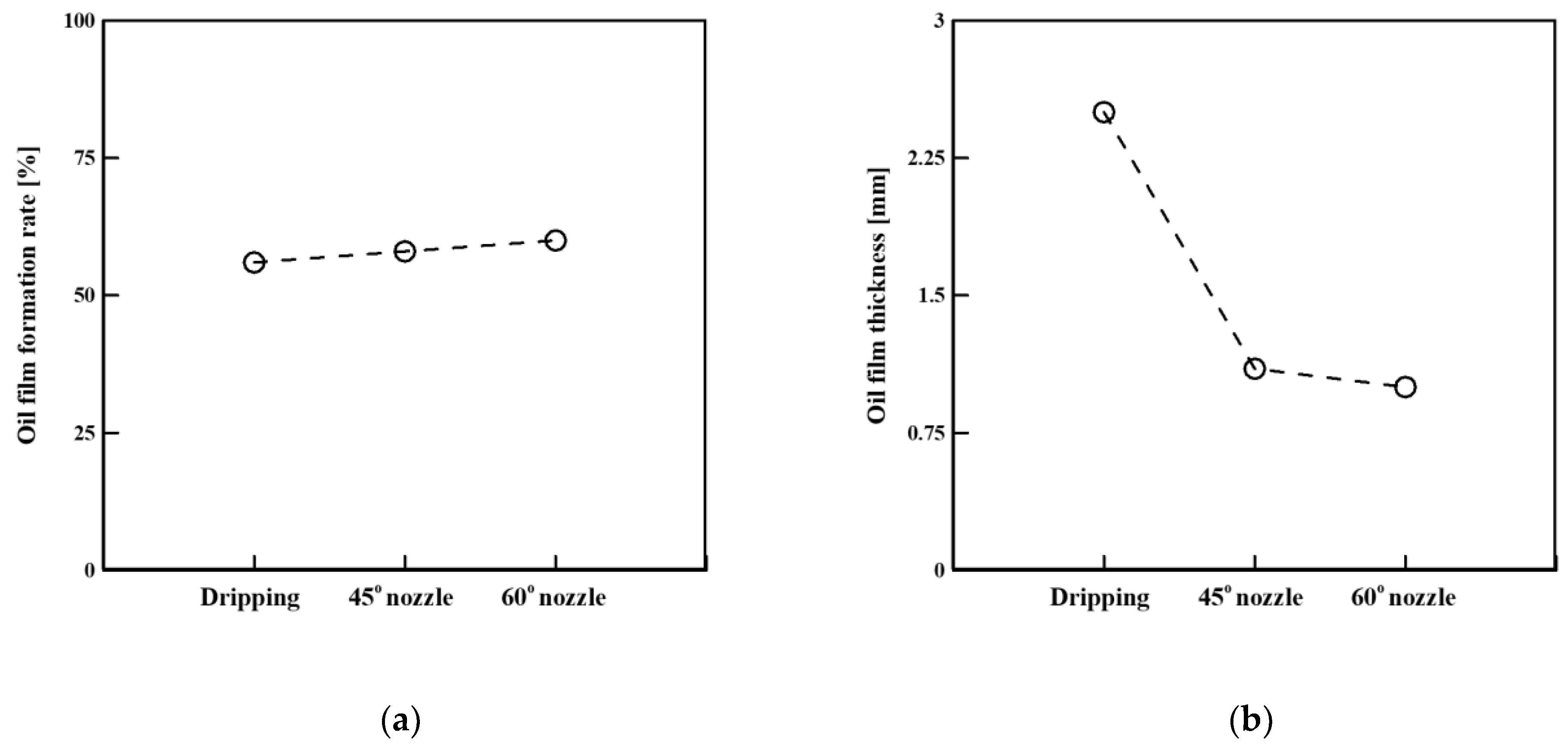
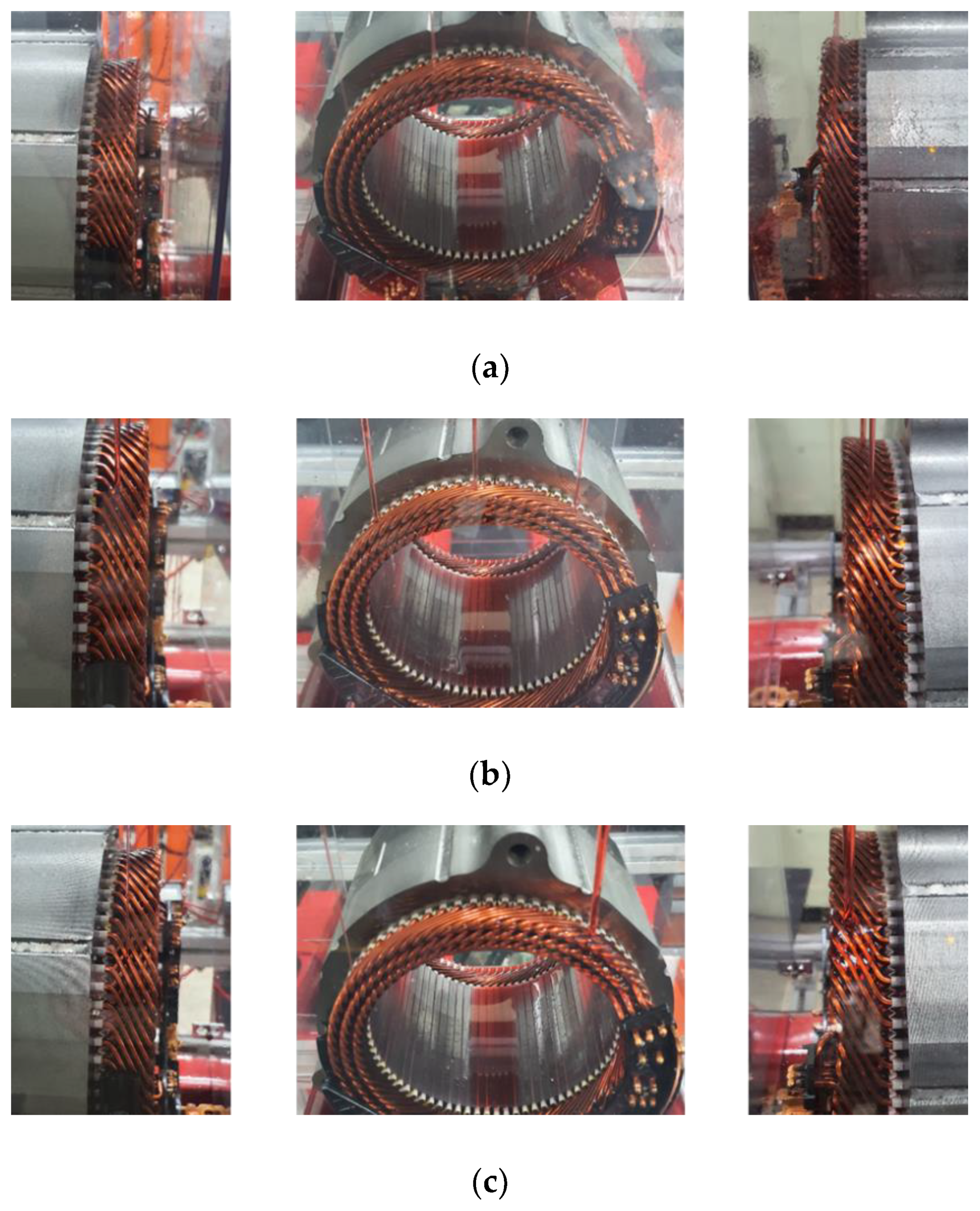
3.1. Effect of Spray Nozzle on Flow Field

Because of the insulating paper between the end windings of the welded part, the oil did not pass between the coils and the oil film was evenly formed. In contrast, the crown part had an empty space between the coils; thus, oil passed through it. The oil flow in the crown part was more difficult to analyze than that in the welded part. Therefore, we studied the formation of the oil film by analyzing the oil flow in the crown part. A numerical analysis was conducted to investigate the effect of the spray-nozzle type on the flow field. The spray nozzles examined included a dripping nozzle and 45° and 60° full-cone nozzles. The full-cone nozzles had significant oil splashing; thus, it was difficult to observe directly in the experiment. To compare the exact oil flow field and the amount of oil splashing, we used the analytical method. Figure 4 shows the flow field and oil velocity in the front and cross sections of the coil. In front of the coil, the flow fields of the three nozzles were similar. The oil flowed in the oblique direction of the coil owing to the coil shape. Figure 4a shows the oil flow with the dripping nozzle. The oil flowed well along the outer surface of the coil, and the oil did not splash after hitting the coil. Additionally, the oil film formed on the coil was thicker than those for the other nozzles. Figure 4b,c shows the oil flow for the 45° and 60° full-cone nozzles. A larger spray angle corresponded to a wider area over which the oil was sprayed onto the coil. However, in contrast to the dripping nozzle, a large amount of oil splashed after hitting the coil. This is because the oil inlet velocity was high. To accurately compare the amounts of oil splashing and the flow through the coil, the results were quantified according to the width and thickness of the oil film. The oil film formation rate was used to quantify the oil film formed on the coil. It was defined as the area where the oil film was formed to the total surface area of the coil. The oil film formation rate Roilfilm is given as follows:
Roilfilm = Aoil/Acoil
where Acoil represents the total surface area of the coil, and Aoil represents the contact area between the coil and the oil.
Q = kA ∙ ∆T
Q = Cm ∙ ∆T
Figure 5a shows the oil film formation rate and Figure 5b shows the oil film thickness. The dripping nozzle and 45° and 60° full-cone nozzles had oil film formation rates of 56%, 58% and 60%, respectively. The nozzles had similar oil film formation rates and flow fields. This is because the oil flow was affected by the coil shape. The oil film thickness of the full-cone nozzles was approximately 1 mm. The oil film thickness of the dripping nozzle was 2.5 mm (approximately 2.5 times larger than that of the full-cone nozzles). The dripping nozzle had the thickest oil film. The full-cone nozzles sprayed the oil more widely than the dripping nozzles, increasing the oil film formation rate. However, they did not form a thick oil film because of the large amount of oil that splashed after hitting the coil. In contrast, the dripping nozzle had little oil splashing and formed the thickest oil film. According to Equation (6), the cooling performance is proportional to the contact area between the oil and the coil. According to Equation (7), the cooling performance is proportional to the contact capacity between the oil and the coil. The area of the oil film was proportional to the amount of heat transferred, and the thickness of the oil film was proportional to the heat capacity. Thus, the use of the dripping nozzle increases the heat capacity, and this nozzle is optimal for motor cooling.

3.2. Effect of Inlet Diameter and Number of Inlets on Flow Field

The foregoing analysis indicated that among the nozzle types considered, the dripping nozzle is most effective for oil injection. An experimental study was conducted to optimize the diameter and number of inlets. The oil temperature was 60 °C, and the flow rate was 1 LPM. The oil was sprayed through the dripping nozzle. Figure 6 shows the experimental results for the oil film formation rate. We waited until the flow field of oil reached dynamic equilibrium and took photographs. Then, we calculated the exact area of each area using the photograph. Through the comparison with numerical analysis, the results of oil film formation rate obtained by calculation using photographs and the numerical results are 3% of error. First, for the same diameter, the effect of the number of inlets on the oil film formation rate was examined. When the inlet diameter was 3.175 mm, the oil film formation rate increased with the number of inlets. The oil inlet velocity varied with respect to the number of inlets. When the number of inlets was 8, 6 and 4, the velocity was 0.527, 0.351 and 0.263 m/s, respectively. A smaller number of inlets corresponded to a higher oil inlet velocity. Consequently, the oil film did not form well. For the inlet diameter of 6.35 mm, the most uniform oil film was formed when the number of inlets was 6. In contrast to the other conditions, the inlets were located at the left, right and middle; thus, the oil was sprayed evenly. The oil flow rate was low (0.088 m/s); thus, there was no oil splashing. Consequently, the oil film was formed evenly throughout the coil. When the inlet diameter was 9.525 mm, the oil film formation rate decreased as the number of inlets increased. The oil inlet rate was the lowest (0.029–0.059 m/s) for this diameter, with no oil splashing. However, owing to the wide inlets, the amounts of oil injected were not identical among the inlets. As the number of inlets increased, the amounts of oil injected at the inlets became more unbalanced, making it difficult to form the oil film. Figure 7 shows experimental photographs taken when the oil film was well formed for each inlet diameter. Figure 7a presents the experimental results for the inlet diameter of 3.175 mm and 8 inlets. Oil splashing occurred on the wall because the oil velocity was 4–9 times faster than those for the other inlet diameters. Figure 7b presents the experimental results for the inlet diameter of 6.35 mm and 6 inlets. As shown, the oil was sprayed evenly at each inlet. Additionally, in contrast to the other inlet-number conditions, the inlets were located at the left, right and middle; thus, the oil was evenly sprayed throughout the coil. Figure 7c shows the experimental results for the inlet diameter of 9.525 mm and 4 inlets. The oil inlet velocity was the lowest for this condition; thus, there was no oil splashing. However, the amount of oil injected was not constant, owing to the large inlet diameter. Thus, when the inlet diameter was 6.35 mm and the number of inlets was 6, the oil film formation rate was 53%, and the oil film formation was optimal.

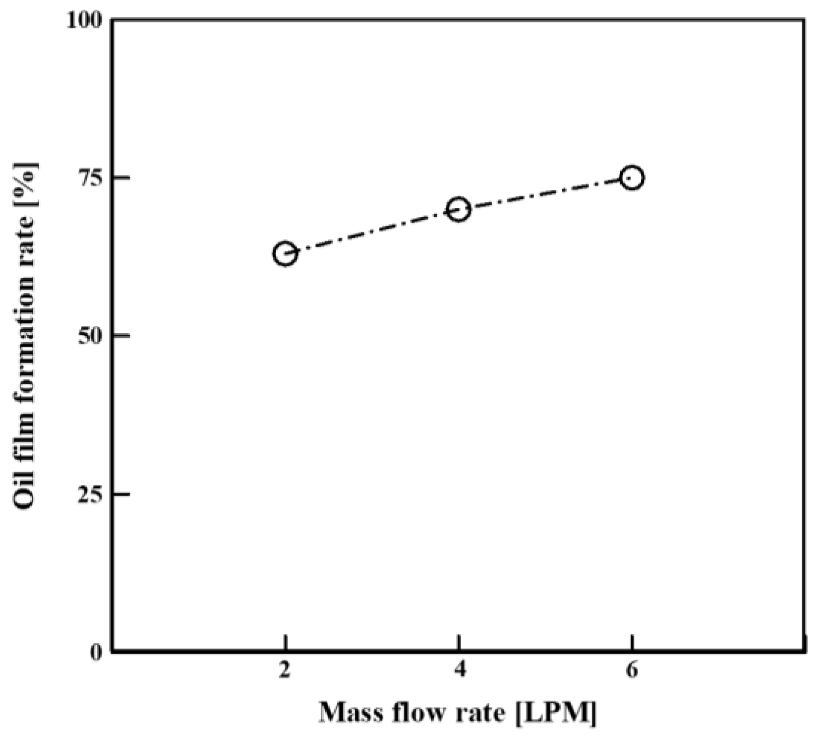
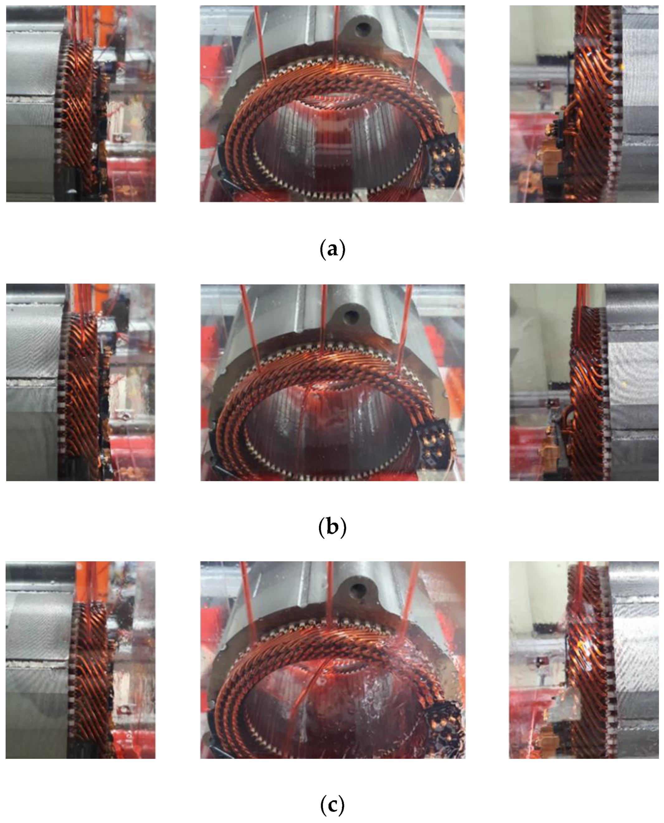
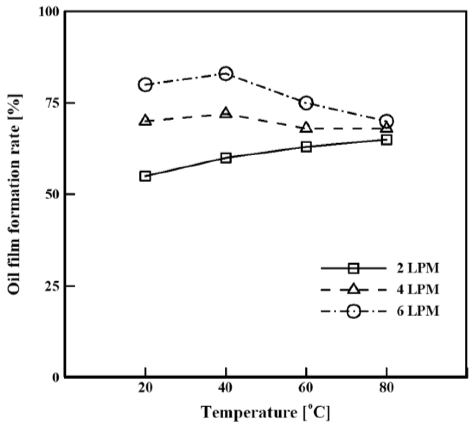
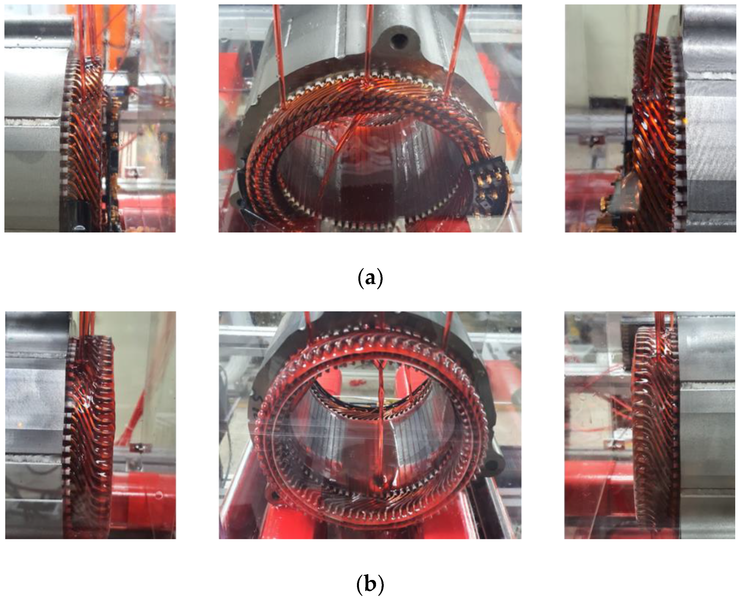
3.3. The Effects of Oil Flow Rate on Flow Field

The use of six dripping nozzles with a diameter of 6.35 mm at the inlet yielded the optimal formation of the oil film. According to the given inlet geometry, the effect of the oil flow rate on the flow field was analyzed experimentally. The temperature of the oil was 60 °C. Figure 8 shows the experimental results for the oil film formation rate. The error of the oil film formation rate was approximately 4.6%. The oil film formation rate was the lowest (63%) when the oil flow rate was 2 LPM. When the oil flow rate was 4 LPM, the oil film formation rate was 70% (7% higher than that at 2 LPM). When the oil flow rate was 6 LPM, the oil film formation rate was 75% (approximately 5% higher than that at 4 LPM), which was the highest rate observed in the experiment. As the oil flow rate increased, the oil film formation rate increased. However, the increase in the oil film formation rate gradually decreased as the flow rate increased.
Figure 9 shows the flow-visualization experiment results for each oil flow rate. Figure 9a shows the oil flow when the oil flow rate was 2 LPM. The oil inlet velocity was 0.176 m/s, which was lower than those of the other flow-rate conditions, because the flow rate was low. Little oil splashing occurred after the oil was sprayed onto the coil, and the oil flowed well along the coil. Figure 9b shows the oil flow when the oil flow rate was 4 LPM. Even at 4 LPM, the oil inlet velocity was low (0.351 m/s); thus, there was almost no oil splashing. However, because the amount of oil increased, the oil flowed downward between the coils. This oil did not flow along the coils but was sprayed onto the lower coil to form the oil film. Compared with the case of 2 LPM, the formation of the oil film was better, because the flow rate was higher. Figure 9c shows the oil flow when the flow rate was 6 LPM. The oil inlet velocity at 6 LPM was 0.527 m/s, which was three times higher than that at 2 LPM. As the oil flow rate increased, oil splashing occurred on the wall. Additionally, the amount of oil that flowed downward between the coils increased. This oil formed a film on the lower coil. As the flow rate increased, the amount of oil splashing increased; however, the amount of oil forming the oil film also increased. Thus, the oil film formation improved with the increase in the oil flow rate and was optimized at 6 LPM.

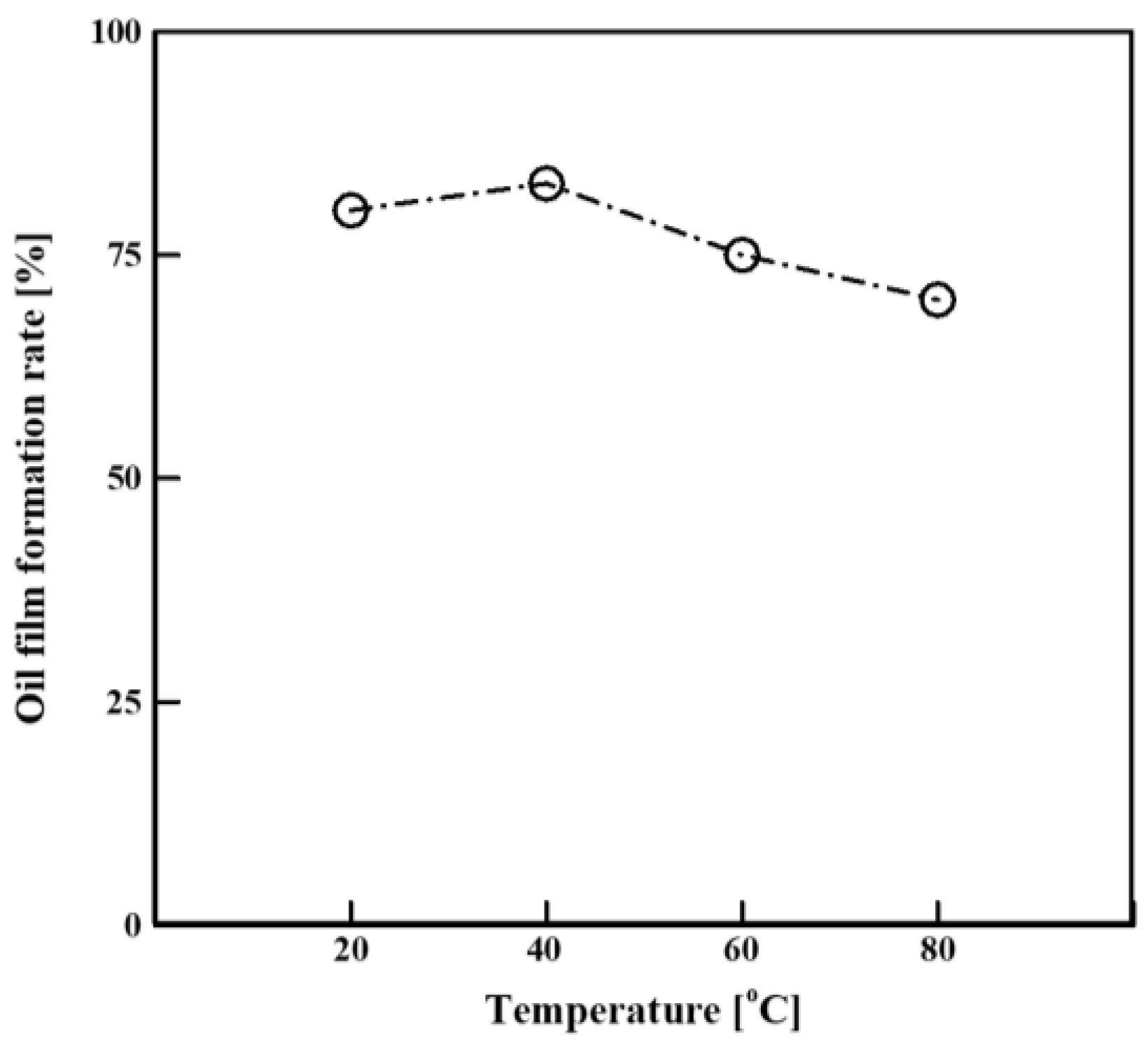
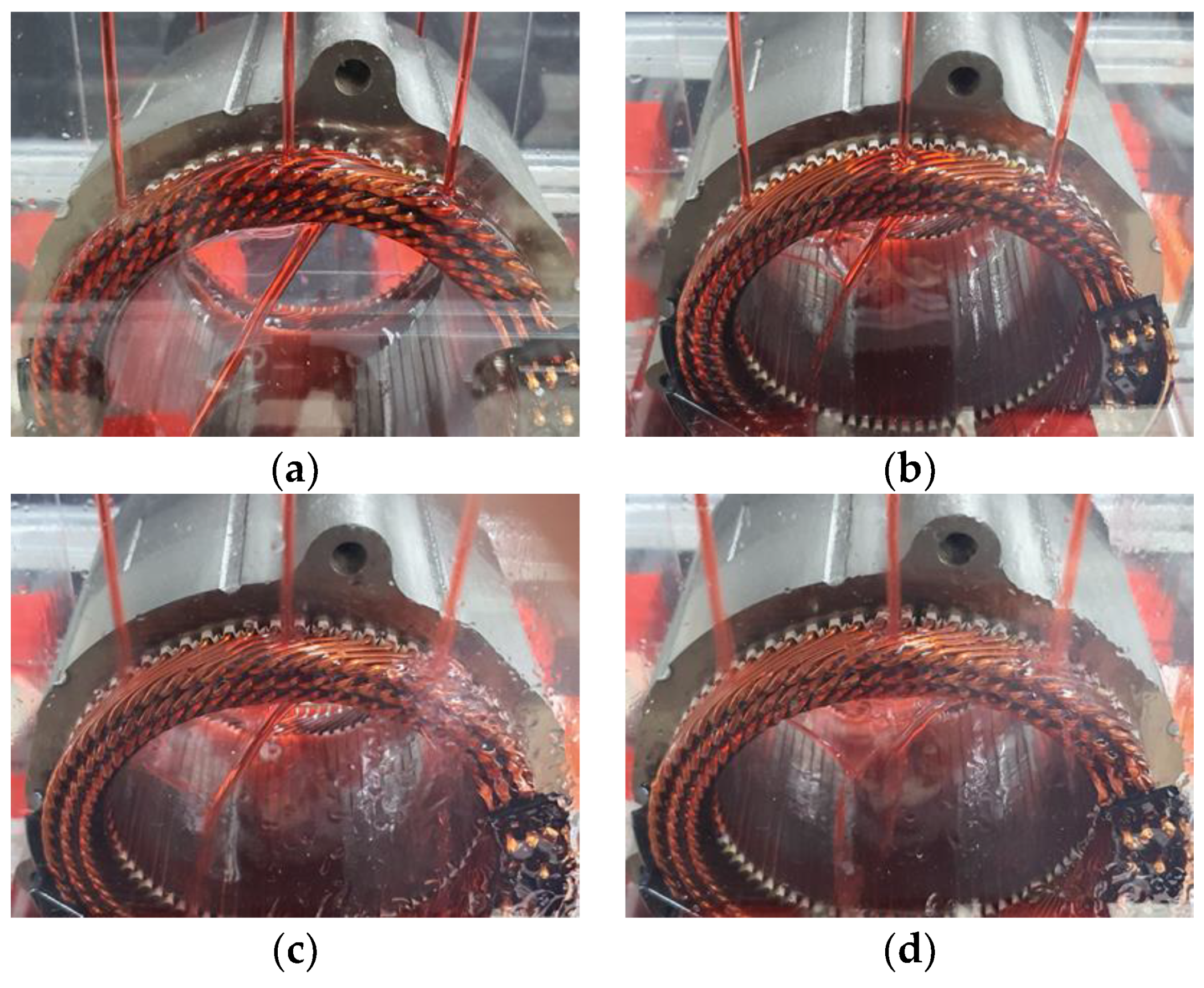
3.4. Effect of Oil Temperature on Flow Field

The viscosity of oil changes rapidly with changes in the temperature; thus, it was important to investigate the effect of the oil temperature on the oil flow. An experiment was conducted to examine the effect of the oil temperature on the flow field. Figure 10 shows the experimental results for the oil film formation rate at a flow rate of 6 LPM. The error of the oil film formation rate was approximately 4%. When the oil temperature was 20 °C, the oil film formation rate was 80%. The oil film formation rate was the highest (83%) at 40 °C. The oil film formation rate at 60 °C was 75%, which was 8% lower than that at 40 °C. The oil film formation rate was the lowest (70%) at 80 °C. The oil film formation rate depended on the temperature. When the temperature increased beyond 40 °C, the oil film formation rate decreased, and the reduction rate was the highest between 40 and 60 °C.
Figure 11a shows the results for an oil temperature of 20 °C. At 20 °C, the oil viscosity was 0.0547 kg/m·s. Owing to the high viscosity, almost no oil splashed after hitting the coil. Additionally, the oil flowed well along the coil. The oil film was formed on the outer surface of the coil; however, the oil film was not well formed between the coils. Figure 11b shows the results for an oil temperature of 40 °C. At 40 °C, the oil viscosity was 0.0222 kg/m·s (approximately 2.5 times lower than that at 20 °C). However, the oil was still very viscous; thus, little oil splashed, and the oil flowed well along the coil. Compared with the case of 20 °C, the oil film was thinner but more uniform. Figure 11c,d show the results for oil temperatures of 60 and 80 °C, respectively. The oil viscosities at these temperatures were 0.0113 and 0.0067 kg/m·s, respectively. As the temperature increased, the viscosity of the oil decreased, and the amount of oil that splashed after hitting the coil increased. At 80 °C, more oil splashed compared with 60 °C, and a large amount of oil was lost. Thus, when the oil flow rate was 6 LPM, the oil film was optimal at the oil temperature of 40 °C.

3.5. Studied Oil Injection Method

The correlation between the oil flow rate and the temperature on the oil film formation rate was analyzed. Figure 12 shows the oil film formation rate under each oil condition. When the oil temperature increased at the same flow rate, the oil film formation rate was significantly affected by the viscosity of the oil. When the oil flow rate was 2 LPM, the oil inlet velocity was low; thus, little oil splashed after hitting the coil. There was no oil splashing even when the viscosity was reduced; thus, a higher temperature corresponded to a higher oil film formation rate. In contrast, when the oil flow rate was >4 LPM, the formation of the oil film was optimal at 40 °C. When the oil temperature was 20 °C, the viscosity was high, and the oil film was thick. When the oil temperature was 40 °C, the oil film was thinner but more uniform than that at 20 °C. When the oil temperature was >60 °C, the oil viscosity decreased significantly; thus, the amount of oil that splashed after hitting the coil increased, reducing the oil film formation rate. The oil film formation rate increased with the flow rate, regardless of the oil temperature. The viscosity of the oil at 20 and 40 °C was high; thus, even when the flow rate increased, there was no oil splashing, and the oil film was well formed. In contrast, the viscosity at 80 °C was very low; thus, as the flow rate increased, the oil inlet velocity increased, and the amount of splashing oil increased. Therefore, even when the flow rate increased, the oil film formation rate did not increase significantly. Accordingly, the formation of the oil film was optimal when the oil temperature was 40 °C and the flow rate was 6 LPM.
Figure 13 and Figure 14 show the results of applying the oil-cooling method with the optimized oil injection conditions. A dripping nozzle was used as the spray nozzle, and the inlet diameter and number of inlets were 6.35 mm and 6, respectively. The nozzles were located at the top of the end winding of the coil, and the crown and welded parts each had three nozzles. At each part, the nozzles were placed at the left, right, and middle sides of the coil. The inlet oil temperature and flow rate were 40 °C and 6 LPM, respectively. Figure 13a shows the oil flow in the crown part. No oil splashed after hitting the coil, and the oil flowed well along the coil. The oil flow was affected by the diagonal direction of the coil. The oil film formation rate was 83%. Figure 13b shows the oil flow in the welded part. Here, the oil flowed well, without splashing. In contrast to the crown part, the welded part had insulating paper between the coils. Because of the insulating paper, the oil film was formed more evenly than that in the crown part. The oil film formation rate was 90% for the welded part (7% higher than that for the crown part). Figure 14 shows the results of the numerical analysis of the crown part, which support the results in Figure 13a and provide details regarding the oil flow over the coil. The oil flow was similar between the two cases; however, there was a slight difference due to the simplification of the geometry. Figure 14a,c shows the oil flow at the right and left nozzles, respectively. The oil flowed well along the oblique direction of the coil, without splashing. As the oil flowed downward, it was evenly distributed on the coil. Figure 14b shows the oil flow at the middle nozzle. The oil flowed along the coil without splashing. However, in contrast to the actual situation, there was no empty space between the coils; thus, no oil passed through.

4. Conclusions

The oil injection method was studied to maximize the cooling performance of an electric-vehicle motor using a hairpin winding. The Chevrolet Bolt EV motor (Chevrolet, Detroit, MI, USA), which uses a hairpin winding, was selected as the target motor. To maximize the cooling performance of the motor, the oil must be evenly distributed, because the amount of heat transfer is proportional to the contact area between the oil and the coil. Therefore, analyses and experiments were performed to investigate the effects of various conditions on the formation of the oil film. Finally, the geometry and conditions of the inlet were studied for maximizing the width of the oil film.
First, a numerical analysis was conducted to compare different types of spray nozzles. When 45° and 60° full-cone nozzles were used, the oil was sprayed widely and formed a wide film. However, the oil film was as thin as 1 mm, because a large amount of oil splashed after hitting the coil. A dripping nozzle formed an oil film similar to that for the full-cone nozzles. However, the oil film had a thickness of 2.5 mm. Thus, the use of the dripping nozzle increased the heat capacity, and this nozzle is the best type for cooling.
Subsequently, an experiment was conducted to analyze the effects of the number of dripping nozzles and the nozzle diameter on the oil flow. A smaller inlet diameter corresponded to a higher oil inlet velocity and a larger amount of splashed oil. With an increase in the inlet diameter, the oil flow rates at the different inlets differed, resulting in a non-uniform oil film. When the inlet diameter was 3.175 mm, the oil film formation rate decreased as the number of inlets decreased. This is because the oil inlet velocity increased when the number of inlets decreased. Consequently, the amount of oil that splashed after hitting the coil increased. When the inlet diameter was 9.525 mm, the oil film formation rate decreased as the number of inlets increased. This is because the inlets were wide, and the oil flow rates differed among the inlets. Lastly, in the case of the 6.35 mm inlet diameter, the formation of the oil film was optimal (oil film formation rate of 53%) when the number of inlets was six.
Next, an experiment was conducted to analyze the effects of the oil temperature and flow rate on the oil flow for the studied inlet geometry. As the flow rate increased, the oil inlet velocity increased. Consequently, the amounts of oil that splashed and flowed downward through the coils increased. The oil that flowed downward between the coils was sprayed onto the lower coil to form the oil film. Thus, the formation of the oil film was improved when the oil flow rate increased. The viscosity of the oil changed rapidly as the temperature increased. When the oil temperature was 20 °C, the viscosity was high, and the oil film was thick. When the oil temperature was 40 °C, the oil film was thinner but more uniform than that at 20 °C. When the oil temperature reached >60 °C, the viscosity of the oil decreased significantly, and the amount of oil that splashed after hitting the coil increased. Thus, the formation of the oil film was optimal (oil film formation rate of 83%) when the oil temperature was 40 °C and the flow rate was 6 LPM.
To form the widest oil film, the dripping nozzle was used as the spray nozzle, and the inlet diameter and number of inlets were 6.35 mm and 6, respectively. The inlet oil temperature and flow rate were 40 °C and 6 LPM, respectively. In an experiment, the optimized oil injection method was applied, and the flow field and formation of the oil film in the crown and welded parts were analyzed. In the crown part, no oil splashed after hitting the coil, and the oil flowed well along the coil. The oil film formation rate was 83%. The oil film was formed more evenly in the welded part than in the crown part owing to the insulating paper between the coils. The oil film formation rate was 90% in the welded part. Thus, we studied the oil injection method for cooling high-performance electric-vehicle motors with hairpin windings. The results of this paper provide important information for the development and research of high-performance electric vehicle motors. Furthermore, we will do more research to apply the oil cooling method to a hairpin type motor based on the results of this paper.

Author Contributions

Conceptualization, T.H.; methodology, T.H.; validation, T.H.; formal analysis, T.H.; investigation, T.H.; writing—original draft preparation, T.H.; writing—review and editing, T.H. and D.K.K.; All authors have read and agreed to the published version of the manuscript.

Funding

This research received no external funding.

Institutional Review Board Statement

Not applicable.

Informed Consent Statement

Not applicable.

Acknowledgments

This work was also supported by the Korea Institute of Energy Technology Evaluation and Planning (KETEP) and the Ministry of Trade, Industry and Energy (MOTIE) of the Republic of Korea (No. 20206810100030), (No.20008021).

Conflicts of Interest

The authors declare no conflict of interest.

References

  1. Emadi, A.; Lee, Y.J.; Rajashekara, K. Power electronics and motor drives in electric, hybrid electric, and plug-in hybrid electric vehicles. IEEE Trans. Ind. Electron. 2008, 55, 2237–2245. [Google Scholar] [CrossRef]
  2. Cezário, C.A.; Verardi, M.; Borges, S.S.; Silva, J.C.; Oliveira, A.A.M. Transient Thermal Analysis of an Induction Electric Motor. In Proceedings of the 18th International Congress of Mechanical Engineering, Ouro Preto, Brazil, 6–11 November 2005; pp. 1–8. [Google Scholar]
  3. Mi, C.; Slemon, G.R.; Bonert, R. Modeling of iron losses of permanent-magnet synchronous motors. IEEE Trans. Ind. Appl. 2003, 39, 734–742. [Google Scholar] [CrossRef]
  4. Fakhfakh, M.A.; Kasem, M.H.; Tounsi, S.; Neji, R. Thermal Analysis of a Permanent Magnet Synchronous Motor for Electric Vehicles. J. Asian Electr. Veh. 2008, 6, 1145–1151. [Google Scholar] [CrossRef]
  5. Cavazzuti, M.; Gaspari, G.; Pasquale, S.; Stalio, E. Thermal management of a Formula E electric motor: Analysis and optimization. Appl. Therm. Eng. 2019, 157, 113733. [Google Scholar] [CrossRef]
  6. Fan, J.; Zhang, C.; Wang, Z.; Dong, Y.; Nino, C.E.; Tariq, A.R.; Strangas, E.G. Thermal Analysis of Permanent Magnet Motor for the Electric Vehicle Application Considering Driving Duty Cycle. IEEE Trans. Magn. 2010, 46, 2493–2496. [Google Scholar] [CrossRef]
  7. Ding, X.; Bhattacharya, M.; Mi, C. Simplified Thermal Model of PM Motors in Hybrid Vehicle Applications Taking into Account Eddy Current Loss in Magnets. J. Asian Electr. Veh. 2010, 8, 1337–1343. [Google Scholar] [CrossRef] [Green Version]
  8. Gai, Y.; Kimiabeigi, M.; Chuan Chong, Y.; Widmer, J.D.; Deng, X.; Popescu, M.; Goss, J.; Staton, D.A.; Steven, A. Cooling of automotive traction motors: Schemes, examples, and computation methods. IEEE Trans. Ind. Electron. 2019, 66, 1681–1692. [Google Scholar] [CrossRef] [Green Version]
  9. Carriero, A.; Locatelli, M.; Ramakrishnan, K.; Mastinu, G.; Gobbi, M. A Review of the State of the Art of Electric Traction Motors Cooling Techniques; SAE Technical Papers; SAE International: Warrendale, PA, USA, 2018; Volume 2018. [Google Scholar] [CrossRef]
  10. Kim, C.; Lee, K.S.; Yook, S.J. Effect of air-gap fans on cooling of windings in a large-capacity, high-speed induction motor. Appl. Therm. Eng. 2016, 100, 658–667. [Google Scholar] [CrossRef]
  11. Kim, M.S.; Lee, K.S.; Um, S. Numerical investigation and optimization of the thermal performance of a brushless DC motor. Int. J. Heat Mass Transf. 2009, 52, 1589–1599. [Google Scholar] [CrossRef]
  12. Kim, C.; Lee, K.S. Numerical investigation of the air-gap flow heating phenomena in large-capacity induction motors. Int. J. Heat Mass Transf. 2017, 110, 746–752. [Google Scholar] [CrossRef]
  13. Momen, F.; Rahman, K.; Son, Y.; Savagian, P. Electrical propulsion system design of Chevrolet Bolt battery electric vehicle. In Proceedings of the IEEE Energy Conversion Congress and Exposition (ECCE), Milwaukee, WI, USA, 18–22 September 2016. [Google Scholar] [CrossRef]
  14. Ye, Z.N.; Luo, W.D.; Zhang, W.M.; Feng, Z.X. Simulative analysis of traction motor cooling system based on CFD. In Proceedings of the International Conference on Electric Information and Control Engineering, ICEICE 2011, Wuhan, China, 15–17 April 2011; pp. 746–749. [Google Scholar] [CrossRef]
  15. Pechanek, R.; Bouzek, L. Analyzing of two types water cooling electric motors using computational fluid dynamics. In Proceedings of the 15th International Power Electronics and Motion Control Conference (EPE/PEMC), Novi Sad, Serbia, 4–6 September 2012; pp. 2–6. [Google Scholar] [CrossRef]
  16. Rehman, Z.; Seong, K. Three-D numerical thermal analysis of electric motor with cooling jacket. Energies 2018, 11, 92. [Google Scholar] [CrossRef] [Green Version]
  17. Liu, M.; Li, Y.; Ding, H.; Sarlioglu, B. Thermal management and cooling of windings in electrical machines for electric vehicle and traction application. In Proceedings of the 2017 IEEE Transportation Electrification Conference and Expo (ITEC), Chicago, IL, USA,, 22–24 June 2017; pp. 668–673. [Google Scholar] [CrossRef]
  18. Huang, Z.; Nategh, S.; Lassila, V.; Alaküla, M.; Yuan, J. Direct oil cooling of traction motors in hybrid drives. In Proceedings of the 2012 IEEE International Electric Vehicle Conference, Greenville, SC, USA, 4–8 March 2012. [Google Scholar]
  19. Ponomarev, P.; Polikarpova, M.; Pyrhönen, J. Thermal modeling of directly-oil-cooled permanent magnet synchronous machine. In Proceedings of the 20th International Conference on Electrical Machines, ICEM 2012, Marseille, France, 2–5 September 2012; pp. 1882–1887. [Google Scholar]
  20. Davin, T.; Pellé, J.; Harmand, S.; Yu, R. Experimental study of oil cooling systems for electric motors. Appl. Therm. Eng. 2015, 75, 1–13. [Google Scholar] [CrossRef]
  21. Jung, D.S.; Kim, Y.H.; Lee, U.H.; Lee, H.D. Optimum design of the electric vehicle traction motor using the hairpin winding. In Proceedings of the IEEE Vehicular Technology Conference, Yokohama, Japan, 6–9 May 2012. [Google Scholar]
Figure 1. Target motor: (a) CAD geometry; and (b) motor to be tested.
Energies 14 00747 g001
Figure 2. Cooling-oil properties: (a) density; and (b) viscosity.
Energies 14 00747 g002
Figure 3. Experimental equipment: (a) schematic; and (b) photograph.
Energies 14 00747 g003
Figure 4. Cross section of coil: (a) dripping nozzle; (b) full cone nozzle (spray angle: 45°); (c) full cone nozzle (spray angle: 60°).
Energies 14 00747 g004
Figure 5. Oil film for different spray-nozzle types: (a) oil film formation rate; (b) oil film thickness.
Energies 14 00747 g005
Figure 6. Oil film formation rate according to the number and diameter of inlets.
Energies 14 00747 g006
Figure 7. Oil flow according to the number and diameter of inlets: (a) 3.175 mm and 8 inlets; (b) 6.35 mm and 6 inlets; (c) 9.525 mm and 4 inlets.
Energies 14 00747 g007
Figure 8. Oil film formation rate according to the mass flow rate at 60 °C.
Energies 14 00747 g008
Figure 9. Oil flow according to the mass flow rate at 60 °C: (a) 2 LPM; (b) 4 LPM; (c) 6 LPM.
Energies 14 00747 g009
Figure 10. Oil film formation rate according to the temperature at 6 LPM.
Energies 14 00747 g010
Figure 11. Oil flow according to the temperature at 6 LPM: (a) 20 °C; (b) 40 °C; (c) 60 °C; (d) 80 °C.
Energies 14 00747 g011
Figure 12. Oil film formation rate according to the temperature at each mass flow rate.
Energies 14 00747 g012
Figure 13. Overall oil flow at 40 °C, 6 LPM: (a) crown part; and (b) welded part.
Energies 14 00747 g013
Figure 14. Oil flow at each nozzle: (a) right; (b) middle; (c) left.
Energies 14 00747 g014
Publisher’s Note: MDPI stays neutral with regard to jurisdictional claims in published maps and institutional affiliations.

