Article

Experimental Study on Infrared Temperature Characteristics and Failure Modes of Marble with Prefabricated Holes under Uniaxial Compression

1
School of Civil Engineering, Shaoxing University, Shaoxing 312000, China
2
Key Laboratory of Rock Mechanics and Geohazards of Zhejiang Province, Shaoxing 312000, China
3
State Key Laboratory for Geomechanics and Deep Underground Engineering, China University of Mining and Technology (Beijing), Beijing 100083, China
4
School of Earth Sciences and Engineering, Hohai University, Nanjing 210098, China
*
Author to whom correspondence should be addressed.
Energies 2021, 14(3), 713; https://doi.org/10.3390/en14030713
Submission received: 30 December 2020 / Revised: 26 January 2021 / Accepted: 27 January 2021 / Published: 30 January 2021

Abstract

:
In rock engineering, it is of great significance to study the failure mechanical behavior of rocks with holes. Using a combination of experiment and infrared detection, the strength, deformation, and infrared temperature evolution behavior of marble with elliptical holes under uniaxial compression were studied. The test results showed that as the vertical axis b of the ellipse increased, the peak intensity first decreased and then increased, and the minimum value appeared when the horizontal axis was equal to the vertical axis. The detection results of the infrared thermal imager showed that the maximum temperature, minimum temperature, and average temperature of the observation area in the loading stage showed a downward trend, and the range of change was between 0.02 °C and 1 °C. It was mainly due to the accumulation of energy in the loading process of the rock sample that caused the surface temperature of the specimen to decrease. In the brittle failure stage, macroscopic cracks appeared on the surface of the rock sample, which caused the energy accumulated inside to dissipate, thereby increasing the maximum temperature and average temperature of the rock sample. The average temperature increase was about 0.05 °C to about 0.19 °C. The evolution of infrared temperature was consistent with the mechanical characteristics of rock sample failure, indicating that infrared thermal imaging technology can provide effective monitoring for the study of rock mechanics. The research in this paper provides new ideas for further research on the basic characteristics of rock failure under uniaxial compression.

1. Introduction

Deformation and failure of rock is a complex mechanical behavior, and signals such as light, sound, electricity, and magnetism are generated during the failure process. Many scholars have used digital images [1,2,3], acoustic emission [4,5,6], CT [7,8,9], and other technical means to conduct a lot of in-depth research on the process of rock deformation and failure and have obtained a lot of research results.
The process of rock deformation and failure is also a process of energy release. Infrared thermal imaging technology can perform high-frequency, real-time monitoring of the infrared radiation temperature of the rock surface, providing an effective method for rock mechanics’ research. In 1986, Brand and Roswell [10] began to use optical spectroscopy to study the optical radiation characteristics of basalt and granite during uniaxial compression failure, hoping to predict the failure of rocks through related studies on rock electromagnetic wave radiation. At the end of the 20th century, Luong [11,12,13] carried out a series of studies using infrared thermal imaging technology. According to the principle of thermal-mechanical coupling, the infrared heat radiation characteristics of concrete in the process of fatigue damage and stress damage were analyzed. Infrared thermal imaging technology was used to study the process of crack initiation, development, and propagation and to evaluate the damage of concrete. At the beginning of the 21st century, Wu Lixin and his team [14,15,16,17,18,19] carried out a series of systematic rock mechanics’ tests based on infrared thermal imaging technology and tested the discontinuous combination fault rupture, the double-shear stick-slip fault, the stick-slip of the intersection fault, and the rock pressure. The thermal infrared radiation law of shear fracture has been studied and analyzed in detail, and the infrared radiation characteristics and influencing factors of the process of rock stick-slip, rock frictional slip, and rock low-speed impact were also studied. The infrared radiation laws and thermal infrared precursor characteristics of granite, gneiss, quartz sandstone, and other rocks during the stress failure process were explored.
Subsequently, Gong Weili et al. [20,21,22] studied the deformation and failure characteristics of deep soft rock roadways based on infrared thermal imaging technology and revealed the friction and slip phenomenon between rock layers during the deformation and failure process of roadways through infrared images. Zhang Yanbo et al. [23,24] first observed the whole process of uniaxial compression failure of a round hole rock sample with an infrared thermal imaging camera, studied the infrared radiation characteristics of the failure process of the porous rock, and analyzed that regional zonal heating is an important precursor to rock failure. Infrared thermal imaging and acoustic emission technology were used to jointly monitor the failure process of granite samples, and the damage evolution process of the rock was studied from the two perspectives of surface temperature changes and internal acoustic emission characteristics. Wu Xianzhen et al. [25,26] proposed the concept of “Infrared Temperature Variation Field (ITVF)” and conducted an in-depth study on the characteristics of the instantaneous change of the infrared temperature field during the fracture process of saturated siltstone, providing a new method for exploring the precursors of rock fracture. Ma Liqiang et al. [27,28] proposed a new quantitative analysis index of infrared radiation, “differential infrared variance”, and studied the abnormal characteristics of infrared radiation in the process of coal destruction. Zhou Zilong et al. [29] carried out uniaxial compression tests on granite samples under different loading rates, used infrared thermal imaging cameras to monitor the whole process, and studied the infrared radiation characteristics during the failure of the samples. Junwei Ma et al. [30] used infrared thermal imaging technology combined with ground laser scanning and particle tracking velocimetry to study the stability of landslides and showed that the decrease of the average temperature change can be used as a precursor to landslide damage.
In summary, infrared thermal imaging technology has been widely used in rock mechanics’ experiments such as roadways, slopes, and jointed rock masses [31,32,33,34,35]. However, the current infrared experiments are mainly focused on the research of complete models and specimens. The rock mass is usually rich in joints, cracks, and holes, which play a vital role in the stability of the rock mass [36]. Through a series of indoor experiments, researchers have conducted a lot of in-depth research on the failure process of prefabricated joints, cracks, and holes in the rock [37,38,39,40,41,42,43,44], which is of great significance for exploring the failure mechanism of rocks. In this paper, the size of the horizontal axis a of the rock sample elliptical hole remained unchanged and the vertical axis b gradually increased. The ratio of the vertical axis to the horizontal axis k had a significant impact on the failure strength of the rock. An FLIR X8501sc infrared thermal imaging camera was used as the experimental observation equipment to conduct synchronous, high-frequency, real-time observation of the uniaxial compression test of marble to study the evolution characteristics of the temperature field during the failure process of the sample.

2. Experimental

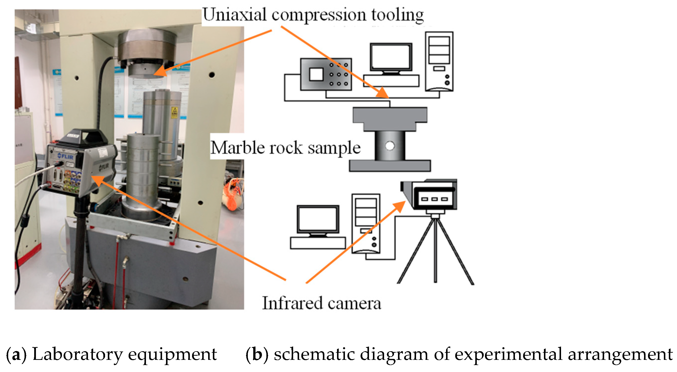
2.1. Testing Machine

This experiment used cylindrical marble as the experimental sample, with a diameter of 50 mm and a height of 50 mm. The non-parallelism and non-perpendicularity of the end faces were both less than 0.02 mm, which met the basic requirements of ISRM. There were four different prefabricated elliptical holes and one round hole in the geometric center of the sample side. The size of the elliptical hole was 12 mm × 4 mm (horizontal axis a × vertical axis b), 12 mm × 8 mm, 12 mm × 16 mm, and 12 mm × 20 mm. The size of the circular hole was 12 mm × 12 mm. There were three samples per group. The uniaxial compression test was carried out with test system for deep rock gas escape under temperature-pressure coupling condition. The loading method was selected as displacement loading, and the loading rate was 0.1 mm/min. At the same time, an infrared thermal imaging camera observation system was set up for synchronous, high-frequency, real-time observation, and the observation rate was 15 frames/s. The sample picture is shown in Figure 1. Uniaxial compression test system-infrared thermal imaging camera monitoring system equipment is shown in Figure 2 below.
From Figure 2 above, it can be seen that the infrared camera could observe the whole process of the experiment during the experiment. The prefabricated hole marble specimen in Figure 1 was placed under the loading head of the equipment to complete the uniaxial compressive strength test.
The FLIR X8501sc infrared thermal imaging camera used in this study had a temperature measurement range of −20 °C~1500 °C, a thermal sensitivity of 0.02 °C, an integration time adjustment range of 0.3 us~30 ms, and a pixel clock of 355 MHz. Infrared heat radiation is easily affected by the surrounding environment. However, the FLIR X8501sc infrared thermal imaging camera uses a refrigerated photon detector and uses indium antimonide (InSb) as the refrigeration material, which is not easily affected by the environment.

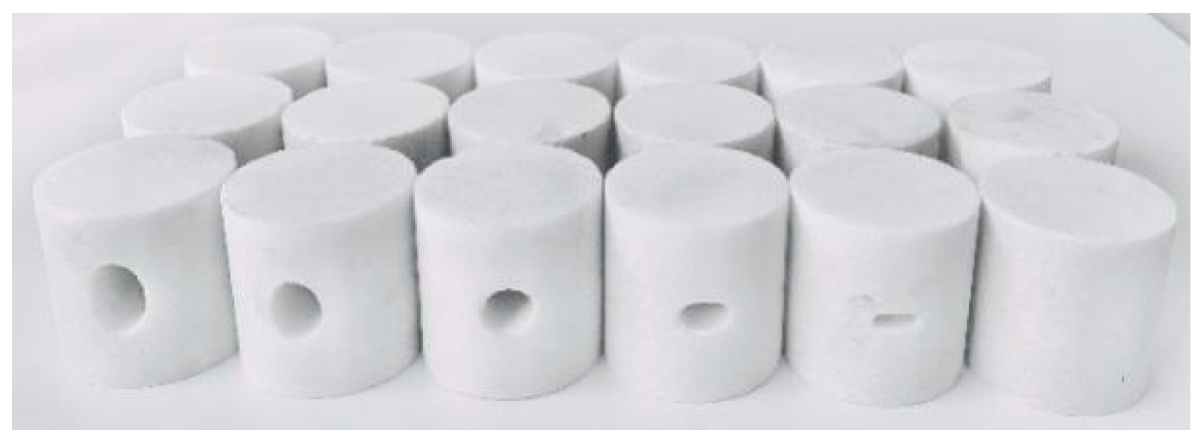
2.2. Testing Program

(1) Fix the FLIR X8501 sc thermal imaging camera on a tripod. Then adjust the tripod to a suitable height and a suitable distance from the observation surface of the specimen. The camera has high temperature measurement accuracy, strong resistance to environmental interference, and can record temperature changes during the entire experiment.
(2) Connect the relevant lines. Then open the software operation interface. Connect the infrared thermal imager. Select the appropriate temperature measurement range. Set the emissivity, atmospheric temperature, storage path and other related parameters. Adjust the camera lens focal length to make the image clear.
(3) Since the infrared thermal imaging camera is very sensitive to heat sources, the external environment and personnel activities will have a great impact on the test results. In order to make the test data more realistic, the experiment was carried out in a closed environment without the influence of people walking and air flow, so as to minimize the environmental impact.
(4) Simultaneously, when the uniaxial compression test is loaded, the data will be collected synchronously at a frame rate of 15 frames/s.
(5) After the test is over, the data collection is completed, and the relevant software is used to analyze the infrared radiation data during the destruction of the sample.

2.3. Principle of Infrared Thermal Imaging

Any object in nature above absolute zero is constantly radiating electromagnetic waves through its own molecular motion. The infrared spectrum is distributed between visible light and microwave, and the wavelength is between 0.75 μm and 1000 μm. Infrared thermal imaging technology actually converts the difference in infrared radiation on the surface of an object into infrared images with different temperature distributions. The infrared thermal imager cannot directly measure the temperature of the surface of the object but measures the infrared radiation energy projected on the detector. The radiant temperature is calculated by the function of radiant energy and temperature. That is, the temperature detected by the infrared camera is actually the radiation temperature.
The working principle of the infrared camera is that the optical system collects the infrared radiation on the sensitive surface of the detector. The scanner matches the small field of view of the detector with the large field of view of the optical system. The signal processing circuit converts infrared radiation into electrical signals and amplifies them. Finally, it is displayed by the monitor in the form of an infrared thermal image.

3. Analysis of Experimental Results

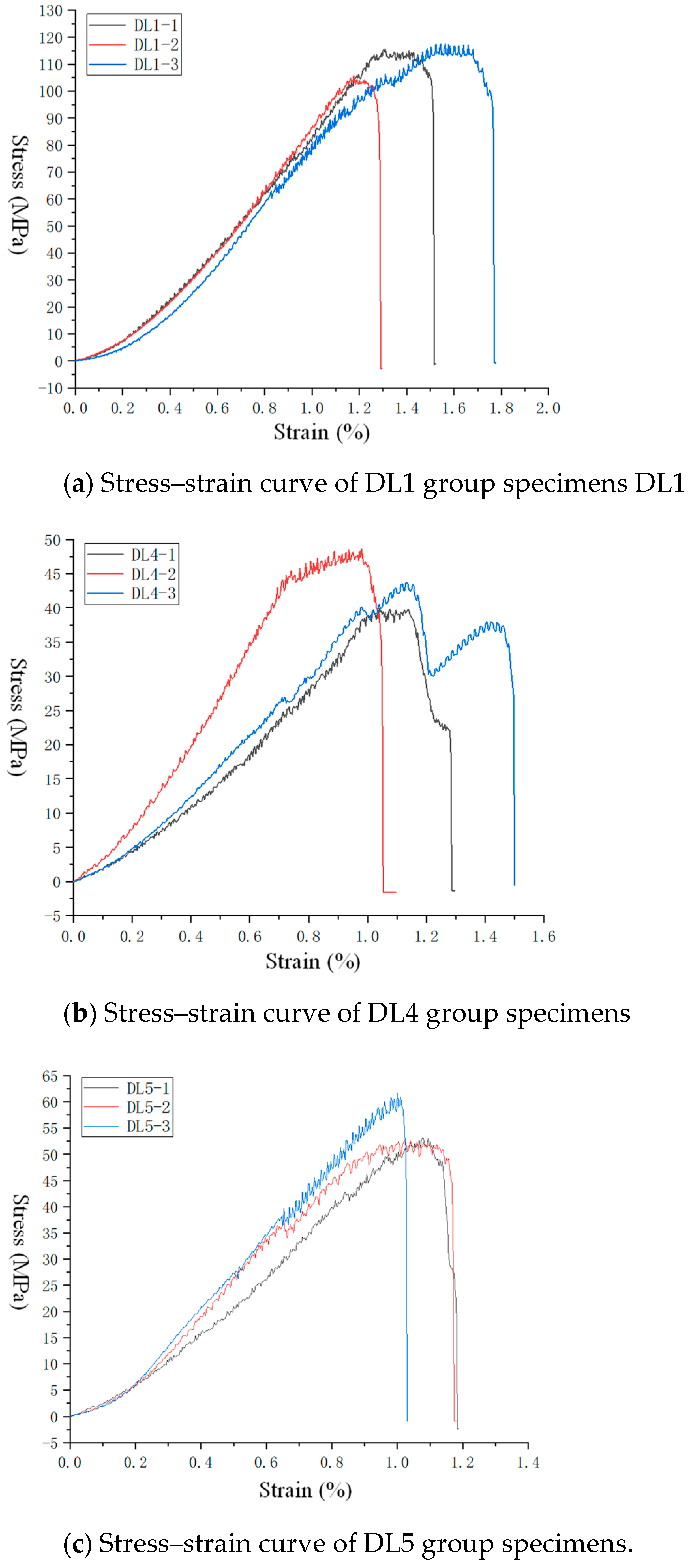
3.1. Stress–Strain Curve

Because the stress–strain curve of DL2 is similar to that of DL1, the stress–strain curve of DL3 is similar to that of DL4 and the stress–strain curve of DL6 is similar to that of DL5. Therefore, only the stress–strain curves of DL1, DL3, and DL5 during uniaxial compression failure are shown in Figure 3. The uniaxial compressive strength data of all specimens are shown in Table 1, and the variation trend of the uniaxial compressive strength of the sample with k (ratio of horizontal and vertical axis a:b) is shown in Figure 4.
From Figure 3, it can be seen that the stress–strain curve of the prefabricated hole marble sample can be roughly divided into two types:
(1) With the gradual increase of the axial strain, the axial stress also gradually increased. When the yield strength is reached, a cliff-like decline and termination will occur, which is determined by the physical properties of the brittle rock itself.
(2) As the axial strain increases, the axial stress also increases and there will be a sudden drop after reaching the yield strength. However, it will rise slowly as the strain increases and then drop sharply to a certain extent. There will be two terminations after the second yield or even multiple yields.
From the data in Figure 3a and Table 1, we can see that the average uniaxial compressive strength of the complete rock sample was 113.3 MPa. It can be seen from the curve in Figure 3a that the stress–strain curve of the complete rock sample conformed to the standard uniaxial compressive strength curve. Combined with the data in Figure 3b and Table 1, it can be seen that when the rock sample had a prefabricated circular hole (the hole diameter was 12 mm), the average uniaxial compressive strength of the rock sample was reduced to 44.2 MPa. That is, the average uniaxial compressive strength of DL4 was less than half of DL1, indicating that the pores had a great influence on the strength of the rock. Combining the data in Figure 3c and Table 1, it can be seen that when the k value of the prefabricated cavities of the rock sample was less than 1, the average uniaxial compressive strength of the rock sample had an increasing trend, indicating that the shape of the cavities had an effect on the strength of the rock.

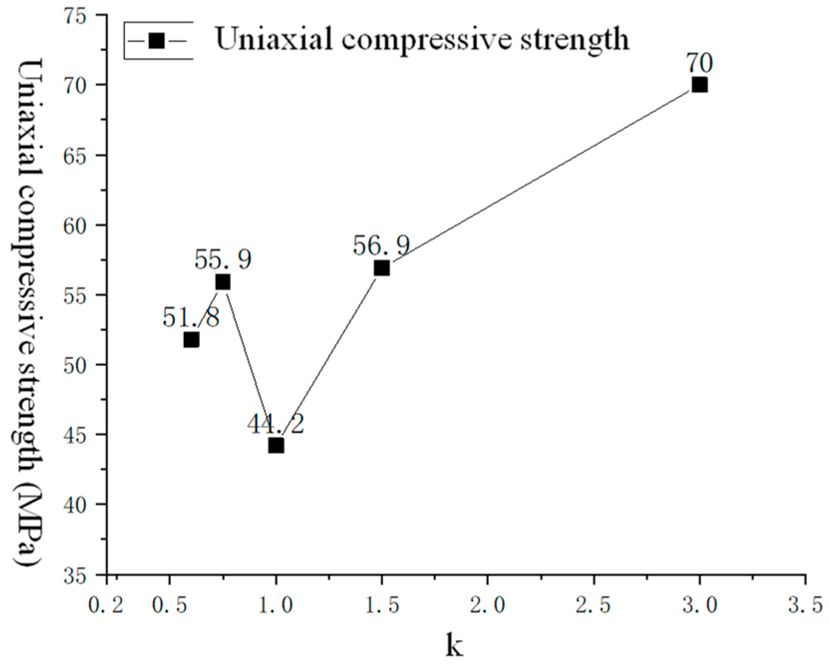
3.2. Strength Analysis

Due to the difference of the shape and size of the holes and the heterogeneity of the rock itself, the peak stress of the sample was different, but it also had certain regularity. From Table 1 and Figure 4, the specific data and trend of the uniaxial compressive strength of the prefabricated marble samples can be obtained. Due to the difference of processing factors and the physical properties of the rock itself, the uniaxial compressive strength of the sample with the same shape and size of the prefabricated hole was different. The k value in Table 1 and Figure 4 represents the ratio of the horizontal axis a to the vertical axis b of the prefabricated holes in the rock sample, that is, k = a/b. Since the horizontal axis a of our prefabricated hole remained unchanged at 12 mm and the vertical axis b increased from 0 mm to 20 mm, the value of k gradually changed from large to small.
It can be seen from Figure 4 that the uniaxial compressive strength changed with the change of the k. However, the overall analysis showed that k = 1 was the dividing line. When k > 1, as the value of k decreased, the uniaxial compressive strength of the marble sample with prefabricated elliptical holes gradually decreased. It shows that when the horizontal axis a is larger than the vertical axis b, as the vertical axis b increases, the uniaxial compressive strength gradually decreases. When k < 1, as the value of k decreases, the uniaxial compressive strength of marble samples with prefabricated elliptical holes will first increase and then decrease. From an overall point of view, when k = 1, that is, when the horizontal and vertical axes are equal, the uniaxial compressive strength of the marble specimens with prefabricated holes is the lowest.

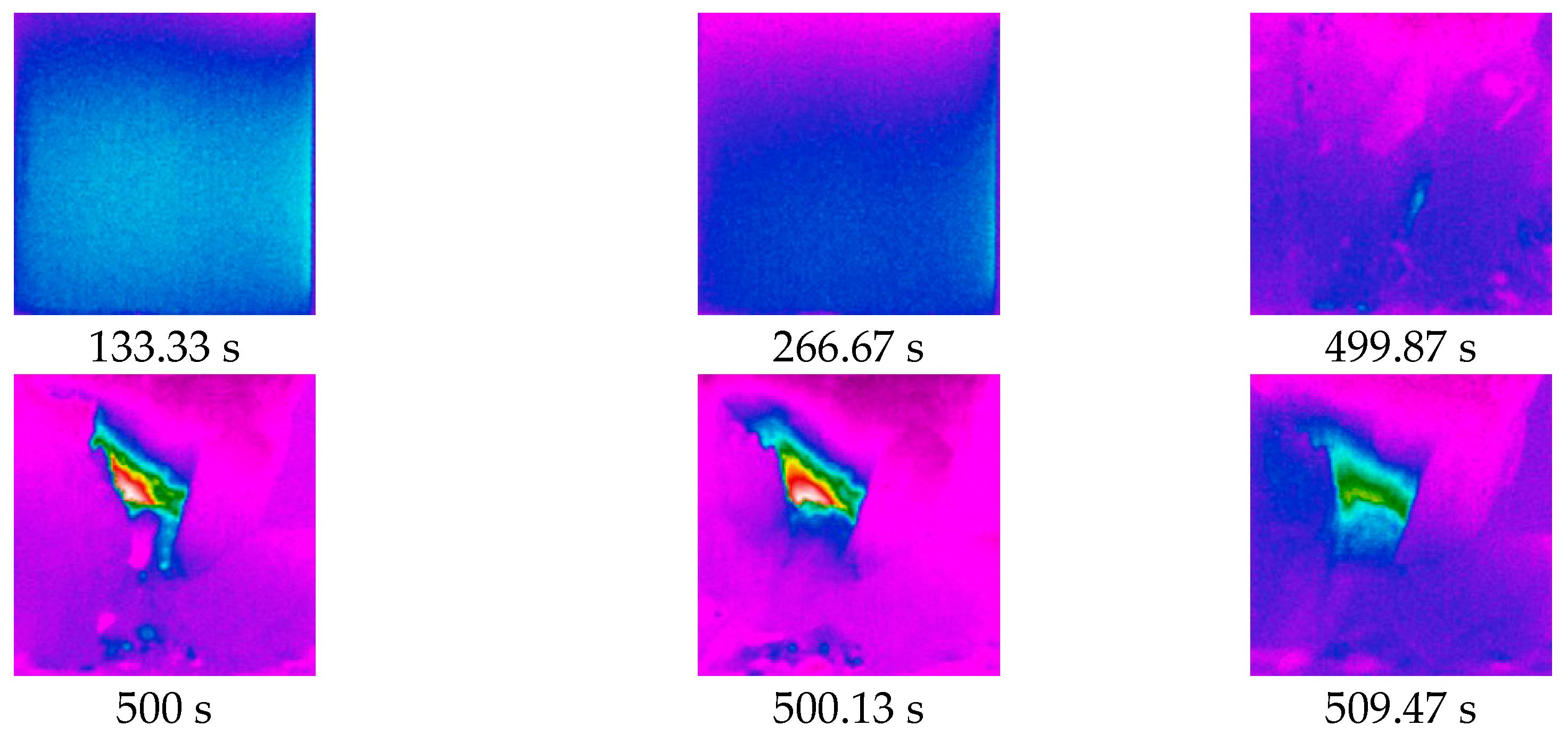
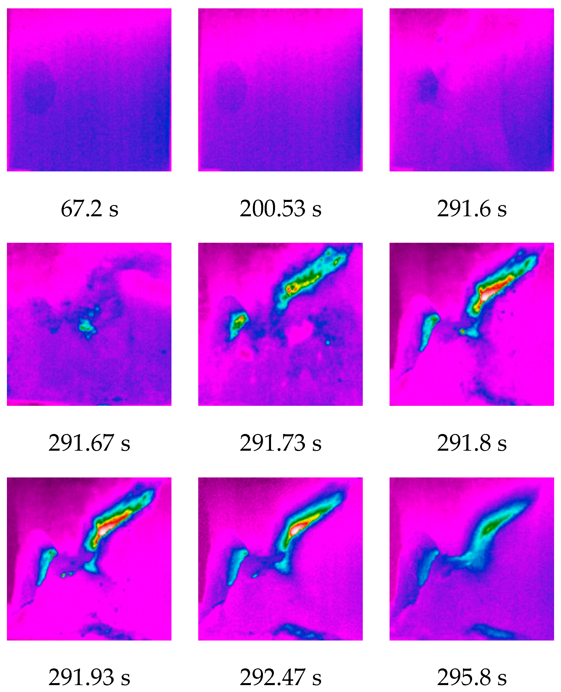
4. Evolution Characteristics of Temperature Field

The FLIR X8501sc thermal imaging camera can record the evolution of the temperature field in the observation area during the uniaxial compression failure process of the sample in high frequency and real time. The calculation and analysis software of the infrared system can also obtain the average temperature, maximum temperature, and minimum temperature change data in the observation area, as well as the temperature distribution data of all pixels in the observation area at any time during the loading process. Figure 5 shows infrared images of the specimen DL1-3 during the destruction process. Because of this study, a total of six groups of 18 uniaxial compression experiments were done. It was not possible to show the infrared image of the destruction process of each specimen. Therefore, the infrared images of two typical specimens of DL1-3 and DL5-3 were selected for comparative analysis to demonstrate the influence of prefabricated holes on the mechanical properties of rocks.

4.1. Analysis of Infrared Results of Typical Specimens

Figure 5 is a cloud diagram of the temperature field evolution of the DL1-3 specimen during uniaxial compression failure. Figure 6 shows the temperature–time change curve of the sample failure process. Figure 7 shows the temperature oscillogram of the observation area at the critical moment during the destruction of the sample.
From Figure 5, we can see the evolution of the temperature field in the observation area during the uniaxial compression test of the DL1-3 sample. From the temperature field cloud diagram from 133.3 to 266.67 s, the color temperature distribution of the temperature field cloud diagram changed little. From the temperature field cloud diagram from 499.87 s to 509.47 s, the sample was brittle failure under continuous loading pressure. The dense particles inside the sample generated a lot of heat energy under the action of intense friction, forming an obvious local heating zone.
Combining with the temperature–time variation curve of the observation area in the uniaxial compression failure process of the sample in Figure 6, it can be seen that the maximum temperature, the minimum temperature, and the average temperature in the observation area changed little during the time period from 0 s to 499.87 s when the sample was loaded. The maximum temperature slowly dropped from 28.66 °C to 28.08 °C. The minimum temperature gradually dropped from 27.68 °C to about 27.01°C. The average temperature gradually dropped from 28.25 °C to about 27.62 °C. After 499.87 s, due to the propagation and penetration of internal cracks in the sample, macroscopic failure occurred. The maximum temperature of the observation area increased sharply, the average temperature also increased, and the minimum temperature decreased. It shows that the brittle failure process of DL1-3 sample will form a local heating zone and a local cooling zone. The range and extent of the temperature increase in the heating zone were greater than those in the cooling zone, so the overall performance was temperature rises. In the brittle failure stage of the sample, the minimum temperature decreased from 27.04 °C to 26.83 °C, a decrease of about 0.2 °C. The maximum temperature rose sharply from 28.17 °C in 499.87 s to 35.87 °C in 500 s, an increase of to 7.7 °C. The average temperature rose from 27.56 °C to 27.75 °C, an increase of about 0.19 °C. The minimum and average temperature changes were relatively small, and the maximum temperature changes were relatively large.
Figure 7 shows the temperature distribution oscillogram of the observation area at any time during the sample loading process, where each red dot represents a pixel. The oscillogram at the early stage of loading is shown in 133.3 s. The temperature distribution was relatively uniform. A large number of distributions were between about 27.4 °C~28.2 °C and a few were between 28.2 °C~28.4 °C and 27.2 °C~27.4 °C. It can be seen from the oscillogram of 449.87 s that the trend of local aggregation in the high-temperature region began to appear. At 500 s, it can be seen that the temperature distribution of some pixels was 28.2 °C~35.9 °C, forming a local heating zone. It can be seen from the oscillogram of 509.47°C that the maximum temperature in the local heating zone dropped from 35.9 °C to 29.2 °C. The temperature in the local heating zone first rose rapidly and then dropped relatively slowly.
Figure 8 below is a cloud diagram of temperature field changes during uniaxial compression failure of DL5-3 sample. Figure 9 shows the temperature–time change curve of the sample failure process. Figure 10 shows the temperature oscillogram of the observation area at the critical moment during the destruction of the sample.
From Figure 8, we can see the evolution of the temperature field in the observation area during the uniaxial compression test of the DL5-3 sample. In the time period of 0~291.67 s, the color temperature distribution of the temperature cloud image in the observation area of the sample was uniform and the amount of change was small. At 291.67 s, the temperature-changing area gradually appeared. The temperature-changing area gradually increased with the destruction of the sample and finally formed a semi-”X” deformation temperature area.
It can be seen from Figure 9 that the maximum temperature, minimum temperature, and average temperature in the observation area of the sample had very small changes during the period of 0 to 291.67 s, and the overall trend was horizontal. The maximum temperature gradually dropped from 26.61 °C to 26.51 °C. The minimum temperature dropped from 25.83 °C to 25.71 °C. The average temperature slowly dropped from 26.23 to 26.13 °C. At the moment of 291.67 s, the maximum temperature, the minimum temperature, and the average temperature all changed abruptly, which proved that brittle failure began to appear at 291.67 s. The minimum temperature decreased from 25.72 °C to 25.62 °C, a decrease of 0.1 °C, with a relatively small change. The maximum temperature rose sharply from 26.53 °C to 37.48 °C, with a particularly large change, rising 10.95 °C. The average temperature rose from 26.11 °C to 26.30 °C, an increase of 0.19 °C, and the range of change was relatively small. From the temperature change curve of the observation area during the sample loading process, it can be seen that during the brittle failure stage of the sample, the particles inside the sample released a large amount of heat energy due to intense friction, forming a local heating zone in the observation area. The location of the local heating zone coincided with the crack penetration area, and the crack penetration caused energy release to form a local cooling zone. Therefore, the overall performance of the sample observation area was increased and then gradually decreased to ambient temperature.
It can be seen from Figure 10 that the temperature distribution of all pixels in the sample observation area at 67.2 s and 200.53 s was extremely similar and the temperature was evenly distributed between 25.8 °C and 26.5 °C. The sample suffered brittle failure at 291.67 s, and some pixels began to heat up. As can be seen from the 291.8-s temperature pixel curve, the maximum temperature rose sharply by 37.5 °C and then quickly began to fall. The temperature distribution of all pixels in the observation area of the sample changed dramatically in a short time. During the brittle failure stage, the local heating zone showed a trend of sudden temperature rise and drop, and the whole observation zone also showed this trend. The variation range and distribution area of the local cooling zone were relatively small and the overall impact was small.
Figure 7 and Figure 10 are graphs of temperature field changes during the loading process of two different specimens. From the two pictures, it can be seen that the temperature field pictures of the two specimens before failure were similar. However, there was a clear difference in the temperature field between the two in the process of specimen failure. The main reason is that the specimen in Figure 10 had prefabricated holes, while Figure 7 was a complete specimen, which led to different temperature field changes when the two were broken.

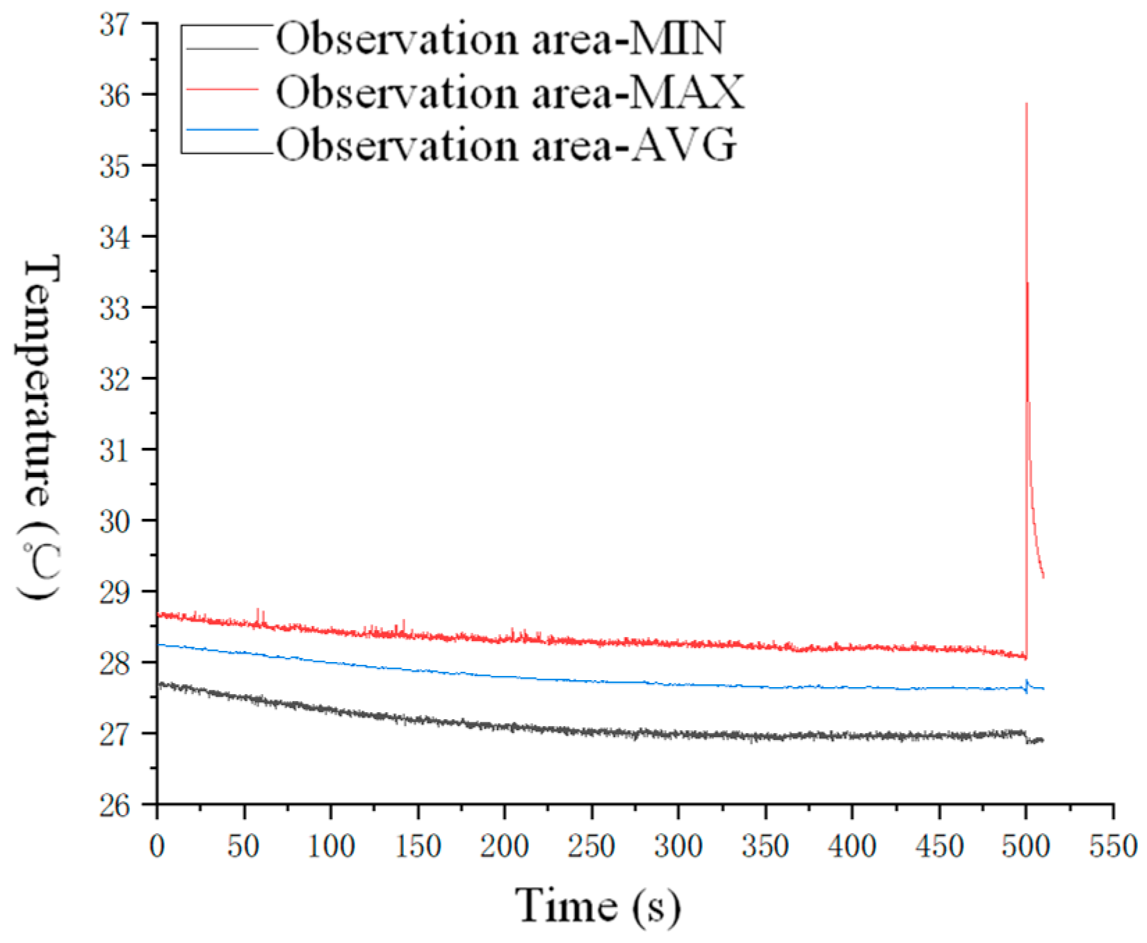
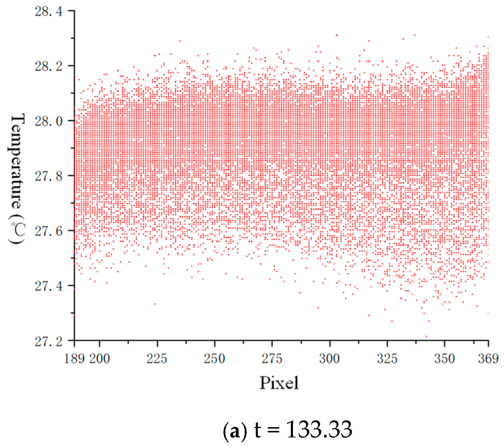
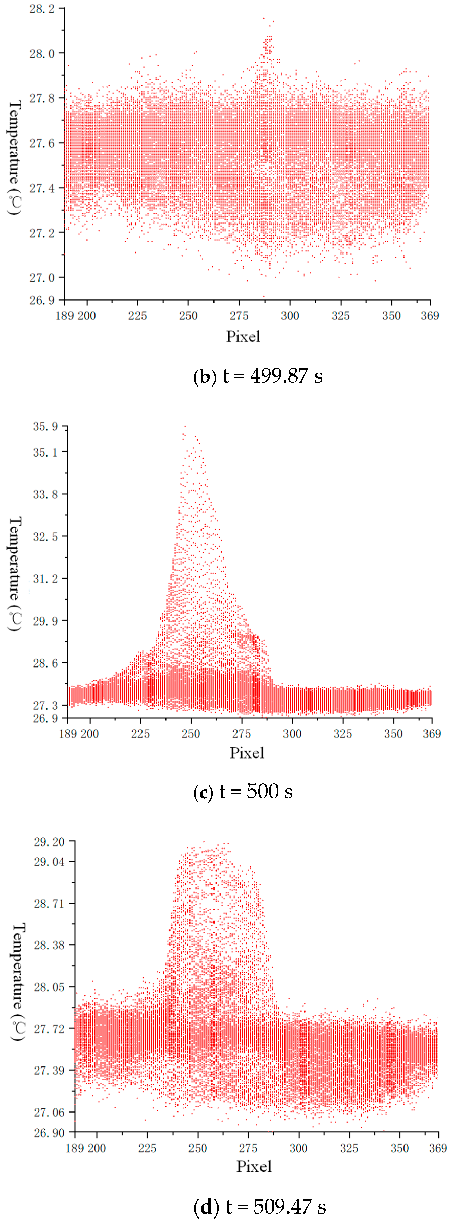
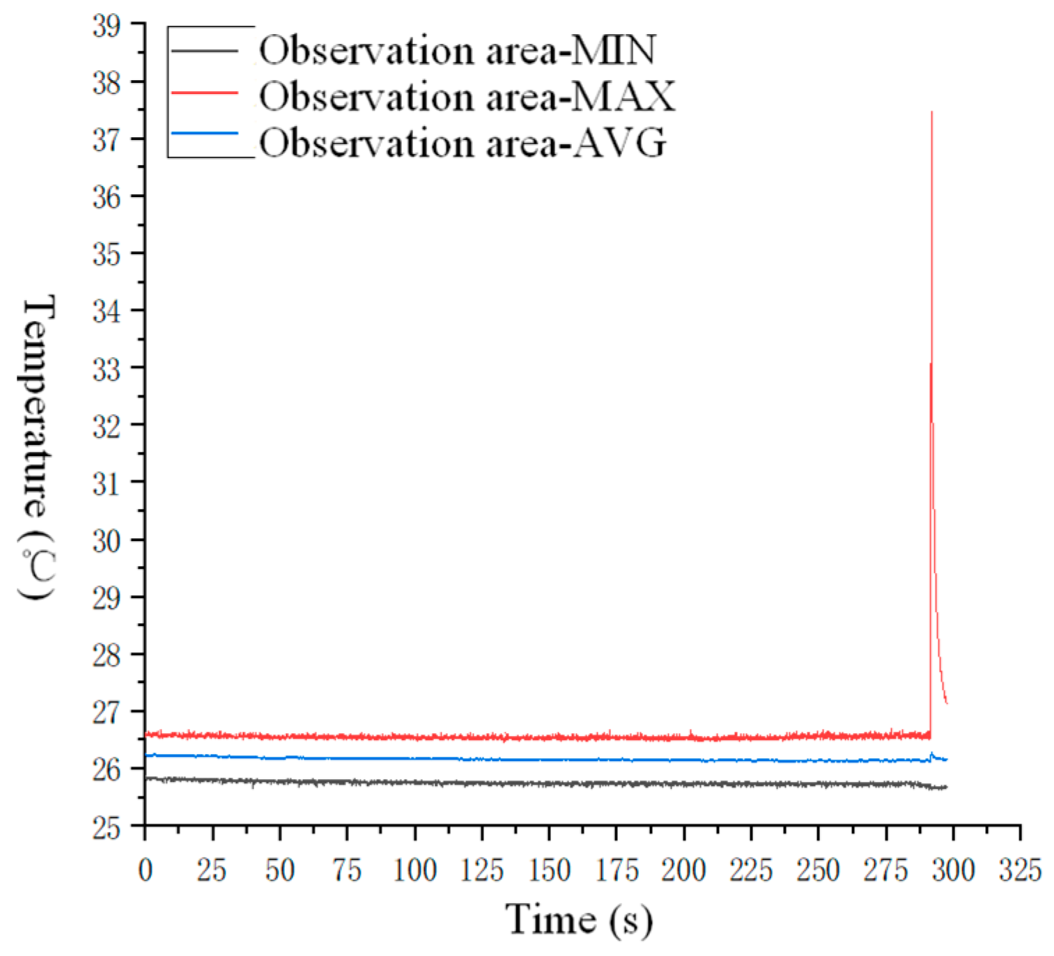
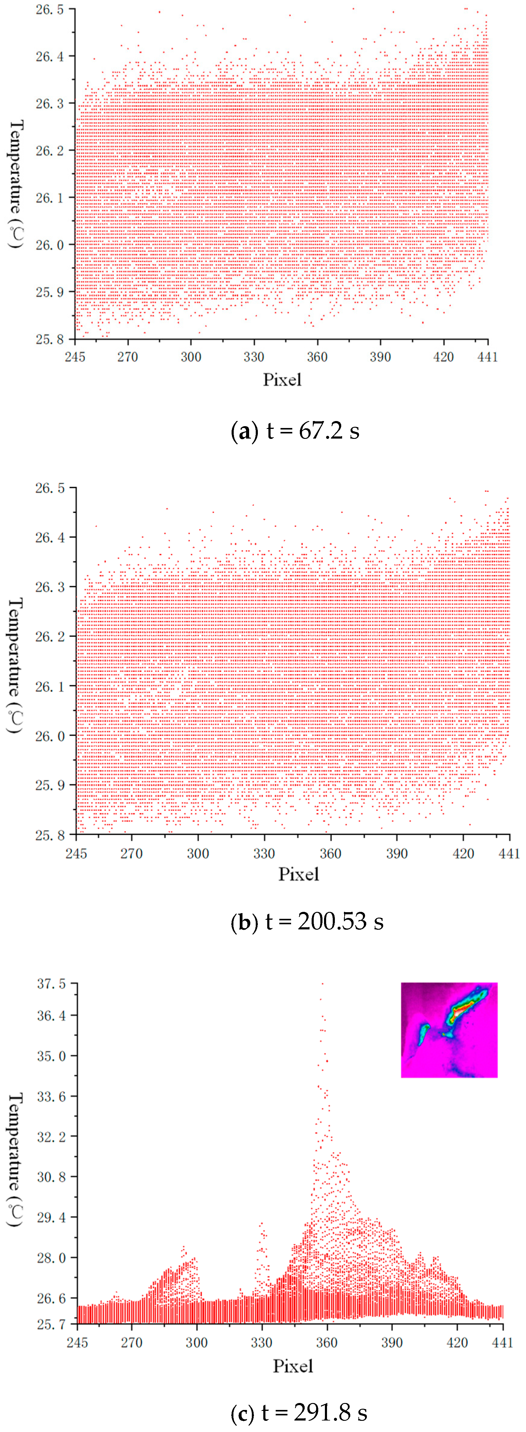
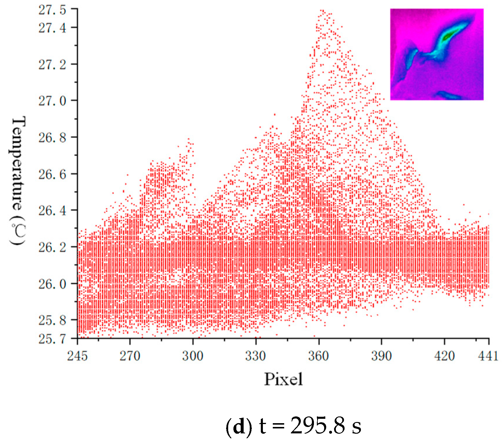
4.2. Temperature Change Trend Analysis

Through the analysis of temperature change data in the observation area during the uniaxial compression failure process of the prefabricated marble sample obtained by the infrared thermal imaging camera, we obtained the maximum temperature, minimum temperature, and average temperature change (△tmax, △tmin, △tavg) in the loading stage and brittle failure stage of the sample, as shown in Table 2.
It can be seen from Table 2 that the prefabricated hole marble sample was loaded from the beginning to the brittle failure stage. The maximum temperature, minimum temperature, and average temperature of the observation area of the sample decreased, and the range of decrease was 0.02~1 °C. In the brittle failure stage, the maximum temperature in the observation area of the sample increased sharply, with a large amount of change, and the maximum increase observed reached 10.96 °C. The minimum temperature dropped sharply, and the drop range was about 0.07 °C~0.2 °C. The average temperature increased sharply, rising by about 0.05 °C to 0.19 °C.
From Table 2 we can know the temperature change rate of all rock samples during the loading process, including the minimum temperature, maximum temperature, and average temperature. During the loading stage, all the temperatures of the rock sample showed a downward trend, mainly due to the accumulation of energy in the loading process, which caused the surface temperature of the sample to decrease. In the brittle failure stage, macroscopic cracks appeared on the surface of the specimen, which led to the dissipation of the accumulated energy inside, which increased the maximum temperature and average temperature of the specimen. Among them, the maximum temperature increase of the specimen was relatively large, mainly concentrated at the moment when the specimen ruptured, because the temperature increase at the moment of the specimen rupture was mainly due to the change of the ambient temperature. Therefore, the average temperature of the specimen should be the main research object.
After statistical calculation, the average value of the average temperature change of all specimens during the loading stage was −0.29 °C and the standard deviation was 0.14 °C. The standard deviation reflects the degree of dispersion of the value relative to the average value, indicating that the dispersion of the loading stage is greater. During the brittle failure stage, the average temperature change of all rock samples was 0.12 degrees and the standard deviation was 0.04 °C. It shows that the dispersion of the average temperature change in the destruction stage was small. The comparison between the standard deviation and the average value shows that the temperature change rate in the loading stage was unstable, while the temperature change rate in the failure stage was relatively small, which is statistically significant.

5. Conclusions

Aiming at the scientific problem of detecting the mechanical behavior of rock masses in the engineering environment, the marble with different prefabricated holes was used as the research object and uniaxial compression experiments and infrared detection research were carried out. Through the processing and analysis of the infrared image, the average infrared temperature change revealed the changing law of the rock mass under the action of external load, and the infrared image represented the structural response of the rock mass and the degree of damage of the rock mass. This research is of great significance to the understanding of the mechanical behavior and failure mechanism of complex rock mass structures. Infrared thermal imaging technology has broad application prospects.
(1) Prefabricated holes will affect the strength of the marble. When k > 1, with the decrease of k, the uniaxial compressive strength of the sample gradually decreases. It shows that as the vertical axis b increases, the uniaxial compressive strength gradually decreases. When k < 1, as the k decreases, the uniaxial compressive strength of the sample will first increase and then decrease. When k = 1, the uniaxial compressive strength of the marble specimens with prefabricated holes is the lowest. It shows that ratio of horizontal and vertical axis k has a very obvious effect on the uniaxial compressive strength and the strength of marble is the lowest in the case of circular holes.
(2) During the loading stage, the color temperature distribution of the temperature field cloud map changed little. In the brittle failure stage, obvious local temperature change areas were formed. The randomly distributed infrared temperature represented the elastic deformation of the rock mass, and the large-scale concentrated infrared temperature represented the plastic deformation of the rock mass. The temperature distribution of infrared images revealed that, under the action of external load, there was energy accumulation inside the rock, which eventually led to brittle failure of the rock.
(3) During the loading stage, the maximum temperature, minimum temperature, and average temperature of the observation area showed a downward trend. It was mainly due to the accumulation of energy in the loading process of the rock sample that caused the surface temperature of the specimen to decrease. In the brittle failure stage, macroscopic cracks appeared on the surface of the specimen, which led to the dissipation of the accumulated energy inside, which increased the maximum temperature and average temperature of the specimen. Since the temperature increase at the moment of specimen rupture was mainly the change of ambient temperature, the average temperature of the specimen should be the main research object.
In this paper, the whole process of the uniaxial compression test of marble with prefabricated holes was observed in real time through the synchronous, high-frequency infrared thermal imaging camera. The experimental results obtained the evolution characteristics of the infrared heat radiation temperature field in the observation area during the sample loading process and the infrared heat radiation temperature information at any point in the observation area at any time. However, due to the experimental conditions, only one surface could be observed by one infrared thermal imaging camera. If multiple infrared thermal imaging cameras can be used for simultaneous and omni-directional observation, it will be of more research significance.

Author Contributions

Conceptualization, C.Z.; methodology, M.H.; software, Q.L.; validation, H.Z., P.G. and Y.P.; data curation, Q.L.; writing—original draft preparation, Q.L.; writing—review and editing, Y.P.; funding acquisition, Y.P. and C.Z. All authors have read and agreed to the published version of the manuscript.

Funding

This research was funded by the funding of National Natural Science Foundation of China, grant number 41702381; Zhejiang Public Welfare Technology Research Program/Social Development, grant number LGF20D020002; Key Laboratory of Rock Mechanics and Geohazards of Zhejiang Province, grant number ZJRMG-2020-02 and Fundamental Research Funds for the Central Universities, grant number B210201001.

Data Availability Statement

The data are available and explained in this article; readers can access the data supporting the conclusions of this study.

Conflicts of Interest

Authors declare no conflict of interest. The manuscript is approved by all authors for publication. I would like to declare on behalf of my coauthors that the work described is original and has not been previously published.

References

  1. Huon, V.; Cousin, B.; Wattrisse, B.; Maisonneuve, O. Investigating the thermo-mechanical behaviour of cementitious materials using image processing techniques. Cem. Concr. Res. 2009, 39, 529–536. [Google Scholar] [CrossRef]
  2. Ma, S.-P.; Wang, L.-G.; Zhao, Y.-H. Experimental study on deformation field evolution during failure procedure of a rock borehole structure. Yantu Lixue (Rock Soil Mech.) 2006, 27, 1082–1086. [Google Scholar]
  3. Yong, R.; Ye, J.; Li, B.; Du, S. Determining the maximum sampling interval in rock joint roughness measurements using Fourier series. Int. J. Rock Mech. Min. Sci. 2018, 101, 78–88. [Google Scholar] [CrossRef]
  4. He, M.; Miao, J.; Feng, J. Rock burst process of limestone and its acoustic emission characteristics under true-triaxial unloading conditions. Int. J. Rock Mech. Min. Sci. 2010, 47, 286–298. [Google Scholar] [CrossRef]
  5. Li, A.; Zhang, R.; Ai, T.; Gao, M.; Zhang, Z.; Jing, X. Acoustic emission space-time evolution rules and failure precursors of granite under uniaxial compression. Chin. J. Geotech. Eng. 2016, 38, 306–311. [Google Scholar]
  6. Yang, S.-Q.; Tian, W.-L.; Huang, Y.-H.; Ma, Z.-G.; Fan, L.-F.; Wu, Z.-J. Experimental and discrete element modeling on cracking behavior of sandstone containing a single oval flaw under uniaxial compression. Eng. Fract. Mech. 2018, 194, 154–174. [Google Scholar] [CrossRef]
  7. Li, S.; Li, T.; Wang, G.; Bai, S. CT real-time scanning tests on rock specimens with artificial initial crack under uniaxial conditions. Yanshilixue Yu Gongcheng Xuebao/Chin. J. Rock Mech. Eng. 2007, 26, 484–492. [Google Scholar]
  8. Sun, X.; Li, X.; Zheng, B.; He, J.; Mao, T. Study on the progressive fracturing in soil and rock mixture under uniaxial compression conditions by CT scanning. Eng. Geol. 2020, 279, 105884. [Google Scholar] [CrossRef]
  9. Wang, Y.; Xiao, Y.; Hou, Z.; Li, C.; Wei, X. In situ X-ray computed tomography (CT) investigation of crack damage evolution for cemented paste backfill with marble waste block admixture under uniaxial deformation. Arab. J. Geosci. 2020, 13, 1–16. [Google Scholar] [CrossRef]
  10. Brand, B.T.; Roswell, G.A. Laboratory investigation of the electrodynamics of rock fracture. Nature 1986, 321, 488–492. [Google Scholar]
  11. Luong, M. Infrared thermographic scanning of fatigue in metals. Nucl. Eng. Des. 1995, 158, 363–376. [Google Scholar] [CrossRef] [Green Version]
  12. Luong, M.P. Infrared Thermography of Macrostructural Aspects of Thermoplasticity. Micro-and Macrostructural Aspects of Thermoplasticity; Springer: Dordrecht, The Netherlands, 2006; pp. 437–446. [Google Scholar]
  13. Luong, M.P.; Parganin, D.; Loizeau, J. Infrared Thermography of Thermomechanical Couplings in Solids. In Iutam Symposium on Advanced Optical Methods and Applications in Solid Mechanics; Springer: Berlin/Heidelberg, Germany, 2000; Volume 82, pp. 297–304. [Google Scholar]
  14. Shanjun, L.; Lixin, W.; Huanping, W.; Yuhua, W.; Tao, C.; Guohua, L. Quantitative study on the thermal infrared radiation of dark mineral rock in condition of uniaxial loading. Chin. J. Rock Mech. Eng. 2002, 21, 1585–1589. [Google Scholar]
  15. Shan-jun, L.; Li-xin, W.; Chuan-ying, W.; Daqing, G.; Yuhua, W. Remote sensing-rock mechanics (VIII): TIR omens of rock fracturing. Chin. J. Rock Mech. Eng. 2004, 23, 1621–1627. [Google Scholar]
  16. Shanjun, L.; Lixin, W.; Yuhua, W.; Yongqiang, L. Remote sensing-rock mechanics (V)—Analysis on the factors affecting thermal infrared radiation in process of rock viscosity sliding. Chin. J. Rock Mech. Eng. 2004, 23, 730–735. [Google Scholar]
  17. Liu, S.-J.; Wu, L.-X.; Zhang, Y.-B. Temporal-spatial evolution features of infrared thermal images before rock failure. J. Northeast. Univ. Nat. Sci 2009, 30, 1034–1038. [Google Scholar]
  18. Wu, L.; Liu, S.; Wu, Y.; Li, Y. Remote sensing-rock mechanics (II)—Laws of thermalinfrared radiation from viscosity-sliding of bi-shearedfaults and its meanings for tectonic earthquake omens. Chin. J. Rock Mech. Eng. 2004, 23, 192–198. [Google Scholar]
  19. Lixin, W.; Shanjun, L.; Yunhua, W. Remote-sensing-rock mechanics (IV)—Laws of thermal infrared radiation from compressively-sheared fracturing of rock and its meanings for earthquake omens. Chin. J. Rock Mech. Eng. 2004, 23, 539–544. [Google Scholar]
  20. Gong, W.; Peng, Y.; Sun, X.; He, M.; Zhao, S.; Chen, H.; Xie, T. Enhancement of low-contrast thermograms for detecting the stressed tunnel in horizontally stratified rocks. Int. J. Rock Mech. Min. Sci. 2015, 74, 69–80. [Google Scholar] [CrossRef]
  21. Gong, W.; Peng, Y.; He, M.; Wang, J. Thermal image and spectral characterization of roadway failure process in geologically 45° inclined rocks. Tunn. Undergr. Space Technol. 2015, 49, 156–173. [Google Scholar] [CrossRef]
  22. Gong, W.; Peng, Y.; He, M.; Xie, T.; Zhao, S. An overview of the thermography-based experimental studies on roadway excavation in stratified rock masses at CUMTB. Int. J. Min. Sci. Technol. 2015, 25, 333–345. [Google Scholar] [CrossRef]
  23. Zhang, Y.-b.; Liu, S. Thermal radiation temperature field variation of hole rock in loading process. Rock Soil Mech. 2011, 32, 1013–1017. [Google Scholar]
  24. Zhang, Y.; Wu, W.; Yao, X.; Liang, P.; Tian, B.; Huang, Y.; Liang, J. Acoustic emission-infrared characteristics and damage evolution of granite under uniaxial compression. Rock Soil Mech 2020, 41, 139–146. [Google Scholar]
  25. Wu, X.; Gao, X.; Liu, X.; Zhao, K. Abnormality of infrared temperature mutation in the process of saturated siltstone failure. J. China Coal Soc. 2015, 40, 328–336. [Google Scholar]
  26. Wu, X.; Gao, X.; Zhao, K.; Liu, J.; Liu, X. Abnormality of transient infrared temperature field (ITF) in the process of rock failure. Chin. J. Rock Mech. Eng. 2016, 35, 1578–1594. [Google Scholar]
  27. Ma, L.; Zhang, Y.; Sun, H.; Wang, S.; Najeem, A. Experimental study on dependence of infrared radiation on stress for coal fracturing process. J. China Coal Soc. 2017, 42, 140–147. [Google Scholar]
  28. Ma, L.; Zhang, D.; Guo, X.; Sun, H.; Najeem, A.; Zhang, Y. Characteristics on the variance of differential infrared image sequence during coal failures under uniaxial loading. Chin. J. Rock Mech. Eng. 2017, 36, 3927–3934. [Google Scholar]
  29. Zhou, Z.; Chang, Y.; Cai, X. Experimental study of infrared radiation effects of rock with different loading rates. J. Cent. South Univ. (Sci. Technol.) 2019, 50, 1127–1134. [Google Scholar]
  30. Ma, J.; Niu, X.; Liu, X.; Wang, Y.; Wen, T.; Zhang, J. Thermal Infrared Imagery Integrated with Terrestrial Laser Scanning and Particle Tracking Velocimetry for Characterization of Landslide Model Failure. Sensors 2019, 20, 219. [Google Scholar] [CrossRef] [Green Version]
  31. Teena, M.; Manickavasagan, A. Thermal Infrared Imaging. In Imaging with Electromagnetic Spectrum; Manickavasagan, A., Jayasuriya, H., Eds.; Springer: Berlin/Heidelberg, Germany, 2014; pp. 147–173. [Google Scholar]
  32. Mujtaba, B.; De Lima, J.L.M.P. Laboratory testing of a new thermal tracer for infrared-based PTV technique for shallow overland flows. Catena 2018, 169, 69–79. [Google Scholar] [CrossRef]
  33. Morello, R. Potentialities and limitations of thermography to assess landslide risk. Measurement 2018, 116, 658–668. [Google Scholar] [CrossRef]
  34. Sobrino, J.A.; Del Frate, F.; Drusch, M.; Jimenez, J.C.; Manunta, P.; Regan, A. Review of Thermal Infrared Applications and Requirements for Future High-Resolution Sensors. IEEE Trans. Geosci. Remote. Sens. 2016, 54, 2963–2972. [Google Scholar] [CrossRef]
  35. Frodella, W.; Gigli, G.; Morelli, S.; Lombardi, L.; Casagli, N. Landslide Mapping and Characterization through Infrared Thermography (IRT): Suggestions for a Methodological Approach from Some Case Studies. Remote Sens. 2017, 9, 1281. [Google Scholar] [CrossRef] [Green Version]
  36. Xu, B.; Dong, S.; Yin, S.; Li, S.; Xu, Y.; Dai, Z. Analysis of Crack Initiation and Propagation Thresholds of Inclined Cracks under High-Pressure Grouting in Ordovician Limestone. Energies 2021, 14, 360. [Google Scholar] [CrossRef]
  37. Wang, Y.; Tang, J.; Dai, Z.; Yi, T. Experimental study on mechanical properties and failure modes of low-strength rock samples containing different fissures under uniaxial compression. Eng. Fract. Mech. 2018, 197, 1–20. [Google Scholar] [CrossRef]
  38. Yang, S.; Huang, Y.; Jing, H.; Liu, X. Discrete element modeling on fracture coalescence behavior of red sandstone containing two unparallel fissures under uniaxial compression. Eng. Geol. 2014, 178, 28–48. [Google Scholar] [CrossRef]
  39. Shi, G.; Yang, X.; Yu, H.; Zhu, C. Acoustic emission characteristics of creep fracture evolution in double-fracture fine sandstone under uniaxial compression. Eng. Fract. Mech. 2019, 210, 13–28. [Google Scholar] [CrossRef]
  40. Li, Z.; Liu, S.; Ren, W.; Fang, J.; Zhu, Q.; Dun, Z. Multiscale Laboratory Study and Numerical Analysis of Water-Weakening Effect on Shale. Adv. Mater. Sci. Eng. 2020, 2020, 1–14. [Google Scholar] [CrossRef]
  41. Meng, Q.; Wang, H.; Cai, M.; Xu, W.; Zhuang, X.; Rabczuk, T. Three-dimensional mesoscale computational modeling of soil-rock mixtures with concave particles. Eng. Geol. 2020, 277, 105802. [Google Scholar] [CrossRef]
  42. Wang, Y.; Zhang, B.; Gao, S.; Li, C. Investigation on the effect of freeze-thaw on fracture mode classification in marble subjected to multi-level cyclic loads. Theor. Appl. Fract. Mech. 2021, 111, 102847. [Google Scholar] [CrossRef]
  43. Li, Z.; Liu, H.; Dun, Z.; Ren, L.; Fang, J. Grouting effect on rock fracture using shear and seepage assessment. Constr. Build. Mater. 2020, 242, 118131. [Google Scholar] [CrossRef]
  44. Meng, Q.-X.; Wang, H.; Xu, W.-Y.; Chen, Y.-L. Numerical homogenization study on the effects of columnar jointed structure on the mechanical properties of rock mass. Int. J. Rock Mech. Min. Sci. 2019, 124, 104127. [Google Scholar] [CrossRef]
Figure 1. Marble rock samples.
Energies 14 00713 g001
Figure 2. Test system for deep rock gas escape under Temperature-Pressure coupling condition.
Energies 14 00713 g002
Figure 3. Stress–strain curves of marble specimens.
Energies 14 00713 g003
Figure 4. Trend chart of uniaxial compressive strength changing with k.
Energies 14 00713 g004
Figure 5. Cloud diagram of temperature field change during DL1-3 specimen failure.
Energies 14 00713 g005
Figure 6. Temperature—time change curve of DL1-3 sample destruction process.
Energies 14 00713 g006
Figure 7. The oscillogram of the temperature in the observation area at the critical moment of the DL1-3 sample destruction.
Energies 14 00713 g007aEnergies 14 00713 g007b
Figure 8. Cloud diagram of temperature field change during DL5-3 specimen failure.
Energies 14 00713 g008
Figure 9. Temperature—time change curve of DL5-3 sample destruction process.
Energies 14 00713 g009
Figure 10. The oscillogram of the temperature in the observation area at the critical moment of the DL5-3 sample destruction.
Energies 14 00713 g010aEnergies 14 00713 g010b
Table 1. Uniaxial compressive strength of all samples.
NumberPictureSchematic Diagramk (a/b)Uniaxial Compressive Strength (MPa)Difference Value (MPa)Average UCS (MPa)
DL1-1 Energies 14 00713 i001 Energies 14 00713 i002116.53.2113.3
DL1-2105.8−7.5
DL1-3117.54.2
DL2-1 Energies 14 00713 i003 Energies 14 00713 i004378.98.970.0
DL2-263.7−6.3
DL2-367.5−2.5
DL3-1 Energies 14 00713 i005 Energies 14 00713 i0061.561.84.956.9
DL3-251.7−5.2
DL3-357.40.5
DL4-1 Energies 14 00713 i007 Energies 14 00713 i008140−4.244.2
DL4-248.94.7
DL4-343.7−0.5
DL5-1 Energies 14 00713 i009 Energies 14 00713 i0100.7553.2−2.755.9
DL5-252.9−3
DL5-361.75.8
DL6-1 Energies 14 00713 i011 Energies 14 00713 i0120.657.8651.8
DL6-250.6−1.2
DL6-347.1−4.7
Table 2. Temperature variation of all rock samples during the failure process.
NumberPictureLoading StageBrittle Failure Stage
△tmin (°C)△tmax (°C)△tavg (°C) ¯ tavg (°C) △tmin (°C)△tmax (°C)△tavg (°C) ¯ tavg (°C)
DL1-1 Energies 14 00713 i013−0.36−0.39−0.37−0.29−0.156.510.160.12
DL1-2−0.23−0.43−0.29−0.135.820.17
DL1-3−0.67−0.58−0.63−0.27.700.19
DL2-1 Energies 14 00713 i014−0.24−0.22−0.23−0.112.440.14
DL2-2−0.27−0.16−0.25−0.093.350.12
DL2-3−0.31−0.27−0.29−0.154.760.11
DL3-1 Energies 14 00713 i015−0.49−0.42−0.47−0.125.230.13
DL3-2−0.34−0.32−0.33−0.071.640.07
DL3-3−0.11−0.11−0.11−0.081.680.05
DL3-1 Energies 14 00713 i016−0.47−0.43−0.46−0.112.310.08
DL3-2−0.39−0.33−0.37−0.145.760.14
DL3-3−0.33−0.29−0.32−0.096.330.15
DL5-1 Energies 14 00713 i017−0.18−0.17−0.17−0.133.210.09
DL5-2−0.23−0.21−0.22−0.084.570.10
DL5-3−0.12−0.10−0.10−0.110.960.19
DL6-1 Energies 14 00713 i018−0.23−0.17−0.21−0.142.340.09
DL6-2−0.09−0.07−0.08−0.091.570.08
DL6-3−0.35−0.30−0.33−0.072.110.06
Publisher’s Note: MDPI stays neutral with regard to jurisdictional claims in published maps and institutional affiliations.

