Article

Strengthening Mechanism of Studs for Embedded-Ring Foundation of Wind Turbine Tower

1
Department of Structural Engineering, Tongji University, Shanghai 200092, China
2
Shanghai Fengchang Civil Engineering Technology Co., Ltd., Shanghai 200092, China
*
Author to whom correspondence should be addressed.
Energies 2021, 14(3), 710; https://doi.org/10.3390/en14030710
Submission received: 6 December 2020 / Revised: 26 January 2021 / Accepted: 27 January 2021 / Published: 30 January 2021
(This article belongs to the Special Issue Foundation Systems for Offshore Wind Turbines)

Abstract

:
The embedded-ring wind turbine foundations were widely applied in the early development stage of wind power industries because of its properties such as easy installation and adjustment. However, different damages occurred on some embedded-ring wind turbine foundations in recent years. Based on the common damage phenomena of embedded-ring wind turbine foundations, the structural defects and damage mechanisms of embedded-ring wind turbine foundations are analyzed in a gradual way. Cheese head studs are proposed to be welded on the lateral wall of the steel ring to strengthen the connection between the steel ring and the foundation concrete. The foundation pier is elevated 1 m to increase the embedded depth of the steel ring. The circumferential confining pressure is applied on the lateral side of the foundation pier to lead it into a state of pressure. One simplified method is proposed to calculate the contribution of welding studs in this strengthening method. Taking an embedded-ring wind turbine foundation as an example, the numerical analyses for the original foundation and the reinforced one are carried out to compare the stress and strain distribution changes. Based on the numerical results corresponding to the peak and valley value loads, the fatigue life of the concrete and studs are evaluated according to the relevant design codes. The numerical results show that this strengthening method can coordinate the deformation of the embedded steel ring and the foundation concrete by circumferential prestressing and welding studs. The maximum principal stresses of the foundation pier and the fatigue stress range of the concrete around the bottom of the steel ring have been greatly reduced after strengthening. The gaps between the embedded steel ring and the foundation pier are also obviously decreased because of these strengthening measures. The stress concentration phenomena of the concrete around the T-shaped flange have been remarkably improved. The fatigue life can meet the requirements of relevant design codes after strengthening. Therefore, it can be concluded that the safety performance and service life of the embedded-ring foundation can be guaranteed.

1. Introduction

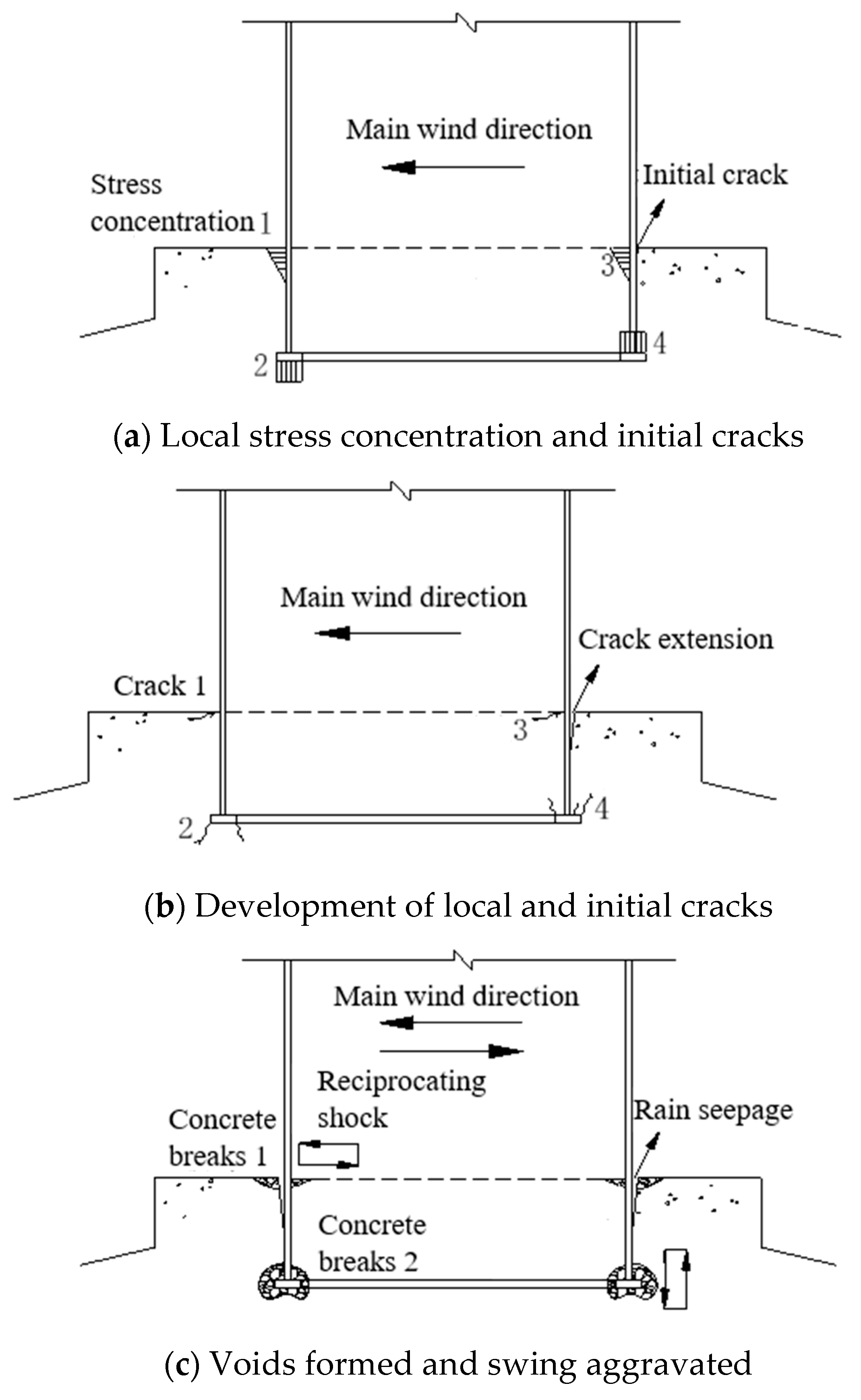
In recent years, in order to solve the shortage of fossil energy and the environmental pollution problems, wind energy has been developed rapidly in the world due to its renewable and pollution-free characteristics. The global cumulative installed wind capacity has already summed up to 650 GW by the end of 2019. In the early development stage of wind power industries, the embedded steel ring is widely applied to connect the upper steel tower with the bottom concrete foundation for the wind turbine system because of its properties such as easy installation and adjustment. At that moment, the unit capacity of wind turbine is relatively small, and hence the bottom forces transferred from the steel tower to the concrete foundation pier are also relatively small. Therefore, although there is not enough constraint stiffness of the steel ring in the concrete foundation due to its shallow embedded depth, this kind of connection type could ensure the reliability of the foundation. However, with the increasing of the wind turbine capacity and the tower height, the bottom forces transferred from the tower to the foundation pier are getting larger and larger. Different damage types occurred on many wind turbine foundations with embedded steel rings (as shown in Figure 1), such as concrete cracking of the foundation surface and concrete crushing around the steel ring [1]. According to the results of the field survey, the damage phenomena of embedded-ring foundations are very common when the wind turbine capacity is greater than 2 MW and the tower height is greater than 80 m. In fact, the damage phenomena of embedded-ring foundations have been concerned by some researchers in recent years. Rapport [2] summarized the damage forms of embedded-ring wind turbine foundations and analyzed the damage causes such as structural defects, unreasonable structural design, dynamic loading, and poor-quality concrete. Currie et al. [3] analyzed the failure mechanisms of embedded-ring foundation and proposed several inexpensive sensors to continuously monitor real-time displacements in embedded-ring wind turbine foundations. Kang et al. [4] developed the finite element model of embedded-ring wind turbine foundation and analyzed the influence of the gap between the steel ring and the concrete foundation on its local damages. Currie et al. [5] presented a wireless monitoring technique by measuring the displacement patterns of the embedded ring of wind turbine to alert its significant movements. Bai et al. [6] investigated the fatigue behavior of concrete in the anchorage area of the foundation under the equivalent fatigue loads. Liu and Yang [7] carried out numerical analyses and found that the height of embedded ring and the arrangement of steel bars around the embedded ring have an influence on the stress distribution of foundation concrete. Lyu et al. [8] investigated the fatigue damage mechanism of embedded-ring wind turbine foundation and results showed that the shear strength of steel bars passing through the steel ring could not meet the shear requirement between the steel ring and the foundation concrete.
In this paper, damage mechanisms of embedded-ring wind turbine foundations are analyzed and strengthening measures are evaluated by numerical analyses. The paper is organized as follows: Section 2 analyzes structural defects of embedded-ring wind turbine foundation. 
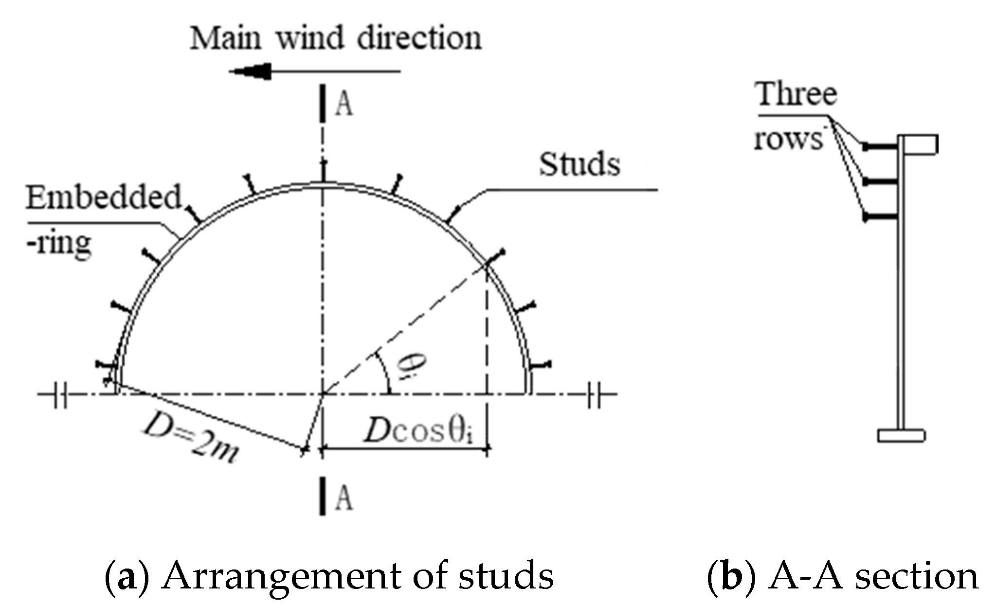
Section 3 proposes a strengthening method to improve the mechanical performance of embedded-ring foundation, which includes adding welded studs, circumferential prestressing, and increasing the embedded depth of the steel ring. 
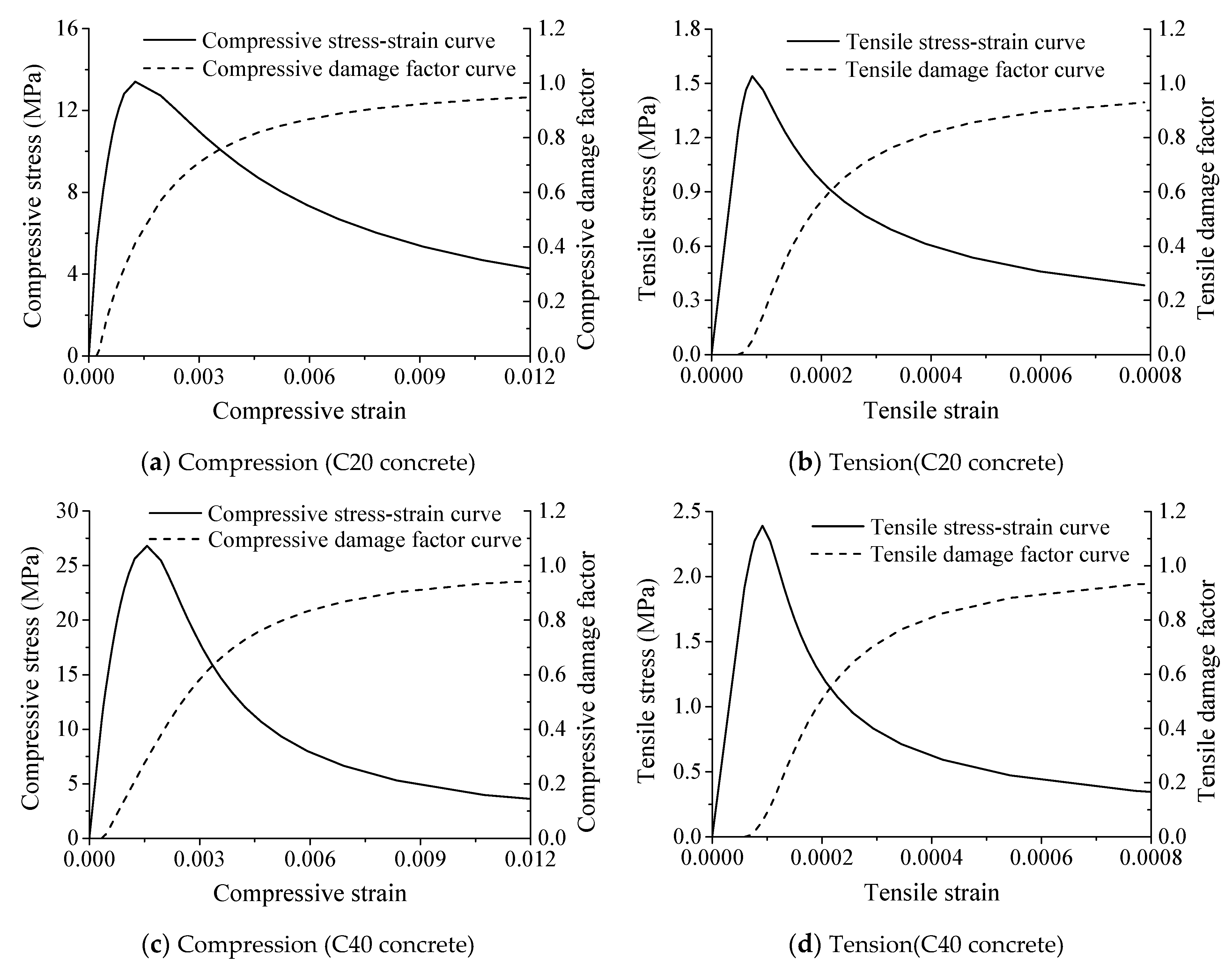
Section 4 describes numerical modeling details of the study case. Section 5 reports the numerical results and evaluates the strengthening method. Finally, some conclusions are discussed in Section 6.

2. Structural Defects of Embedded-Ring Foundation

A typical embedded-ring spread foundation is shown in Figure 2 in which the steel ring is embedded in the foundation concrete. There is a T-shaped flange under the bottom of the embedded-ring to enhance the anchoring effect with the foundation concrete. The L-shaped flange on the top of the steel ring is applied to connect with the upper steel tower by bolts. On the surface, wind turbine embedded-ring foundations are similar in form to embedded-column footings widely used in steel frame structures of civil buildings. However, their mechanical mechanisms are totally different because the relative embedding depths of embedded-ring foundations are much smaller than those of embedded-column footings of frame structures. For tubular embedded-column footings, the embedding depth should be at least three times than its outer diameter according to JGJ99-2015 [9]. Therefore, the foundation concrete could provide enough lateral pressure to transfer the overturning moment that acts on the steel column base [1]. The diameter of the embedded steel ring for a wind turbine with the capacity about or more than one megawatt is generally greater than 4 m, but its embedded depth in the concrete foundation is less than 2 m, which is only about 0.5 times the diameter of the steel ring.
Since the embedded depth of steel ring is too shallow, the restraining stiffness of the foundation pier to the embedded ring is insufficient and the contact pressure from the foundation pier is not enough to resist the overturning bending moment. Therefore, the T-shaped flange plays an important role for the anchoring of steel ring in foundation concrete. The overturning moment of the bottom end of the tower is transferred by both the anchoring effect of the T-shaped flange and the contact pressure from the foundation concrete. Some structural engineers assume directly that the 30%–40% overturning moment is transferred through the contact pressure of the foundation pier and the rest is undertaken by the anchoring effect of T-shaped flange. For embedded-column footings in steel frame structures, welding studs are widely used to enhance the connection between the steel column and the concrete footing. However, for embedded-ring foundations built in the early stage, there are no welding studs on the lateral wall of the steel ring and the only connection with the foundation concrete is the upper and lower steel bars passing through the holes on its lateral wall. However, the concrete of the foundation pier is cut into two parts due to the embedding of the steel ring. The deformations of the embedded steel ring and the concrete foundation are uncoordinated under the overturning moment due to their differences in material properties. There are stress concentration phenomena occurring near the top surface of the foundation pier and around the T-shaped flange under the overturning moment because of the special construction of the steel ring (as shown in Figure 3a). As the increasing of the wind turbine capacity, the stress concentrations become more and more serious and some local cracks possibly appear (as shown in Figure 3b). Under the reciprocating loading, the concretes at these local zones are gradually grinded and gaps will be generated. Over the years, the embedded steel ring might swing slightly in the foundation pier (as shown in Figure 3c). The overturning moment transferred by the contact with the foundation pier decreases gradually and the overturning moment undertaken by the anchoring effect of the T-shaped flange increases gradually. Rainwater or condensate water enters the gaps due to the pumping action and leads to the mortar emitted from the gaps [10]. As the operating time increases, voids will be formed in the foundation concrete near the T-shaped flange. After the rainwater is accumulated in the voids, the damage of the foundation concrete under the reciprocating loading will be exacerbated. The swing of the tower will gradually aggravate and then affect the safety performance of wind turbine system.

3. Strengthening Method

For damaged embedded-ring foundations, the common strengthening method is repairing areas that gap and crack locate by filling cement slurry through the drilled holes on the foundation pier. This method is only a stop-gap measure, not a long-term way to improve the mechanical performance of embedded-ring foundation. The causes of potential damages in embedded-ring foundations still remain and thus gaps and cracks will appear again after a period of time. Some researchers also have proposed some methods to strengthen the damaged embedded-ring foundations. Kang et al. [4] proposed to reinforce the upper surface strength of the foundation and prevent crack generation and propagation by adding annular beam, but analysis results showed that it could not decrease the local stress of concrete near the steel ring. Liu and Yang [7] investigated the role of studs that weld onto the steel ring, and results showed that the steel ring and foundation concrete can work together better with the welded studs. He et al. [11] presented a retrofit strategy in a new embedded-ring wind turbine foundation using an external prestressing technique and found the prestressed loads could reduce the width of cracks inside the steel ring at the bottom. Chen et al. [1] proposed a strengthening method using a circumferential prestressing technique and the numerical results showed that this method can improve the anti-fatigue performance of the concrete around the steel ring effectively.
The common damage phenomena of embedded-ring foundations include obvious gaps between the embedded ring and the foundation, waterproof layers at the interface damaged, and cement slurries emerged on the top surfaces of foundations inside and outside towers. These phenomena indicate that the connections between steel towers and concrete foundations are too weak only by steel bars passing through the steel ring. As mentioned above, studs are widely welded on the surfaces of embedded steel columns to transfer shear forces and ensure the coordinated deformations for strengthening the connections of steel columns with concrete foundations. The positive effects of studs on the connections between embedded rings and wind turbine foundations have been verified by Liu and Yang [7] by numerical analyses. In this paper, both weld studs and circumferential prestressing are proposed to improve the mechanical behavior of the zone between steel embedded-ring and concrete foundation pier. A typical embedded-ring spread foundation of 1.5 MW wind turbine (as shown in Figure 4), with a height of the tower of 67.45 m, is taken as an example to give a detailed strengthening plan.
The design strength grade of the foundation concrete is C35. After nearly two years of grid-connected operation, during a routine inspection, it was found that the sealing strip between the surface of embedded-ring and foundation pier had been damaged and some cement slurries were piled on the foundation inside and outside towers. Subsequently, the concrete strengths of 17 embedded-ring foundations in this wind farm were detected to be lower than the design strength of C35 by the rebound method in which the average concrete strengths of 14 wind turbine foundations are less than 25 MPa. In order to avoid the damages of embedded-ring foundations aggravated by the lower concrete strength affecting their safety performances and service lives, these foundations are first proposed to repair gaps and cracks by injection grouting through the drilled holes on the foundation pier. Then, a series of strengthening measures should be taken to improve the mechanical mechanism of embedded-ring foundation. First, studs are welded on the inside and outside wall of the ring above the original foundation pier to strengthen the connection between the ring and the foundation concrete. Next, the original foundation pier is elevated 1 m to increase the embedded depth of the steel ring through which the overturning moment undertaken by the T-shaped flange can be reduced and thereby the stress concentration around the T-shaped flange can be relieved. Steel strands are coiled around the lateral side of the original and the raised foundation pier for exerting the circumferential confining pressure to hold the T-shaped ring. A layer of reinforced concrete with 400 mm thickness is covered on the outside of the foundation pier for protecting steel strands and to enhance its constraint stiffness to the T-shaped ring.
According to Standard for Design of Steel Structures (GB50017-2017) [12], the shear bearing capacity of one cheese head stud can be calculated according to Equation (1).
N v c = 0.43 A s E c f c 0.7 A s f u ,
where N v c is the shear bearing capacity of one cheese head stud; E c is the elastic modulus of concrete (N/mm2); As is the sectional area of one cheese head stud (mm2); f c is the design value of the compressive strength of concrete (N/mm2); f u is the design value of the ultimate strength of cheese head stud (N/mm2), which should meet the requirements in Cheese Head Studs for Arc Stud Welding (GB/T 10433-2002) [13].
The main purposes of these measures are for the embedded steel ring and the concrete foundation to obtain the coordinate deformation and alleviate the stress concentration phenomena caused by the insufficient depth that the ring embeds in the concrete. Therefore, the number of cheese head studs can be calculated according to Equation (2).
( 1 ψ ) N v c i = 1 n | D cos θ i | = M d ,
where ψ is the reduction factor of shear bearing capacity of multi-row studs; n is the number of studs; D is the diameter of the foundation pier; θi is an angle as shown in Figure 5; Md is the overturning moment undertaken by studs.
The diameters and lengths of the cheese head studs are 22 mm and 200 mm, respectively. Three rows are arranged on the outside of the steel ring uncovered by the original foundation pier in which each row has 78 studs. Under the extreme load case, the studs can share 31.5% of the overturning moment according to Equation (2) in which the reduction factor ψ of shear bearing capacity is determined according to the reference [14] and shown in Table 1.

4. Numerical Modeling

Considering that the embedded-ring foundation as well as loads and constraints acted on it are all symmetric about the wind direction, the detailed semi-structure finite element model is developed by ABAQUS to study the change of its stress distribution before and after strengthening (as shown in Figure 6). The concrete foundation, embedded steel ring, studs, and ground soil are all meshed by the 3D hexahedral linear reduction integral unit C3D8R. Both reinforcing bars and cheese head studs are modeled with the two-node truss element T3D2. Multi mesh densities are adopted for different parts of the model, with zones near the T-shaped flange of the steel ring using fine meshes. The numbers of elements and computational nodes are 74,904 and 92,624, respectively. The contact constraints are adopted between the ground soil and the bottom of the foundation and between the embedded ring and the concrete. The normal directions of their contact surfaces are set to be hard contact, and the friction effects of the tangential directions are simulated through the penalty function method. The friction coefficient is taken as 0.3 in the analysis. Both reinforcing bars and studs are embedded in the concrete. One end of each stud is tied to the lateral wall of the embedded steel ring. To eliminate the influence of boundary effect, the calculated depth and width of the ground soil are taken 3 and 4 times the bottom diameter of the foundation, respectively. All displacements are constrained for the ground soil at the bottom. The constraint of the cut section adopts plane symmetry constraint in which the displacement in the out-of-plane direction and the rotation of the plane are constrained. One segment with a height of one times the diameter of the bottom tower is developed to provide a reference point coupled to the top center of the tower segment for applying the loads transferred from the tower. Since the plane symmetry constraint is adopted for the cut section, in order to be consistent with the forces and moments of the whole foundation, only half of moments and forces are considered in the model. Table 2 lists the load for different load conditions applied in the analysis.
The strength grades of the original concrete before strengthening and the newly added concrete during strengthening are C20 and C40, respectively. The concrete damaged plasticity (CDP) model is adopted in ABAQUS (shown in Figure 7) in which the plastic-damage accumulation of concrete is determined according to the literatures [15,16]. This model can consider the irrecoverable performance degradation of concrete caused by plastic damage under the action of tension and compression. The damage variables (compressive damage factor and tensile damage factor) are adopted to reduce the initial elastic modulus and indicate the state of the concrete, as shown in Equations (3) and (4) [15].
σ c = ( 1 d c ) E 0 ( ε c ε c p l ) ,
σ t = ( 1 d t ) E 0 ( ε t ε t p l ) ,
where σ c and σ t are the axial tensile and compressive stress, respectively; E 0 is the initial elastic modulus; ε c , ε t , ε c p l , and ε t p l are the total strain, equivalent plastic strain in compression, and tension, respectively. In this paper, cracks are observed in local zones near the T-shaped flange in which compressive strength is relatively sufficient, and thus the tensile stresses, strains, and damage factors are the most concerned parts in the analysis. The role tensile stresses and damage variable play in crack developing and the structural strengthening effect of this case is similar with that in masonry collapse analysis and seismic assessment, reported in literatures [17,18], of which the literature [18] used the CDP model to access the structure’s damage pattern.
The ideal elastoplastic models are applied for steel bars, cheese head studs, and the steel ring with the tower segment in which their strength grades are HRB400, ML15, and Q345B, respectively. The soils in the supporting layer of the wind turbine foundation are strongly weathered fine sandstone, tuff, and slate. The linear elastic constitutive model is adopted for the ground soil in the analysis. Table 3, Table 4 and Table 5 list the physical and mechanical parameters of different materials.

5. Numerical Results

5.1. Extreme Load Case

Figure 8 shows the loading directions and the maximum principal stress and strain of the original and reinforced embedded-ring concrete foundations under the extreme load case. From Figure 8a, we can see that the maximum principle stresses around the T-shaped flange are relatively higher before strengthening. The stress concentration phenomena are serious on the windward-side top of the foundation, the leeward-side bottom of the foundation slab, and the local zones around the T-shaped flange. The high stress areas spread to the windward-side top of the foundation pier and the leeward-side bottom of the foundation slab along about a 45° direction. A large portion of concrete in these areas have reached the characteristic tensile strength 1.54 MPa of C20 concrete. This indicates that most of the overturning moment is undertaken by the anchoring effect of the T-shaped flange, as we mentioned above.
From Figure 8b, we can see that the maximum principal strains of both the windward-side and leeward-side concretes around the T-shaped flange are larger than 7.43 × 10⁻⁵, which is the cracking strain that corresponds to the peak tensile stress (Figure 7a). At the windward side, the cracked area spreads to the top of the foundation pier. At the leeward side, the cracked area spreads to the bottom of the foundation slab. The outside of the embedded steel ring has detached from the foundation pier and the maximum gap reaches 0.4 mm at the top, which has exceeded the limitation of 0.3 mm specified in Code for design of concrete structures (GB 50010-2010) [19]. The maximum crack width of the concrete around the T-shaped flange has reached 0.18 mm. The tensile plastic areas have been connected on both the windward-side and the leeward-side concrete near the T-shaped flange, which no longer have sufficient strength to undertake the overturning moment transmitted by the T-shaped flange. The large tensile plastic areas damage the integral load-transferring mechanism of the foundation pier and lead the overturning moment to be transmitted only through the local damaged concretes around the T-shaped flange. Therefore, the mechanical performance of the embedded-ring foundation has been greatly degraded because of its structural defects and the lower concrete strength. As a result, the punching failures may occur on the windward-side concrete above the T-shaped flange or the leeward-side concrete below the T-shaped flange under the extreme load case. In a severe case, the embedded steel ring may be pulled out from the foundation pier and lead to the collapse accident of the wind turbine.
From Figure 8c, we can see that the stress concentration phenomena on the windward-side surface of the original foundation pier and around the T-shaped flange have significantly alleviated after strengthening. The maximum value of the maximum principal stresses of the newly added foundation concrete is only 1.84 Mpa and less than the characteristic tensile strength 2.39 MPa for C40. The high stress areas of the original foundation also have been greatly reduced except for the leeward-side bottom of the foundation slab. This means that a part of the overturning moment originally undertaken by the anchoring effect of T-shaped flange has been transferred to be shared by the connections between the embedded ring and the foundation. The tensile plastic zones of the concrete around the T-shaped flange are no longer connected and then the punching shear failure caused by the embedded steel ring can be avoided.
From Figure 8d, it can be seen that the tensile plastic areas near the T-shaped flange have been greatly reduced compared with the original foundation before strengthening. The development of cracks has been successfully restrained and the maximum crack width of the concrete around the T-shaped flange has been reduced to 0.08 mm. The maximum gap between the embedded ring and the top surface of the original foundation pier has been reduced to 0.04 mm. Meanwhile, the gap at the top surface of the newly added foundation pier is only 0.12 mm, which is far less than the limitation in GB 50010-2010 [19]. Because of the deeper embedded depth and the added studs, the more overturning moment can be transmitted by the connections between the steel ring and the foundation pier. The leeward-side bottom of the foundation slab will no longer crack because the maximum principal strains have been much reduced. Although the top surface of the original foundation pier might still be cracking, the cracks are limited in the inside of the foundation pier, where no rainwater or condensate water would be able to permeate into. All these phenomena show that the strengthening measures are effective for improve the connection between the embedded ring and the foundation pier.
Figure 9 shows tensile damage contours of concrete of the original and reinforced embedded-ring concrete foundations under the extreme load case. From Figure 9a, we can see that tensile damage is serious in local zones around the T-shaped flange, especially for the windward side. At the windward side, the damage area spreads to the top of the foundation pier, while at the leeward side, the damage area spreads to the bottom of the foundation slab. From Figure 9b, we can see that tensile damage around the T-shaped flange have significantly alleviated on both sides of the original foundation pier after strengthening and that the results are consistent with Figure 8c,d. The results indicate that the strengthening of the concrete foundation can change the distribution of damage throughout the foundation, and has a beneficial effect on the structural response.

5.2. Fatigue Load Case

Figure 10 and Figure 11 show the minimum and maximum principal stress of the original and reinforced embedded-ring concrete foundations under the fatigue load case. We can see that both the minimum and the maximum principal stress of the concrete near the T-shaped flange after strengthening is almost uniformly distributed under both the peak value loads and the valley value loads. The compressive stresses of the windward-side concrete above the T-shaped flange are effectively reduced and the stress concentration phenomena nearly disappear. The minimum principal stresses of the concrete on the windward-side foundation pier change from the tensile stresses to the compression stresses. The whole foundation pier is almost in one three-dimensional compressive stress state, which can significantly improve its mechanical performance. Both the minimum principal stress and the maximum principle stress of the concrete are below the characteristic tensile and compressive strength of concrete, respectively.

5.2.1. Fatigue of Concrete

FIB Model Code [20] issued by the International Federation for Structural Concrete is applied for the fatigue assessment of the concrete around the T-shaped flange in which the fatigue strength of the concrete within the design life can be calculated according to Equation (5).
f ck , fat = β cc ( t ) β c , sus ( t , t 0 ) f ck ( 1 f ck / 400 ) ,
where β cc is a coefficient which depends on the age of concrete at the beginning of fatigue loading; t is the concrete age in days; t0 is the age of concrete at the fatigue loading in days; β c , sus ( t , t 0 ) is a coefficient accounting for the effect of high mean stresses and may be taken as 0.85 for fatigue loading; f ck is the characteristic compressive strength of concrete.
The maximum compressive stress level under fatigue loading S c , max , the minimum compressive stress level under fatigue loading S c , min , and the fatigue stress range Δ S c can be calculated by Equations (6)–(8), respectively. The corresponding fatigue life can be obtained from Equations (9)–(11).
S c , max = | σ c , max | / f ck , fat ,
S c , min = | σ c , min | / f ck , fat ,
Δ S c = | S c , max | | S c , min | ,
where σ c , max is the maximum compressive stress of concrete at the peak value of fatigue loading; σ c , min is the minimum compressive stress of concrete at the valley value of fatigue loading.
log N 1 = 8 ( Y 1 ) ( S c , max 1 ) ,
log N 2 = 8 + 8 ln ( 10 ) ( Y 1 ) ( Y S c , min ) log ( Δ S c Y S c , min ) ,
Y = 0.45 + 1.8 S c , min 1 + 1.8 S c , min 0.3 S c , min 2 ,
where if log N 1 8 , then log N = log N 1 ; if log N 1 > 8 , then log N = log N 2 . When log N 7 , the fatigue requirements can be met.
The fatigue stresses of the windward-side concrete on the top of T-shaped flange are extracted from the numerical results and listed in Table 6. On the surface, the maximum compressive stress of concrete has been greatly reduced but its minimum compressive stress has a little increase after strengthening. However, note that the fatigue stress range has been greatly reduced after strengthening. The calculation results of fatigue strengths are listed in Table 7. We can see that the fatigue requirements of the concrete cannot be met before strengthening but can be met after strengthening.

5.2.2. Fatigue of Studs

The fatigue strength curve (as shown in Equation (12)) in a double logarithmic coordinate system has been widely suggested to calculate the shear strength of studs under fatigue loading, but the values of calculation parameters have large differences in different criterions or countries. In Standard for Design of Steel Structures (GB50017-2017) [12], the values of calculation parameters in Equation (12) are suggested to be determined according to Eurocode 4 [21]. According to air environments, the stricter calculation parameters of fatigue shear strength for studs are given in Fatigue Design of Offshore Steel Structures (DNVGL-RP-C203) recommended by Det Norske Veritas (DNV) [22]. In this paper, the fatigue shear strength for studs are checked according to these two codes, respectively. The values of relevant calculation parameters are shown in Table 8.
log N = A m log Δ τ R ,
where N is the predicted number of cycles to failure for the stress range Δ τ R ; A is the intercept of log N-axis by S-N curve; m is the negative inverse slope of S-N curve; Δ τ R is the range of shear stress; the required fatigue life by the wind turbine manufacturer is 1 × 10 7 cycles for a 20 years’ service life.
According to the numerical results, the maximum shear stresses of the studs under the peak and valley fatigue loads are 63.5 MPa and 27.6 MPa, respectively. The corresponding range of shear stress is 35.9 MPa, which is less than the allowable ranges specified by both Eurocode 4 and DNVGL-RP-C203 as shown in Table 8. This means that the fatigue life of the studs can meet the requirements of whether Eurocode 4 or DNVGL-RP-C203.

5.3. Effectiveness of Strengthening Measures

The contact stresses between the T-shaped flange and the foundation concrete at the least favorable section under the extreme load case are extracted and shown in Figure 12. We can see that the stress concentration is the most serious at the middle of the T-shaped flange because of its large shear stiffness. The contact stress at the middle of the top surface of the T-shaped flange reaches up to 32 MPa, which is much larger than the average stress of this cross-section. The contact stresses on both sides of the steel ring decrease gradually with the increase of distance from the lateral wall of the steel ring and increase suddenly at the two edges of the T-shaped flange due to its sharp corners. The contact stresses between the T-shaped flange and the foundation concrete after strengthening are decreased significantly compared with those before strengthening. This means that the studs have directly transmitted partial loads by connecting to the foundation pier and then the loads undertaken by the T-shaped flange are obviously reduced. The contact stresses of the top and bottom surfaces of the T-shaped flange are reduced by 32% and 43%, respectively. The studs within the range of 78 ° θ i 102 ° is still at an elastic state. All studs can share 29.5% of the total overturning moment, which is smaller than the theoretical calculation value 31.5% obtained from Equation (2). This shows that the proposed calculation method has higher calculation precision and can meet the requirements of engineering precision.
Figure 13 shows the gaps between the embedded steel ring and the original foundation pier under the extreme load case. We can see that the gap between the embedded ring and the top surface of the foundation pier is 0.4 mm before strengthening and may cause the damage of the sealing strip between the outside of the steel ring and the foundation pier. After strengthening, the studs reinforce the connection between the foundation pier concrete and the embedded steel ring, and the circumferential prestressing technique improves the contact effect between the two. The maximum gap in the original foundation pier is reduced to 0.04 mm. Thus, it can be concluded that the deformation compatibility of the embedded ring and the concrete foundation has been improved dramatically and the common damage phenomena of the embedded-ring foundation should be avoided or relieved. The overturning moment transferred by the contact of the steel ring with the foundation pier is effectively increased and stress concentration is obviously alleviated for the concrete around the T-shaped flange.

6. Conclusions

Structural defects and damage mechanisms of embedded-ring wind turbine foundations are analyzed in this paper. The inconsistent deformation of the steel ring and the concrete foundation, the shallow embedded depth, and smooth surface of walls of the steel ring cannot guarantee effective anchoring. Thus, the serious stress concentration and damage develops near the T-shaped flange of the embedded steel ring. Under the reciprocating loading, the damage propagates with the development of gaps and cracks. As the increasing of operating time, voids will be formed with rainwater accumulated, which leads to the deterioration of the damage in foundation concrete especially in local zones of the T-shaped flange. The swing of the tower will gradually aggravate and then affect the safety performance of the wind turbine system. A series of strengthening measures including studs welded on the lateral wall of the steel ring, circumferential prestressing applied on the foundation pier, and the embedded depth of the steel ring increased by elevating the foundation pier are applied to improve the mechanical performance of embedded-ring foundation.
A typical embedded-ring wind turbine foundation of 1.5 MW wind turbine is taken as an example to analyze the strengthening effect by numerical analysis. The numerical analysis results show that the studs can effectively improve the connection between the foundation pier concrete and the embedded steel ring and transmit the overturning moment of the tower to the foundation pier. The circumferential prestressing together with the increase of embedded depth of the steel ring strengthen the connection between the concrete and the steel ring, which can solve the inconsistent deformation between the two parts. The maximum principal stresses and tensile damages of the foundation pier are greatly reduced and stress concentration is obviously alleviated around the T-shaped flange. The gaps between the embedded steel ring and the foundation pier are also greatly reduced because of these strengthening measures. The fatigue stress range of the concrete has been greatly decreased and the fatigue life can meet the requirements of relevant design codes after strengthening. The safety performance and service life of the embedded-ring foundation can be guaranteed.

Author Contributions

Methodology, J.C.; software, Q.L.; validation, J.L. and Y.F.; formal analysis, Q.L.; investigation, J.C.; resources, J.C. and Y.F.; data curation, J.L.; writing—original draft preparation, J.C. and Q.L.; writing—review & editing, J.C. and Y.F.; supervision, J.C.; project administration, J.C.; funding acquisition, J.C. All authors have read and agreed to the published version of the manuscript.

Funding

This research was funded by the National Natural Science Foundation of China under Grant No. 51978528.

Institutional Review Board Statement

Not applicable.

Informed Consent Statement

Not applicable.

Data Availability Statement

Not applicable.

Conflicts of Interest

The authors declare no conflict of interest. The funders had no role in the design of the study; in the collection, analyses, or interpretation of data; in the writing of the manuscript, and in the decision to publish the results.

References

  1. Chen, J.L.; Xu, Y.Q.; Li, J.W. Numerical investigation of the strengthening method by circumferential prestressing to improve the fatigue life of embedded-ring concrete foundation for onshore wind turbine tower. Energies 2020, 13, 533. [Google Scholar] [CrossRef] [Green Version]
  2. Rapport, E. Cracks in Onshore Wind Power Foundations Causes and Consequences. Available online: http://www.caithnesswindfarms.co.uk/cracks.pdf (accessed on 15 January 2012).
  3. Currie, M.; Saafi, M.; Quail, F. Development of a robust structural health monitoring system for wind turbine foundations. In Proceedings of the ASME Turbo Expo 2012: Turbine Technical Conference and Exposition, Copenhagen, Denmark, 11–15 June 2012. [Google Scholar] [CrossRef]
  4. Kang, M.H.; Xu, H.; Huang, X. Local damage analysis of near foundation ring in wind turbine foundation. Acta Energy Sol. Sin. 2014, 35, 583–588. [Google Scholar]
  5. Currie, M.; Saafi, M.; Tachtatzis, C.; Quail, F. Structural integrity monitoring of onshore wind turbine concrete foundations. Renew. Energy 2015, 83, 1131–1138. [Google Scholar] [CrossRef] [Green Version]
  6. Bai, X.; He, M.J.; Ma, R.L.; Huang, D.P.; Chen, J.L. Modelling fatigue degradation of the compressive zone of concrete in onshore wind turbine foundations. Constr. Build. Mater. 2017, 132, 425–437. [Google Scholar] [CrossRef]
  7. Liu, M.M.; Yang, M. Interaction between foundation ring and concrete of wind turbine. Acta Energy Sol. Sin. 2017, 38, 1973–1978. [Google Scholar]
  8. Lyu, W.R.; He, X.K.; Lu, B.R.; Shi, W.H.; Zhang, J.Z.; Zhu, F.; Zhu, M.Q. Fatigue damage mechanism of wind turbine foundation with foundation pipe. J. Build. Struct. 2018, 39, 140–148. [Google Scholar] [CrossRef]
  9. JGJ99-2015, Technical Specification for Steel Structure of Tall Building; Ministry of Housing and Urban-Rural Construction of the People’s Republic of China: Beijing, China, 2015. (In Chinese)
  10. Chen, J.L.; Zhang, Y.C.; Feng, Y.Q. Strengthening measure of the low-strength concrete for embedded-ring foundation of wind turbine tower. Build. Struct. 2019, 49, 119–124. [Google Scholar]
  11. He, M.J.; Bai, X.; Ma, R.L.; Huang, D.P.; Liu, H.Q. Field experimental study on the retrofit of cracked onshore wind turbine foundations using externally prestressed anchor bolts. Struct. Concrete 2018, 19, 864–875. [Google Scholar] [CrossRef]
  12. GB 50017-2017, Standard for Design of Steel Structures; Ministry of Housing and Urban-Rural Construction of the People’s Republic of China: Beijing, China, 2017. (In Chinese)
  13. GB T10433-2002, Cheese Head Studs for Arc Stud Welding; General Administration of Quality Supervision, Inspection and Quarantine of the People’s Republic of China: Beijing, China, 2002. (In Chinese)
  14. Su, Q.T.; Han, X.; Ren, F. Static behavior of push-out specimen with multi-row stud connectors. J. Tongji Univ. (Nat. Sci. Ed.) 2014, 42, 1011–1016. [Google Scholar]
  15. Lubliner, J.; Oliver, J.; Oller, S.; Oñate, E. A plastic-damage model for concrete. Int. J. Solids Struct. 1989, 25, 299–326. [Google Scholar] [CrossRef]
  16. Lee, J.; Fenves, G.L. Plastic-damage model for cyclic loading of concrete structures. J. Mech. 1998, 124, 892–900. [Google Scholar] [CrossRef]
  17. Dolšek, M.; Fajfar, P. The effect of masonry infills on the seismic response of a four-storey reinforced concrete frame—A deterministic assessment. Eng. Struct. 2008, 30, 1991–2001. [Google Scholar] [CrossRef]
  18. Funari, M.F.; Spadea, S.; Lonetti, P.; Fabbrocino, F.; Luciano, R. Visual programming for structural assessment of out-of-plane mechanisms in historic masonry structures. J. Build. Eng. 2020, 31, 101425. [Google Scholar] [CrossRef]
  19. GB 50010-2010, Code for Design of Concrete Structures; Ministry of Housing and Urban-Rural Construction of the People’s Republic of China: Beijing, China, 2015. (In Chinese)
  20. Fib Model Code 2013, CEB-FIP Model Code for Concrete Structures 2010; International Federation for Structural Concrete: Lausanne, Switzerland, 2013.
  21. EN1994-1. Eurocode 4: Design of Composite Steel and Concrete Structures; European Committee for Standardization: Brussels, Belgium, 2004.
  22. DNVGL-RP-C203, Fatigue Design of Offshore Steel Structures; Det Norske Veritas (DNV): Oslo, Norway, 2011.
Figure 1. Damages of embedded-ring foundation.
Energies 14 00710 g001
Figure 2. Local structure of embedded-ring foundation (unit: mm).
Energies 14 00710 g002
Figure 3. Damage mechanism of embedded-ring foundation.
Energies 14 00710 g003
Figure 4. Strengthening method.
Energies 14 00710 g004
Figure 5. Installation of studs on the embedded-ring.
Energies 14 00710 g005
Figure 6. Three-dimensional numerical modal.
Energies 14 00710 g006
Figure 7. Constitute curves of C20 and C40 concrete.
Energies 14 00710 g007
Figure 8. Maximum principal stresses and strains of concrete under the extreme load case.
Energies 14 00710 g008
Figure 9. Tensile damage contours of concrete under the extreme load case.
Energies 14 00710 g009
Figure 10. Minimum principal stress of concrete under the fatigue load case.
Energies 14 00710 g010
Figure 11. Maximum principal stress of concrete under the fatigue load case.
Energies 14 00710 g011
Figure 12. Contact stress between T-flange and concrete.
Energies 14 00710 g012
Figure 13. Gap between the embedded steel ring and the original foundation.
Energies 14 00710 g013
Table 1. Reduction coefficient of shear bearing capacity of multi-row studs.
Rows of Studs ψ
27.00%
311.50%
412.20%
Table 2. Applied loads for different load conditions.
Load ConditionMr/(kN∙m)Mz/(kN∙m)Fr/kNFz/kN
Extreme load case57,224138879−2372
Peak value of fatigue load13,333920215−1935
Valley value of fatigue load2271−81021−1991
Table 3. Parameters of concrete.
Concrete GradeEc/MPaμftk/MPafck/MPaρ/(kg∙m−3)
C2025,5000.201.5413.42400
C4032,5000.202.3926.82400
Table 4. Parameters of steel meterials.
Steel GradeEs/MPaμfy/MPaρ/(kg∙m−3)
HRB400200,0000.33107850
Q345206,0000.282657850
ML15206,0000.282657850
Table 5. Parameters of ground soil.
SoilEs/MPaμρ/(kg∙m−3)
Strongly weathered tuff10000.22000
Table 6. Maximum and minimum compressive stresses of concrete under fatigue loading.
Basic State σ c , max / MPa σ c , min / MPa
Before strengthening6.230.25
After strengthening1.610.51
Table 7. Calculation results of fatigue strength of concrete.
Basic StateY S c , max S c , min log N Fatigue Check
Before strengthening0.470.570.026.49Fail
After strengthening0.490.150.0417.94Succeed
Table 8. Calculation parameters of fatigue curves for studs.
StandardsSlope mConstant A Stress   Range   Δ τ R / MPa
Eurocode 48.021.93473.6
DNVGL-RP-C2035.015.35046.78
Publisher’s Note: MDPI stays neutral with regard to jurisdictional claims in published maps and institutional affiliations.

