Abstract
In this present work, the air-conditioning test performance of an ejector refrigerator-based air-conditioner (ERAC) was proposed. The ERAC was operated as the water chiller to produce the cooling load up to 4.5 kW. The chilled water temperature was later supplied to the fan-coil unit for producing the thermal comfort condition. The cooling water used to cool the condenser was achieved from the cooling tower which was operated under the hot and humid ambient. This is to demonstrate the feasibility of using the ERAC in real working conditions. The cooling load supplied to the air-conditioned space was applied by the air heater. The ERAC could efficiently be operated to produce the thermal comfort condition which was driven by the hot water temperature (Thot) of 90–98 °C. The system performance could vary with the heat source temperatures, cooling load, primary nozzle, and air-conditioned space temperature. The optimal performance was determined when varying the Thot, and, hence, the optimal Thot was indicated. The optimal Thot varied significantly with variations in the working condition. The test results demonstrated high potential to further using the ejector refrigeration system in the actual air conditioning application.
1. Introduction
For many years, the topic of energy savings, especially for electricity consumption in buildings, industries or even households, has been widely discussed in many aspects. One of the major sources of energy consumption (in the form of electricity) is air conditioning and refrigeration systems. Additionally, such systems are widely used in many cooling applications from large scale to small scale in industries. Currently, many solutions have been proposed to reduce the electricity consumption in air-conditioning applications Zhu and Jiang [1], Fong et al. [2], Sánchez et al. [3], Xia et al. [4]. Most of them concentrated on the performance improvement of the vapour compression refrigeration system (VCR) which is the most extensively used refrigeration method to produce the cooling production under various applications. However, even though many advancement researches, Lin et al. [5], Jeon et al. [6], Pottker et al. [7], Jeon et al. [8], have demonstrated the feasibility to reduce the electricity consumption for VCR, an air-conditioning application or other cooling applications are still the part that highly consumes the electricity. Therefore, many researchers have proposes an alternative refrigeration machine which can be driven by alternative energy as proposed by Lillo et al. [9], Bai et al. [10], Hamzaoui et al. [11]. Their interpretations indicated that the thermally driven refrigeration machine (TDR) is a promising machine. This is because it can produce the refrigeration effect by means of a low grade heat source (available from waste heat from industrial process, solar water heater, flue gas of combustion, geothermal, etc.).
A kind of thermally driven refrigeration machine, which has recently been gaining popularity in this research field, is the ejector refrigeration machine. This is because of its simplicity of construction and operation compared to the other types of TDR (absorption or adsorption machine). Additionally, it has almost no moving parts, low corrosion and no chemical reaction for producing refrigerating effects, unlike the case of the absorption or adsorption machine. The major equipment used for the ejector refrigeration system and state of the refrigerant on pressure-enthalpy chart (P-h diagram) are depicted in Figure 1.
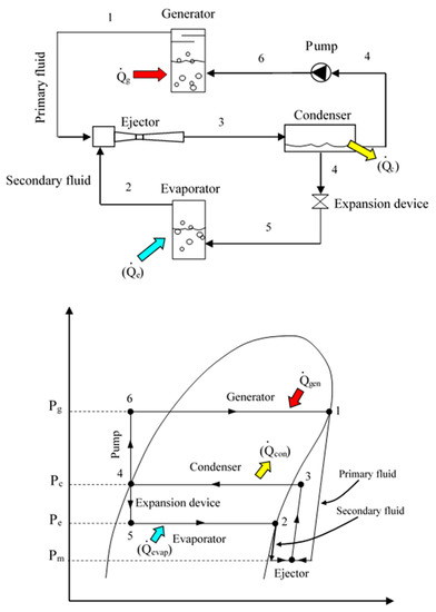
Figure 1.
The ejector refrigeration cycle and its refrigerant flow state.
From the ejector refrigeration system (seen in Figure 1), the ejector is the key equipment to produce the refrigeration effect. It uses the high pressure refrigerant called “primary fluid” to produce a low pressure region inside the mixing chamber which is connected to the evaporator. When the primary fluid is accelerated through the primary nozzle, the low pressure and low temperature fluid from the evaporator (called the “secondary fluid”) can entrain into the mixing chamber. This results in the production of refrigeration effect. The mass entrainment ratio (Rm) which is the ratio of the secondary mass flow rate to the primary mass flow rate is used to indicate the ejector performance. This Rm indicates the overall system performance of the ejector refrigeration system under various working conditions. Therefore, the ejector refrigeration system has been extensively investigated and discussed based on the variation in the Rm under various operating conditions. Some researchers have investigated the ejector refrigerator in an attempt to produce the maximum Rm. The main aims were to determine the optimal operating condition, Hamzaoui et al. [11], Narimani et al. [12], Fang et al. [13], Dong et al. [14], and to enhance the system performance via the careful design of the ejector geometries, Van Nguyen et al. [15], Thongtip and Aphornratana [16], Chen et al. [17]. In addition, due to the advantage of the CFD simulation technique, it has been extensively used to design and to optimize the ejector geometries. Besagni et al. [18], Zhang et al. [19], Allouche et al. [20], Zhang et al. [21] and Mahmoudian et al. [22] have implemented the CFD simulation to discuss the ejector performance influenced by the operatiing conditions. Their findings could support some phenomenon found from the experiments. This can help the researchers to explore the flow characteristics of the supersonic stream inside the ejector which is quite complicated.
For a certain operating temperature of the generator, evaporator and condenser, Van Nguyen et al. [15], Thongtip and Aphornratana [16], Chen et al. [17], have found experimentally that the key parameters to dominate the entire ejector performance are the ejector area ratio and primary nozzle area ratio. These parameters are the key to produce the Rm and the critical condensation temperature. Therefore, the ejector area ratio and primary nozzle area ratio were then optimized for a certain operating condition.
Another interesting point of the ejector refrigeration system is that many kinds of the working fluids (various refrigerants) or even water (steam-water) can be used to produce the refrigeration effect. Thus, many researchers have attempted to demonstrate the influence of the working fluid used on the entire system performance for a particular working condition. Some researchers, Chen et al. [23], Besagni et al. [24], Galindo et al. [25] have screened the working fluids for operating the ejector refrigeration system. Their interpretations were that the refrigerant types, HCFC (R141b, R123, R142b), HFO (R1233zd(E), R245fa, R1234yf) and hydrocarbon (R600a or propane) could be used for powering the ejector refrigerator with a heat source temperature of below 90 °C. More interestingly, a new kind of refrigerant, HFO-1234ze(E) was used as the working fluid for the ejector refrigeration system as proposed by Śmierciew et al. [26]. It was found experimentally that the heat source of below 75 °C could be used to drive the ejector refrigerator and provide an acceptable performance.
As mentioned above, the previous researches, both experiments and simulations, have demonstrated that the ejector refrigeration system has high potential to further develop for real air-conditioning applications. This is so that a reduction in the electrical energy for the refrigeration system is achieved while the cooling need or thermal comfort are still satisfied. Hence, to make the ejector refrigerator for commercial purposes, the practical performance, especially for demonstrating its ability to produce the thermal comfort conditions (an air-conditioning test performance), is highly required for performance assessments and economic assessment. This is to show whether the ejector refrigeration system is worthy of installation and to ensure that the payback period from installing refrigeration plant is as short as possible. This has encouraged some researchers to demonstrate the air-conditioning test performance of the ejector refrigerator.
Eames et al. [27], proposed the R245fa ejector refrigerator to produce the chilled water (temperature of 8–15 °C) for further use in the air conditioning application. Its nominal cooling load is 40 kW. It was driven by industrial waste heat (temperature of 90–100 °C). Varga et al. [28] constructed the prototype solar–driven ejector air conditioner. The prototype machine working with R600a was studied for the climate conditions of Portugal. It was operated as an air conditioner for a tested room (floor area 16 m2). Ruangtrakoon and Aphornratana [29] have proposed the ejector refrigeration system working as the air conditioner under Thailand’s climate (quite hot and humid). The working fluid used is steam. The condenser was cooled by cooling water produced by a cooling tower. The chilled water was produced. It was supplied to a fan-coil unit installed within the test room (floor area of 15 m2). The aim is to produce the thermal comfort condition under various operating conditions. However, for the warm ambient, the refrigerator requires a relatively high heat source temperature (110–120 °C) for overcoming the condensation pressure which is quite high. Hence, it may not be practical when the real heat source is applied to operate the air-conditioning plant. To fix such a problem, Thongtip and Aphornratana [30] have proposed the ejector refrigerator working with R141b to demonstrate the air-conditioning performance under various working conditions. It could be driven by hot water (temperature of 90–95 °C). It was found that the ejector refrigerator could efficiently operate as the air conditioner to produce the thermal comfort under Thailand’s environment. It provided an acceptable system COP which is up to 0.45.
The existing research has shown the feasibility of an ejector refrigerator in an actual air conditioning application. The prototype refrigeration machine could operate efficiently under various operating conditions while a reasonable system COP was achieved. More interestingly, the system COP of around 0.45–0.62 was achieved under the optimal working condition. Such the system COP is as high as that produced by the single effect absorption refrigerator (another type of TDR). The overall test results provided by the previous works have indicated the high potential of ejector refrigerator for practical use in air conditioning application. However, from the literatures, there are very few researches using the ejector refrigeration system as the air conditioner.
From the previous work of the authors [30], the prototype thermally driven ejector refrigerator working as air conditioner has been developed and the preliminary test based on the air-conditioning application has also been demonstrated. The feasibility of it in a real air-conditioning test under the warm ambient was proposed practically. The air-conditioned space temperature (Tair-cond) varied with the cooling load applied which ranged from 11 to 27 °C associated with the cooling load of 500 to 4500 W, respectively. However, the preliminary test has not yet considered how the variation in the heat source temperature and nozzle geometries will affect the ability to produce thermal comfort conditions. It is useful for being a reference case to assess the air conditioning performance when the ejector air conditioner is integrated with the real heat source such as a solar water heater, flue gas of combustion, industrial waste heat, etc. Such heat sources are available with the variation in the temperature which results in the overall air conditioning performance.
Furthermore, according to the author’s knowledge, the real air conditioning test of the ejector working as air conditioner which concentrates on the thermal comfort condition powered by various heat source temperatures has not been available from open literature. This indicates that there is still a lack of experimental work to investigate the real air conditioning performance of the ejector air conditioner. Even though there are several published papers in this research field, most of them focus on the cycle improvement via optimization of the ejector geometries by means of the experimental test bench and CFD simulation technique.
This paper proposes the air-conditioning performance of the ejector refrigerator-based air- conditioner (ERAC) under the actual working condition. The impacts of the heat source temperature, primary nozzle size and cooling load on the ability to produce the thermal comfort condition are discussed. The ERAC with the cooling capacity up to 4.5 kW is tested under various working conditions. It is operated as the water chiller to produce the chilled water temperature under various cooling loads. The produced chilled water is supplied to the fan-coil unit installed in the tested room (air-conditioned space) for producing thermal comfort conditions. The ERAC is driven by hot water whose temperature can be regulated precisely. This is to demonstrate the system performance under various heat source temperatures.
To demonstrate the actual working condition of the ERAC, the cooling water which is provided by the cooling tower under Thailand ambient is used to cool the condenser. The cooling load applied to the test room (air-conditioned space) is supplied by the air heater. Hence, the cooling load can be varied precisely for demonstrating the cooling performance. The results have shown that the ERAC operates efficiently which is driven by the hot water temperature of 90–98 °C and rejecting unwanted heat under the warm ambient. The system performance can vary significantly with the heat source temperatures, cooling load, primary nozzle sizes, and air-conditioned space temperature. By varying the hot water temperatures, the optimal performance (maximum system COP) is determined for a certain operating condition. Hence, the optimal hot water temperature is indicated based on the real operation. It is also found that the change in the working condition causes the optimal hot water temperature to be varied significantly. The air conditioning test results have demonstrated high potential to further using the ejector refrigeration system in the actual air conditioning application under the warm ambient driven by relatively low temperature heat source.
2. Ejector Refrigerator–Based Air Conditioner
The air-conditioning performance of an ejector refrigeration system working as real air conditioner which is driven by relatively low heat source temperature is demonstrated and impact of the operating conditions on the system performance is also assessed. Hence, the ejector refrigerator-based air conditioner (ERAC) is designed and constructed. The ERAC which has been developed by the previous work of the authors [30], was used to carry out the tests for discussions. The working fluid used in the refrigeration cycle is R141b. The reasons why R141b is still used for investigations are: it is a type of dry fluid which gives dry expansion process; it is available in Thailand at moderate cost; and it is a type of high boiling point substances at atmospheric pressure, therefore, it require moderate construction of the pressure vessels (cost savings). Even though new generation refrigerants such as R245fa and R1233zd(E) are currently available in Western countries they were not available in Thailand at the time of the investigations. According to the thermodynamic properties of R245fa and R1233zd(E), the feasibility of drop-in replacement for the R141b is possible. If the new generation refrigerants is made available in Thailand, drop-in replacement of R141b will be implemented by the authors. In this study, the ERAC was operated as the water chiller to produce the chilled water for operating the fan-coil unit to produce thermal comfort. This is so that the real air conditioning test can be investigated. Therefore, the system setup is divided into two main sections which are the refrigeration setup and air conditioning system setup. The details are later provided in Section 2.1 and Section 2.2, respectively.
2.1. The Details of an Ejector Refrigerator—Based Air Conditioner
The photograph and schematic view of the ERAC are presented in Figure 2a,b. It comprises a generator, an evaporator, an ejector, a condenser, a receiver tank, a hot water storage tank, a chilled water tank and a refrigerant feed pump. The ERAC is designed so that the ejector and other necessary equipment to be easily changed with each other. This allows the performance of ERAC under various ejector geometries to be investigated clearly.
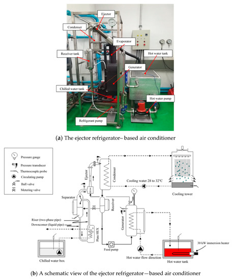
Figure 2.
Photograph and schematic diagram of the ejector refrigerator—based air conditioner.
The generator was the water–heated type. Its vessel was modified from a plate heat exchanger. The generator was powered by the hot water under various temperatures. In this case, the hot water was produced by the heaters with the rate power up to 15 kW. The refrigerant was heated when the hot water was pumped through the generator vessel by the hot water circulating pump (model SCX40–80N, SALMSON). This pump can produce the flow rate up to 850 L·min−1. Under the designed working condition, the differential temperature of hot water between inlet and outlet port of 2–3 °C is made possible while the heat rate up to 15 kW is achieved. This indicates the efficient heat transfer at the generator. The hot water storage tank was made of SUS-304 and well–insulated with polystyrene foam. Its capacity is 40 L. Three immersion heaters with maximum power of 27 kW was used to generate heat for investigations. The hot water was pumped through the generator at the bottom for ensuring that the generator was flooded with the hot water. This is to provide an efficient heat transfer process.
The evaporator comprises a plate heat exchanger and a liquid-vapour separator which aims to produce natural circulation (Thermo-syphon). The evaporator was connected with the insulated box which is considered as the cold storage tank for further use in the air conditioning test. The heat exchanger (model B12H, SWEP) was used to exchange heat between refrigerant and water. Hence, the chilled water under various working conditions can be produced for air conditioning purposes. The liquid-vapour separator was located over the plate heat exchanger of 1.2 m to enhance the natural circulation when producing the refrigerating effect. The liquid-vapour separator was made of a 3-inch SUS-304 tube. Its length is 45 cm. Three baffle plates were installed at the upper part to separate the liquid being carried over with vapour.
The condenser was modified from a plate heat exchanger (SWEP model CBE–B8fx64). It was cooled by the cooling water which was produced by a cooling tower. Under the Thailand ambient, the cooling water temperature varies ranging from 27 °C to 33 °C. The cooling water was circulated to the condenser at the bottom part so that the condenser was flooded by the cooling water. This make the condensation pressure as low as possible. The liquefied refrigerant was accumulated within the receiver tank. The refrigerant level inside the receiver tank was observed by the sight glass. This allows the refrigerant flow rate to be controlled easily and efficiently. Part of the liquefied refrigerant was pumped into the generator via a refrigerant feed pump which was driven by a 24VDC–motor (250 W). Meanwhile, the remainder expanded through the adjustable expansion valve into the evaporator to produce a refrigerating effect. The metering valve manufactured by SWAGELOK (Solon, OH, USA) was used as the expansion valve in which the precise control of the refrigerant flow rate is achieved.
The type–k thermocouples with an uncertainty of ±0.25 °C was used to measure the temperature value at the relevant points. The digital temperature controller with PID controller was used to regulate the hot water temperature so that the desired value is obtained during the tests. The pressure at points of interest are measured by the pressure transducers and pressure gauges. The uncertainty of the pressure transducer is 1.0% of full scale. The liquid refrigerant levels contained within the evaporator, generator and receiver tank were monitored by the sight glass. Therefore, the balancing of the refrigerant flow rate through the cycle can be easily controlled.
2.2. The Air Conditioning Test Setup
As explained earlier, the chilled water produced by the refrigerator is later used as the heat transfer medium to produce the cold air for air conditioning purposes. The requirements and setup for the air conditioning test are provided in this section. A schematic diagram of the air conditioning test is depicted in Figure 3. The equipment used for this test includes a test room, a fan–coil unit, an air heater, and an air blower. The test room has a floor area of 15.3 m2. All wall surfaces, floor and ceiling are the double wall type. The polystyrene insulator was inserted between the outer surface and inner surface to prevent heat loss and gain of the test room.
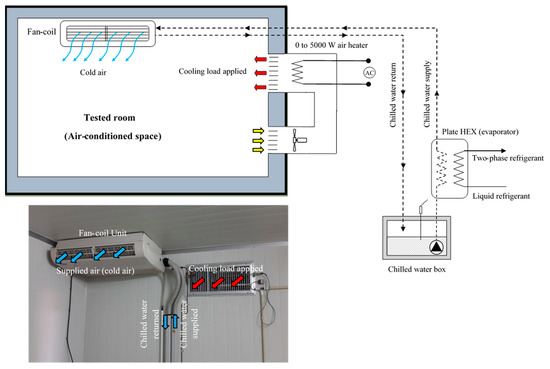
Figure 3.
A schematic view of the air-conditioning test.
The fan–coil unit was a ceiling type. The chilled water produced by the ERAC was circulated to the fan–coil unit via the magnetic–coupling centrifugal pump (SANSO, model PMD 1511). The volume flow rate of around 0.167 kg s−1 was achieved. The chilled water temperature at inlet and outlet of the fan–coil was observed.
The cooling load was generated by an air heater which was later applied to the air–conditioned space. The heat load (cooling load) was supplied to the air–conditioned space by circulating air passing through the air heater. The circulation of air is applied via an air blower. The cooling load is adjusted precisely by means of the variable transformer (0–220 VAC). Therefore, during the test, thermal load (cooling load) is initially transferred to the chilled water as the air passing through the fan-coil unit, and later, the thermal load transferred to the evaporator of the ERAC. Hence, the steady state operation is required for a particular test case so that the heat balance of the test system is achieved. Therefore, the heat load applied to the test room (air-conditioned space) is exactly identical to the cooling load absorbed by the refrigerator. Hence, the cooling load applied for investigations can be controlled precisely by controlling the heater power.
In this present work, the heat balance of the tested system was implemented for ensuring that the steady state operation is reached. This is so that the tested results was recorded accurately. For a particular test, the heat balance of the test system is indicated by comparison of the cooling load applied by air heater with the heat absorbed by the fan-coil unit. It must be balanced with each other. In addition, the temperature at points of interest are observed simultaneously. At the steady state operation, the temperature at points of interest are kept constant (independent of time).
2.3. The Ejector and Primary Nozzle Geometries
The ejector and primary nozzles geometries were designed based on one-dimensional compressible flow theory (1-D model) which was proposed by Keenan [31]. It was designed to produce the cooling load of 4.5 kW. Two primary nozzles were tested with one fixed mixing chamber geometry. The optimization of the ejector geometries (ejector area ratio and primary nozzle area ratio) to obtain its best performance has previously been implemented by the authors as seen in Thongtip and Aphornratana [16] and Thongtip and Aphornratana [30]. The geometrical drawing of the ejector including a mixing chamber, an ejector throat, a subsonic diffuser and the primary nozzles is shown in Figure 4.
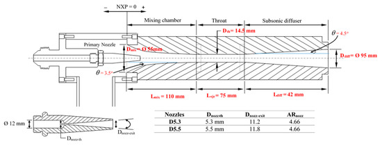
Figure 4.
The geometrical drawing of the ejector and primary nozzles.
Two primary nozzles were designed based on the ARnozz of 4.66 which aims to create the nozzle exit Mach number of 2.5. This ARnozz value has been proven to be consistent with the generator working temperature of 90–98 °C and with the cooling temperature of 8–16 °C. This is because the ejector refrigerator can work stably under a relatively low temperature heat source while the cooling temperature is consistent with the air conditioning application. The theoretical primary nozzle area ratio under various nozzle’s exit Mach numbers can be estimated as:
In this case, two primary nozzles which had different throat diameters of 5.3 and 5.5 mm, respectively were manufactured. However, they had identical primary nozzle area ratios which means their ability to produce the evaporator temperature is identical. Two such primary nozzles were investigated with one ejector’s mixing chamber with throat diameter of 14.5 mm. Hence, the ejector area ratio of 6.3 and 7.9 were considered for performance assessments. Such value of the ejector area ratio has been proven to be consistent with the required operating condition.
2.4. Data Analysis and Instrumentation
The overall system performance of the ERAC is indicated by the system COP. It is able to be calculated when the parameters of interest such as temperature, pressure, flow rate, and electricity consumption are known. The system COP of the ERAC is calculated by Equation (2):
The cooling load can be calculated by Equation (3)
Alternatively, the cooling load can be estimated by electricity consumption at the air heater (simulating the cooling load) as stated by Equation (4).
The heat rate required for operating the generator under various working conditions is calculated by Equation (5)
The electricity consumption for all liquid pumped can be calculated by Equation (6).
To obtain the reasonable accurate temperature values, a type-k thermocouple was calibrated carefully before implementing the tests. The accurate value of the temperature was achieved by comparing it with a high precision mercury thermometer. The uncertainty of the thermocouple obtained from the temperature calibrations is ±1.5% of the read value.
All pressure transducers were calibrated precisely before implementing the tests. The correct value of the vacuum pressure was referenced by absolute zero pressure reference. This was made possible by using the double stage liquid ring vacuum pump. The positive pressure reference was referenced by using the dead weight tester. The atmospheric pressure reference was achieved by using a high precision mercury barometer. The uncertainty of the pressure transducers was ±1.0% of full scale.
The volume flow rate of the chilled water flowing through the fan-coil unit was monitored by the rotameter with the uncertainty of 1.0% of full scale. The cooling load which is applied by the air heater was measured precisely by a power meter manufactured by HIOKI, model PQ3100 with uncertainty of ±0.2% of full scale. A variable transformer was used to regulate the voltage supplied to the heater; hence, the cooling load could be varied precisely during the tests.
During the operation, data acquisition (model GP10-1-E-F/UC20, Yokokawa) with uncertainty of ±0.15% of the read values was used to monitor and to record the temperature values at the point of interest. The transient operation and steady operation of the system are made possible by monitoring this data acquisition. This makes the system operation and the collecting of data reliable.
The uncertainty of the system COP are determined by the uncertainty analysis in which the uncertainty of the relevant parameters affect the read value of the system COP. It can be calculated by Equation (7) which is supported by [32].
From the uncertainty analysis, the uncertainty of the system COP is ±3.25%.
3. Results and Discussion
3.1. Performance of the Ejector Refrigerator—Based Air Conditioner
3.1.1. Heat Rate and Electricity Consumption Required for Operation
The ejector refrigeration system is the thermally driven machine which mainly consumes heat to produce useful refrigeration. This section demonstrates the heat rate and electricity consumption of the necessary equipment required for operating the ERAC when working with different hot water temperatures and primary nozzle sizes. To demonstrate this, the primary nozzles D5.3 and 5.5 were tested. The hot water temperature was increased from 86 to 100 °C.
Figure 5 depicts the heat rate required for operating the generator under various hot water temperatures (Thot) when using two primary nozzles. The electricity consumption required for the chilled water pump, the hot water pump, refrigerant pump, cooling tower fan and cooling tower pump is presented in Table 1. It is found from Figure 5 and Table 1 that for a particular primary nozzle, the heat rate increases with increasing Thot while the electricity consumption required of the other equipment is approximately constant (due to almost all the pumps and fan being operated at the constant speed except for the refrigerant pump which increases slightly with increasing Thot). Based on the compressible flow theory which is used to design the primary nozzle, increasing the generator pressure (increasing Thot) causes producing a higher primary mass flow rate. Hence, a higher heat supplied is required for operating the generator at the same Thot. It is also found that for a certain value of Thot, a bigger primary nozzle throat requires a higher heat rate for operation. In this case, using a bigger primary nozzle throat provides a larger flow area for the primary stream, resulting in producing a higher mass flow rate at identical Thot.
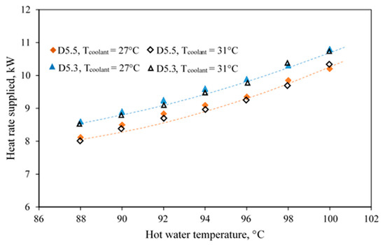
Figure 5.
The heat rate required for operation influenced by different primary nozzles.

Table 1.
Electricity and thermal energy consumption under various hot water temperatures.
It is interesting to see that as the cooling water temperature increases from 27 to 31 °C, there is no impact on the heat rate required for operation as seen in Figure 5. This is because the heat rate under various Thot does not depend on the variation in the condenser pressure. The change in the cooling water temperature causes the condensation temperature to be changed significantly. This causes the ejector’s discharge pressure to vary significantly. However, the heat rate required for operation is maintained constant. This implies that the variation of the condensation pressure has no influence on the heat rate required for operation. This phenomenon is consistent with the designed theory of the converging-diverging nozzle. The downstream condition of the converging-diverging nozzle does not give impact on the critical mass flow rate when the primary nozzle is always choked. The mass flow rate is only varied when the stagnation condition (Thot) and throat diameter are changed.
The results proposed in this section have shown that when the ejector refrigerator based air conditioner is operated at higher Thot or a larger primary nozzle throat size, it requires a higher heat rate for operation. However, the cooling performance (cooling temperature and cooling) has not been discussed. This will be detailed in the next section.
3.1.2. The Air-Conditioned Space Temperature Against the Cooling Loads
The cooling performance of the ERAC is demonstrated and performance assessment is provided in this section. The test was implemented by fixing the Thot at 94 °C while the cooling water temperature supplied to cool the condenser was around 30 °C. Two primary nozzles, D5.3 and D5.5, were investigated. The cooling loads were varied ranging from 1500 to 4500 W. The room temperature or air-conditioned space temperature under various cooling loads was observed. The tested results were collected under the steady state operation. The results are depicted in Figure 5 and Table 2.
Table 2.
The temperature and pressure at points of interest.
In this present work, the tested method is aimed to demonstrate the performance of the ERAC based on the real operation. It is evident that for a particular working condition, the condensation pressure always reaches a certain value because the cooling water temperature supplied to cool the condenser is limited to a certain value associated with the ambient. Therefore, the parameter of interest during the test is the cooling temperature under various cooling loads. This will produce different Tair-cond (cooling temperature). This test method is called “alternative test method” as proposed by Thongtip and Aphornratana [33].
The performance curve proposed in this present work is significantly different from the traditional performance curve (COP or Rm is plotted against the condensation pressure) which is extensively used by many researchers. This is one of the new information of this present work which has not been available from the open literatures. For the traditional performance curve, the choked flow of secondary fluid stream (on-design) can be indicated when the condensation pressure is below its critical value while the unchoked flow of the secondary fluid stream (off-design) is also indicated when the condensation pressure is between critical value and breakdown value. It is seen that both on-design and off-design operations must be indicated by the change in the condenser pressure. This is possible only when using experimental test bench in Laboratory which is not consistent with the real operation in which the condensation pressure is limited to a certain value depending on the ambient condition. Thus, the lowest possible cooling temperature at a certain cooling load is the main parameters of interest which is to demonstrate the real operation of the ERAC. Hence, this present work does not consider both on-design and off-design operations due to the different perspectives of problems based on the different test methods. The refrigeration machine is considered to be workable as long as it still produces the refrigerating effect at lowest possible evaporator temperature. Therefore, performance of the ERAC focuses on the capability to produce the cooling temperature under a certain cooling load.
It is found from Figure 6 that for a particular primary nozzle, the Tair-cond increases when increasing the cooling load. It is also found that the Tair-cond under a certain cooling load reduces when a larger primary nozzle throat is used. It can be seen from Table 2 that the evaporating temperature (Tevap) increases with increasing the cooling load which is consistent with the Tair-cond and Tchill. This is because they are operated together as a single unit to produce the cold air (or Tair-cond) for air-conditioning test. However, there are two stages of the heat transfer processes during the air-conditioning test: first, it occurs at the fan-coil unit in which air is cooled by the chilled water; and second, it occurs at the evaporator in which the chilled water is cooled by the refrigerant within the evaporator. These two heat transfer processes are the cause of producing the difference in temperature between evaporator and air-conditioned space. For the condensation pressure, it increases slightly when increasing the cooling load as seen in Table 2. This is because a higher unwanted heat is being rejected at the condenser while the cooling water is supplied at the constant temperature.
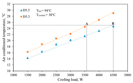
Figure 6.
Variations of the Tair-cond with the cooling load.
According to the thermal comfort condition in which the Tair-cond is required at around 25 °C, the ERAC equipped with the primary nozzle D5.5 can absorb the cooling load at around 4500 W (point B) while that equipped with D5.3 can absorb the cooling load at around 3600 W (point A). This is shown by the dashed line in Figure 6. Therefore, it seems a larger primary nozzle throat provides a better performance. Hence, the primary nozzle D5.5 is preferable in which it is flexible for real operation. The reason why the nozzle D5.3 produces a relatively high Tair-cond is that at the same cooling load, the primary stream momentum produced by a smaller primary nozzle is less than that produced by a larger primary nozzle. Therefore, the primary momentum (operating at the same hot water temperature) is inadequate to create its best shear mixing layer development between primary and secondary fluid. As a result, the secondary fluid pressure (corresponding to the evaporator pressure) becomes higher as compared with that using a larger nozzle. Therefore, the evaporator temperature produced by nozzle D5.3 is higher than that produced by nozzle D5.5.
As discussed previously in Section 3.1, using a bigger primary nozzle throat must require a higher heat rate for operating the generator at identical Thot. This results in producing a lower system COP. Figure 7 shows the system COP against cooling load as working with two primary nozzles. It can be seen that at the same cooling loads, the system COP produced by nozzle D5.3 is slightly higher than that produced by D5.5. This is because the heat rate required for operating the nozzle D5.3 is lower than that required for nozzle D5.5. However, for the air conditioning application in which the cooling temperature (Tair-cond) is the main purpose, the system working with nozzle D5.5 is preferable for practical use. This is due to it providing a much lower air-conditioned space temperature at identical cooling load as shown in Figure 5 while the system COP is not much different.
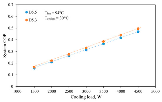
Figure 7.
The system COP against cooling loads influenced by primary nozzles.
Overall, this section has shown the cooling performance at identical Thot. The ERAC could operate stably and provided an acceptable performance. The Tair-cond increases when increasing cooling loads. However, at the thermal comfort condition (Tair-cond = 25 °C), which is the main achievement for any air conditioners in real applications, it is demonstrated at fixing Thot = 94 °C. In other words, the performance of the ERAC is specifically provided at a certain value of the hot water temperature. The performance of the ERAC under a wider range of the heat source will be provided in the next section.
3.2. Optimal Performance of the Ejector Refrigerator Based Air-Conditioner Operated at Thermal Comfort Condition
3.2.1. Impact of the Hot Water Temperature on System Performance
In this test, the Tair-cond is maintained at 25 °C which is consistent with the thermal comfort condition. In practice, the cooling load can vary with the daytime period and the number of occupants. Hence, it will affect the cooling performance of the ERAC. This section proposes the optimal performance for producing the thermal comfort condition of the ERAC when the Thot is varied.
During the test, the Thot was varied from 86 to 100 °C. The cooling water used to cool the condenser was supplied at around 31 °C. The primary nozzle, D5.5, was used for demonstration. For a certain value of the Thot, the cooling load was varied precisely to obtain the desired air-conditioned space temperature (Tair-cond = 25 °C). The results are illustrated in Figure 8.
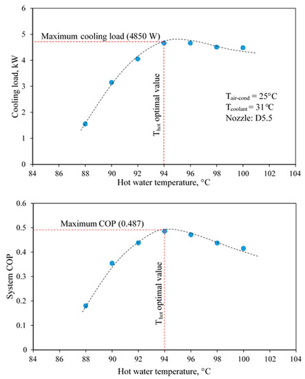
Figure 8.
The cooling load and system COP against the hot water temperature.
It is evident from Figure 8 that when the Tair-cond is held constant at 25 °C, an increase in the cooling load is found as the hot water temperature is increased continuously, until it reaches its maximum value. Later, an increase in the Thot is the result of producing a lower cooling load. However, increasing the Thot causes to produce a higher primary fluid flow rate which must require a higher heat rate for the generator operation. Thus, the system COP is initially increased as the hot water temperature increases until it reaches its maximum value. It is obviously seen from Figure 8 that when the hot water reaches 94 °C, the ERAC can produce a maximum system COP of 0.487 and cooling load of 4850 W. Therefore, this hot water temperature can be considered as the optimal value for the ERAC. This means there is no advantage in using a too high heat source temperature. This phenomenon indicates that the ERAC should be operated at the optimal Thot for achieving its best performance.
At the Thot below the optimal value, it is believed that the secondary stream is no-longer choked. This is due to the momentum of the primary stream being inadequate to produce its best mixing process of the two fluid streams. Therefore, the secondary stream cannot perform the choked flow condition. On the other hand, when the Thot reaches the optimal value, the primary stream momentum is adequate to make its best mixing process, causing it to produce a maximum secondary flow rate. This is because the secondary fluid stream is being choked at the minimum required primary flow rate.
If the Thot is higher than the optimal value, a decrease in the cooling load is found even when the primary stream momentum continues to increase. In such a case, the secondary stream is still choked as supported by Ruangtrakoon and Thongtip [34] and Yapici [35]. A reduction in the secondary flow rate is due to a smaller flow area for the secondary fluid stream. This is due to the fact that a higher primary fluid flow rate occupies a larger flow area within the mixing chamber. As a result, the secondary mass flow rate decreases even when the primary stream momentum is higher than the minimum required value.
As discussed above, it has been shown that the heat source temperature is important to the ability to produce the cooling load of the ERAC. It has also been shown that using a too high heat source temperature is not desirable for operation because it has a negative impact on the system COP. This indicates that the ERAC working on the actual scenario should be powered by the optimal heat source temperature. Since the air conditioning test of the ERAC under hot climate has not been available from the open literature this present work first demonstrates the actual performance of the ERAC. However, for a wider range of operating conditions, further investigation is required. This will be proposed in the next section.
3.2.2. The Optimal Performance Influenced by the Primary Nozzle
As discussed in the previous section, the hot water temperature used to drive the ERAC should be kept at the optimal value to achieve its best performance (maximum system COP). However, if the primary nozzle is changed, it will significantly affect the optimal point of operation. This will be demonstrated in this section. To demonstrate the optimal performance influenced by the primary nozzle, the test method as previously implemented in Section 3.2.1 was repeated. Two primary nozzles, D5.3 and D5.5, were tested under various hot water temperatures. The Tair-cond was maintained at 25 °C which is the thermal comfort condition. The cooling load was varied precisely to obtain the constant Tair-cond. The cooling water temperature of 31 °C was supplied to cool the condenser. The results are depicted in Figure 9.
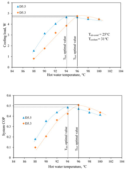
Figure 9.
The cooling load and system COP against Thot influenced by primary nozzles.
It is evident from Figure 9 that when the primary nozzle is changed, the optimal value of the Thot increases from 94 to 96 °C. However, at the optimal point of operation, a smaller primary nozzle (D5.3) can produce a slightly higher cooling load while the heat rate required for operation is reduced. This causes to produce a higher system COP even when the optimal hot water temperature is higher. However, for a practical use of the ERAC, the heat source temperature should be as low as possible while the cooling purpose is still satisfied. This implies that using the primary nozzle with a bigger throat seems to be the most promising primary nozzle for operation.
The reason why the smaller primary nozzle needs a higher Thot to produce the optimal performance is that a lower primary flow rate is generated at identical Thot, resulting in a lower primary stream momentum. This lower momentum is inadequate for producing the best mixing process at lower hot water temperature which results in producing a lower secondary flow rate. This will mitigate the ability to produce the cooling load. Therefore, a smaller nozzle requires a higher hot water temperature to produce its optimal performance. This phenomenon indicates that the primary nozzle should be designed carefully associated with the temperature of the heat source in order to achieve the optimal performance.
3.2.3. The Optimal Performance Influenced by the Air-Conditioned Space Temperature
In this section, the optimal hot water temperature under various Tair-cond is determined. This is to demonstrate the flexible use of the ERAC in real operation in which the cooling temperature is required at different levels. In some situations, the Tair-cond must vary associated with the cooling purposes. Therefore, the optimal value of the Thot under various cooling loads should be studied for discussion. To demonstrate this impact, the Tair-cond was held constant at different values while the Thot was varied to determine the optimal Thot. The primary nozzle D5.5 was used for demonstration. The cooling load was varied to obtain the thermal comfort. The results are presented in Figure 10.
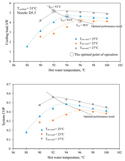
Figure 10.
The cooling load and system against Thot influenced by the air-conditioned temperatures.
It is seen that an increase in the Tair-cond requires a lower Thot to produce the best performance. At the optimal operation, the cooling load and system COP increase when the Tair-cond is increased. The reason is that at a higher Tair-cond, the evaporating pressure, which is the stagnation state of the secondary fluid stream, is increased. Thus, a lower primary stream momentum is required to produce the choked flow of the secondary fluid. Therefore, a lower Thot is required for producing the optimal performance which results in the system COP being increased.
As discussed above, the ERAC can work efficiently under a range of cooling temperatures (various air-conditioned temperatures). However, the Thot must vary simultaneously to achieve the optimal performance for a certain Tair-cond. This is to achieve the efficient energy use. The results have also shown that the use of improper Thot provides a negative impact to the system operation. Thus, the hot water temperature should be varied precisely to achieve the optimal performance when the Tair-con is varied.
4. Conclusions
The air-conditioning test performance of the ejector refrigerator based air-conditioner (ERAC) was proposed under various hot water temperatures, primary nozzle sizes, cooling loads and air-conditioned space temperatures. This was to demonstrate the practical use of the ERAC in a real air-conditioning application under the warm ambient while the system was driven by a relatively low temperature heat sources. The optimal performance of the ERAC working under the thermal comfort condition (Tair-con = 25 °C) was demonstrated. This was achieved when the hot water temperature was varied. It was evident that the optimal performance varied significantly with variations in the working conditions. The findings of this present work are summarized as follows:
- For a certain hot water temperature and primary nozzle used, an increase in the cooling load caused the air-conditioned space temperature to be increased. However, the cooling load must not be too high when the thermal comfort condition is considered.
- For a certain hot water temperature, when the primary nozzle throat was enlarged, a decrease in the Tair-con was found at identical cooling load. However, using a bigger primary nozzle caused a decrease in the system COP.
- For operating at the thermal comfort condition, initially, increasing the hot water resulted in increasing the system COP until it reached its maximum value (optimal performance). Later, the system COP decreased when the hot water continued to increase. Therefore, the optimal heat source for this particular working condition was determined.
- When operating at the thermal comfort condition, enlarging the primary nozzle throat required a lower Thot to produce the optimal point of operation. However, a slight decrease in the system COP was found.
- A change in the air-conditioned space temperature significantly affected the optimal performance. It was evident that the optimal performance of the ERAC was achieved with a lower Thot and vice versa.
The air-conditioning tests indicated the high potential of the ERAC for real operation. The results is useful for being a reference case to further develop the ejector refrigeration system for practical use. Hopefully, the information provided in this present work will be useful for the researchers who attempt to develop the ejector based air conditioner for practical use.
Author Contributions
Conceptualization, T.T. and N.R.; methodology, T.T. and N.R.; formal analysis, T.T. and N.R.; investigation, T.T.; resources, T.T.; data curation, T.T. and N.R.; writing—original draft preparation, T.T. and N.R.; writing—review and editing, T.T. and N.R. Both authors have read and agreed to the published version of the manuscript.
Funding
This research was funded by King Mongkut’s University of Technology North Bangkok. Contract no. KMUTNB-64-KNOW-38.
Institutional Review Board Statement
Not applicable.
Informed Consent Statement
Not applicable.
Data Availability Statement
Not applicable.
Conflicts of Interest
The authors declare no conflict of interest.
Nomenclatures
| Symbol | |
| ARejector | The area ratio of the ejector |
| ARnozzle | The area ratio of the primary nozzle |
| COP | Coefficient of Performance |
| D | Diameter of the relevant parameters (mm) |
| L | Length of the relevant parameters |
| The mass flow rate of the relevant parameters (kg s−1, kg min−1) | |
| NXP | The Nozzle Exit Position (mm) |
| P | The pressure value of the relevant parameters (kPa) |
| Qcon | Condensation heat rejected at the condenser (kW) |
| Qcool | Cooling load produced at the evaporator (kW) |
| Qgen | Heat required for the generator operation (kW) |
| Rm | The mass entrainment ratio of the ejector |
| T | The temperature value of the relevant parameters (°C) |
| Subscripts | |
| air-cond | Relevant parameter for the air-conditioned space |
| chill | Relevant parameter for the chilled water |
| cool | Relevant parameter at the cooling tower |
| con | Relevant parameter at the condenser |
| diff | Relevant parameter at the subsonic diffuser |
| fan | Relevant parameter at the cooling tower fan |
| ej-th | Relevant parameter at the ejector throat |
| evap | Relevant parameter at the evaporator |
| gen | Relevant parameter at the generator |
| hot | Relevant parameter at the hot water |
| nozz-exit | Relevant parameter the primary nozzle exit |
| nozz-th | Relevant parameter at the primary nozzle throat |
| p | Relevant parameter for mechanical pump |
| ref | Relevant parameter for the refrigerant |
References
- Yinhai, Z.; Jiang, P. Hybrid vapor compression refrigeration system with an integrated ejector cooling cycle. Int. J. Refrig. 2012, 35, 68–78. [Google Scholar]
- Fong, K.F.; Lee, C.K.; Chow, T.T. Improvement of solar-electric compression refrigeration system through ejector-assisted vapour compression chiller for space conditioning in subtropical climate. Energy Build. 2011, 43, 3383–3390. [Google Scholar] [CrossRef]
- Sánchez, D.; Catalán-Gil, J.; Cabello, R.; Calleja-Anta, D.; Llopis, R.; Nebot-Andrés, L. Experimental analysis and optimization of an R744 transcritical cycle working with a mechanical subcooling system. Energies 2020, 13, 3204. [Google Scholar] [CrossRef]
- Xia, Y.; Jiangzhou, S.; Zhang, X.; Zhang, Z. Steady-State Performance Prediction for a Variable Speed Direct Expansion Air Conditioning System Using a White-Box Based Modeling Approach. Energies 2020, 13, 4757. [Google Scholar] [CrossRef]
- Lin, C.; Xu, C.; Yue, B.; Jiang, C.; Omori, H.; Deng, J. Experimental study on the separator in ejector-expansion refrigeration system. Int. J. Refrig. 2019, 100, 307–314. [Google Scholar] [CrossRef]
- Jeon, Y.; Jung, J.; Kim, D.; Kim, S.; Kim, Y. Effects of ejector geometries on performance of ejector-expansion R410A air conditioner considering cooling seasonal performance factor. Appl. Energy 2017, 205, 761–768. [Google Scholar] [CrossRef]
- Pottker, G.; Hrnjak, P. Ejector in R410A vapor compression systems with experimental quantification of two major mechanisms of performance improvement: Work recovery and liquid feeding. Int. J. Refrig. 2015, 50, 184–192. [Google Scholar] [CrossRef]
- Jeon, Y.; Kim, H.; Ahn, J.H.; Kim, S. Effects of Nozzle Exit Position on Condenser Outlet Split Ejector-Based R600a Household Refrigeration Cycle. Energies 2020, 13, 5160. [Google Scholar] [CrossRef]
- Lillo, G.; Mastrullo, R.; Mauro, A.W.; Trinchieri, R.; Viscito, L. Thermo-economic analysis of a hybrid ejector refrigerating system based on a low grade heat source. Energies 2020, 13, 562. [Google Scholar] [CrossRef]
- Bai, L.; Liu, S.; Ye, Z.; He, M. Investigation on the performance of R1234ze (E) in absorption refrigeration and ejection refrigeration systems. Appl. Therm. Eng. 2019, 161, 114120. [Google Scholar] [CrossRef]
- Hamzaoui, M.; Nesreddine, H.; Aidoun, Z.; Balistrou, M. Experimental study of a low grade heat driven ejector cooling system using the working fluid R245fa. Int. J. Refrig. 2018, 86, 388–400. [Google Scholar] [CrossRef]
- Narimani, E.; Sorin, M.; Micheau, P.; Nesreddine, H. Numerical and experimental investigation of the influence of generating pressure on the performance of a one-phase ejector installed within an R245fa refrigeration cycle. Appl. Therm. Eng. 2019, 157, 113654. [Google Scholar] [CrossRef]
- Fang, Y.; Croquer, S.; Poncet, S.; Aidoun, Z.; Bartosiewicz, Y. Drop-in replacement in a R134 ejector refrigeration cycle by HFO refrigerants. Int. J. Refrig. 2017, 77, 87–98. [Google Scholar] [CrossRef]
- Dong, J.; Wang, W.; Han, Z.; Ma, H.; Deng, Y.; Su, F.; Pan, X. Experimental investigation of the steam ejector in a single-effect thermal vapor compression desalination system driven by a low-temperature heat source. Energies 2018, 11, 2282. [Google Scholar] [CrossRef]
- Van Nguyen, V.; Varga, S.; Soares, J.; Dvorak, V.; Oliveira, A.C. Applying a variable geometry ejector in a solar ejector refrigeration system. Int. J. Refrig. 2020, 113, 187–195. [Google Scholar] [CrossRef]
- Thongtip, T.; Aphornratana, S. An experimental analysis of the impact of primary nozzle geometries on the ejector performance used in R141b ejector refrigerator. Appl. Therm. Eng. 2017, 110, 89–101. [Google Scholar] [CrossRef]
- Chen, J.; Havtun, H.; Palm, B. Investigation of ejectors in refrigeration system: Optimum performance evaluation and ejector area ratios perspectives. Appl. Therm. Eng. 2014, 64, 182–191. [Google Scholar] [CrossRef]
- Besagni, G.; Mereu, R.; Chiesa, P.; Inzoli, F. An Integrated Lumped Parameter-CFD approach for off-design ejector performance evaluation. Energy Convers. Manag. 2015, 105, 697–715. [Google Scholar] [CrossRef]
- Zhang, G.; Dykas, S.; Li, P.; Li, H.; Wang, J. Accurate condensing steam flow modeling in the ejector of the solar-driven refrigeration system. Energy 2020, 212, 118690. [Google Scholar] [CrossRef]
- Allouche, Y.; Bouden, C.; Varga, S. A CFD analysis of the flow structure inside a steam ejector to identify the suitable experimental operating conditions for a solar-driven refrigeration system. Int. J. Refrig. 2014, 39, 186–195. [Google Scholar] [CrossRef]
- Zhang, G.; Dykas, S.; Yang, S.; Zhang, X.; Li, H.; Wang, J. Optimization of the primary nozzle based on a modified condensation model in a steam ejector. Appl. Therm. Eng. 2020, 171, 115090. [Google Scholar] [CrossRef]
- Mahmoudian, J.; Mazzelli, F.; Rocchetti, A.; Milazzo, A. A heat-powered ejector chiller working with low-GWP fluid R1233zd (E)(Part2: Numerical analysis). Int. J. Refrig. 2020, 121, 216–227. [Google Scholar] [CrossRef]
- Chen, J.; Havtun, H.; Palm, B. Screening of working fluids for the ejector refrigeration system. Int. J. Refrig. 2014, 47, 1–14. [Google Scholar] [CrossRef]
- Besagni, G.; Mereu, R.; Di Leo, G.; Inzoli, F. A study of working fluids for heat driven ejector refrigeration using lumped parameter models. Int. J. Refrig. 2015, 58, 154–171. [Google Scholar] [CrossRef]
- Galindo, J.; Dolz, V.; García-Cuevas, L.M.; Ponce-Mora, A. Numerical evaluation of a solar-assisted jet-ejector refrigeration system: Screening of environmentally friendly refrigerants. Energy Convers. Manag. 2020, 210, 112681. [Google Scholar] [CrossRef]
- Śmierciew, K.; Gagan, J.; Butrymowicz, D.; Łukaszuk, M.; Kubiczek, H. Experimental investigation of the first prototype ejector refrigeration system with HFO-1234ze (E). Appl. Therm. Eng. 2017, 110, 115–125. [Google Scholar] [CrossRef]
- Eames, I.W.; Milazzo, A.; Paganini, D.; Livi, M. The design, manufacture and testing of a jet-pump chiller for air conditioning and industrial application. Appl. Therm. Eng. 2013, 58, 234–240. [Google Scholar] [CrossRef]
- Varga, S.; Oliveira, A.C.; Palmero-Marrero, A.; Vrba, J. Preliminary experimental results with a solar driven ejector air conditioner in Portugal. Renew. Energy 2017, 109, 83–92. [Google Scholar] [CrossRef]
- Ruangtrakoon, N.; Aphornratana, S. Development and performance of steam ejector refrigeration system operated in real application in Thailand. Int. J. Refrig. 2014, 48, 142–152. [Google Scholar] [CrossRef]
- Thongtip, T.; Aphornratana, S. Development and performance of a heat driven R141b ejector air conditioner: Application in hot climate country. Energy 2018, 160, 556–572. [Google Scholar] [CrossRef]
- Keenan, J.H. An investigation of ejector design by analysis and experiment. J. Appl. Mech. 1950, 17, 299. [Google Scholar]
- Thongtip, T.; Aphornratana, S. An alternative analysis applied to investigate the ejector performance used in R141b jet-pump refrigeration system. Int. J. Refrig. 2015, 53, 20–33. [Google Scholar] [CrossRef]
- Coleman, H.W.; Steele, W.G. Experimentation, Validation, and Uncertainty Analysis for Engineers, 4th ed.; John Wiley Sons: Hoboken, NJ, USA, 2018. [Google Scholar]
- Ruangtrakoon, N.; Thongtip, T. An experimental investigation to determine the optimal heat source temperature for R141b ejector operation in refrigeration cycle. Appl. Therm. Eng. 2020, 170, 114841. [Google Scholar] [CrossRef]
- Yapici, R. Experimental investigation of performance of vapor ejector refrigeration system using refrigerant R123. Energy Convers. Manag. 2008, 49, 953–961. [Google Scholar] [CrossRef]
Publisher’s Note: MDPI stays neutral with regard to jurisdictional claims in published maps and institutional affiliations. |
© 2021 by the authors. Licensee MDPI, Basel, Switzerland. This article is an open access article distributed under the terms and conditions of the Creative Commons Attribution (CC BY) license (http://creativecommons.org/licenses/by/4.0/).