A Grid-Tied Fuel Cell Multilevel Inverter with Low Harmonic Distortions


Abstract
1. Introduction
2. Literature Review
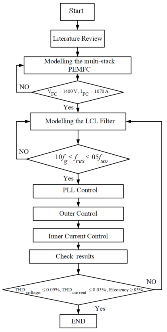
3. Research Method
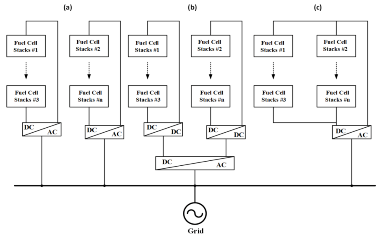
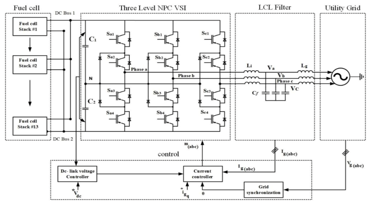
3.1. System Description
3.2. System Modelling
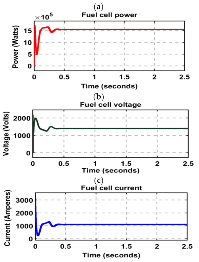
3.2.1. Modelling the Multi-Stack Fuel Cell
- Fuel cell voltage
- 2.
- Nernst voltage
- 3.
- Activation loss
- 4.
- Concentration voltage
- 5.
- Ohmic loss
3.2.2. Designing the Three-Level Neutral Point Clamped Inverter
3.2.3. Modelling the LCL Filter
- Filter capacitor
- 2.
- Current ripple
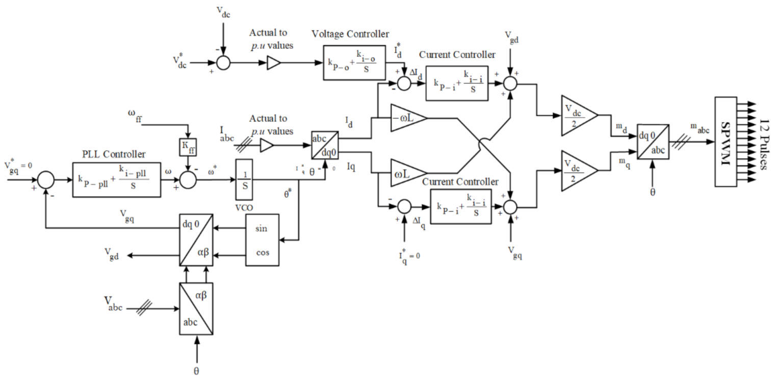
3.2.4. Modelling the Inverter Controller
4. Results
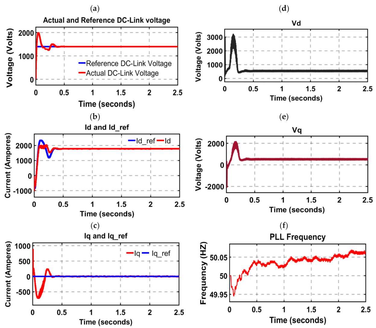
4.1. Control
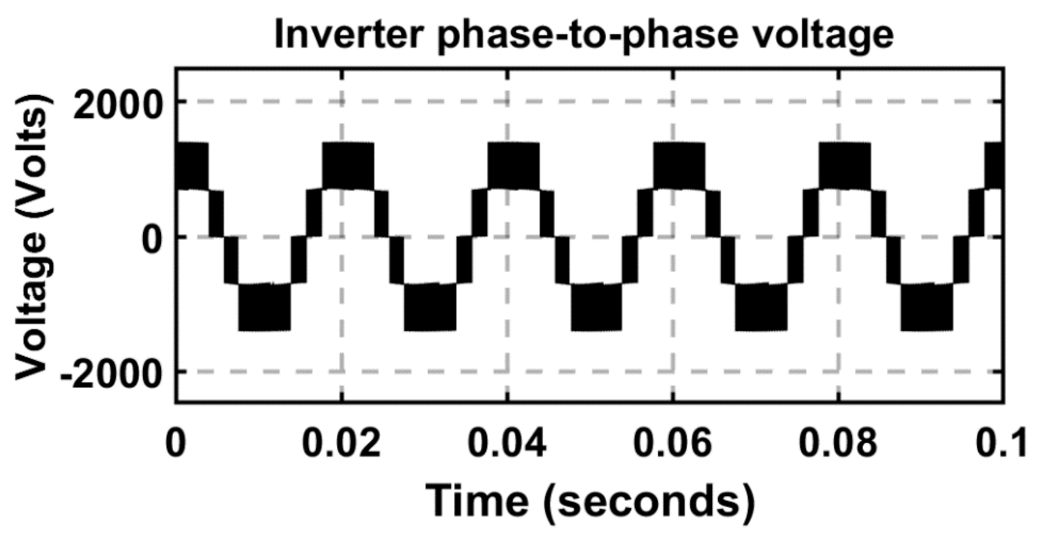
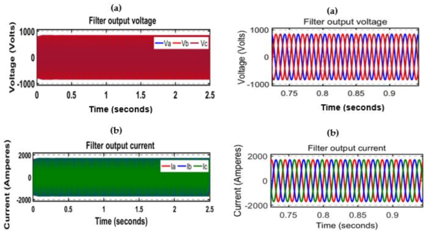
4.2. Inverter Characteristics
5. Case Studies
5.1. Case Study 1
5.2. Case Study 2
6. Discussion
7. Conclusions
Author Contributions
Funding
Institutional Review Board Statement
Informed Consent Statement
Data Availability Statement
Conflicts of Interest
References
- Behrouzi, F.; Nakisa, M.; Maimun, A.; Ahmed, Y.M. Global Renewable Energy and its potential in Malaysia: A review of Hydrokinetic turbine technology. Renew. Sustain. Energy Rev. 2016, 62, 1270–1281. [Google Scholar] [CrossRef]
- Hossain, S.; Abdalla, A.M.; Jamain, S.N.B.; Zaini, J.H.; Azad, A.K. A review on Proton Conducting Electrolytes for Clean Energy and Intermediate Temperature-Solid Oxide Fuel Cells. Renew. Sustain. Energy Rev. 2017, 79, 750–764. [Google Scholar] [CrossRef]
- Luta, D.N.; Raji, A.K. Fuzzy rule-based and particle swarm optimisation MPPT techniques for a fuel cell stack. Energies 2019, 12, 936. [Google Scholar] [CrossRef]
- Luta, D.N.; Raji, A.K. Decision-making between a grid extension and a rural renewable off-grid system with hydrogen generation. Int. J. Hydrogen Energy 2018, 43. [Google Scholar] [CrossRef]
- Luta, D.N.; Raji, A.K. Optimal sizing of hybrid fuel cell-supercapacitor storage system for off-grid renewable applications. Energy 2019, 166, 530–540. [Google Scholar] [CrossRef]
- Taner, T.; Naqvi, S.A.H.; Ozkaymak, M. Techno-economic Analysis of a More Efficient Hydrogen Generation System Prototype: A Case Study of PEM Electrolyzer with Cr-C Coated SS304 Bipolar Plates. Fuel Cells 2019, 19, 19–26. [Google Scholar] [CrossRef]
- Majlan, E.H.; Rohendi, D.; Daud, W.R.W.; Husaini, T.; Haque, M.A. Electrode for proton exchange membrane fuel cells: A review. Renew. Sustain. Energy Rev. 2018, 89, 117–134. [Google Scholar] [CrossRef]
- Taner, T. The micro-scale modeling by experimental study in PEM fuel cell. J. Therm. Eng. 2017, 3, 1515–1526. [Google Scholar] [CrossRef]
- Taner, T. Energy and exergy analyze of PEM fuel cell: A case study of modeling and simulations. Energy 2018, 143, 284–294. [Google Scholar] [CrossRef]
- Liu, J.; Su, C.; Wang, C.; Zhu, L.; He, J. Influence of solid oxide fuel cell on power system transient stability. J. Eng. 2019, 2019, 1081–1086. [Google Scholar] [CrossRef]
- Naik, M.V.; Samuel, P. Analysis of Ripple Current, Power Losses and High Efficiency of DC-DC Converters for Fuel Cell Power Generating Systems. Renew. Sustain. Energy Rev. 2016, 59, 1080–1088. [Google Scholar] [CrossRef]
- İnci, M.; Türksoy, Ö. Review of fuel cells to grid interface: Configurations, technical challenges and trends. J. Clean. Prod. 2019, 213, 1353–1370. [Google Scholar] [CrossRef]
- Marx, N.; Boulon, L.; Gustin, F.; Hissel, D.; Agbossou, K. A review of Multi-stack and Modular Fuel Cell Systems: Interests, Application Areas and on-Going Research Activities. Int. J. Hydrogen Energy 2014, 39, 12101–12111. [Google Scholar] [CrossRef]
- Yu, X.; Starke, M.; Tolbert, L.; Ozpineci, B. Fuel Cell Power Conditioning for Electric Power Applications: A summary. IET Electr. Power Appl. 2007, 1, 643–656. [Google Scholar] [CrossRef]
- Hudson, R.M.; Behnke, M.R.; West, R.; Gonzalez, S.; Ginn, J. Design considerations for three-phase grid connected photovoltaic inverters. In Proceedings of the Record of the IEEE Photovoltaic Specialists Conference, New Orleans, LA, USA, 19–24 May 2002; pp. 1396–1401. [Google Scholar]
- Gao, F.; Li, D.; Loh, P.C.; Tang, Y.; Wang, P. Indirect DC-link voltage control of two-stage single-phase PV inverter. In Proceedings of the IEEE Energy Conversion Congress and Exposition, ECCE 2009, Bologna, Italy, 20–24 September 2009; pp. 1166–1172. [Google Scholar]
- Xiao, W.; Moursi, M.S.E.; Khan, O.; Infield, D. Review of grid-tied converter topologies used in photovoltaic systems. IET Renew. Power Gener. 2016, 10, 1543–1551. [Google Scholar] [CrossRef]
- Massawe, H.B. Grid Connected Photovoltaic Systems with SmartGrid Functionality. Master’s Thesis, Norwergian University of Science and Technology, Trondheim, Norway, 2013. [Google Scholar]
- Mirafzal, B.; Adib, A. On Grid-Interactive Smart Inverters: Features and Advancements. IEEE Access 2020, 8, 160526–160536. [Google Scholar] [CrossRef]
- Koutroulis, E.; Blaabjerg, F. Methodology for the optimal design of transformerless grid-connected PV inverters. IET Power Electron. 2012, 5, 1491–1499. [Google Scholar] [CrossRef]
- Islam, M.; Mekhilef, S. An Improved Transformerless Grid-Connected Photovoltaic Inverter with Reduced Leakage Current. Energy Convers. Manag. 2014, 88, 854–862. [Google Scholar] [CrossRef]
- Çelik, Ö.; Teke, A.; Tan, A. Overview of Micro-Inverters as A challenging Technology in Photovoltaic Applications. Renew. Sustain. Energy Rev. 2018, 82, 3191–3206. [Google Scholar] [CrossRef]
- Mancilla-David, F.; Arancibia, A.; Riganti-Fulginei, F.; Muljadi, E.; Cerroni, M. A maximum power point tracker variable-dc-link three-phase inverter for grid-connected PV panels. In Proceedings of the IEEE PES Innovative Smart Grid Technologies Conference Europe, Berlin, Germany, 14–17 October 2012; pp. 1–7. [Google Scholar]
- Lai, J.S.; Ellis, M.W. Fuel Cell Power Systems and Applications. Proc. IEEE 2017, 105, 2166–2190. [Google Scholar] [CrossRef]
- Rana, R.A.; Patel, S.A.; Muthusamy, A.; Lee, C.W.; Kim, H.J. Review of Multilevel Voltage Source Inverter Topologies and Analysis of Harmonics Distortions in FC-MLI. Electronics 2019, 8, 1329. [Google Scholar] [CrossRef]
- Hamad, K.B.; Kahn, M. TE Modelling and Control of a grid-tied Power Conditioning Unit for a Megawatt Fuel Cell System. Int. J. Eng. Technol. 2019, 9, 149–163. [Google Scholar] [CrossRef]
- Silaa, M.Y.; Derbeli, M.; Barambones, O.; Cheknane, A. Design and Implementation of High Order Sliding Mode Control for PEMFC Power System. Energies 2020, 13, 4317. [Google Scholar] [CrossRef]
- Ceran, B.; Orłowska, A. The Impact of Power Source Performance Decrease in a PV/WT/FC Hybrid Power Generation System on the Result of a multi-Criteria Analysis of Load Distribution. Energies 2019, 12, 3453. [Google Scholar] [CrossRef]
- Do, T.C.; Truong, H.V.A.; Dao, H.V.; Ho, C.M.; To, X.D.; Dang, T.D.; Ahn, K.K. Energy management strategy of a PEM fuel cell excavator with a supercapacitor/battery hybrid power source. Energies 2019, 12, 4362. [Google Scholar] [CrossRef]
- Bizon, N.; Raceanu, M.; Koudoumas, E.; Marinoiu, A.; Karapidakis, E.; Carcadea, E. Renewable/Fuel Cell Hybrid Power System Operation Using Two Search Controllers of the Optimal Power Needed on the DC Bus. Energies 2020, 13, 6111. [Google Scholar] [CrossRef]
- Spasova, B.; Kawamoto, D.; Takefuji, Y. A study of fuel cell scheduling effect on local energy markets with heterogeneous renewable sources. Energies 2019, 12, 854. [Google Scholar] [CrossRef]
- Zhang, Y.; Shi, J.; Fu, C.; Zhang, W.; Wang, P.; Li, J.; Sumner, M. An enhanced hybrid switching-frequency modulation strategy for fuel cell vehicle three-level DC-DC converters with quasi-Z source. Energies 2018, 11, 1026. [Google Scholar] [CrossRef]
- Sukumar, S.; Marsadek, M.; Ramasamy, A.; Mokhlis, H.; Mekhilef, S. A Fuzzy-Based PI Controller for Power Management of a Grid-Connected PV-SOFC Hybrid System. Energies 2017, 10, 1720. [Google Scholar] [CrossRef]
- Khan, I.; Zeb, K.; Din, W.U.; Islam, S.U.; Ishfaq, M.; Hussain, S.; Kim, H.J. Dynamic modeling and robust controllers design for doubly fed induction generator-based wind turbines under unbalanced grid fault conditions. Energies 2019, 12, 454. [Google Scholar] [CrossRef]
- Hakimi, S.M.; Hajizadeh, A. Integration of Photovoltaic Power Units to Power Distribution System through Modular Multilevel Converter. Energies 2018, 11, 2753. [Google Scholar] [CrossRef]
- Tareen, W.U.K.; Aamir, M.; Mekhilef, S.; Nakaoka, M.; Seyedmahmoudian, M.; Horan, B.; Memon, M.A.; Baig, N.A. Mitigation of power quality issues due to high penetration of renewable energy sources in electric grid systems using three-phase APF/STATCOM technologies: A review. Energies 2018, 11, 1491. [Google Scholar] [CrossRef]
- Das Gupta, T.; Kumar, D.; Chaudhary, K. Modelling and analysis of grid-tied fuel cell system with synchronous reference frame control. In Proceedings of the 4th International Conference on Power, Control and Embedded Systems (ICPCES), Allahabad, India, 9–11 March 2017; pp. 1–6. [Google Scholar]
- Rizqiawan, A.; Hadi, P.; Fujita, G. Development of grid-connected inverter experiment modules for microgrid learning. Energies 2019, 12, 476. [Google Scholar] [CrossRef]
- Jeong, H.G.; Lee, K.B.; Choi, S.; Choi, W. Performance Improvement of LCL Filter-based Grid-Connected Inverters Using PQR Power Transformation. IEEE Trans. Power Electron. 2010, 25, 1320–1330. [Google Scholar] [CrossRef]
- Bao, C.; Ruan, X.; Wang, X.; Li, W.; Pan, D.; Weng, K. Step-by-Step Controller Design for LCL-Type Grid-Connected Inverter with Capacitor–Current-Feedback Active-Damping. IEEE Trans. Power Electron. 2013, 29, 1239–1253. [Google Scholar] [CrossRef]
- Dhar, S.; Dash, P. Adaptive backstepping sliding mode control of a grid interactive PV-VSC system with LCL filter. Sustain. Energy Grids Netw. 2016, 6, 109–124. [Google Scholar] [CrossRef]
- Hamoud, F.; Doumbia, M.L.; Cheriti, A. Power factor improvement in WECS using cascade PI control of passive damping LCL-filter. In Proceedings of the 2015 International Conference on Sustainable Mobility Applications, Renewables and Technology, Kuwait, UAE, 23–25 November 2015. [Google Scholar] [CrossRef]
- Yao, W.; Yang, Y.; Zhang, X. Design and Analysis of Robust Active Damping for LCL Filters Using Digital Notch Filters. IEEE Trans. Power Electron. 2017, 32, 2360–2375. [Google Scholar] [CrossRef]
- Sahoo, H.K.; Subudhi, U. Power System Harmonics Estimation Using Adaptive Filters. In Compendium of New Techniques in Harmonic Analysis; Intech Open Access: London, UK, 2016. [Google Scholar]
- Colak, I.; Kabalci, E.; Bayindir, R. Review of multilevel voltage source inverter topologies and control schemes. Energy Convers. Manag. 2011, 52, 1114–1128. [Google Scholar] [CrossRef]
- Hamad, K.B.; Kahn, M.T. Modeling of a Solid Oxide Fuel Cell Microgrid System for a Megawatt Load. In Proceedings of the 2019 AIUE 17th Industrial and Commercial Use of Energy, Cape Town, South Africa, 25–26 November 2019; SSRN: Cape Town, South Africa, 2019. [Google Scholar]
- Zhang, J.; Yuan, X.; Yan, B.; Zhe, C.; Yong, M.; Xu, L. Generalized load modeling with solid oxide fuel cell (SOFC) considered. In Proceedings of the 2014 International Conference on Power System Technology, Chengdu, China, 20–22 October 2014; pp. 1040–1046. [Google Scholar] [CrossRef]
- Lakshmi, T.V.V.S.; Geethanjali, P.; Krishna Prasad, S. Mathematical modelling of solid oxide fuel cell using Matlab/Simulink. In Proceedings of the International Conference on Microelectronics, Communications and Renewable Energy, Kanjirapally, India, 4–6 June 2013; pp. 1–5. [Google Scholar]
- Ben Hamad, K. Fuel Cell Power Conditioning Multiphase Converter for 1400 V DC Megawatts Stacks. Ph.D. Thesis, Cape Peninsula University of Technology, Cape Town, South Africa, 2019. [Google Scholar]
- Lee, K.-B.; Lee, J.-S. Reliability Improvement Technology for Power Converters; Springer: Singapore, 2017; ISBN 9789811049910. [Google Scholar]
- Chaturvedi, P.; Jain, S.; Agrawal, P. Modeling, simulation and analysis of three-level neutral point clamped inverter using Matlab/Simulink/power system blockset. In Proceedings of the Eighth International Conference, Nanjing, China, 27–29 September 2005; Volume 2. [Google Scholar] [CrossRef]
- Tarasantisuk, C.; Suyata, T.; Tarateeraseth, V.; Witheephanich, K. Active and Reactive Power Control for Three-Phase Grid Inverters with Proportional Resonant Control Strategies. In Proceedings of the 2016 13th International Conference on Electrical Engineering/Electronics, Computer, Telecommunications and Information Technology (ECTI-CON), Chiang Mai, Thailand, 28 June–1 July 2016; pp. 1–6. [Google Scholar]
- Mahlooji, M.H.; Mohammadi, H.R.; Rahimi, M. A review on modeling and control of grid-connected photovoltaic inverters with LCL filter. Renew. Sustain. Energy Rev. 2018, 81, 563–578. [Google Scholar] [CrossRef]
- Reznik, A.; Simoes, M.G.; Al-Durra, A.; Muyeen, S.M. LCL Filter design and performance analysis for grid-interconnected systems. IEEE Trans. Ind. Appl. 2014, 50, 1225–1232. [Google Scholar] [CrossRef]
- Ruau, X.; Wang, X.; Pan, D.; Yang, D.; Li, W.; Bao, C. Control Techniques for LCL-Type Grid-Connected Inverters; Springer: Berlin/Heidelberg, Germany, 2018. [Google Scholar]
- Bayoumi, E.H. Three-phase LCL-Filter for Grid-Connected Inverter Using Cooperative Three-phase LCL-filter for Grid-connected Inverter Using Cooperative Bacteria Foraging Optimization. Wseas Trans. Syst. Control. 2015, 10, 493–502. [Google Scholar]
- Sen, S.; Yenduri, K.; Sensarma, P. Step-by-step Design and Control of LCL filter based Three Phase Grid-connected Inverter. In Proceedings of the 2014 IEEE International Conference on Industrial Technology (ICIT), Busan, Korea, 26 Feburary–1 March 2014; pp. 503–508. [Google Scholar]
- Teodorescu, R.; Liserre, M.; Rodriguez, P. Grid Converters for Photovoltaic and Wind Power Systems; WILEY: New Delhi, India, 2011; ISBN 9780470057513. [Google Scholar]
- Benzazah, C.; Lazrak, L.; Ait, M. Design and Performance Analysis of Energy Conversion Chain, from Multilevel Inverter until the Grid. In Proceedings of the 27th International Conference on Microelectronics, Casablanca, Morocco, 20–23 December 2015; pp. 311–314. [Google Scholar]
- Esmaeilian, H.R.; Fadaeinedjad, R.; Moschopoulos, G. Dynamic operation and Control of a Stand-Alone PEM Fuel Cell System. In Proceedings of the Conference Proceedings-IEEE Applied Power Electronics Conference and Exposition-APEC, Fort Worth, TX, USA, 16–20 March 2014; pp. 3378–3384. [Google Scholar]
- Zhong, Q.-C.; Hornik, T. Control of Power Inverters in Renewable Energy and Smart Grid Integration; WILEY: Hoboken, NJ, USA, 2013; ISBN 9780470667095. [Google Scholar]
- Ali, Z.; Christo, N.; Hadjidemetriou, L.; Kyriakides, E.; Yang, Y. Three-phase phase-locked loop synchronization algorithms for grid-connected renewable energy systems: A review. Renew. Sustain. Energy Rev. 2018, 90, 434–452. [Google Scholar] [CrossRef]
- Timbus, A.; Teodorescu, R.; Blaabjerg, F.; Liserre, M. Synchronization Methods for Three Phase Distributed Power Generation Systems. An Overview and Evaluation. In Proceedings of the IEEE 36th Power Electronics Specialists Conference, Recife, Brazil, 12–16 June 2005. [Google Scholar]
- Merai, M.; Naouar, M.W.; Belkhodja, I.S. An Improved DC-Link Voltage Control Strategy for Grid-Connected Converters. IEEE Trans. Power Electron. 2018, 33, 3575–3582. [Google Scholar] [CrossRef]
- Wong, M.-C.; Dai, N.-Y.; Lam, C.-S. Parallel Power Electronics Filters in Three-Phase Four-Wire Systems; Springer: Berlin/Heidelberg, Germany, 2016; ISBN 9789811015298. [Google Scholar]
- Elbaset, A.A.; Hassan, M.S.; Ali, H. Performance Analysis of Grid-Connected PV System. In Proceedings of the Eighteenth International Middle East Power Systems Conference, Cairo, Egypt, 27–29 December 2016. [Google Scholar]
- Nourdine, A.A.; Yacine, A.A.; Aissa, K.; Brahim, M. Comprehensive Modeling and Simulation of grid-tied PV system. In Proceedings of the 2017 5th International Conference on Electrical Engineering-Boumerdes, ICEE-B 2017, Boumerdes, Algeria, 29–31 October 2017. [Google Scholar]
- Kim, Y.; Cha, H.; Song, B.M.; Lee, K.Y. Design and Control of a Grid-Connected Three-phase 3-Level NPC Inverter for Building Integrated Photovoltaic Systems. In Proceedings of the IEEE PES Innovative Smart Grid Technologies, Washington, DC, USA, 16–20 January 2012. [Google Scholar]
- Novak, M.; Šunde, V.; Jakopović, Ž. Model of three-level neutral point clamped converter (NPC) for grid-connected photovoltaic systems. In Proceedings of the 2015 38th International Convention on Information and Communication Technology, Electronics and Microelectronics (MIPRO), Opatija, Croatia, 25–29 May 2015; pp. 25–29. [Google Scholar]
- Arulkumar, K.; Vijayakumar, D.; Palanisamy, K. Modeling and control strategy of three phase neutral point clamped multilevel PV inverter connected to the grid. J. Build. Eng. 2015, 3, 195–202. [Google Scholar] [CrossRef]
- Ramteke, R.G.; Patil, U.V. Design of Third-order LCL Filter for Diode-Clamped Multi-Level Inverter. In Proceedings of the International Conference on Circuits, Power and Computing Technologies, Nagercoil, India, 20–21 March 2014; pp. 334–338. [Google Scholar]


| Parameter | Value |
|---|---|
| 1.18 V | |
| 1273° K | |
| 973° K | |
| 8.314 kJ/kmol·°K | |
| 98,486 C/mol | |
| 2.13 atm | |
| 2.11 atm | |
| 36.12 atm | |
| 0.3 | |
| 0.5 A | |
| 1000 A | |
| 0.2 Ω | |
| −2870 | |
| 0.126 Ω | |
| 300 A |
| Parameter | Value |
|---|---|
| Nominal power per stack | 126,000 W |
| Maximum power per stack | 134,400 W |
| Nominal operating current | 90 A |
| Stack open-circuit voltage | 2000 V |
| Stack nominal voltage | 1400 V |
| Resistance per stack | 8.2936 |
| Number of cells per stack | 2000 |
| Stack efficiency | 55% |
| Number of stacks | 12 |
| Multi-stack open-circuit voltage | 2000 V |
| Multi-stack nominal power | 1.54 MW |
| Multi-stack nominal current | 1070 A |
| Multi-stack nominal voltage | 1400 V |
| Switching State | State of the Switching Device | Output Voltage Vxz (x = a, b, c) | |||
|---|---|---|---|---|---|
| Sa1 | Sa2 | Sa3 | Sa4 | ||
| P | ON | ON | OFF | OFF | Vdc/2 |
| O | OFF | ON | ON | OFF | 0 |
| N | OFF | OFF | ON | ON | −Vdc/2 |
| Parameters | Value |
|---|---|
| DC power | 1.54 MW |
| DC-Link Voltage | 1400 V |
| Active power | 1.2 MW |
| Line voltage after filter | 600 V |
| Current after filter | 1200 A |
| Power factor | 0.85 |
| PWM carrier frequency | 2000 Hz |
| Grid frequency | 50 Hz |
| Modulation range | 0.7 |
| Attenuation factor | 20% |
| Acceptable maximal power factor variation | 5% |
| Inverter configuration | Three-phase |
| Parameter | Value |
|---|---|
| Inverter side inductor (Li) | 0.9 mH |
| Grid side inductor (Lg) | 0.072 mH |
| Capacitor filter (Cf) | 531 µF |
| Damping Resistor (Rd) | 0.118 Ω |
| Resonant frequency (fres) | 845 Hz |
| Inductors resistances (Ri = Rg) | 0.00761Ω |
| Sampling frequency (fs) | 10,000 Hz |
| Crossover frequency (fc) | 254 Hz |
| Parameter | Value |
|---|---|
| 5000 µF | |
| 133.5 | |
| 303,409.1 | |
| 3.24 | |
| 50.625 | |
| 9.7 | |
| 22,045.45 |
| [59] | [66] | [67] | [68] | [69] | [70] | [71] | This Study | ||
|---|---|---|---|---|---|---|---|---|---|
| Source type | Renewable energy | PV | PV | PV | PV | PV | Renewable energy | PEMFC | |
| PCU type | DC/AC | DC/DC DC/AC | DC/AC | DC/DC DC/AC | DC/DC DC/AC | DC/DC DC/AC | DC/AC | DC/AC | |
| Multilevel inverter | 3-Level NPC | 3-Level NPC | 3-Level NPC | 3-Level NPC | 3-Level NPC | 3-Level NPC | 5-Level NPC | 3-Level NPC | |
| Filter type | LCL | LC | LCL | LC | LCL | LCL | LCL | LCL | |
| Topology | Grid-tied | Grid-tied | Grid-tied | Grid-tied | Grid-tied | Grid-tied | Grid-tied | Grid-tied | |
| DC Voltage | 2200 V | 500 V | - | 350–850 V | 1000 V | 800 V | 400 V | 1400 V | |
| AC Voltage | 1380 V | - | - | 380 V | 400V | 325 V | 283 V | 600 V | |
| DC power | - | 100 kW | - | - | 200 kW | 9.5 kW | - | 1.5 MW | |
| AC Power | 7 MVA | - | - | 13 kW | 160 kW | - | 5 kW | 1.3 MW | |
| Switching Frequency | 2 kHz | 5 kHz | - | 5 kHz | 8 kHz | 5 kHz | 10 kHz | 2 kHz | |
| Efficiency | - | - | 88% | 97.5% | 80% | - | - | 88% | |
| Number of Standards | IEEE Std 519-1992 | - | IEC61727, IEEE1547 | - | - | - | IEEE 519-1992 | IEEE 519-2014 | |
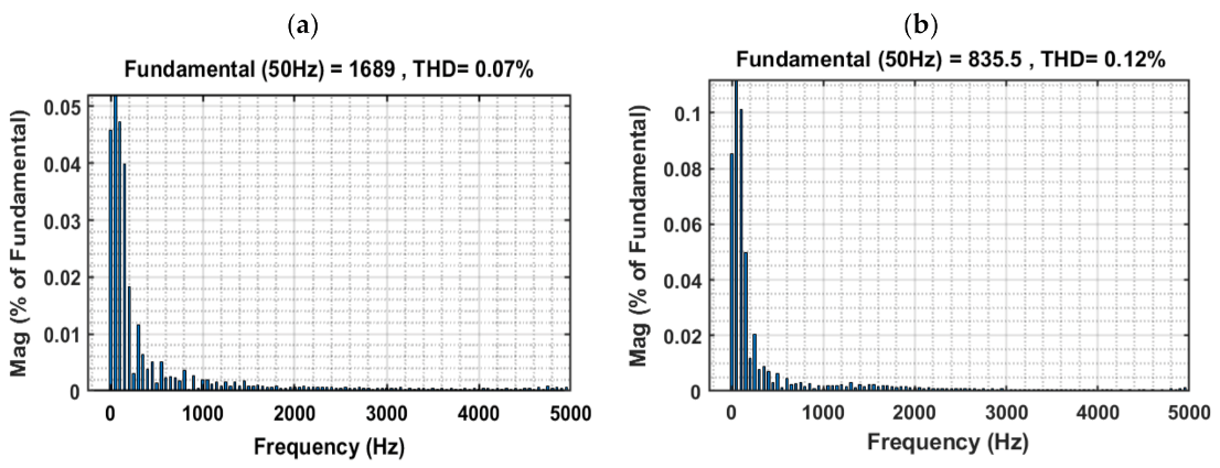
| THD of Voltage | 2.44% | 1.01% | 1.27% | - | - | 3% | 0.33% | 0.12% | |
| THD of Current | 0.16% | - | 2.41% | <3% | 0.72% | - | - | 0.07% | |
Publisher’s Note: MDPI stays neutral with regard to jurisdictional claims in published maps and institutional affiliations. |
© 2021 by the authors. Licensee MDPI, Basel, Switzerland. This article is an open access article distributed under the terms and conditions of the Creative Commons Attribution (CC BY) license (http://creativecommons.org/licenses/by/4.0/).
Share and Cite
Ben Hamad, K.; Luta, D.N.; Raji, A.K. A Grid-Tied Fuel Cell Multilevel Inverter with Low Harmonic Distortions. Energies 2021, 14, 688. https://doi.org/10.3390/en14030688
Ben Hamad K, Luta DN, Raji AK. A Grid-Tied Fuel Cell Multilevel Inverter with Low Harmonic Distortions. Energies. 2021; 14(3):688. https://doi.org/10.3390/en14030688
Chicago/Turabian StyleBen Hamad, Khlid, Doudou N. Luta, and Atanda K. Raji. 2021. "A Grid-Tied Fuel Cell Multilevel Inverter with Low Harmonic Distortions" Energies 14, no. 3: 688. https://doi.org/10.3390/en14030688
APA StyleBen Hamad, K., Luta, D. N., & Raji, A. K. (2021). A Grid-Tied Fuel Cell Multilevel Inverter with Low Harmonic Distortions. Energies, 14(3), 688. https://doi.org/10.3390/en14030688