Article

Efficiency Enhancement on Hybrid Power System Composed of Irreversible Solid Oxide Fuel Cell and Stirling Engine by Finite Time Thermodynamics

Department of Mechanical Engineering, National Cheng Kung University, Tainan 701, Taiwan
*
Author to whom correspondence should be addressed.
Energies 2021, 14(4), 1037; https://doi.org/10.3390/en14041037
Submission received: 6 January 2021 / Revised: 7 February 2021 / Accepted: 12 February 2021 / Published: 16 February 2021
(This article belongs to the Special Issue Advances in Hydrogen and Fuel Cell Systems)

Abstract

:
This paper presents the work for efficiency enhancement on a hybrid power system with an irreversible Solid Oxide Fuel Cell (SOFC) and Stirling Engine (SE) for various system design using the approach of finite-time thermodynamics. The SOFC-based cogeneration system was integrated with an SE and several heat components. The effects of design configurations using various interface components on system performance were investigated. By analyzing the SE with finite-time thermodynamics and considering multiple irreversible factors of output power given by the SOFC, the efficiency of the calculation can be more practical and accurate. In this study, the working efficiency of the proposed hybrid system was enhanced by 16.37% compared to that of the conventional system at an intermediate temperature of 873 K. The design approach proposed herein is considered an essential package for building highly efficient power systems working in the intermediate temperature range.

1. Introduction

The Solid Oxide Fuel Cell (SOFC) offers high efficiency and low-pollution technology to generate electric power. The SOFC system also provides many advantages in the energy conversion processes, including high fuel utilization, high reliability, and high fuel adaptability [1,2]. Based on the fact that the exhaust gas of the SOFC system is usually of high temperature, the system can then be used to combine with different engines to construct a hybrid system for better electric power output and system efficiency. Several earlier studies in this area have investigated the hybrid SOFC system by combining various kinds of engines to increase system efficiency. For example, in earlier work, the SOFC was combined with a gas turbine (GT) [3] to utilize the exhaust gas, which includes nitrogen, oxygen, carbon dioxide, carbon monoxide, and vapor when using hydrocarbon fuel for the SOFC system, into GT in power generation processes. By utilizing the exhausted high-temperature gas, the efficiency of both the thermal energy and power generation for the hybrid system was enhanced.
Mitsubishi Heavy Industries [4] has built a 200 kW SOFC hybrid system by combining tube-type SOFC and micro gas turbine (MGT), and it started to combined the SOFC and steam turbine (ST) for an 800 MW gas turbine combine cycle (GTCC). On the other hand, scientists also used different thermal cycles, such as the Rankine cycle, Carnot cycle, Stirling cycle, and Brayton cycle, to combine with a SOFC and they simulated the performance of power with different operation conditions [5,6,7,8]. Based on the data given in the literature, it is clear that the efficiency of power generation can be enhanced up to 70% by using various proposed hybrid systems.
Based on the facts presented above, different thermal cycles combined with SOFC are possible to enhance the overall efficiency of the hybrid system. The Stirling Engine (SE) is one of the thermal cycles commonly used in the past since it possesses the same thermal efficiency as the Carnot cycle with many other advantages such as low gas and noise pollution. Since SE is an external combustion engine, it means that SE can be utilized to combine with different power generation systems including solar and fuel cells. Thus, it can be selected a suitable device to fully utilize the exhaust gas from the power generation system [9,10,11,12,13,14,15]. Sanchez, et al. [8] in 2009 showed that by combining the Molten Carbonate Fuel Cell (MCFC) with SE, the hybrid system exhibited a greater potential of power generation than that of Rankine cycles and Brayton cycles.
Although the hybrid SOFC-SE system has been studied infrequently by experimentalists, the system’s efficiency and the performance of both SOFC and SE often needs to be calculated carefully before building an experiment. Therefore, most studies in the literature commonly use the Carnot cycle efficiency to analyze the efficiency of the Stirling cycle to obtain maximum possible efficiency [16]. Using the Carnot cycle efficiency method to evaluate the efficiency of the Stirling cycle is not a suitable way to obtain maximum efficiency for SE. However, the method of using the Carnot cycle does not consider the differences in temperatures between the heat source and process flows. Based upon the discussion above, it becomes obvious that the efficiency of the Stirling cycle estimated by Carnot cycle efficiency cannot match the data obtained directly from real-world experiments.
Carnot efficiency is invariably far above the efficiency of real heat engines and hence is of very limited practical value, because of the reversible conditions under which heat engines would have to operate to achieve Carnot efficiency corresponding to zero power output. This has led to the advent of a new field which is called finite-time thermodynamics. Novikov [17], Chambada [18], and Curzon et al. [19] used finite-time thermodynamics to consider finite-time heat transfer and calculated the heat loss between the heat source and process flows. However, the Carnot cycle is an internal combustion engine, which is not suitable when using SOFC’s exhaust gas to generating power. Therefore, the Stirling engine would be an ideal engine for this research to integrate with SOFC for a hybrid system. In addition to the above studies, some scholars have applied this method to system computing, including SOFC systems.
To study the irreversible hybrid system for SOFC-SE, Emin [20] used finite time thermodynamics to analyze the performance of SE. However, the system that Emin [20] has analyzed is a system that has been simplified, especially the heating process for fuel and air. To evaluate the performance of SOFC-SE in detail, finite-time thermodynamics and SOFC irreversibility would be used to calculate the power generation and efficiency with a different system design. In addition, the embryonic form of SOFC-SE system design can be referred to in the literature [21], which considers heat exchanger and burner to make the heat process of the system more thorough.
Based on the literature, system analysis plays an important role in the study of the SOFC power system. However, most of the previous work has concentrated on the system from the viewpoint of thermodynamic balance, which ignored the heat loss in simulation processes. Although some research has evaluated the system by finite-time thermodynamics to consider the heat loss, the model being employed was not quite sufficient. In this paper, the finite-time thermodynamics will be used to analyze the hybrid system of SOFC-SE with complete system efficiency. Several different system design configurations will be used to estimate the power generation in the present work to facilitate a more realistic result of simulation for the hybrid SOFC-SE system. The aim is to improve system efficiency estimation with feasible new design configurations.

2. Modeling and Methods

2.1. Irreversibility of SOFC in Power Generation

To calculate the maximum generated power output of SOFC, the voltage of the fuel cell is composed of irreversible elements, such as activation polarization, concentration polarization, ohmic polarization, and thermal irreversibility which would not be considered in the ideal model [22]. Therefore, the research in this paper would start to consider the irreversibility of heat transfer in the SOFC stack, where the equation of voltage can be estimated as:
U = E - U a c t U c o n U o h m U t h e r m a l
where U a c t is the voltage loss of activation polarization, U c o n is the voltage loss of concentration polarization, U o h m is the voltage loss of ohmic polarization and U t h e r m a l is the voltage loss of the irreversibility by heat transfer during the chemical reaction, and E is the ideal voltage for SOFC, that can be estimated as:
E = Δ g ( T ) n e F + R T n e F ln [ P H 2 P O 2 P H 2 O ]
where Δ g ( T ) is Gibbs energy, R is the ideal gas constant, and P H 2 , P O 2 and P H 2 O are partial pressure of hydrogen, oxygen, and water, respectively, for the chemical reaction in the SOFC. n e is the number of electrons transferred in the reaction, n e F is Faraday’s constant, T is the working temperature of the SOFC cell.
To analyze the irreversibility of SOFC in the reactive processes, the polarization of ohmic, activation, and concentration should be included. The activation polarization Uact is the potential difference above the equilibrium value required to produce a current that depends on the activation energy of the redox event, which can be estimated as:
U a c t = 2 R T F [ sinh 1 ( i 2 i 0 , a ) + sinh 1 ( i 2 i 0 , c ) ]
where i 0 , a and i 0 , c are the exchange current density of the anode and cathode, respectively. Exchange current density in electrochemical reactions is analogous to the rate constant in chemical reactions. That indicates a higher exchanger current density can facilitate a better performance of the cell. Whereas concentration polarization, induced by the concentration gradient of the reactants and the products in the bulk electrolyte, as well as on the electrode surface, can be estimated in terms of slow mass transport in cell reactions by the equation:
U c o n = - R T n e F [ ln ( 1 - i i L , a ) + ln ( 1 - i i L , c ) ]
where i L , a and i L , c are limiting current density of the anode and cathode, respectively. The ohmic polarization, induced by the presence of electrical resistance in cell components, can be estimated by:
U o h m = i L e l T σ 0 exp ( E e l R T )
where E e l is the activation energy of ion conductivity, L e l is the thickness of electrolyte, and σ 0 is the ion conductivity. When considering non-equilibrium thermodynamics and finite-time thermodynamics, the heat transfer between the cell and environment will have to be characterized. Thus, the irreversibility of heat transfer should be estimated by the polarization [23] of the equation given as:
U t h e r m a l = Δ g n e F ( 1 T 1 T 0 )
Based on the derivation given above, the SOFC performance and efficiency can now be put together and expressed as:
η F C = P F C - Δ H λ = P F C - λ ( i A / n e F ) Δ h = n e U F Δ h λ
P F C = λ U i A
where Δ H is the enthalpy change in the electrochemical reaction, F is the Faraday constant, n e is the number of charges, Δ h is the molar enthalpy change of SOFC, i is the current density, A is the reactive area, U is the output voltage of SOFC, and λ is the fuel utilization.

2.2. Power Generation and Efficiency of the Stirling Engine Using Finite-Time Thermodynamics

The Stirling cycle consists of two isothermal branches and two constant generalized coordinate branches, i.e., constant-volume or isomagnetic branches, and the P-V diagrams are shown in Figure 1. To consider the heat transfer process with the finite-time thermodynamics method, the heat transfer between the heat source and heat sink can be rewritten as:
Q 1 = θ ( T H - T 1 ) t 1
Q 1 = n R T 1 ln x
Q 2 = θ ( T 2 - T L ) t 2
Q 2 = n R T 2 ln x
where θ is the heat transfer coefficient between working fluids and the heat sink, T H and T L are the high/low temperature of the heat sink, T 1 and T 2 are the temperatures of working fluids, n is the molar number of working fluids, x is the compression ratio, t 1 and t 2 are the time of isothermal compress and expand processes. To consider the heat loss in the regenerative heat process [11], the heat loss can be estimated by the equation:
Δ Q = α n C ( T 1 T 2 )
where C is the heat capacity of the working substance per mole partaking in the regenerative branches and α is the fractional deviation from ideal regeneration. Therefore, the heat transfer between working fluids and the heat source can be expressed as:
Q H = Q 1 + Δ Q
Q L = Q 2 + Δ Q
To simplify the computational process, the time spent on the regenerative branches is assumed to be proportional to that of the isothermal branches, given as:
t r e = b ( t 1 + t 2 )
where b is a constant, and the cyclic period is given as:
t = t r e + t 1 + t 2 = ( 1 + b ) ( t 1 + t 2 )
By plugging Equations (10) and (11) into Equation (15), the cyclic period can be rewritten as:
t = n [ R T 1 ln x + α C ( T 1 T 2 ) ] θ ( T H - T 1 ) + n [ R T 2 ln x + α C ( T 1 T 2 ) ] θ ( T 2 - T L )
Thus, the rate of heat generation can be derived and given as:
Q ˙ H = ln x + α ( 1 y ) ( δ 1 ) ( 1 + b ) ( ln x θ ( T H T 1 ) + y ln x θ ( y T 1 T L ) )
By giving the rate of heat generation, the compression ratio can be calculated and the efficiency can be obtained by:
η s t = 1 Q ˙ L Q ˙ H = ( 1 y ) ( 1 + α ( 1 y ) ln x ( δ 1 ) )
Where δ is the ratio of the specific heats, and the heat output of Stirling engine can be determined by:
Q L . = Q H . ( 1 η s t )
While the power of the Stirling engine can be estimated by:
P s t = Q H . Q L

2.3. Power Generation and Efficiency of Hybrid SOFC-SE System

As given in Figure 2, it can be seen that the hybrid SOFC-SE system, in addition to the SOFC stack and SE, also comprehend some other subsystems including the burner, heater, and heat exchanger. Therefore, the system efficiency will be influenced by these subsystems. When considering the efficiency, the energy transfer among SOFC, SE, and subsystems in system loops should be considered carefully. To estimate the efficiency, the energy of the burner, being transferred from the exhaust fuel gas out of SOFC stack to the heat source for raising the system temperature, can now be given as:
P b u r n e r = i A n e F ( 1 λ ) Δ h
where λ is the utilization of fuel. Although the burner is a heat generation component for the hybrid SOFC-SE, the heat is not enough to supply all components in the whole process. Therefore, the heater is introduced to play the role of such an energy supply. The heat supplied by the heater toward the SOFC stack can be estimated as:
P 1 = - Δ H P F C + Q a d d × ε h
where Q a d d is the amount of heat supplied by the heater, and ε h is the efficiency of the heater. The heat exchanger is the main component to transfer heat from the high-temperature exhaust gas to the low-temperature fuel gas. Therefore, the flow temperature of input to and output from the heat exchanger can be calculated by the equations given below:
T 1 = T + Δ H ( 1 λ ) m a i r C p a i r
where T 1 is the hot source input temperature of the heat exchanger. Based upon the operating characteristics of the SOFC stack, the relationship of stack temperature and the input flow temperature of the SOFC stack can be expressed as:
T 4 = T - Δ T
where T 4 is the input flow temperature for the SOFC stack, and Δ T is the temperature gradient between the stack and input flow.
To calculate the temperature of output and input flow to and from in heat exchanger at the hot side and cold side, the exchanged heat can be estimated as:
m a i r C p a i r ( T 2 T 1 ) × ε e x = m a i r C p a i r ( T 4 T 3 ) + m H 2 C p H 2 ( T 4 T 3 )
where m h 2 and m a i r are the mass of hydrogen and air, C p , H 2 and C p , a i r are the capacity of hydrogen and air, and ε e x is the efficiency of the heat exchange.
Based upon Equations (23)–(25), the temperature T2 of input flow for the Stirling engine can be estimated. However, T2 is influenced by temperature T3 of the input flow of heat exchanger number one (HEX1), which is heated by heat exchanger number two (HEX2). To estimate more realistic temperatures in the SOFC system, an iteration procedure is introduced to estimate the temperatures T2 and T3. Additionally, the mass flow of air is derived and presented as:
m a i r = V a i r i A μ a i r n e F = n a i r × μ a i r
where V a i r and V H 2 are the volume ratios of the air and hydrogen, n a i r and n H 2 are the mole ratios of the air and hydrogen, and μ a i r μ H 2 are the molar mass of the air and hydrogen.
To estimate the power generation of the Stirling engine given in Equations (9)–(20), the exhaust heat of the heat exchanger number one (HEX1) can now be given as:
P 2 = P 1 × ( 1 - ε e x )
As shown in Figure 2, the exhaust flow of SE is used to heat the gas and increase the system efficiency. The temperature between input and output flows of the heat exchanger number two (HEX2) can now be given as:
Q L × ε e x = m a i r C p a i r ( T 3 T 0 ) + m H 2 C p H 2 ( T 3 T 0 )
where Q L is the exhaust energy from the Stirling engine. To calculate system temperature in heat balance state, Equations (25)–(28) will be repeatedly used in the estimation process, and the exhaust heat Q L can finally be obtained by the equation given as:
Q L = Q L × ( 1 - ε e x )
The total power generated for the complete system given in Figure 2 can be given as:
P t o t a l = P F C + P s t
and the efficiency of the overall power generation can be then be calculated by the equation:
η t o t a l = P F C + P s t Δ H + Q a d d

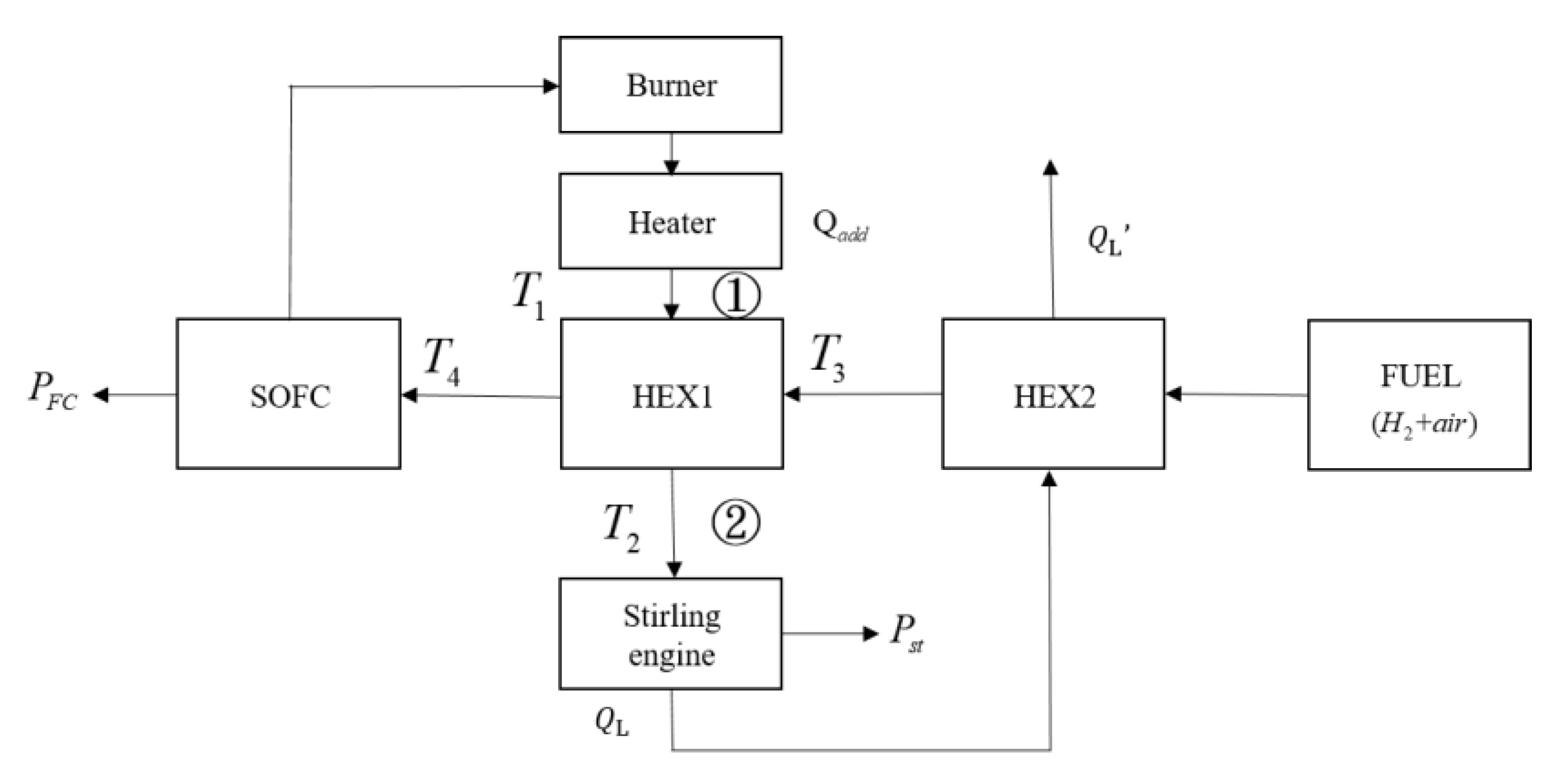
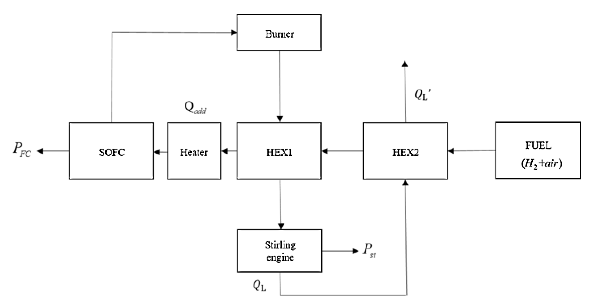
2.4. Operation Parameters and Loops of the Hybrid SOFC-SE

The study aims to estimate and improve upon the efficiency of a hybrid SOFC-SE system using the principle of finite thermodynamics. Here, we adopted the system interfaces given in Emin [20] for easy comparison, and the detailed operation parameters have been shown in Table 1 [24]. Several common components including Regenerator (R), Burner (B), Heater (H), a Heat exchanger (HEX), SOFC, and Stirling engine (SE) are included. In order to estimate the efficiency of the whole power generation system, the following assumptions are made.
  • All system components are operated in a steady state.
  • All gas used in the system is assumed ideal.
  • To estimate temperature differences among various components in the whole system, the input or output temperature of the SOFC stack is assumed constant.
  • The type of cell used is electrolyte-supported, and the materials for the anode, electrolyte, and cathode are Ni-YSZ (Yttria-stabilized zirconia,), YSZ, and LSM (Strontium substituted Lanthanum Manganite).
  • Radiant heat transfer is not considered in this study.
  • All fuel is assumed fully consumed in the burner.

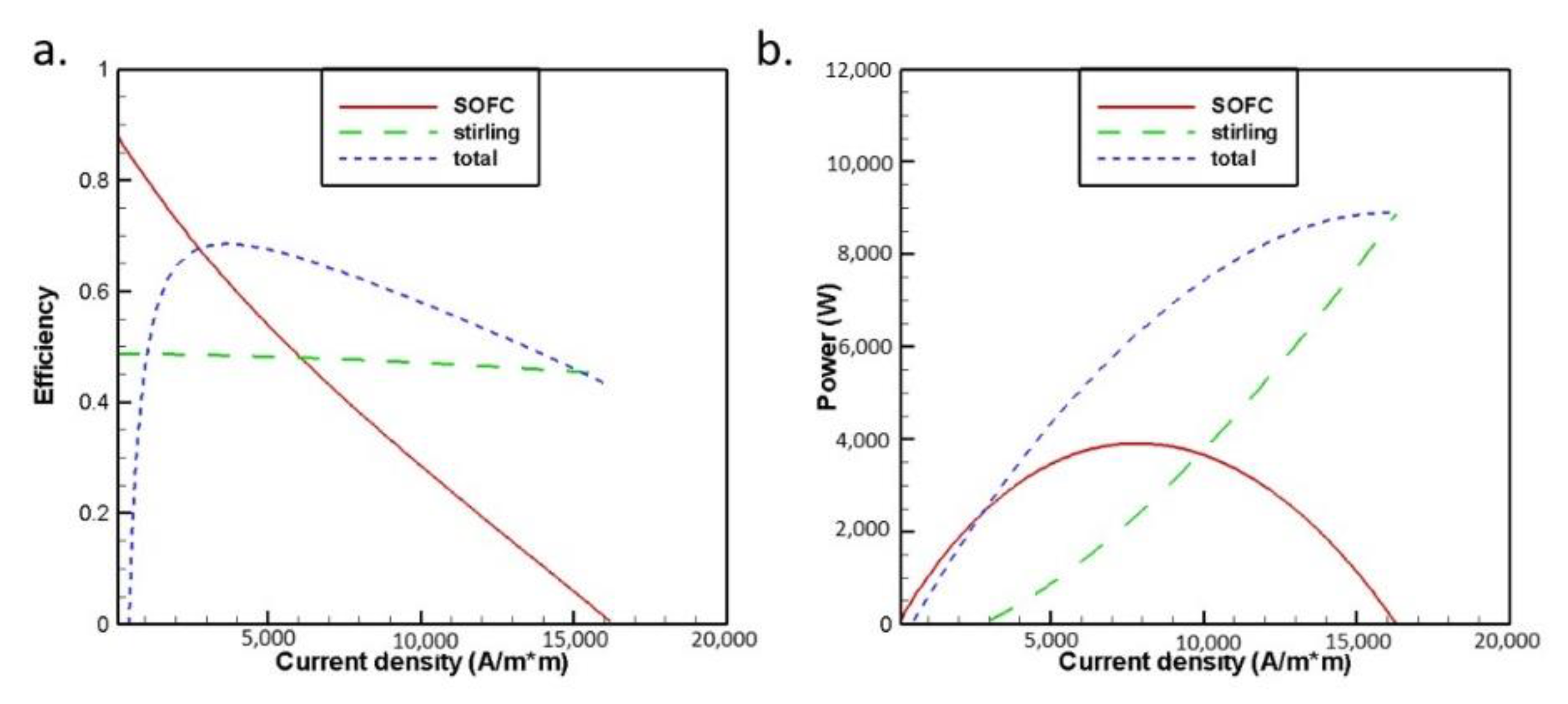
3. Results and Discussion

In order to investigate the efficiency of hybrid SOFC-SE systems with different design configurations, the simulation was carried out in this study using two consecutive steps. First, the employment of different operating conditions to the same system for system operation efficiency evaluation. Second, the employment of different heating components to improve overall system efficiency.
For easy verification of the simulation results, the system loop of Emin [20], which is presented in Figure 3, was used for study, but the whole calculation process was based on Equations (1)–(31). As shown in Figure 4 and Figure 5, the efficiency of the hybrid SOFC-SE system is simulated for two different operating temperatures. As given in Figure 4, the system efficiency is found to be increased when the current density of SOFC is increased from 0 to 3000 (A/ m2). However, the efficiency is decreased as the current density becomes greater than 3000 (A/m2). This is because the system needs more heat energy for increasing power output.
As shown in Figure 4 and Figure 5, we observed that the maximum system efficiency of the hybrid SOFC-SE system is increased up to 68.52% when operated at 873 K, and 62.32%, when operated at 1173 K. Since the hybrid SOFC-SE loop in Figure 3 can be further improved and optimized by employing some effective heat components to replace the generator, we will investigate some new design configuration loops to come up with a more pragmatically efficient and effective hybrid SOFC-SE system. Figure 6 is such a system loop that includes some heating components of the burner, heater, and heat exchanger (HX). As given in Figure 6, by employing some proposed common heating components in the simulation process, the results for system efficiency and power generated of the new hybrid SOFC-SE loop can be characterized and presented. As shown in Figure 7 and Figure 8, the maximum efficiency of the hybrid SOFC-SE system is increased up to 63.41% when operated at 873 K, and 51.41% when operated at 173K. From the simulation results presented above, it becomes clear that using some effective heat components to replace the regenerator in the hybrid SOFC-SE loop can lead to the results of better efficiency and power output.
After modeling the design configuration of the hybrid SOFC-SE given in Figure 6, we find that when the regenerator is replaced using a burner, heater, and heat exchanger, the whole system efficiency will decrease. In other words, the simulation results given in Figure 7 and Figure 8 indicate that lower system efficiency was obtained when systems are operated at both 873 K and 1173 K. Therefore, optimizing the system loop for raising system efficiency using the finite-time thermodynamics method becomes very essential.
Based on the system loop given in Figure 6, we find that the exhaust gas coming out from the burner is reused only by heat exchanger number one (HEX1) and SE. Since the heat is not yet fully utilized, it can be recycled by introducing some heat components into the system. By so doing, more heat can be extracted and supplied to the system as input to maintain the SFOC stack to maintain a higher working temperature environment. In order to decrease the input heat from the heater and increase the recycling rate of the heat inside the SOFC system, increasing the heat exchanger to recycle more exhaust heat and changing the location of the heater to decrease the input heat is an effective approach to increase system efficiency. Figure 9 shows the design of a hybrid SOFC-SE system after system optimization.
The simulation results of the optimized hybrid SOFC-SE system are presented in Figure 10 and Figure 11. It shows that the maximum system efficiency of the optimized hybrid SOFC-SE system is enhanced up to 67.67% when operated at 873 K, and 56.59% when operated at 1173 K. Compared to the efficiency of the two different system design configurations of Figure 5 and Figure 8, we found that employing another heat exchanger to recycle the exhaust heat from the Sterling Engine (SE) can further decrease heat flux and increase the efficiency. However, the efficiency of the SOFC-SE system is decreased by 11.08% when the operating temperature of the SOFC stack is increased from 873 K to 1173 K. The reason why the efficiency of the hybrid SOFC system is decreased for increasing input temperature is because of the input heat Qadd in the heater. Although the power output of the SOFC stack is increased for the increasing stack temperature, the hybrid SOFC system will require more heat to input into the system, and that will directly decrease the system efficiency.
Based upon the simulation results presented above, when a regenerator is used to represent the function of a hotbox it cannot truly characterize the behavior of the heat transfer in the SOFC system. However, by replacing regenerator with heat components and considering design configurations of different components for the hybrid SOFC-SE system, the system heat transfer behavior can be well characterized. The method of finite-time thermodynamics was introduced for simulations since it could be used not only to estimate system efficiency and power generation for various operating conditions of the hybrid SOFC-SE system but also to evaluate the irreversibility of the system. Table 2 shows the simulation results of both system efficiency and power output for two different design configurations. The simulation results indicate that the efficiency of the hybrid SOFC-SE system decreases as operating temperature increases. This is because the hybrid SOFC-SE system usually requires more heat energy to maintain a higher working temperature for SOFC stacks. In other words, the hybrid system needs more heating energy input to generate the power for a higher working temperature.
To further optimize the efficiency of hybrid SOFC-SE systems of various design configurations, we introduced some heat components, such as the burner (B), heater (H), heat exchanger number one (HEX1), and heat exchanger number two (HEX2), to the system to replace the regenerator (R). Based on the simulation results presented in Table 2 and Table 3, it can be found that when the regenerator, as given in Emin [20], is employed, the highest possible system efficiency is 68.52% when operating at 873 K. However, the system design in Figure 3 is not truly a well-behaved module that can be used for the experiment. By optimizing the system design configurations from Figure 6 to Figure 9 sequentially, the efficiency of the hybrid SOFC-SE system improved from 63.41% to 67.67% for the system operating at 873 K. These simulation results indicated that recycling exhaust gas from the Sterling Engine (SE) has a heat utilization rate. When comparing the efficiency of both system design configurations given in Figure 3 and Figure 9, respectively, the difference of induced system efficiency in these two systems is less than one percent. This indicates that the optimization of system configuration as given in Figure 8 is an essential means to possibly raise efficiency.

4. Conclusions

Based upon the simulation results presented in this study, the power generation and efficiency of the hybrid SOFC-SE system was carefully studied using finite-time thermodynamics. To improve the efficiency of the hybrid system, several new design configurations under two different operating temperatures were studied, and we compared them to the results presented in the literature. Some distinct findings and related conclusions are presented below.
  • The results presented in this study are based on finite-time thermodynamics, capable of characterizing not only system irreversibility but also the realistic performance of various hybrid systems.
  • The results of this study reveal that the optimal design of a system configuration is very essential in building a highly efficient SOFC hybrid system. Based on the simulation results, the system efficiency is raised from 63.41% to 67.67% at 873 K using a double heat-exchanger to recycle the exhaust gas.
  • The results of this research also reveal the fact that system working temperature is essential to the efficiency of the hybrid SOFC power system. As presented in Table 2 and Table 3, with the increase of system operating temperature from 873 K to 1173 K, the efficiency of the hybrid SOFC-SE system is decreased from 67.67% to 56.56%. That is because that greater input heat source can raise the operating temperature, but not necessarily the overall system efficiency. Therefore, the decrease of operating temperature to maintain a higher system efficiency becomes an essential consideration in the design of hybrid system looping configurations, especially for a hybrid SOFC power system.

Author Contributions

H.-Y.L. has leaded the whole project and corrected the manuscript. Y.-T.L. has help to finish the simulation data which has used in this research. Y.-H.C. has designed the whole simulation process and written the whole manuscript in English. All authors have read and agreed to the published version of the manuscript.

Funding

This research was funded by [Ministry of Science and Technology] grant number [MOST 107-2221-E-006-210].

Institutional Review Board Statement

Not applicable.

Informed Consent Statement

Publicly available datasets were analyzed in this study. This data can be found here: [https://hdl.handle.net/11296/s5qhk8 (accessed on 12 February 2021)].

Acknowledgments

The authors thank the Ministry of Science and Technology in Taiwan for its continuous financial support under the grant numbers, MOST 107-2221-E-006-210.

Conflicts of Interest

The authors declare no conflict of interest.

References

  1. Singhal, S. Advances in tubular solid oxide fuel cell technology. Adv. Tubul. Solid Oxide Fuel Cell Technol. 1996, 135, 305–313. [Google Scholar] [CrossRef] [Green Version]
  2. Patel, H.C.; Woudstra, T.; Aravind, P.V. Thermodynamic Analysis of Solid Oxide Fuel Cell Gas Turbine Systems Operating with Various Biofuels. Fuel Cell 2012, 12, 1115–1128. [Google Scholar] [CrossRef]
  3. Chan, S.; Ho, H.; Tian, Y. Modelling of simple hybrid solid oxide fuel cell and gas turbine power plant. J. Power Sources 2002, 109, 111–120. [Google Scholar] [CrossRef]
  4. Kobayashi, Y.; Ando, Y.; Kabata, T.; Nishiura, M.; Tomida, K.; Matake, N. Extremely High-efficiency Thermal Power Sys-tem-Solid Oxide Fuel Cell (SOFC) Triple Combined-cycle System. Mitsubishi Heavy Ind. Tech. Rev. 2011, 48, 9–15. [Google Scholar]
  5. Zhang, X.; Chen, J. Performance analysis and parametric optimum criteria of a class of irreversible fuel cell/heat engine hybrid systems. Int. J. Hydrog. Energy 2010, 35, 284–293. [Google Scholar] [CrossRef]
  6. Al-Sulaiman, F.A.; Dincer, I.; Hamdullahpour, F. Energy analysis of an integrated solid oxide fuel cell and organic Rankine cycle for cooling, heating and power production. J. Power Sources 2010, 195, 2346–2354. [Google Scholar] [CrossRef]
  7. Qin, J.; Zhou, W.; Bao, W.; Yu, D. Thermodynamic analysis and parametric study of a closed Brayton cycle thermal manage-ment system for scramjet. Int. J. Hydrog. Energy 2010, 35, 356–364. [Google Scholar] [CrossRef]
  8. Sánchez, D.; Chacartegui, R.; Torres, M. Stirling based fuel cell hybrid systems: An alternative for molten carbonate fuel cells. J. Power Sources 2009, 192, 84–93. [Google Scholar] [CrossRef]
  9. Wu, F.; Chen, L.; Wu, C.; Sun, F. Optimum performance of irreversible stirling engine with imperfect regeneration. Energy Convers. Manag. 1998, 39, 727–732. [Google Scholar] [CrossRef]
  10. Costea, M.; Feidt, M. The effect of the overall heat transfer coefficient variation on the optimal distribution of the heat trans-fer surface conductance or area in a Stirling engine. Energy Convers. Manag. 1998, 39, 1753–1761. [Google Scholar] [CrossRef]
  11. Chen, J.; Yan, Z.; Chen, L.; Andresen, B. Efficiency bound of a solar-driven stirling heat engine system. Int. J. Energy Res. 1998, 22, 805–812. [Google Scholar] [CrossRef] [Green Version]
  12. Durmayaz, A.; Sogut, O.S.; Sahin, B.; Yavuz, H. Optimization of thermal systems based on finite-time thermodynamics and ther-mos economics. Prog. Energy Combust. Sci. 2004, 135, 305–313. [Google Scholar]
  13. Kongtragool, B.; Wongwises, S. Optimum absorber temperature of a once-reflecting full conical concentrator of a low-temperature differential Stirling engines. Renew. Energy 2005, 30, 1671–1687. [Google Scholar] [CrossRef]
  14. Yilmaz, T.; Ust, Y.; Erdil, A. Optimum operating conditions of irreversible solar driven heat engines. Renew. Energy 2006, 31, 1333–1342. [Google Scholar] [CrossRef]
  15. Li, Y.Q.; He, Y.L.; Wang, W.W. Optimization of solar-powered Stirling heat engine with finite-time thermodynamics. Renew. Energy 2011, 36, 421–427. [Google Scholar]
  16. Carnot, S. Reflections on the Motive Power of Fire; Bachelier: Paris, France, 1824. [Google Scholar]
  17. Novikov, I. The efficiency of atomic power stations (a review). J. Nucl. Energy 1954 1958, 7, 125–128. [Google Scholar] [CrossRef]
  18. Chambadal, P. Les Centrales Nucleaires; Armand Colin: Paris, France, 1957; pp. 41–58. [Google Scholar]
  19. Curzon, F.L.; Ahlborn, B. Efficiency of a Carnot engine at maximum power output. Am. J. Phys. 1975, 43, 22–24. [Google Scholar] [CrossRef]
  20. Açıkkalp, E. Thermo-environmental performance analysis of irreversible solid oxide fuel cell–Stirling heat engine. Int. J. Ambient Energy 2017, 39, 751–758. [Google Scholar] [CrossRef]
  21. Hosseinpour, J.V.; Sadeghi, M.S.; Chitsaz, A.T.; Ranjbar, F.R.M.; Rosen, M.C.A. Exergy assessment and optimization of a co-generation system based on a solid oxide fuel cell integrated with a Stirling engine. Energy Convers. Manag. 2017, 143, 448–458. [Google Scholar] [CrossRef]
  22. Yuan, D. Reply to Comment on: The Analytical Method of Finite Time Thermodynamics about the Physical and the Chemical Performances of the Full Cell. Chin. J. Chem. Phys. 2001, 14, 381. [Google Scholar]
  23. Frank, K.; Manglik, R.M.; Bohn, M.S. Principles of Heat Transfer; Cengage Learning: Stamford, CT, USA, 2012. [Google Scholar]
  24. Chen, X.; Pan, Y.; Chen, J. Performance and Evaluation of a Fuel Cell-Thermoelectric Generator Hybrid System. Fuel Cells 2010, 10, 1164–1170. [Google Scholar] [CrossRef]
Figure 1. P-V process of the Stirling cycle in finite-time thermodynamics.
Energies 14 01037 g001
Figure 2. Schematic diagram of the hybrid SOFC–SE system.
Energies 14 01037 g002
Figure 3. System loop of the hybrid SOFC-SE system as given in Emin [20].
Energies 14 01037 g003
Figure 4. Computed (a) efficiency, and (b) generated power for different current densities at 873 K for hybrid SOFC-SE system without heat components (Emin [20]).
Energies 14 01037 g004
Figure 5. Computed (a) efficiency and (b) generated power for different current densities at 1173 K for the hybrid SOFC-SE system without heat components (Emin [20]).
Energies 14 01037 g005
Figure 6. System loop of the hybrid SOFC-SE system with heat components.
Energies 14 01037 g006
Figure 7. Computed (a) efficiency and (b) generated power for different current densities at 873 K for the hybrid SOFC-SE system with heat components.
Energies 14 01037 g007
Figure 8. Computed (a) efficiency and (b) generated power for different current densities at 1173 K for the hybrid SOFC-SE system with heat components.
Energies 14 01037 g008
Figure 9. System loop of the hybrid SOFC-SE after optimized design.
Energies 14 01037 g009
Figure 10. Computed (a) efficiency and (b) generated power at different current densities at 873 K for the optimized design loop.
Energies 14 01037 g010
Figure 11. Computed (a) efficiency and (b) generated power at different current densities at 1173 K for the optimized design loop.
Energies 14 01037 g011
Table 1. Operation parameters of the hybrid SOFC-SE system [24].
ParametersVolume
SOFC reaction area, A ( m 2 )1
SOFC output gas temperature, T ( K )873; 1173
Temperature drop between input and output gas in the SOFC stack, Δ T ( K )110
Ambient temperature, T 0 ( K )300
Number of electrons transferred, n e 2
Partial pressure of hydrogen and water, P H 2 (atm); P H 2 (atm)0.97; 0.03
Partial pressure of oxygen and nitrogen, P O 2 (atm); P N 2 (atm)0.21; 0.79
Anode and cathode exchange current density for SOFC in 873 K and 1173 K, i 0 , a ; i 0 , c ( A m 2 ) 1.0 × 10 3 ; 1.0 × 10 3 ;
1.3 × 10 3 ; 1.3 × 10 3
Electrolyte thickness, L e l ( μ m )20
Activation energy of O 2 - , E e l ( J m o l 1 ) 6 . 35 × 10 4
The factor of activation energy for O 2 - , σ 0 ( S m 1 ) 3 . 6 × 10 7
Anode and cathode limiting current density for SOFC at 873 K and 1173 K, i L , a ; i L , c ( A m 2 ) 1.85 × 10 4 ; 1.85 × 10 4
2 . 16 × 10 4 ; 2 . 16 × 10 4
Faraday constant, F ( C m o l 1 ) 9 . 65 × 10 4
Ideal gas constant, R ( J m o l 1 K 1 )8.314
Enthalpy at 873 K and 1173 K, Δ h ( J m o l 1 )−247,172, 248,921
Gibbs energy at 873 K and 1173 K, Δ g ( J m o l 1 )−199,762, 183,100
Efficiency of the heater, ε h 0.95
Heat capacity for air, C p a i r ( k J / k g K )1.006@ 1073 [23]
Heat capacity for hydrogen, C p H 2 ( k J / k g K )15.09@ 1073 K [23]
Gas volume ratio between air and hydrogen, V a i r : V H 2 5:1
Molar mass of air, μ a i r ( k g / k m o l )28.97
Molar mass of hydrogen, μ H 2 ( k g / k m o l )2.016
Table 2. Maximum system efficiency and power generated when system operated at 873 K.
SOFC-SE Hybrid Systems with Different Design Configurations η t o t a l , max   ( % ) P t o t a l , max   ( W ) Efficiency Drop (%) as Compared to That of the System Given in Emin [20]
SOFC+SE+R [20]68.528891-
SOFC+B+H+HEX1+SE63.4165057.46
SOFC+B+HEX1+H+SE+HEX267.6772480.80
Table 3. Maximum system efficiency and power generated when system operated at 1173 K.
SOFC-SE Hybrid System in Different Design Configurations η t o t a l , max   ( % ) P t o t a l , max   ( W ) Efficiency Drop (%) as Compared to That in Emin [20]
SOFC+SE+R [20]62.3210,968-
SOFC+B+H+HEX1+SE51.41498817.51
SOFC+B+HEX1+H+SE+HEX256.5966179.19
Publisher’s Note: MDPI stays neutral with regard to jurisdictional claims in published maps and institutional affiliations.

