Article

Modeling and Mitigation Control of the Submodule-Capacitor Voltage Ripple of a Modular Multilevel Converter under Unbalanced Grid Conditions

1
Department of Energy Technology, Aalborg University, 9220 Aalborg East, Denmark
2
Shenzhen Polytechnic, Xili University Town, Shenzhen 518055, China
*
Author to whom correspondence should be addressed.
Energies 2021, 14(3), 651; https://doi.org/10.3390/en14030651
Submission received: 21 December 2020 / Revised: 20 January 2021 / Accepted: 22 January 2021 / Published: 28 January 2021
(This article belongs to the Special Issue Modular Multilevel Converters MMC)

Abstract

:
A modular multilevel converter’s (MMC’s) submodule (SM)-capacitor voltage will increase under unbalanced grid conditions. Depending on the imbalance level, the voltage ripple can be considerably high, and it can exceed the pre-defined safe limits. If this occurs, the converter will trip, which can lead to serious stability problems for the grid. This paper first proposes an analytical solution for deriving the three-phase imbalanced SM ripple of an MMC under an unbalanced grid. With this analytical tool, the imbalance mechanism of the SM voltage ripple can be easily understood. What is more, the symmetrical component method is first applied to analyze the three-phase SM capacitor ripple, and the positive-/negative-/zero-sequence components of the three-phase SM voltage ripple are easily identified by the proposed analytical method. Then, based on this powerful analytical tool, the proper circulating-current profile to be injected can be obtained, allowing for the right compensation of the voltage ripple. Based on this approach, two new voltage ripple compensation methods are proposed in this paper. Simulations were carried out to validate the analytical description of the submodule-capacitor voltage ripple proposed in this paper. Moreover, simulation and experimental results are provided to validate the new compensation techniques introduced in this paper.

1. Introduction

The modular multilevel converter (MMC), illustrated in Figure 1, is the standard power electronics solution for high-power applications, such as in high-voltage direct-current (HVDC) transmission systems that operate as voltage sources [1,2,3]. This is because an MMC can reach high voltage levels due to its modularity and scalability [4,5], with high flexibility, efficiency, reliability, and power quality [6,7]. Nonetheless, the MMC presents a large number of components, including semiconductor devices and submodule capacitors. These submodule capacitors are quite bulky and heavy, since they need to be designed with a considerably high capacitance in such a way as to keep the submodule-capacitor voltage ripple within safe limits. In other words, as a natural consequence of the MMC’s topology and operation, a voltage ripple exists in the submodule capacitor under normal operation conditions [8,9]. Different grid phenomena, such as faults and imbalances, will affect the profile and the amplitude of the submodule-capacitor voltage ripple, and some dangerous situations can eventually occur. In this way, it is important to analyze the submodule-capacitor voltage ripple of an MMCunder different grid conditions.
Under balanced grid conditions, the current that flows through an MMC’s arms is composed of an AC term with the positive-sequence component of the grid’s fundamental frequency and a DC term related to the MMC DC-link current [10]. The interaction of the mentioned arm current and the MMC’s arm insertion index results in a submodule-capacitor voltage ripple composed of the positive-sequence component of the grid’s fundamental frequency as well as of the negative-sequence component of the double fundamental frequency [11]. Under unbalanced grid conditions, however, the AC currents flowing through the MMC’s arms will be different. As illustrated in Figure 1, the MMC’s positive and negative DC terminals form neutral points for the converter phases, which are represented by the converter arms. Thus, under unbalanced grid conditions, AC currents with the negative-sequence component of the grid’s fundamental frequency will flow through the MMC arms. Depending on the converter’s transformer connection, or if it is a transformer-less connection, AC currents with the zero-sequence component of the grid’s fundamental frequency will also flow through the MMC arms [12,13]. The zero-sequence currents flowing through each phase of the MMC (each arm) do not sum to zero in the neutral points corresponding to the positive and negative DC terminals of the converter. Thus, the zero-sequence currents will flow towards the MMC DC link, producing a DC-side voltage ripple that could be harmful for the converter. In [12,13], control methods were proposed for compensating for the MMC DC-link ripple under unbalanced grid conditions. Another consequence of MMC operation under unbalanced grid conditions is the appearance of extra circulating-current components that will increase the converter conduction losses if they are not properly suppressed. In [14,15,16], detailed analytical models were proposed to describe an MMC’s circulating currents under unbalanced grid conditions. Moreover, control techniques were proposed to mitigate these extra undesired circulating-current components. Finally, another consequence of MMC operation under unbalanced grid conditions is the increase in the submodule-capacitor voltage ripple. In other words, even if all the undesired circulating currents are properly compensated and if there are no paths for zero-sequence components to flow through, under unbalanced grid conditions, a negative-sequence current component with the fundamental frequency will flow through the MMC arms, in addition to the positive-sequence component with the fundamental frequency and the DC component. This extra component will increase the submodule-capacitor charging current, increasing the voltage ripple as well, and eventually leading to dangerous situations for the converter. A control technique could be used to block the negative-sequence current flowing through the MMC arms. However, in order to do so, a negative-sequence voltage would appear across the MMC arm, which would still lead to an increased submodule-capacitor voltage ripple, since the arm’s power, which is responsible for creating the capacitor voltage ripple, is a product of the arm’s current and the arm’s voltage. Many different problems can occur due to the increased submodule-capacitor voltage ripple under unbalanced grid conditions. If the imbalance level of the grid voltage is high, a considerably high submodule-capacitor voltage ripple can occur, which could exceed the safe voltage limits of the submodule semiconductor devices [17]. In an MMC-based HVDC transmission system, when a submodule overvoltage occurs, the converter station will shut down in order to avoid the destruction of its semiconductor devices. The tripping of an HVDC transmission system can result in many serious stability issues in the power system, and thus, this situation should be avoided. Even if the increased voltage ripple does not exceed the converter’s tripping limits, it will slowly deteriorate the submodule capacitors due to the overvoltage vaporization phenomenon [18], affecting their life span. Moreover, the deterioration of the submodule capacitors will lead to the reduction of their original capacitance (which was designed to maintain the voltage ripple within a pre-defined range). The reduction of the submodule-capacitor capacitance will lead to an increased voltage ripple that might exceed the breakdown voltage of these capacitors, resulting in an internal short circuit. Since the MMC submodule is built with a set of many series-connected capacitors, if one of these capacitors is damaged, the remaining capacitors in the string will have to withstand a higher voltage; thus, a cascade failure might occur with them if their breakdown voltages are exceeded. The MMC submodule-capacitor voltage ripple must be properly compensated in order to avoid the mentioned problems under unbalanced grid conditions.
Many papers in the literature have proposed analytical descriptions and compensation methods for the MMC submodule-capacitor voltage ripple under balanced grid conditions. In [19], a mathematical description of the MMC arm power was introduced. Based on this arm-power model, the submodule-capacitor voltage ripple was described in [20]. One strategy for reducing the submodule-capacitor ripple is by injecting specific AC circulating-current components, as proposed in [21,22]. The circulating current is an internal variable of the converter that can be used to suppress the submodule-capacitor voltage ripple without affecting the external MMC variables, such as the output current. Of course, there is a tradeoff between limiting the circulating currents to reduce conduction losses and limiting the submodule-capacitor voltage ripple by injecting circulating currents. However, a clear and accurate description of the MMC submodule-capacitor voltage ripple allows for the analytical derivation of specific circulating-current terms to be injected in order to mitigate the voltage ripple. The other undesired circulating-current components can still be suppressed. Thus, the first contribution of this paper is the introduction of a new analytical description of the MMC submodule-capacitor voltage ripple under unbalanced grid conditions. This new approach is based on the symmetrical components, and it allows for a clear comprehension of the MMC submodule-capacitor voltage behavior under unbalanced grid conditions. Through the proposed equations, it becomes clear that, under unbalanced grid conditions, some extra terms appear in the submodule-capacitor voltage ripple, such as the positive-sequence and zero-sequence components with double the fundamental frequency and the negative-sequence component with the fundamental frequency. Based on this accurate description of the submodule-capacitor voltage ripple, two compensation techniques based on circulating-current injection are proposed in this paper as new contributions.
Some papers in the literature have presented different approaches to compensating for the MMC submodule-capacitor voltage ripple under unbalanced grid conditions. In [23], a compensation technique was proposed that was based on the offset pulsewidth modulation (OPWM) and on zero-sequence voltage injection. In [24], a compensation strategy was proposed that is similar to the approach used in the present paper (based on circulating-current injection). However, in [24], the authors define the circulating-current term to be injected based on the the MMC-arm power. In this approach, the zero-sequence component with double the fundamental frequency that appears in the submodule-capacitor ripple is not evident and, thus, it is not compensated. In other words, the detailed and accurate analytical description of the submodule-capacitor voltage ripple proposed in the present paper allows for a more clear comprehension of this ripple, which results in an enhanced and more accurate compensation of it through the circulating-current injection method. In this paper, a comprehensive analytical model of the capacitor-voltage ripple is proposed. This model describes the relationship between the unbalanced grid voltages/currents and the MMC’s circulating currents. According to the proposed model, under unbalanced grid conditions, an extra zero-sequence component appears in the submodule-capacitor voltage ripple, and the positive-sequence and negative-sequence components of the ripple are unbalanced among the three phases of the MMC. The submodule-capacitor voltage ripple can be predicted precisely through the proposed model, and thus, based on this model, two voltage-balancing methods are proposed to reduce and balance the submodule-capacitor voltage ripple under unbalanced grid conditions. Simulation and experimental results are presented to verify the effectiveness of the proposed methods.

2. Analytical Description of the Submodule-Capacitor Voltage under Unbalanced Grid Conditions

In this section, a new analytical description of an MMC’s submodule-capacitor voltage under unbalanced grid conditions is proposed.
In Figure 1, the basic topology of the three-phase MMC analyzed in this paper is illustrated. This converter is composed of three legs; each of these legs is composed of one upper arm and one lower arm. Each arm is composed of one string of N half-bridge (HB) submodules connected in series and one arm inductor. The arm inductor is modeled by an inductance (L) in combination with a resistance (R). Through the symmetrical components theory, an unbalanced voltage can be represented by the combination of a positive-sequence component, a negative-sequence component, and a zero-sequence component. The zero-sequence component can be neglected in a three-phase system in which its neutral point is not grounded [25], which is the assumption made in this paper.
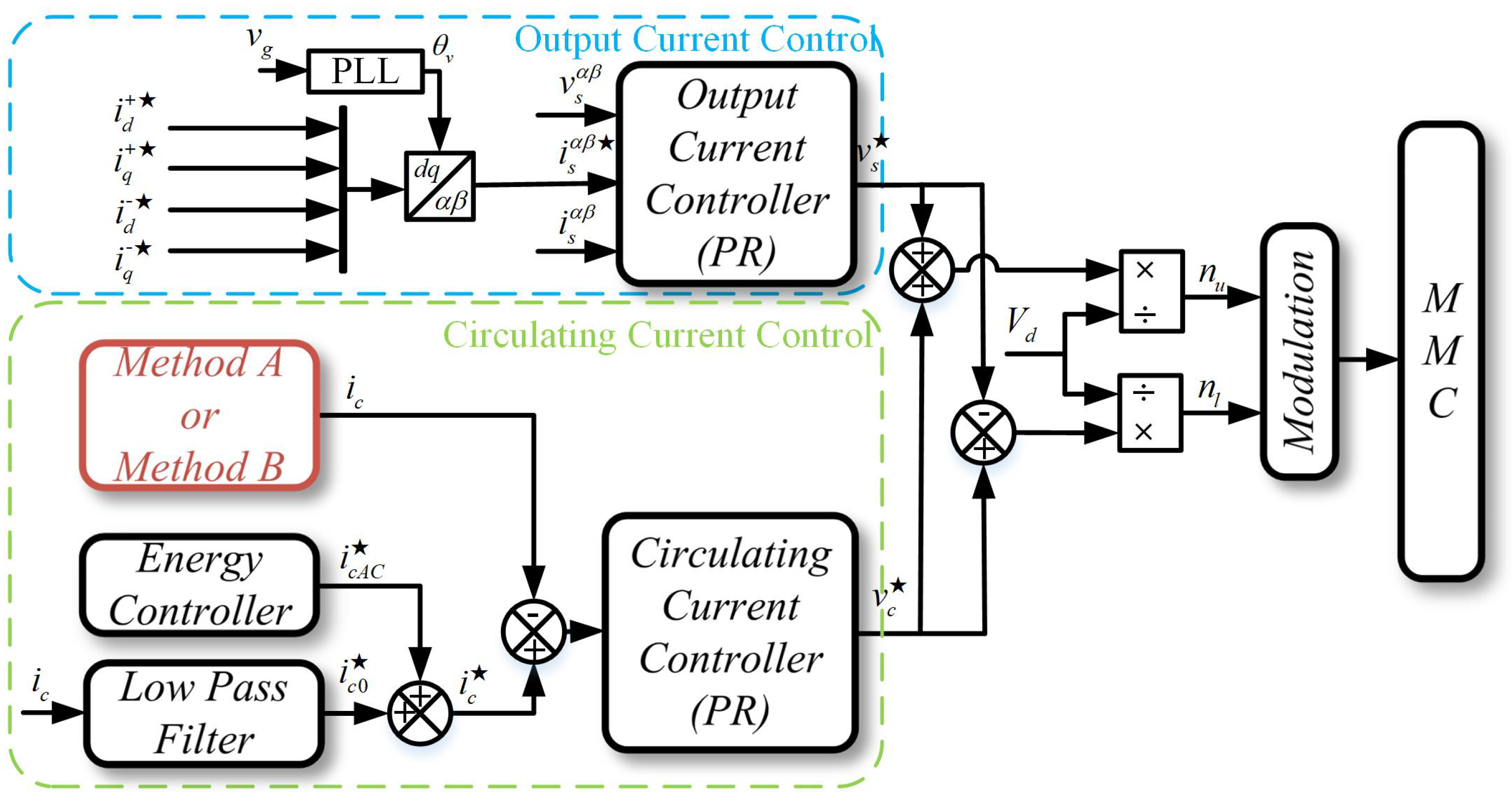
The proposed equations are an extension of the analytical method presented in [20]. In order to introduce the proposed analytical method in an easy and clear way, the block diagram (Figure 2) presents the capacitor voltage ripple derivation steps. In this paragraph, the basic process of derivation is briefly introduced. First, the unbalanced grid voltages and currents are detected and calculated for the next step. The positive-/negative-sequence forms of voltage/current components are applied in this paper. Second, based on the grid voltages and currents, the arm voltages and currents are calculated by the arm voltage/current definitions. Third, the arm power can be calculated by the arm voltages/currents; then, the arm energy (the calculation will be easier by dividing arm energy by sum energy and delta energy) can be derived by integrating the arm power. Finally, the submodule-capacitor voltage ripple can be derived by the relationship between the capacitor energy and capacitance. For the moment, the three-phase capacitor voltage ripples have been separately derived. In order to understand the relationship between phases A, B, and C, the symmetrical component method is used to identify the positive-/negative-/zero-sequence ripple components. In this way, the three-phase ripple can be seen as a whole system, not as three separate phases. The detailed derivation is given in the following.
Thus, the grid voltage ( v g k ) can be described as follows:
v g k = V ^ + 1 cos ( ω t 2 3 k π ) + V ^ 1 cos ( ω t 4 3 k π ) ,
in which ω is the grid’s fundamental frequency, V ^ + 1 and V ^ 1 are the amplitudes of the positive-sequence and negative-sequence components of the grid voltage, respectively, and k is the phase number (0 for A, 1 for B, an d2 for C). Similarly, the grid current can be described as follows:
i g k = I ^ + 1 cos ( ω t 2 3 k π + φ ) + I ^ 1 cos ( ω t 4 3 k π + φ ) .
The MMC’s upper and lower arm voltages ( v u k and v l k , respectively) can be defined by applying Kirchhoff’s law to the circuit shown in Figure 1:
v u k v l k = 1 2 v d v g k v z u k 1 2 v d + v g k v z l k ,
in which v d is the MMC DC-link voltage, and v z u k and v z l k are the voltage drops across the upper-arm and lower-arm impedances, respectively. The upper-arm and lower-arm currents ( i u k and i l k , respectively) are defined as follows:
i u k i l k = i c k + 1 2 i g k i c k 1 2 i g k ,
in which i c k is the MMC’s internal circulating current. In this paper, the undesired AC components of the circulating current are considered to be completely suppressed through a proper control technique, and thus, the circulating current is assumed to be a purely DC signal ( i c k = I c D C k ). The MMC’s upper-arm and lower-arm power ( p u k and p l k , respectively) can be calculated as follows:
p u k p l k = v u k · i u k v l k · i l k .
In order to facilitate the derivation of the analytical equations, the sum power ( P Σ k ) and delta power terms ( P Σ k and P Δ k , respectively) are defined as follows:
P Σ k P Δ k = p u k + p l k p u k p l k .
By substituting (1)–(6), the following two equations are obtained:
P Σ k = i c k v d 1 2 V ^ + 1 I ^ + 1 cos φ 1 2 V ^ + 1 I ^ 1 cos φ 1 2 V ^ 1 I ^ + 1 cos φ 1 2 V ^ 1 I ^ 1 cos φ 1 2 V ^ + 1 I ^ + 1 cos ( 2 ω t + θ v k + φ ) 1 2 cos V ^ 1 I ^ 1 ( 2 ω t + θ v k + φ ) 1 2 V ^ + 1 I ^ 1 cos ( 2 ω t φ ) 1 2 V ^ 1 I ^ + 1 cos ( 2 ω t + φ ) ,
and
P Δ k = 1 2 v d I ^ + 1 cos ( ω t + θ v k + + φ ) + 1 2 v d I ^ 1 cos ( ω t + θ v k φ ) 2 V ^ + 1 I c D C k cos ( ω t + θ v k + ) 2 V ^ 1 I c D C k cos ( ω t + θ v k ) .
It is important to notice that, since the grid voltage is unbalanced and the MMC DC-link voltage is constant, the DC component of the circulating current is different for each phase (each arm). In other words, the DC component of the circulating current of each phase should be calculated as follows:
I c D C k = P g k v d ,
in which P g k is the average value of the instantaneous grid power ( p g k ) for three phases. By integrating the sum and delta power (described in (7) and (8), respectively), the sum and delta energy ( W Σ k and W Δ k , respectively) are obtained as follows:
W Σ k = W Σ D C k V ^ + 1 I ^ + 1 sin ( 2 ω t + θ v k + φ ) 4 ω V ^ 1 I ^ + 1 sin ( 2 ω t + φ ) 4 ω Δ W Σ k ( 1 ) V ^ + 1 I ^ 1 sin ( 2 ω t φ ) 4 ω V ^ 1 I ^ 1 sin ( 2 ω t + θ v k + φ ) 4 ω Δ W Σ k ( 2 ) ,
and
W Δ k = W Δ D C k + v d I ^ + 1 sin ( ω t + θ v k + φ ) 2 ω + v d I ^ 1 sin ( ω t + θ v k φ ) 2 ω Δ W Δ k ( 1 ) ] 2 V + 1 I c D C k sin ( ω t + θ v k + ) ω 2 V ^ 1 I c D C k sin ( ω t + θ v k ) ω Δ W Δ k ( 2 ) .
The sum energy consists of two terms: the sum DC energy ( W Σ D C k ) and the sum AC energy. The sum AC energy is also composed of two terms: ( Δ W Σ k = Δ W Σ k ( 1 ) + Δ W Σ k ( 2 ) ). Similarly, the delta energy is composed of two terms: delta DC energy ( W Δ D C k ) and delta AC energy ( Δ W Δ k = Δ W Δ k ( 1 ) + Δ W Δ k ( 2 ) ). Similarly to (6), the sum energy and delta energy ( W u k and W l k , respectively) can be defined as functions of the upper-arm energy and lower-arm energy as follows:
W Σ k W Δ k = W u k + W l k W u k W l k .
The energy stored in the MMC capacitors can be calculated as follows:
W c u , l k i = C 2 ( v c u , l k i ) 2 ,
in which C is the submodule-capacitor capacitance, v c u , l k is the capacitor voltage, and i = 1 , 2 , . . . , N represents the submodule number in the MMC arm. In this paper, an average model is considered [20], in which all the capacitors in each MMC arm are represented by an equivalent capacitor with a capacitance equal to C N and with a voltage equal to the sum of each voltage in each submodule capacitor ( v c u , l k Σ ). This means that the upper-arm and lower-arm energies are equal to the energy in this equivalent capacitor. In other words:
W u , l k = C 2 N ( v c u , l k Σ ) 2 .
According to (14), the voltage in the equivalent capacitor can be calculated as follows:
v c u , l k Σ = 2 N C W u , l k .
As explained in [20], by calculating the upper-arm energy ( W u k ) and lower-arm energy ( W l k ) through (10)–(12) and by substituting these terms into (15), the following equations are obtained after some approximations:
v c u k Σ v d + N 2 C V d ( Δ W Σ k + Δ W Δ k )
and
v c l k Σ v d + N 2 C V d ( Δ W Σ k Δ W Δ k ) .
Equations (16) and (17) are composed of a DC term and of an AC term. The DC term corresponds to the average voltage value in the equivalent capacitor, whereas the AC term corresponds to the ripple in the equivalent capacitor. The two AC terms in (16) and (17) are defined as follows:
v c k ( Δ W Σ ) Σ = N 2 C V d Δ W Σ k
and
v c k ( Δ W Δ ) Σ = N 2 C V d Δ W Δ k .
By substituting the terms of (10) and (11) into (18) and (19), the following is obtained:
v c k ( Δ W Σ ) Σ = N 2 C V d V ^ + 1 I ^ + 1 sin ( 2 ω t + θ v k + φ ) 4 ω N e g a t i v e s e q u e n c e c o m p o n e n t V ^ 1 I ^ 1 sin ( 2 ω t + θ v k + φ ) 4 ω P o s i t i v e s e q u e n c e c o m p o n e n t + N 2 C V d V ^ + 1 I ^ 1 sin ( 2 ω t φ ) 4 ω V ^ 1 I ^ + 1 sin ( 2 ω t + φ ) 4 ω Z e r o s e q u e n c e c o m p o n e n t
and
v c k ( Δ W Δ ) Σ = N 2 C V d 1 2 ω V d I ^ + 1 sin ( ω t + θ v k + φ ) P o s i t i v e s e q u e n c e c o m p o n e n t + 1 2 ω V d I ^ 1 sin ( ω t + θ v k φ ) N e g a t i v e s e q u e n c e c o m p o n e n t + N 2 C V d 2 ω V ^ + 1 i c D C k sin ( ω t + θ v k + ) D e l t a r i p p l e p a r t 1 2 ω V ^ 1 i c D C k sin ( ω t + θ v k ) D e l t a r i p p l e p a r t 2 .
In this paper, it is considered that the MMC output current is controlled in such a way as to be composed of only the positive-sequence component, even under the unbalanced grid conditions. In other words, the negative-sequence component is compensated ( I ^ 1 = 0 ) through a control action. Thus, some terms of (20) and (21) are eliminated, resulting in the following two equations:
v c k ( Δ W Σ ) Σ = N 2 C V d V ^ + 1 I ^ + 1 sin ( 2 ω t + θ v k + φ ) 4 ω N e g a t i v e s e q u e n c e c o m p o n e n t V ^ 1 I ^ + 1 sin ( 2 ω t + φ ) 4 ω Z e r o s e q u e n c e c o m p o n e n t
and
v c k ( Δ W Δ ) Σ = N 2 C V d 1 2 ω V d I ^ + 1 sin ( ω t + θ v k + φ ) P o s i t i v e s e q u e n c e c o m p o n e n t + N 2 C V d 2 ω V ^ + 1 I c D C k sin ( ω t + θ v k + ) D e l t a r i p p l e 1 2 ω V ^ 1 I c D C k sin ( ω t + θ v k ) D e l t a r i p p l e 2 .
In other words, even if all the control actions are taken to compensate for the negative-sequence grid voltage and to suppress all the undesired AC components of the converter’s circulating current, still, the submodule-capacitor ripple will be composed of the terms described in (22) and (23). There are two additional ripple terms in comparison to the balanced grid case, which are caused by the negative-sequence grid voltage ( V ^ 1 ). In other words, under balanced grid conditions, the MMC’s submodule-capacitor voltage ripple would be identical to the one described by (22) and (23) if the two terms containing V ^ 1 were removed. The ripple behavior under balanced grid conditions is demonstrated in [20]. The MMC’s submodule-capacitor voltage ripple under unbalanced grid conditions (described through Equations (22) and (23)) is illustrated in Figure 3.
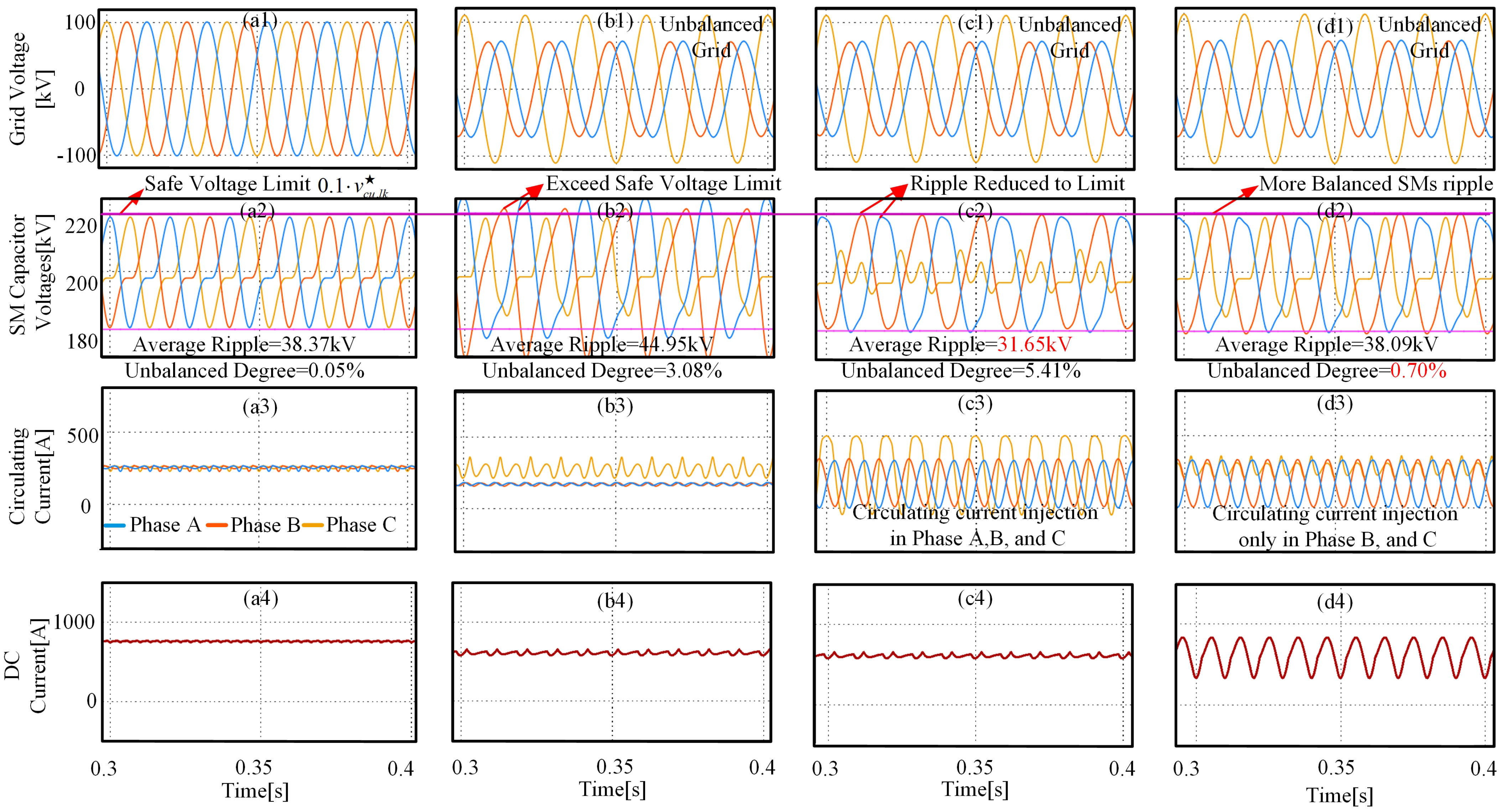
In order to validate the analytical equations proposed in this paper, a simulation was carried out with the Simulink/Matlab software. In this simulation, the MMC was modeled according to Figure 1. In order to calculate the equations obtained in this paper, the block diagram illustrated in Figure 2 was also implemented in Simulink/Matlab. The MMC parameters used in both simulations are the ones described in Table 1.
The results obtained in the simulations with the real system (illustrated in Figure 1) and with the proposed analytical method (represented by the block diagram shown in Figure 2) are depicted in Figure 4. By analyzing this figure, it becomes clear that the analytical description of the MMC’s submodule-capacitor voltage under unbalanced grid conditions is very precise, as the simulation results match with high accuracy.

3. Submodule-Capacitor Voltage Ripple Reduction Methods

After the derivation of the submodule-capacitor voltage equations in Section 2, in this section, the submodule-capacitor voltage ripple reduction methods based on the derived equations will be proposed. From Equations (22) and (23), we can conclude that the following variables affect the submodule-capacitor voltage: positive-sequence grid voltage ( V ^ + 1 ), negative-sequence grid voltage ( V ^ 1 ), positive-sequence output current ( I ^ + 1 ), DC voltage ( V d ), and DC component of the circulating current ( I c D C k ). All these variables are imposed by grid codes or cannot be changed. In order to optimize the submodule-capacitor voltage in (22) and (23), a new variable should be selected. Injecting AC circulating current is a suitable choice for reducing the submodule-capacitor voltage. Circulating current is a current that flows internally in the converter, and it only affects the internal behavior of the MMC. Now, the circulating current is defined as containing both DC and AC components as follows:
i c k = i u k + i l k 2 = i c D C k + i c A C k .
Based on [21], the submodule-capacitor voltage ripple can be reduced by injecting AC circulating currents under balanced grid conditions. However, these methods are only designed for the balanced case, as they disregard the unbalanced grid conditions. In the following subsection, the AC component of the MMC’s circulating current is also considered to derive the equations of the submodule-capacitor voltages, since, in Section 2, the AC component was disregarded, as the circulating current was considered to be only composed of the DC component. This way, the proper amplitude of the AC component of the circulating current can be calculated, which is the optimum one required to reduce the submodule-capacitor voltage ripple.

3.1. Submodule-Capacitor Voltage Balancing Method A

The definition of circulating current is that it is a current that flows in the same direction through both the MMC’s upper and lower arms. Thus, the circulating current charges the submodule capacitors of the upper and of the lower arm equally. So, the circulating current only affects the sum capacitor voltage ripple, as described in (22). In this paper, the AC circulating current injected for the voltage-ripple compensation is composed of a negative-sequence double-frequency component ( I ^ c A C 2 ) and a zero-sequence double-frequency component ( I ^ c A C 0 ). These circulating-current components can eliminate the sum capacitor voltage ripple, as described below. The first compensation technique proposed in this paper consists of considering the MMC circulating current to be equal to:
i c k = I c D C k + I ^ c A C 2 cos ( 2 ω t + θ v k ) + I ^ c A C 0 cos ( 2 ω t ) .
By substituting (25) into (4) and by repeating the derivation steps of Section 2, the new equation that describes the sum capacitor term is the following:
v c k ( Δ W Σ ) Σ = N 2 C V d V d I ^ c A C 2 k sin ( 2 ω t + θ v k ) 2 ω V ^ + 1 I ^ + 1 sin ( 2 ω t + θ v k + φ ) 4 ω N e g a t i v e s e q u e n c e s u m r i p p l e
+ N 2 C V d V d I ^ c A C 0 k sin ( 2 ω t ) 2 ω V ^ 1 I ^ + 1 sin ( 2 ω t + φ ) 4 ω Z e r o s e q u e n c e s u m r i p p l e .
The new equation that describes the MMC’s sum capacitor voltage is composed of terms that have the same frequency and phase angle; thus, these terms can cancel each other out if the proper amplitudes of the circulating-current components are set. The proper amplitudes of the circulating components are the following:
I ^ c A C 2 k = V ^ + 1 I ^ + 1 2 V d , I ^ c A C 0 k = V ^ 1 I ^ + 1 2 V d .
Thus, the reference signal of the AC circulating current to be injected for the submodule-capacitor voltage-ripple compensation is the following:
I c A C k * = I ^ c A C 2 k cos ( 2 ω t + θ v k ) + I ^ c A C 0 k cos ( 2 ω t ) .
If the current represented in (28) is injected, then the sum submodule-capacitor voltage ripple ( v c k ( Δ W Σ ) Σ ) will be null. This fact can be confirmed by substituting (27) into (26). Since an arbitrary unbalanced grid can be represented by the combination of positive- and negative-sequence components, then this method is a universal approach for reducing the capacitor voltage ripple under unbalanced grid conditions. The advantage of this method in relation to the one proposed in [24] is that, in [24], only the negative-sequence double-fundamental component is injected, whereas in this paper, the zero-sequence component is also considered in the injected circulating current. Thus, an improved compensation is obtained. The method proposed in this subsection is illustrated in Figure 5.

3.2. Submodule-Capacitor Voltage Balancing Method B

As shown in Figure 4, the amplitude of the submodule-capacitor voltage ripple in phases B and C exceeds its limit, which is equal to 10% of the submodule-capacitor’s rated voltage. The submodule-capacitor voltage ripple in phase A is still within the allowed range. That is to say, the submodule capacitors in phase A can still work in a safe fashion without any circulating current injection. In other words, intuitively, there is no need to inject circulating current in phase A to reduce the ripple. Only injecting circulating current in phase B and C is enough to limit the submodule-capacitor voltage ripple within the safe limits. The block diagram of Method B is shown in Figure 6. When the submodule-capacitor voltage ripple of one phase exceeds its limit, then circulating current is injected in this phase only in order to limit the voltage ripple. The circulating current to be injected is the one described in (28), which is same as in Method A. If the submodule-capacitor voltage ripple of a given phase does not exceed its limit, no circulating current is injected into this phase.

4. Results

Before showing the simulation and experimental results of the proposed method, the structure of the MMC controller is introduced below. The structure of the MMC controller is presented in Figure 7. Two variables of the MMC need to be controlled: the circulating current and the output current. Therefore, two independent controllers are needed: the circulating-current controller, which is responsible for making sure that all the undesired AC components are properly suppressed, and the output-current controller, which is responsible for tracking the desired reference. In this paper, the AC circulating-current components are injected according to Method A and Method B. The circulating-current control is able to properly track the AC components, since it is based on a proportional resonance (PR) controller. An energy controller is also part of the circulating-current control, which is necessary for making sure that the MMC’s upper and lower arms have equal voltage values.

4.1. Simulation Results

The simulation of a grid-connected MMC was carried out to validate the proposed compensation algorithms. The parameters of the simulation model were the ones shown in Table 1. To simplify the simulation, the average arm model was used [20], which consisted of considering the MMC arm to be composed of only one submodule with a capacitance value equal to C N and with a voltage equal to v c u , l k Σ .
In Figure 8, there are four columns to show the MMC capacitor voltages in four different conditions. The four conditions are: (a) balanced grid, (b) unbalanced grid without circulating current injection, (c) the results of Method A, and (d) the results of method B, respectively. At first glance, the ripples in conditions c and d are lower than in condition b and are below the safe limit. This means that the proposed methods are effective. In the following, a detailed quantitative description of the simulation results is introduced.
In Figure 8(a1–a3) the grid voltages, capacitor voltages, and circulating currents under a balanced grid are shown, respectively. By observing Figure 8(a1), one can notice that the grid voltage is, in fact, a three-phase symmetrical signal with an amplitude equal to 100 kV. Thus, as shown in Figure 8(a2), the submodule-capacitor voltages are also symmetrical, and all the capacitor voltages are within the safe limits (10% of the submodule-capacitor voltage’s nominal value, which is equal to 220 kV). The undesired AC components of the circulating currents are suppressed, and thus, the circulating current is purely DC. Detailed numbers are shown in Table 2.
In Figure 8(b1–b3), the simulation results of the MMC under unbalanced grid conditions are shown. The amplitudes of the positive-sequence and negative-sequence components are 0.8 V s ^ and 0.4 V s ^ , respectively. According to Figure 8(b2), the capacitor voltages in phases B (222.45 kV) and C (225.32 kV) are higher than the safe voltage limit (220 kV). In this case, the MMC will trip because of the overvoltages in the submodule capacitors. The imbalance degree (ID) of the submodule-capacitor voltage ripple is defined in Equation (29). In this case, ID = 3.08%, and the average capacitor voltage ripple is 44.96 kV. As shown in Figure 8(b3), the circulating currents are affected by the unbalanced grid.
I D = m a x ( V a , V b , V c ) m i n ( V a , V b , V c ) V a v g , V a v g = V a + V b + V c 3 .
In Figure 8(c1–c3), the simulation results of the MMC under unbalanced grid conditions and with the proposed Method A enabled are shown. The circulating-current components calculated according to (28) are injected into the MMC, as shown in Figure 8(c3). Thus, the capacitor-voltage ripple is significantly reduced, especially in phase A, as Figure 8(c2) shows. The average submodule-capacitor voltage ripple is reduced to 31.65 kV, which corresponds to a 29.6% reduction in comparison to the case without circulating-current injection. The ID is 5.41% in this case.
In Figure 8(d1–d3), the simulation results of the MMC under unbalanced grid conditions and with the proposed Method B enabled are shown. Since the capacitor-voltage ripple in phase A does not exceed the safe limits, the circulating currents do not need to be injected into phase A. Therefore, circulating currents are only injected into phases B and C, as illustrated in Figure 8(d3). The average submodule-capacitor voltage ripple is reduced to 38.09 kV and the ID is equal to only 0.7% in this case.
To sum up, the average submodule-capacitor voltage ripple is reduced with both Method A and Method B in comparison to the case without circulating-current injection. The low average ripple obtained through Method A is mainly due to the fact that the ripple of phase A is considerably reduced. However, the ripple reduction in phase A is unnecessary, since this ripple never exceeds the safe voltage limits, even in the case without circulating-current injection. The injection of circulating currents in phase A will only contribute to increased losses in the MMC. Thus, a conclusion of this paper is that Method B is more recommendable for achieving a more balanced submodule-capacitor voltage and lower losses.

4.2. Experimental Results

To evaluate the performance of the proposed ripple-reduction methods, experimental results are presented in this section. The experiment was carried out in a low-scale three-phase grid-connected MMC test setup with four half-bridge SMs per arm. The parameters of the experimental setup are shown in Table 1. The control was implemented using a dSPACE DS1006 board. The experimental setup worked as a three-phase MMC inverter. The level-shifted-carrier modulation method was applied with the sort and select algorithm. The switching frequency was equal to 2 kHz in this experiment. Figure 9 shows the experimental setup of the MMC.
Similarly to the simulation results, the submodule-capacitor voltage ripple became unbalanced when the MMC was connected to an unbalanced grid. This result is shown in Figure 10(b2), in which the amplitude of the submodule-capacitor voltage ripple in phases B and C was equal to 30.3 V. The average ripple was equal to 2.07 V. The ID was equal to 1.28%. Moreover, as illustrated in Figure 10(b2), the three-phase capacitor voltages had an unbalanced non-periodic waveform, since the energy of three phases was not balanced if no circulating currents were injected into the MMC.
In Figure 10(c2), the submodule-capacitor voltage is shown for the case in which circulating currents were injected according to Method A. The average submodule-capacitor voltage ripple was reduced from 2.07 to 1.19 V. In this case, the submodule-capacitor voltages in phases B and C were within the safe voltage limits. The ID was equal to 1.11% in this case. The imbalance level of the MMC submodule-capacitor voltages was further reduced when the compensation Method B was used, as illustrated in Figure 10(d2). The ID was decreased to 0.42% in this case. A summary of the results obtained through the experiment is shown in Table 3.

5. Conclusions

In this paper, a new solution for mitigating the high submodule-capacitor voltage ripple of an MMC under unbalanced grid conditions was proposed. The contributions of this paper are twofold. First, the analytical equations for the submodule-capacitor voltage were proposed. The three-phase components were identified with the analytical equations. Secondly, two compensation methods were proposed to mitigate the high submodule-capacitor voltage ripple under unbalanced grid conditions. These methods are based on the injection of specific circulating-current components. These circulating-current components can be calculated through the proposed analytical model in a straightforward manner. With the proposed method, engineers will have a better understanding of the imbalance mechanism of submodule-capacitor voltage, and can easily make sure that MMCs’ capacitors always work within safe voltage ranges, even if the grid is unbalanced. However, although this method can ensure the stable operation of an MMC, it will cause losses due to the insertion of circulating current during short fault periods. Nevertheless, this method is still a very competitive solution for ensuring the stable operation of an MMC. In the event of a grid failure, ensuring the survival of the grid is the most important thing, and the duration of the grid failure is generally very short, so the additional loss will not bring a significant cost increase.

Author Contributions

Conceptualization, S.W., S.C. and R.T.; methodology, S.W.; software, S.W.; validation, S.W., G.G.; formal analysis, S.W., D.B.; investigation, S.W., D.B.; resources, R.T., D.B.; data curation, S.W.; writing—original draft preparation, S.W.; writing—review and editing, S.W., D.B., G.G.; visualization, S.W.; supervision, S.C. and R.T.; project administration, R.T.; funding acquisition, S.W. and R.T. Authorship must be limited to those who have contributed substantially to the work reported. All authors have read and agreed to the published version of the manuscript.

Funding

This research received no external funding.

Conflicts of Interest

The authors declare no conflict of interest.

References

  1. Ahmadijokani, M.; Mehrasa, M.; Sleiman, M.; Sharifzadeh, M.; Sheikholeslami, A.; Al-Haddad, K. A Back-Stepping Control Method for Modular Multilevel Converters. IEEE Trans. Ind. Electron. 2020, 68, 443–453. [Google Scholar] [CrossRef]
  2. Mehrasa, M.; Pouresmaeil, E.; Zabihi, S.; Catalão, J.P. Dynamic model, control and stability analysis of MMC in HVDC transmission systems. IEEE Trans. Power Deliv. 2016, 32, 1471–1482. [Google Scholar] [CrossRef]
  3. Gontijo, G.; Wang, S.; Kerekes, T.; Teodorescu, R. New AC–AC Modular Multilevel Converter Solution for Medium-Voltage Machine-Drive Applications: Modular Multilevel Series Converter. Energies 2020, 13, 3664. [Google Scholar] [CrossRef]
  4. Ou, Z.; Wang, G.; Zhang, L. Modular multilevel converter control strategy based on arm current control under unbalanced grid condition. IEEE Trans. Power Electron. 2017, 33, 3826–3836. [Google Scholar] [CrossRef]
  5. Guo, C.; Yang, J.; Zhao, C. Investigation of small-signal dynamics of modular multilevel converter under unbalanced grid conditions. IEEE Trans. Ind. Electron. 2018, 66, 2269–2279. [Google Scholar] [CrossRef]
  6. Lesnicar, A.; Marquardt, R. An innovative modular multilevel converter topology suitable for a wide power range. In Proceedings of the 2003 IEEE Bologna Power Tech Conference Proceedings, Bologna, Italy, 23–26 June 2003; Volume 3. [Google Scholar]
  7. Rohner, S.; Bernet, S.; Hiller, M.; Sommer, R. Modulation, losses, and semiconductor requirements of modular multilevel converters. IEEE Trans. Ind. Electron. 2009, 57, 2633–2642. [Google Scholar] [CrossRef]
  8. Wang, K.; Li, Y.; Zheng, Z.; Xu, L. Voltage balancing and fluctuation-suppression methods of floating capacitors in a new modular multilevel converter. IEEE Trans. Ind. Electron. 2012, 60, 1943–1954. [Google Scholar] [CrossRef]
  9. Wang, S.; Alsokhiry, F.S.; Adam, G.P. Impact of submodule faults on the performance of modular multilevel converters. Energies 2020, 13, 4089. [Google Scholar] [CrossRef]
  10. Antonopoulos, A.; Angquist, L.; Nee, H.P. On dynamics and voltage control of the modular multilevel converter. In Proceedings of the 2009 13th European Conference on Power Electronics and Applications, Barcelona, Spain, 8–10 September 2009; pp. 1–10. [Google Scholar]
  11. Nami, A.; Liang, J.; Dijkhuizen, F.; Demetriades, G.D. Modular multilevel converters for HVDC applications: Review on converter cells and functionalities. IEEE Trans. Power Electron. 2014, 30, 18–36. [Google Scholar] [CrossRef]
  12. Guan, M.; Xu, Z. Modeling and control of a modular multilevel converter-based HVDC system under unbalanced grid conditions. IEEE Trans. Power Electron. 2012, 27, 4858–4867. [Google Scholar] [CrossRef]
  13. Tu, Q.; Xu, Z.; Chang, Y.; Guan, L. Suppressing DC voltage ripples of MMC-HVDC under unbalanced grid conditions. IEEE Trans. Power Deliv. 2012, 27, 1332–1338. [Google Scholar] [CrossRef]
  14. Moon, J.W.; Kim, C.S.; Park, J.W.; Kang, D.W.; Kim, J.M. Circulating current control in MMC under the unbalanced voltage. IEEE Trans. Power Deliv. 2013, 28, 1952–1959. [Google Scholar] [CrossRef]
  15. Moon, J.W.; Park, J.W.; Kang, D.W.; Kim, J.M. A control method of HVDC-modular multilevel converter based on arm current under the unbalanced voltage condition. IEEE Trans. Power Deliv. 2014, 30, 529–536. [Google Scholar] [CrossRef]
  16. Shi, X.; Li, Y.; Wang, Z.; Liu, B.; Tolbert, L.M.; Wang, F. Steady-state analysis of modular multilevel converter (MMC) under unbalanced grid conditions. In Proceedings of the 2016 IEEE Applied Power Electronics Conference and Exposition (APEC), Long Beach, CA, USA, 20–24 March 2016; pp. 2637–2644. [Google Scholar]
  17. Ilves, K.; Norrga, S.; Harnefors, L.; Nee, H.P. On energy storage requirements in modular multilevel converters. IEEE Trans. Power Electron. 2013, 29, 77–88. [Google Scholar] [CrossRef]
  18. Ronanki, D.; Williamson, S.S. Failure prediction of submodule capacitors in modular multilevel converter by monitoring the intrinsic capacitor voltage fluctuations. IEEE Trans. Ind. Electron. 2019, 67, 2585–2594. [Google Scholar] [CrossRef]
  19. Harnefors, L.; Antonopoulos, A.; Norrga, S.; Angquist, L.; Nee, H.P. Dynamic analysis of modular multilevel converters. IEEE Trans. Ind. Electron. 2012, 60, 2526–2537. [Google Scholar] [CrossRef]
  20. Sharifabadi, K.; Harnefors, L.; Nee, H.P.; Norrga, S.; Teodorescu, R. Design, Control, and Application of Modular Multilevel Converters for HVDC Transmission Systems; John Wiley & Sons: Hoboken, NJ, USA, 2016. [Google Scholar]
  21. Ilves, K.; Antonopoulos, A.; Harnefors, L.; Norrga, S.; Ängquist, L.; Nee, H.P. Capacitor voltage ripple shaping in modular multilevel converters allowing for operating region extension. In Proceedings of the IECON 2011-37th Annual Conference of the IEEE Industrial Electronics Society, Melbourne, VIC, Australia, 7–10 November 2011; pp. 4403–4408. [Google Scholar]
  22. Pou, J.; Ceballos, S.; Konstantinou, G.; Agelidis, V.G.; Picas, R.; Zaragoza, J. Circulating current injection methods based on instantaneous information for the modular multilevel converter. IEEE Trans. Ind. Electron. 2014, 62, 777–788. [Google Scholar] [CrossRef] [Green Version]
  23. Li, J.; Konstantinou, G.; Wickramasinghe, H.R.; Townsend, C.D.; Pou, J. Capacitor Voltage Reduction in Modular Multilevel Converters under Grid Voltages Unbalances. IEEE Trans. Power Deliv. 2019, 35, 160–170. [Google Scholar] [CrossRef]
  24. Vasiladiotis, M.; Cherix, N.; Rufer, A. Impact of grid asymmetries on the operation and capacitive energy storage design of modular multilevel converters. IEEE Trans. Ind. Electron. 2015, 62, 6697–6707. [Google Scholar] [CrossRef]
  25. Teodorescu, R.; Liserre, M.; Rodriguez, P. Grid Converters for Photovoltaic and Wind Power Systems; John Wiley & Sons: Hoboken, NJ, USA, 2011; Volume 29. [Google Scholar]
Figure 1. Modular multilevel converter (MMC) topology diagram.
Energies 14 00651 g001
Figure 2. Block diagram of the analytical derivation of the submodule-capacitor voltage.
Energies 14 00651 g002
Figure 3. Illustration of the MMC’s submodule-capacitor voltage-ripple components under unbalanced grid conditions.
Energies 14 00651 g003
Figure 4. Estimated submodule-capacitor voltages and the simulated submodule-capacitor voltages.
Energies 14 00651 g004
Figure 5. Block diagram of Method A.
Energies 14 00651 g005
Figure 6. Block diagram of Method B.
Energies 14 00651 g006
Figure 7. The structure of the proposed MMC controller.
Energies 14 00651 g007
Figure 8. Simulation results. (a) balanced grid, (a1) balanced grid voltages; (a2) balanced SM ripple; (a3) circulating current; (a4) DC current. (b) unbalanced grid without circulating current injection. (b1) unbalanced grid voltages; (b2) unbalanced SM ripple; (b3) circulating current; (b4) DC current. (c) the results of Method A.(c1) unbalanced grid voltages; (c2) SM ripple; (c3) circulating current; (c4) DC current. (d) the results of Method B. (d1) unbalanced grid voltages; (d2) SM ripple; (d3) circulating current; (d4) DC current.
Energies 14 00651 g008
Figure 9. Experimental MMC setup.
Energies 14 00651 g009
Figure 10. Experimental results. (a) balanced grid, (a1) balanced grid voltages; (a2) balanced SM ripple; (a3) circulating current; (a4) DC current. (b) unbalanced grid without circulating current injection. (b1) unbalanced grid voltages; (b2) unbalanced SM ripple; (b3) circulating current; (b4) DC current. (c) the results of Method A.(c1) unbalanced grid voltages; (c2) SM ripple; (c3) circulating current; (c4) DC current. (d) the results of Method B.(d1) unbalanced grid voltages; (d2) SM ripple; (d3) circulating current; (d4) DC current.
Energies 14 00651 g010
Table 1. MMC parameters.
SimulationExperiment
Submodule number in one arm (N)1004
DC-line voltage200 kV200 V
Active power150 MW1 kW
Submodule capacitance (C)3.75 mF2000 uF
Submodule capacitor voltage (Vc)2 kV50 V
AC system frequency50 Hz50 Hz
Inductance in the arm50.9 mH10 mH
Sampling frequency10k Hz10k Hz
Amplitude of the grid100 kV83 V
Table 2. Submodule-capacitor voltage ripple values of the proposed methods.
Normal GridNo InjectionMethod AMethod B
Average Ripple38.37 kV44.96kV31.65 kV38.09 kV
Amplitude A218.3 kV218.41 kV207.9 kV218.6 kV
Amplitude B218.2 kV222.4 kV219.8 kV219.9 kV
Amplitude C218.3 kV225.3 kV218.9 kV218.5 kV
Unbalanced Degree0.05%3.08%5.41%0.70%
Table 3. Submodule-capacitor voltage ripple values of the proposed methods: experiment.
Normal GridNo InjectionMethod AMethod B
Average Ripple1.58 V2.07 V1.19 V1.48 V
Amplitude A30.92 V30.90 V30.55 V30.95 V
Amplitude B30.85 V31.30 V30.83 V30.82 V
Amplitude C30.90 V31.30 V30.89 V30.90 V
Unbalanced Degree0.23%1.28%1.11%0.42%
Publisher’s Note: MDPI stays neutral with regard to jurisdictional claims in published maps and institutional affiliations.

