
Electrochemical Properties of Porous Graphene/Polyimide-Nickel Oxide Hybrid Composite Electrode Material

Department of Chemical and Materials Engineering, University of Cincinnati, Cincinnati, OH 45221, USA
*
Author to whom correspondence should be addressed.
Energies 2021, 14(3), 582; https://doi.org/10.3390/en14030582
Submission received: 18 December 2020
/
Revised: 16 January 2021
/
Accepted: 17 January 2021
/
Published: 23 January 2021
(This article belongs to the Section D1: Advanced Energy Materials)
Abstract
:Polyimide-graphene nanosheet composite electrodes are rigid and dense and, therefore, exhibit moderate electrochemical properties. The electrochemical properties of polyimide-graphene nanosheet electrodes were remarkably improved by creating voids in the composite followed by the insertion of nickel oxide into the composites. Nickel oxide particles were electrodeposited onto the porous graphene/poly(amic acid) composite, containing poly (acrylic resin). The hybrid composite was then subjected to thermal treatment at ≥ 300 °C to simultaneously complete imidization and degrade the poly (acrylic resin). Cyclic Voltammetry (CV) and electrochemical impedance spectroscopy (EIS) were used to study the eletrochemical properties of the composite electrode material. It is shown that remarkable improvement in the electrochemical behavior of the hybrid composite occurred due to the removal of poly(acrylic acid) and the insertion of NiO particles into the polyimide matrix. Fourier Transform Infrared Spectroscopy (FTIR) spectra of the hybrid composites show distinct characteristic peaks for polyimide and NiO in the hybrid composite electrode. Scanning Electron Microscopy, SEM images of the composites, show the presence of NiO aggregates in the composite material. Compared to neat graphene/polyimide composite electrode (GR/PI) composites, the specific capacitance of the hybrid composite electrode increased remarkably by over 250% due to the high interfacial surface area provided by NiO and the concomitant improvement in the electrode–electrolyte interaction.
1. Introduction
Electrochemical capacitors have generated much interest as energy storage devices due to their instantaneous power output and excellent charge/discharge capabilities. Unlike batteries, they exhibit higher power density with instantaneous charge/discharge capabilities, however, they show very low energy density. Lately, many efforts have been directed to discovering cheaper and readily available materials for use in energy storage technology. Carbon-based materials, such as activated carbon, carbon nanotube (CNT) and graphene, are used in super-capacitor design due to their high electric double layer capacitances. Other materials, such as conducting polymers and transition metal oxides, such as ruthenium oxide, manganese oxide, cobalt oxide and nickel oxide, also find application in design because they demonstrate excellent Faradaic charge transfer mechanisms that yield excellent pseudo-capacitance values as high as 1200 F/g. Several reports have been written about the use of graphene–polymer composites as an electrode material due to their low cost, ease of design, flexibility and environmental friendliness [1,2,3,4]. Graphene–polymer composites specifically have found particular interest in this space because of the ease of graphene dispersion in most polymers [1,2,3,4]. Such composites possess both excellent mechanical and thermal stability and hence they are attractive for use in flexible standalone electrodes. Graphene/polyimide (GR/PI) composites are currently being studied by our group [1] for use in supercapacitor applications, especially in devices where high-end-use temperature is required.
GR/PI composites show very poor electrochemical behavior due to their dense morphology and compactness. The presence of a rigid graphene filler phase embedded in a very dense insulating polyimide matrix restricts the transport of ions such that the ions are unable to make contact with active graphene fillers. Previous published work shows how the composite’s morphology can be improved to enable better ion transport in anode materials for batteries [5] and supercapacitors [1]. The deposition of a transition metal oxide, such as nickel oxide, ruthenium oxide, and manganese oxide, onto carbon-based substrates, such as activated carbon, CNT, and carbon fibers, has resulted in a significant improvement in specific capacitance and excellent power capabilities [6,7]. In particular, studies show that NiO-based composites, such as NiO/C and Ni/NiO/C, exhibit high specific capacitance and good power characteristics attributed to combination of different charge storage mechanisms [6,7]. Unlike other transition metal oxides, nickel oxide has generated much interest due to its high theoretical capacitance of 2573F/g, low cost, low toxicity and availability. This makes nickel oxide (NiO) a promising candidate for alkaline electrochemical capacitors. In order to process the porous electrode material, several techniques, such as chemical precipitation, reactive radiofrequency (rf) sputtering, calcining and electrochemical deposition, have been used [6,7,8,9,10,11]. Among these synthetic methods, the electrochemical deposition technique has one important advantage over the others: the weight and thickness of the metal oxide film are easily controlled by controlling the electrodeposition parameters, such as the current density, bath composition, and bath temperature [12,13].
Porosity is a crucial factor in determining the capacitive behavior of NiO. This is because it is important for ions to be transported rapidly through the film during high rate of charging and discharging. It has been reported that the nickel oxide structure with particulate/aggregated morphology produce specific capacitances that are much below the theoretical capacitance value [10]. To achieve higher energy and power density, NiO nanostructures with open pores have been synthesized and they demonstrated higher supercapacitor performance [14,15,16,17,18,19,20]. Studies show that dissimilarities in electrode/electrolyte interfaces with different morphologies and microstructures result in substantial differences in electrochemical performance [11].
The deposition of NiO on the GR/PI composite electrode to form the NiO-GR/PI hybrid electrode will combine the advantage of the highly pseudo-capacitive behavior of NiO and the double layer capacitive behavior of graphene. In this work, nickel hydroxide is electrochemically deposited onto a porous graphene/polyimide film and thermally heated up to 330 °C for 1 h to form nickel oxide. Several characterization techniques, including cyclic voltammetry (CV), electrochemical impedance spectroscopy (EIS) and cyclic charge discharge (CCD) technique, were used to study the electrochemical properties of the composite. Xray diffraction (XRD), Raman and FTIR spectroscopy were used to study the structure of the composite, while scanning electron microscopy (SEM) was used to study the morphology of the composites. We have compared the properties of the NiO-GR/PI hybrid composite with that of the neat GR/PI composites.
2. Materials and Methods
The materials used in this study include: nano-graphene sheets (98.48% purity) with thickness of 50–100 nm and length 7 mm, purchased from Angstron materials, Dayton, Ohio. Pyromellitic dianhydride (PMDA) (99% purity), 4,4-oxydianiline (ODA) (99% purity) and N-methyl-pyrrolidone (NMP) (99% purity) were purchased from Sigma-Aldrich company and poly(acrylic acid) resin with a glass transition temperature of 30 °C and viscosity of 105 cP was obtained from Mallard Creek Polymers Inc. Nickel oxide precursors, including nickel sulphate (99.99% purity), sodium sulphate (99% purity) and sodium acetate (99% purity), were purchased from Sigma Aldrich Inc.
2.1. Synthesis of Flexible Porous Graphene/Polyimide Films
The synthesis of GR/PI composite film was performed by using 0.05 g poly(acrylic acid) resin corresponding to 1 wt% of resin. The resin was added to a round-bottom flask containing 100 mL of NMP and mechanically stirred for 15 min, then 5.1608 g of ODA was added to the stirring mixture, followed by continuous mechanical stirring for 30 min. Then, 10.782 g (50 wt%) of nano-graphene powder was added to the mixture in a gradual steady manner and stirring speed was increased. After 8 h of stirring, 5.6216 g of PMDA was added to the mixture and mechanical stirring continued for another 12 h while the temperature was maintained at 10 °C in a temperature-controlled bath. All these procedures were carried out under an inert atmosphere with a steady purge of nitrogen gas. The same procedures were followed in the synthesis of neat GR/PI composite except the addition of poly(acrylic acid) resin, which was omitted. Free standing films were prepared by using the solution casting method. The reaction solution was cast onto a clean glass substrate and thermally imidized in a step-wise manner in a Fisher scientific iso-temp vacuum oven with pressure 100 psi (model 281A) at 120 °C for 2 h, 200 °C for 1 h, 250 °C for 1 h and 300 °C for 4 h. The cast films were delaminated using a sharp blade and subsequently stored in a transparent zip lock bag.
2.2. Electrochemical Deposition of NiO on Porous Graphene/Polyimide Films
Nickel oxide was deposited on both sides of porous composite film measuring (0.3 cm × 0.5 cm) immersed in a stirring mixture of 0.1 M of sodium acetate, 0.1 M sodium sulphate and 0.13 M nickel sulphate (anhydrous) dissolved in 50 mL distilled water. The solution was initially stirred for 30 min on a magnetic stirrer and stirring continued throughout the deposition process. A Princeton Applied Research Potentiostat was used as the power supply. Electrodeposition was performed galvanostatically at an anodic current density of 1 mA/cm2. A three-electrode cell consisting of the working, counter and reference electrodes was used. A dramatic change in color of stirring solution from pale yellow to light green indicated the occurrence of a redox reaction. After 90 min of deposition, the Potentiostat was switched off and the sample washed in deionized water to remove residual salts. Nickel hydroxide formed on the working electrode was thermally annealed in an oven for 1 h at 330 °C to convert the nickel hydroxide to nickel oxide. Figure 1 shows a schematic of the hybrid composite film.
2.3. Characterization
Thermo-Scientific NXR 9560 FT-Raman spectroscopy with an InGaAs detector and laser beam wavelength of 785 nm and laser power of 200 mV was used for Raman spectroscopy. FTIR was carried out using Thermo Scientific Nicolet 6700 FTIR equipped with a diamond small orbit module. The composite film morphology was studied by using Phillips XL30 ESEM FEG environmental scanning electron microscope (SEM). Electrochemical studies were performed using Gamry 9600 software. Cyclic voltammetry, CV was done by using a Gamry Electrometer at an AC voltage range of −0.7 to 0.5 V vs SCE reference electrode and a scan rate of 50 and 100 mV/s. Electrochemical Impedance Spectroscopy, EIS measurement was carried by using a low sinusoidal amplitude voltage of 10 mV, an initial frequency of 10 MHz, and a final frequency of 0.01 Hz. The gravimetric constant current charge and discharge (CCD) experiment was carried out at a voltage range of 0 V to 1 V and a constant current of 12 mA. Then, 1 M potassium hydroxide, KOH (98% purity) was used as the electrolyte for the electrochemical tests.
3. Results and Discussion
3.1. Polyimide/Graphene Nanosheets-Poly(acrylic acid) Porous Composite
Figure 2a,b show the SEM images of the porous composites fabricated using 1 wt% and 5 wt% of poly(acrylic acid) resin. The addition of poly(acrylic acid) resins resulted in the production of pores ranging from 2.35–6.02 μm in diameter in the composite electrode. It is shown that the higher the amount of poly(acrylic acid) resin used, the bigger the pore size (Figure 2a,b). The specific capacitance obtained from CV measurement of neat GR/PI composites at a scan rate of 5 mV/s was 49 F/g, which is 3.5 times lower than that obtained for the modified porous composite at the same scan rate of 170.50 F/g. The reason for this increase in specific capacitance of the porous composite electrode is believed to be due to the presence of pores in the electrode which enhanced both bulk and ion transport through the electrode. The CV curve of modified porous poly(acrylic acid) resin-GRP/PI composites performed at 5, 50 and 100 mV/s are shown in Figure 3. These voltammograms are typical for a material showing double layer capacitance behavior attributed to the presence of graphene. The shape and symmetry of the voltammogram obtained at 5 mV/s is different from those obtained at higher scan rates of 50 and 100 mV/s. It shows a predominantly negative sweep current at all voltages. Studies show that the reason for negative current could be due to the presence of a large background current, as well as complex electrochemical reaction mechanisms. Additionally, it is believed that changes in the process variables may lead to changes in the structure and morphology of GR/PI composite electrode with a significant impact on the electrochemical properties of the composite. It is reported that incorporation of macro-sized pores and voids facilitates better electrolyte ion transport and improves embedded graphene surface utilization [1].
The Nyquist plots for neat and porous GR/PI are shown in Figure 4. The shape of the plot is typical for a system exhibiting multiple time constants. Multiple time constant distributions results from non-uniform mass transfer, geometry-induced non-uniform current/potential distributions, and electrode porosity [21]. At higher frequencies, seen at the extreme left of the real axis, resistance and capacitance are low because little or no current flows deep down into the pores of the material [22]. However, at low frequencies, observed to the extreme right, impedance tends to infinity due to distributed resistance and capacitance arising from surface heterogeneity along the pore length of the electrode. An equivalent electrical circuit element consisting of a capacitor and resistors in series was used to fit the plot. Moderate to high equivalent series resistance (ESR) values obtained from the fit are due to the cumulative distributed resistances as a result of material’s microstructure. Lower ESR values were obtained from the porous composite electrodes compared to that for the neat GR/PI electrode because of improved electrolyte/electrode interaction resulting from their porous morphology. The dense microstructure and morphology of the neat GR/PI composite electrode limits ion transport due to highly tortuous pathways caused by random orientation of dispersed rigid graphene fillers. Table 1 shows the specific capacitance and bulk resistance of the modified porous graphene/polyimide electrode, Modified porous GR/PI and graphene/polyimide, GR/PI composite electrodes. The modified porous GR/PI composite electrode’s specific capacitance of 170.5 F/g is more than 3 times higher than that for the dense GR/PI composite electrode of 49.13 F/g as shown on Table 1.
3.2. Polyimide/Graphene Nanosheet-Poly(acrylic acid)-NiO Hybrid Composite
The electrochemical behavior of the porous poly(acrylic acid) resin-GR/PI composite electrode was further modified by the insertion of NiO particles into the porous electrode by electrochemical deposition. The properties of NiO deposited into the electrode is dependent on its microstructure which is substantially influenced by deposition parameters. Studies show that many factors including the current density, J, concentration of metal ions, pH of solution and deposition time influence the type of deposit obtained at the cathode [23,24,25]. F. Ebrahimi et al. [26], in their work, showed that increased current density resulted in the increased grain size of nickel deposits due to the enhanced evolution of hydrogen at high current densities, resulting in the formation of larger crystals. Increased current density also results in a high over potential, which increases nucleation rate. During deposition, the thickness of the electrodeposit was shown to increase with deposition time [27,28]. NiO deposition on the porous GR/PI working electrode was carried out using two different current densities at varying deposition times. NiO deposition onto the porous GR/PI electrode was carried out using two different current densities. The working electrode was immersed in a continuously stirred aqueous solution containing nickel sulphate (anhydrous), sodium acetate and sodium sulphate. The possible chemical reactions that resulted in the deposition of nickel hydroxide, Ni(OH)2 are shown below:
Reaction of sodium acetate in water:
CH3COONa + H2O → CH3COO− + Na+ + H2O ↔ CH3COOH + Na+ + OH−
Reaction of sodium sulphate in water:
Na2SO4 (s) + H2O (l) → 2Na+ (aq) + SO4−2 (aq)
Nickel sulphate dissociation:
NiSO4 (s) + H2O (l) → 2Ni2+ (aq) + SO4−2 (aq)
The redox potential for reduction of sodium ions and nickel ions to their respective metals are reported to be −2.71 and −0.23 V, respectively—i.e., (Na+/Na E° = −2.71 V and Ni2+/Ni E°\<= −0.23 V) [29].
The acetate ion, CH3COO− being the conjugate base of acetic acid, accepts a proton from water. The presence of this extra OH−(aq) makes the solution basic, resulting in the increased pH of the solution, allowing for deposition of Ni(OH)2 onto porous GR/PI substrate to occur. Nickel ions (Ni2+), having a lower electrode potential than sodium (Na+), are reduced to nickel salt and deposits onto the working electrode composite substrate (cathode) as nickel hydroxide salt Ni(OH)2. The deposited Ni(OH)2 is then decomposed to NiO by thermal annealing at 330 °C for 60 min.
Ni(OH)2 → NiO + H2O
The presence of facile pores and voids in GR/PI composites provides multiple channels for trapping of nickel hydroxide during the deposition process forming a hybrid composite with multi-phase regions [1]. Porosity is a crucial factor in determining the capacitive behavior of NiO. It is observed that the structure of NiO particles deposited on the porous composite is highly dependent on the (i) size of pores, (ii) deposition time and (iii) current density.
The pores created in the composite electrode were smaller and well distributed for composite electrodes prepared with a lower poly (acrylic acid) resin weight percent of 1wt% compared to those created in electrodes formed by using higher poly (acrylic acid) resin concentrations between 5 wt% and 20 wt%. The larger NiO aggregates formed in electrodes prepared with higher concentrations of poly (acrylic acid) resin decreases the effective surface area of NiO particles, there-by making them unavailable for charge transfer. It is important that ions to be transported rapidly through the film during high rate of charging and discharging. It has been reported that nickel oxide structure with particulate/aggregated morphology produce specific capacitance lower than the theoretical capacitance value [10].
The effect of deposition time on structure of NiO formed was studied using the GR/PI composite electrode synthesized with 5 wt% of poly (acrylic acid) resin. Anodic currents of 1 and 100 mA (corresponding to current densities 25 and 250 mA/cm2) were used and deposition time was varied from 5 to 60 min. Theoretically, the size of the NiO clusters and aggregates with radius R (t) varies with time, over potential, and exchange current density. A relationship between the size of the cluster [d (t) = 2R (t)] and the process parameters is given in Equation (5) below:
where io (A/cm2) is the exchange current density, Vm (cm3/mol) is the molar volume of the deposit, z is the valence of the reduced (Ni2+) ion, (As/mol) is the Faraday’s constant, t(s) is the time of cluster growth and f(η) is the function of over potential according to Equation (6):
where α is the cathodic charge transfer coefficient, η is the over potential, R is the molar gas constant and T is the absolute temperature [25,27,30]. Equation (5) shows a linear relationship between deposition time and size of the aggregates. The relationship between the growth of crystals and deposition time is confirmed experimentally both gravimetrically and spectroscopically, as will be discussed in subsequent paragraphs.
3.2.1. Weight Gain Due to Electrodeposition
The composite electrodes were analyzed before and after deposition and changes in electrode weight were attributed to the build-up of nickel salt. It is observed that the sample obtained after 60 min of deposition had the highest weight gain compared to those obtained at shorter deposition times. There is a consistent increase in weight gain as deposition time progressed, due to sufficient reaction time for deposition of nickel salt on the working electrode. Figure 5 shows the trend analysis of sample weight gain at different current densities and deposition times, which is in agreement with Equation (5).
3.2.2. Fourier Transform Infrared Spectroscopy (FTIR)
FTIR spectra of the composite electrodes show changes in peak intensities as deposition time increased from 5 to 60 min (shown in Figure 6). Characteristic NiO IR absorption peaks are seen at lower wavenumbers between 470–530 and 980 cm−1. The duplex peak at 620 cm−1 are attributed to the presence of Ni-OH. NiO peak intensities increased with deposition time, as seen from the spectra. The sample obtained at 60 min of deposition shows the most intense peaks compared to samples obtained at 5 min of deposition. Graphene/polyimide peaks are not visible from the spectrum due to the thick nickel deposit layer on the composite surface. However, for the sample deposited at 5 min, the polyimide carbonyl peak at 1720 cm−1 is clearly shown and the intensity of this peak slowly decreased as deposition time increased. It is rarely seen in samples deposited between 45 and 60 min.
The FTIR peak intensities correlates with the gain in mass for the composite electrode as deposition time was increased due to increased layer of the deposit. A plot of peak intensity versus deposition times for the NiO peaks at 482 cm−1 and 980 cm−1 is shown in Figure 7. There is a linear increase in peak intensity, suggesting the continuous growth of NiO particles with increasing deposition time.
3.2.3. Scanning Electron Microscopy, SEM
The SEM images taken after 5 min and 60 min of deposition are shown in Figure 8. It is seen that at shorter deposition time of 5 min, just enough of the particles, are deposited and dispersed at various spots. However, at higher deposition times of 60 min, several spots show aggregated structures due to a larger build-up of NiO particles. The presence of facile pores and voids on the GR/PI composite electrode provide multiple channels for the trapping of nickel oxide during the deposition process, forming a hybrid composite with multi-phase regions [1]. The better control of deposition time and deposition rate would yield nano-structured particles with improved structural and electrochemical properties. Studies show that nanoporous NiO particles possess better intrinsic properties compared to aggregated NiO particulates [12]. It is believed that the nanostructures contribute to higher pseudo-capacitance due to increased surface area in contact with the electrolyte ions [12]. The NiO particles deposited onto the composite electrodes after a long deposition time and current density of 250 mA/cm−2 show an aggregated structure, which leads to lower capacitances than typically observed for porous NiO [10,11,12].
3.2.4. Electrochemical Impedance Spectroscopy, EIS
Electrochemical measurements on the composite electrodes prepared after 5 to 60 min of deposition showed immense variations in the properties of NiO-GR/PI composites. Figure 9a,b show the Nyquist plot of the sample deposited at different times at a current density of 25 and 250 mA/cm2, respectively. It is observed that samples obtained at higher deposition times showed higher bulk resistance. This is due to a larger build-up of aggregated NiO particles, which decreased the total surface area available to electrolyte ions for charge transfer, thereby leading to very high charge transfer resistances. At shorter deposition times of 5 to 20 min, enough of the particles are deposited, thereby creating necessary pathways for electrolyte ions to interact with the NiO particles. In this study, the use of a higher current density ~250 mA/cm2 during deposition caused a faster build-up rate of the particles and larger particle size compared to the samples obtained at lower current density ~25 mA/cm2.
The equivalent circuit diagram shown in Figure 9c was used to fit the Nyquist plot, and the bulk resistance values obtained are shown in Figure 10. It is observed from the shapes of the Nyquist plots and bulk resistance values for both current densities that the sample deposited at a 20-min deposition time, using 25 mA/cm2 current density, showed the lowest bulk resistance (~2.3 ohm). A linear increase in bulk resistance with deposition time is observed and this has been linked to the thickness of the NiO deposit/layer, which clogs up most of the pores, thereby limiting the electrolyte contact with the nickel oxide surfaces. This results in very high bulk resistances observed. Porosity is the key for achieving high performance and the aggregated NiO layer on the composite decreases the electrochemical properties. In summary, rate of deposition is affected by the current density and deposition time and it controls the NiO structure as well as the capacitive charging/discharging behavior of the composite electrode.
Figure 11a,b show the CV curves for NiO-GR/PI electrodes obtained at current densities of 25 and 250 mA/cm2, respectively, at 5–60 min of deposition. Figure 11a (CV run at 25 mA/cm2) shows voltammograms with distinct redox peaks due to faradaic charge transfer process of nickel ions. NiO redox reaction in alkaline solution is given by Equation (7):
NiO + OH− ⇄ NiOOH + e−
The CV curve for sample prepared at 20 min of deposition showed a large hysteresis loop with distinct cathodic and anodic peaks at ~0.2 and −0.16 V respectively, attributed to nickel oxide’s redox reaction shown (Equation (7)). The composites prepared at 5, 40 and 60 min showed similar redox peaks; however, these had smaller hysteresis loops compared to the composite formed at 20 min. CV curve for the composite prepared at 20 min of deposition shows a higher sweep current due to its low bulk resistances, the other composites showed low current sweep due to their higher bulk resistances. This behavior is linked to an increase in formation of aggregated structure of NiO at higher deposition times, resulting in lower charge storage ability. Figure 11b (CV curves for 250 mA/cm2) shows voltammograms that are stretched out and narrower with no visible redox peaks, except for the composite synthesized at 15 min of deposition time, which showed a distinct cathodic redox peak at ~0.23 V, due to the backward reaction process due to the reduction of Ni3+ to Ni2+ (Equation (7)). The anodic peak (oxidation process), though not visible, is present but occurs at a slower deposition rate than the latter because of other competing reactions. The CV curves for composites prepared at longer deposition times (30–60 min) showed smaller hysteresis loops confirming smaller current sweep due to their higher bulk resistances. In summary, similar characteristic CV curves were obtained at 15 and 20 min of deposition for both current densities, suggesting that 15–20 min time range to be the optimum deposition time for formation composite electrodes with better surface structures for charge storage. Longer deposition times yield highly aggregated non-porous NiO particles, which produce low specific capacitance.
A plot of specific capacitance as a function of deposition time for the composites is shown in Figure 12. Higher capacitance values were obtained at shorter deposition times compared to the values obtained at higher deposition times. This is due to the non-porous and aggregated structure of the nickel oxide particles formed at longer electrodeposition times that tend to restrict electrolyte–electrode interaction. The NiO-GR/PI composite electrodes prepared at lower current density showed higher overall maximum specific capacitance of 513 F/g for the electrode prepared after 20 min of deposition time.
However, at higher deposition current density of 250 mA/cm2, the highest specific capacitance of about 330 F/g was obtained for the NiO-GR/PI composite, prepared at 5 min of electrodeposition. The further increase in the electrodeposition time resulted in a decreased specific capacitance.
The comparison of the electrochemical properties of the three composite electrodes, including the GR/PI composites, porous GR/PI composite and NiO-GR/PI composite, is shown in Figure 13. The NiO-GR/PI composite resulted in significantly higher specific capacitance and lower bulk resistance than both the neat GR/PI and porous-GR/PI composites.
In fact, the specific capacitance of the hybrid NiO-GR/PI composite of about 640 F/g, which is about 3.7-times higher than that (170 F/g) produced by the porous-GR/PI composite and about 13 times higher than that produced by the neat GR/PI composite. It is demonstrated that, by systematically varying the composition and structure of the graphene/polyimide composite electrode, the electrochemical properties were remarkably improved. The combination of in situ condensation polymerization and electrochemical deposition with associated thermal treatment step, resulted in a hybrid composite electrode with remarkably improved morphology and performance.
4. Conclusions
The electrodeposition of the nickel oxide layer onto the porous graphene/polyimide composite enhanced the electrochemical properties of the composite electrode. An over 250% increase in specific capacitance was observed due to improved morphology of the composite. The enhanced charge transfer process, as well as improved ionic diffusion across the material, is facilitated by the increased electrode/electrolyte interfacial contact, as shown by lower ESR values. The structure and properties of the NiO-GR/PI composite electrode was dependent on the composite’s pore morphology, NiO deposition time and current density used to electrodeposit the NiO particles. Tuning the NiO structure to achieve open interconnected pores will further enhance the electrochemical performance of the hybrid NiO-GR/PI composite electrodes. Raman and FTIR spectra show some level of physical interaction between the NiO particles and underlying GR/PI composite substrate.
Author Contributions
Investigation, J.I.; data curation, P.O. All authors have read and agreed to the published version of the manuscript.
Funding
This research received no external funding.
Institutional Review Board Statement
Not applicable.
Informed Consent Statement
Not applicable.
Acknowledgments
Financial support is provided by University of Cincinnati’s seed fund. Characterization of the composites was carried out at the Advanced Materials Characterization Center (AMCC), Department of Chemistry and the Advanced Polymers and Composites Laboratory, University of Cincinnati, Cincinnati, OH, USA.
Conflicts of Interest
The authors declare no conflict of interest.
References
- Okafor, P.A.; Iroh, J.O. Fabrication of porous graphene/polyimide composites using leachable poly-acrylic resin for enhanced electrochemical and energy storage capabilities. J. Mater. Chem. A 2015, 3, 17230–17240. [Google Scholar] [CrossRef]
- Murugan, A.V.; Muraliganth, T.; Manthiram, A. Rapid, Facile Microwave-Solvothermal Synthesis of Graphene Nanosheets and Their Polyaniline Nanocomposites for Energy Strorage. Chem. Mater. 2009, 21, 5004–5006. [Google Scholar] [CrossRef]
- Zhang, L.L.; Zhou, R.; Zhao, X.S. Graphene-based materials as supercapacitor electrodes. J. Mater. Chem. 2010, 20, 5983–5992. [Google Scholar] [CrossRef]
- Wang, Y.; Shi, Z.; Fang, J.; Xu, H.; Ma, X.; Yin, J. Direct exfoliation of graphene in methanesulfonic acid and facile synthesis of graphene/polybenzimidazole nanocomposites. J. Mater. Chem. 2011, 21, 505–512. [Google Scholar] [CrossRef]
- Meng, Y.; Wu, H.; Zhang, Y.; Wei, Z. A flexible electrode based on a three-dimensional graphene network-supported polyimide for lithium-ion batteries. J. Mater. Chem. A 2014, 2, 10842–10846. [Google Scholar] [CrossRef]
- Jena, A.; Munichandraiah, N.; Shivashankar, S.A. Carbonaceous nickel oxide nano-composites: As electrode materials in electrochemical capacitor applications. J. Power Sources 2013, 237, 156–166. [Google Scholar] [CrossRef]
- Lin, P.; She, Q.; Hong, B.; Liu, X.; Shi, Y.; Shi, Z.; Zheng, M.; Dong, Q.; Yu, S.; Wong, T.K.S.; et al. The Nickel Oxide/CNT Composites with High Capacitance for Supercapacitor. J. Electrochem. Soc. 2010, 157, A818–F127. [Google Scholar] [CrossRef]
- Qiao, H.; Wei, Z.; Yang, H.; Zhu, L.; Yan, X. Preparation and Characterization of NiO Nanoparticles by Anodic Arc Plasma Method. J. Nanomater. 2009, 2009, 1–5. [Google Scholar] [CrossRef] [Green Version]
- Srinivasan, V.; Weidner, J.W. Studies on the Capacitance of Nickel Oxide Films: Effect of Heating Temperature and Electrolyte Concentration. J. Electrochem. Soc. 2000, 147, 880–885. [Google Scholar] [CrossRef]
- Sun, X.; Wang, G.; Hwang, J.-Y.; Lian, J. Porous nickel oxide nano-sheets for high performance pseudocapacitance materials. J. Mater. Chem. 2011, 21, 16581. [Google Scholar] [CrossRef]
- Wang, H.; Yi, H.; Chen, X.; Wang, X. Facile synthesis of a nano-structured nickel oxide electrode with outstanding pseudocapacitive properties. Electrochim. Acta 2013, 105, 353–361. [Google Scholar] [CrossRef]
- Wu, M.S.; Huang, Y.A.; Yang, C.H.; Jow, J.J. Electrodeposition of nanoporous nickel oxide film for electrochemical capacitors. Int. J. Hydrogen Energy 2007, 32, 4153–4159. [Google Scholar] [CrossRef]
- Kalu, E.E.; Nwoga, T.T.; Srinivasan, V.; Weidner, J.W. Cyclic voltammetric studies of the effects of time and temperature on the capacitance of electrochemically deposited nickel hydroxide. J. Power Sources 2001, 92, 163–167. [Google Scholar] [CrossRef]
- Yuan, C.; Zhang, X.; Su, L.; Gao, B.; Shen, L. Facile synthesis and self-assembly of hierarchical porous NiO nano/micro spherical superstructures for high performance supercapacitors. J. Mater. Chem. A 2009, 19, 5772–5777. [Google Scholar] [CrossRef]
- Lang, J.W.; Kong, L.B.; Wu, W.J.; Luo, Y.C.; Kang, L. Facile approach to prepare loose-packed NiO nano-flakes materials for supercapacitors. Chem. Commun. 2008, 4213–4215. [Google Scholar] [CrossRef]
- Zhang, H.X.; Shi, W.; Zhu, J.; Zhao, W.; Ma, J.; Mhaisalkar, S.; Maria, T.L.; Yang, Y.; Zhang, H.; Hng, H.H.; et al. Synthesis of porous NiO nanocrystals with controllable surface area and their application as supercapacitor electrodes. Nano Res. 2010, 3, 643–652. [Google Scholar] [CrossRef] [Green Version]
- Qiu, Y.J.; Yu, J.; Zhou, X.S.; Tan, C.L.; Yin, J. Synthesis of Porous NiO and ZnO Submicro- and Nanofibers from Electrospun Polymer Fiber Templates. Nanoscale Res. Lett. 2008, 4, 173–177. [Google Scholar] [CrossRef] [Green Version]
- Su, D.; Kim, H.S.; Kim, W.S.; Wang, G. Mesoporous Nickel Oxide Nanowires: Hydrothermal Synthesis, Characterisation and Applications for Lithium-Ion Batteries and Supercapacitors with Superior Performance. Chem. A Eur. J. 2012, 18, 8224–8229. [Google Scholar] [CrossRef]
- Wu, M.S.; Wang, M.J. Nickel oxide film with open macropores fabricated by surfactant-assisted anodic deposition for high capacitance supercapacitors. Chem. Commun. 2010, 46, 6968–6970. [Google Scholar] [CrossRef]
- Zhao, D.D.; Xu, M.W.; Zhou, W.J.; Zhang, J.; Li, H.L. Preparation of ordered mesoporous nickel oxide film electrodes via lyotropic liquid crystal templated electrodeposition route. Electrochim. Acta 2008, 53, 2699–2705. [Google Scholar] [CrossRef]
- Orazem, M.E.; Tribollet, B. Electrochemical Impedance Spectroscopy; John Wiley & Sons, Inc.: Hoboken, NJ, USA, 2008. [Google Scholar]
- Ko, R.; Carlen, M. Principles and applications of electrochemical capacitors. Electrochem. Acta 2000, 45, 2483–2498. [Google Scholar]
- Winand, R. Electrocrystallization—Theory and applications. Hydrometallurgy 1992, 29, 567–598. [Google Scholar] [CrossRef]
- Winand, R. Electrodeposition of Metals and Alloys—New Results and Perspective. Electrochim. Acta 1994, 39, 1091–1105. [Google Scholar] [CrossRef]
- Rashidi, A.M.; Amadeh, A. The effect of current density on the grain size of electrodeposited nanocrystalline nickel coatings. Surf. Coat. Technol. 2008, 202, 3772–3776. [Google Scholar] [CrossRef]
- Ebrahimi, F.; Ahmed, Z. The effect of current density on properties of electrodeposited nanocrystalline nickel. J. Appl. Electrochem. 2003, 33, 733–739. [Google Scholar] [CrossRef]
- Milchev, A. Nucleation and growth of clusters through multi-step electrochemical reactions. J. Electroanal. Chem. 2008, 612, 42–46. [Google Scholar] [CrossRef]
- Sarac, U.; Baykul, M.C. Effect of Deposition Time on Properties of Ni–Cu Alloy Films Electrodeposited on ITO Coated Glass Substrates. J. Supercond. Nov. Magn. 2013, 26, 1753–1758. [Google Scholar] [CrossRef]
- Faulkner, L.R.; Bard, A.J. Electrochemical Methods: Fundamentals and Applications, 2nd ed.; John Wiley & Sons, Inc.: Hoboken, NJ, USA, 2001. [Google Scholar]
- Milchev, A. Electrocrystallization, Fundamentals of Nucleation and Growth; Kluwer Academic Publishers: Dordrecht, The Netherlands, 2002. [Google Scholar]
Figure 1.
Deposition of Nickel oxide onto porous graphene/polyimide electrode.

Figure 2.
SEM images showing surface morphology of porous GR/PI composite synthesized with 1 wt% (a) and 5 wt% (b) of PA ester resin at 8000× magnification.
Figure 2.
SEM images showing surface morphology of porous GR/PI composite synthesized with 1 wt% (a) and 5 wt% (b) of PA ester resin at 8000× magnification.

Figure 3.
CV curve for (top and middle) NiO-GR/PI hybrid composites obtained at 50 and 100 mV/s, respectively, and (bottom) NiO-GR/PI hybrid composites obtained at 5 mV/s.
Figure 3.
CV curve for (top and middle) NiO-GR/PI hybrid composites obtained at 50 and 100 mV/s, respectively, and (bottom) NiO-GR/PI hybrid composites obtained at 5 mV/s.

Figure 4.
Nyquist plot for neat GR/PI composite and porous GR/PI composite (left), equivalent electrical circuit model (right).
Figure 4.
Nyquist plot for neat GR/PI composite and porous GR/PI composite (left), equivalent electrical circuit model (right).

Figure 5.
Plot of % weight gain of samples due to electro-deposition.

Figure 6.
FTIR spectra for NiO-porous GR/PI hybrid composite at several deposition times: (a) 5 (b) 15 (c) 30 (d) 45 and (e) 60 min.
Figure 6.
FTIR spectra for NiO-porous GR/PI hybrid composite at several deposition times: (a) 5 (b) 15 (c) 30 (d) 45 and (e) 60 min.

Figure 7.
Variation of peak intensity with deposition times for the NiO at 482.47 and 980.25 cm−1.
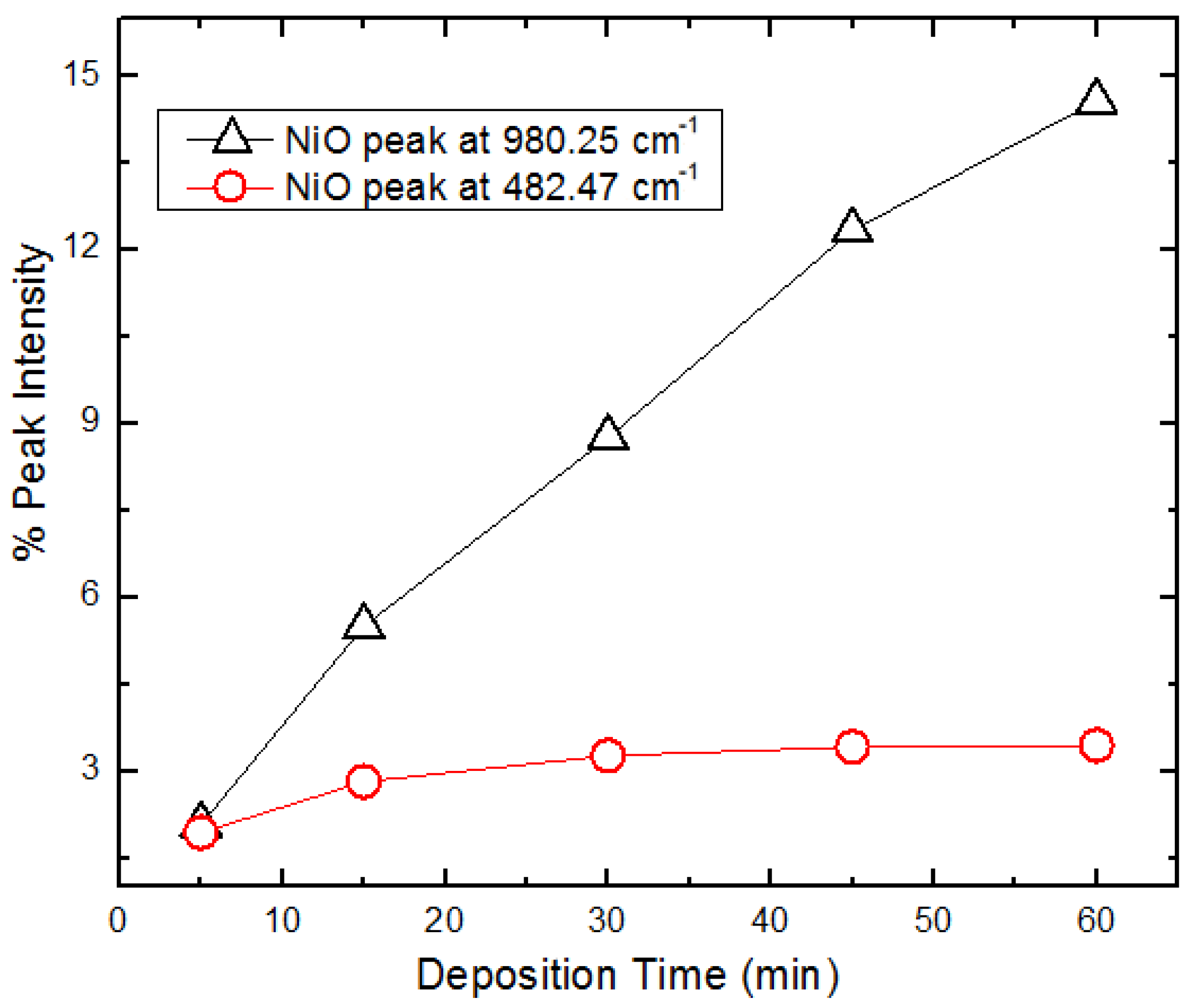
Figure 8.
SEM images of NiO particles deposited after (a) 5 and (b) 60 min at 250 mA/cm−2.

Figure 9.
Nyquist plot for NiO-GR/PI composites at different deposition times and current density (25 (a) and 250 mA/cm2 (b)); (c) equivalent electrical circuit model.
Figure 9.
Nyquist plot for NiO-GR/PI composites at different deposition times and current density (25 (a) and 250 mA/cm2 (b)); (c) equivalent electrical circuit model.
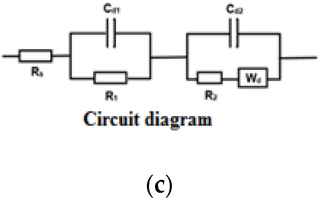
Figure 10.
Bulk resistance of NiO-GR/PI samples at different deposition times.

Figure 11.
CV curves for NiO-GR/PI samples electrodeposited at (a) 25 and (b) 250 mA/cm2 current densities at 5 to 60-min deposition times.
Figure 11.
CV curves for NiO-GR/PI samples electrodeposited at (a) 25 and (b) 250 mA/cm2 current densities at 5 to 60-min deposition times.


Figure 12.
Specific capacitance plot for NiO-GR/PI samples at different deposition times.

Figure 13.
Electrochemical performance comparisons of neat and hybrid GR/PI composite.


Table 1.
Summary table of bulk resistances.
| Composite | Specific Capacitance (F/g) | Bulk Resistance (ohm) |
|---|---|---|
| GR/PI | 49.13 | 434.50 |
| Modified porous GR/PI | 170.50 | 11.71 |
Publisher’s Note: MDPI stays neutral with regard to jurisdictional claims in published maps and institutional affiliations. |
© 2021 by the authors. Licensee MDPI, Basel, Switzerland. This article is an open access article distributed under the terms and conditions of the Creative Commons Attribution (CC BY) license (http://creativecommons.org/licenses/by/4.0/).
Share and Cite
MDPI and ACS Style
Okafor, P.; Iroh, J. Electrochemical Properties of Porous Graphene/Polyimide-Nickel Oxide Hybrid Composite Electrode Material. Energies 2021, 14, 582. https://doi.org/10.3390/en14030582
AMA Style
Okafor P, Iroh J. Electrochemical Properties of Porous Graphene/Polyimide-Nickel Oxide Hybrid Composite Electrode Material. Energies. 2021; 14(3):582. https://doi.org/10.3390/en14030582
Chicago/Turabian StyleOkafor, Patricia, and Jude Iroh. 2021. "Electrochemical Properties of Porous Graphene/Polyimide-Nickel Oxide Hybrid Composite Electrode Material" Energies 14, no. 3: 582. https://doi.org/10.3390/en14030582
Note that from the first issue of 2016, this journal uses article numbers instead of page numbers. See further details here.