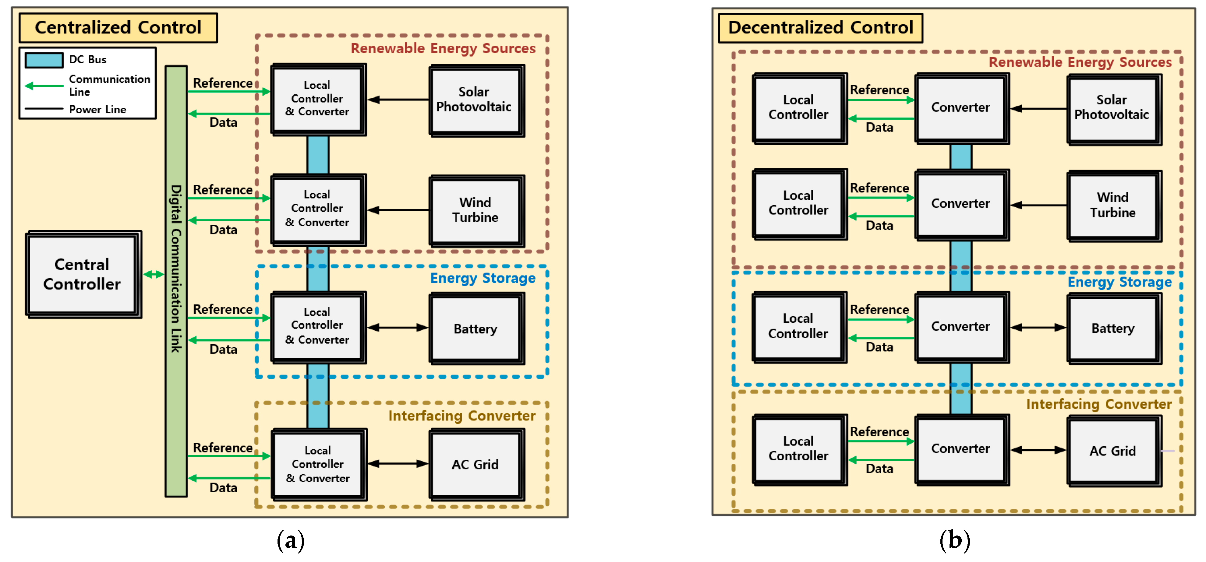
Article

Energy Management System of DC Microgrid in Grid-Connected and Stand-Alone Modes: Control, Operation and Experimental Validation

1
Department of Electrical and Computer Engineering, Sungkyunkwan University, Suwon 16419, Korea
2
Hanwah Defense Inc., Seongnam 13488, Korea
*
Author to whom correspondence should be addressed.
Energies 2021, 14(3), 581; https://doi.org/10.3390/en14030581
Submission received: 22 December 2020 / Revised: 14 January 2021 / Accepted: 20 January 2021 / Published: 23 January 2021
(This article belongs to the Special Issue Energy Conversion and Operation Technologies for Smart Grid)

Abstract

:
This paper proposes an energy management system (EMS) of direct current (DC) microgrid. In order to implement the proposed EMS, the control and operation method of EMS is presented in this work. While most of the studies have individually examined the grid-connected mode used in building and the stand-alone operation mode applicable to the island, the proposed EMS allows it to be used in both grid-connected mode and stand-alone mode with 10 modes. In order to determine each mode in EMS, not only the amount of generated power, load power, and the state of charge (SOC) of the battery, but also the rated power of the energy storage system (ESS) converter that performs charging and discharging operations is additionally considered. Thus, various uncertainties that may occur in the actual DC microgrid environment can be improved. A laboratory-scale DC microgrid is fabricated to conduct experimental validation of proposed EMS. Experiments of DC microgrid with proposed EMS were performed for each mode, and the experiment waveforms of each power conversion device are included in detail.

Graphical Abstract

1. Introduction

In today’s modern society, various types of loads increase exponentially, and the expansion of power generation, transmission and system facilities are required every year. However, as a global energy issue, a new paradigm is shifting from two perspectives. The first is to develop and expand alternative energy based on renewable energy sources (RESs) such as wind and solar energy. Another is a study on direct current (DC) microgrid that can improve distribution efficiency by reducing power conversion stages along with designing a high-efficiency power conversion device to cope with the increasing demand for digital loads. For this reason, research on distributed energy resources (DERs) using eco-friendly energy and research on DC microgrids is increasing rapidly around the world.
DC Microgrid using low voltage direct current (LVDC) generally has a voltage range of up to 1500 Vdc and is for distribution networks used in daily life, such as light emitting diode (LED), office-based electronic devices, and battery charging stations [1,2]. In such a DC microgrid, various distributed energy resources (DERs) are applied, and these are used in connection with RESs, which are recently spotlighted as distributed generation (DG). In this case, since intermittent power generation occurs, uncertainty of power supply in the DC microgrid occurs [3]. In addition, since the load in the DC microgrid is instantaneously variable, severe fluctuations in the power and voltage of the DC microgrid are also inevitable. In order to improve this, an energy management system (EMS) was required to apply the energy storage system (ESS) to DC microgrid for smart and stable operation.
For the control structure of the EMS to control DC microgrid, there exist decentralized control and centralized control methods [4]. These Centralized and Decentralized control structures are shown in Figure 1. In the case of centralized control, there is a central controller, and based on the digital communication line (DCL), it transmits a reference to control the power conversion device in the DC microgrid and communicates to receive data signals for monitoring. This has the advantage of high reliability, but requires cost and complexity to build DCL [5,6,7]. In the decentralized control scheme, since DCL does not exist, it is independent from complex communication technologies. Therefore, a communication noise problem can be avoided [8,9,10]. The decentralized control method is typically performed based on the droop control method [11]. The local controller controls the converter by itself, but at this time, there is a limitation of the control performance because information of other power conversion devices cannot be obtained.
The EMS transmits reference signal for instantaneous operation with power conversion devices in the DC microgrid. EMS is generally composed of a hierarchical control structure belonging to the centralized control method [12]. Many studies have been conducted based on this hierarchical control structure [13,14,15]. There are three control layers in the hierarchical control structure, which are divided into tertiary control, secondary control, and primary control. Through this EMS structure, it is possible to operate by monitoring and controlling the status of the DC microgrid in consideration of the power generation of DERs. The reliability and stability of the DC microgrid can be improved with this EMS structure.
These EMSs were studied for various purposes, depending on the location, size, and application of the system [16,17,18]. Camps built in military units or rural areas have offered hybrid energy systems to replace fuel supplies from diesel engine power generation, but lacked explanation for the operation method [19]. In order to implement EMS, a study using linear programming and rule-based control was carried out in DC microgrid and EV applications [20,21]. It is possible to operate in consideration of the utility cost of DC microgrid through linear programming applied as a mathematical optimalization method. In addition, rule-based control is operated by applying predefined rules for operation. Moreover, there are 36 different modes of study for the operation of DC microgrids, but the state of charge (SOC) of batteries is not considered and mode implementation is complex [22]. In addition, there is a study on the centralized control strategy of the laboratory scale for microgrid, but it is necessary to deal with details on how to control and operate the system [23].
However, the limitations of most studies on DC microgrid and EMS are as follows: (1) there is a lack of explanation of individual power conversion devices and control methods for integrated operation of DC microgrid. (2) The implementation of EMS is complicated by using too many modes with complex theories, or the contents of the operation method of EMS are simplified. (3) The laboratory scale of DC microgrid is difficult to implement, so there is a tendency to include only simulation results and there is a lack of research integrating actual experiment cases. (4) It contains only the contents of grid-connected systems, such as buildings, or only the stand-alone mode used in remote areas. This paper proposes an EMS based on power electronics and power system area for operating smart DC microgrid. It includes the integrated control and operation of each power conversion devices such as photovoltaic (PV) converter, wind turbine (WT) converter and ESS. Proposed EMS consider both grid-connected and stand-alone situations. Furthermore, it is described as determining the amount of charge and discharge power by considering the rated power and SOC of ESS through the EMS under distributed power generation and load power variation. To verify the feasibility and stability of the proposed EMS, the DC microgrid of the laboratory scale was built and verified by experiment.

2. Control and Operation Method of Proposed Energy Management System for DC Microgrid

This section describes the control and operation method of proposed EMS. This research try to use master controller of multi-level inverter (MLI) without using additional controllers in order to implement centralized control. To implement these central controls, they are divided into hierarchical control structures. It consists of a master controller and local controllers used for each power conversion system, where the reference signal required to be performed by each local controller and the information to be sent to the master controller differ from each other. Figure 2. shows the configuration of DC microgrid with EMS.
To operate DC microgrid, AC power is supplied through conventional AC grid. At this time, the DC bus is connected with AC grid after converting AC power to DC power using the interfacing converter (IFC). This method is used in grid-connected mode where the AC grid and IFC is maintained stably [24]. In grid-connected mode, the DC microgrid can receive the required power from the AC grid. In addition, bi-directional power control will be possible using surplus power to regenerate to the AC grid or to perform reactive power compensation. On the other hand, if an accident occurs on the AC grid or the power supply is cut off from the utility operator, it will operate in a stand-alone operation mode and control the DC bus voltage based on the WT converter. To construct laboratory scale DC microgrid similar to actual system, the WT system is composed as follows. The motor generator (MG) set was constructed using the permanent magnet synchronic generator (PMSG) and DC motor. MG set is used as a source for power control of WT converter [25].

2.1. Control Method of Proposed Energy Management System for DC Microgrid

This subsection covers the control method of each power conversion devices for the proposed EMS. Figure 3 shows the control block diagram of power conversion devices with proposed EMS.
This shows how the input and output signals through the proposed EMS are related to each power conversion devices of DERs. The hierarchical control structure used in this paper is divided into three layers. The master controller of the multi-level inverter is a tertiary controller that continuously receives power and status information from each local controller to manage the power flow of DC microgrid. At this point, the reference signal is transmitted to the local controller after determining the reference power value and mode that each DERs should be responsible for. In addition, the DC bus voltage is continuously monitored, and reference for maintaining the voltage are also calculated and sent to the secondary controller. Since the IFC and WT converter control the DC bus voltage, the controller used in these power conversion devices acts as a secondary controller.
The secondary controller continuously receives reference DC bus voltage signal from the tertiary controller, and performs control for stable DC bus voltage. In addition, primary control, which is the lowest level control for the operation of the IFC, is performed as AC current control for DC bus voltage, power factor, and reactive power control. At this time, if the IFC is broken and the DC bus voltage cannot be maintained, the tertiary controller sends an instruction to perform this secondary control by the WT converter rather than the IFC. As a result, in the event of failure of the IFC, the WT converter not only controls DC bus voltage, but also performs the secondary and primary control simultaneously to maintain the DC bus voltage. The controller used for the PV converter is the primary controller, which controls the voltage and current with perturbation & observation based maximum power point tracking algorithm [26]. The controller used in the ESS converter is also a primary controller that determines the charge and discharge by the power and currents determined by the tertiary controller, based on which the control to charge or discharge the battery is carried out.
As a result, the DC microgrid can be controlled through the control method of the power conversion devices of each DERs. In order to implement this control and operation of DC microgrid, it requires the EMS to determine the reference values according to the generated power, load power and SOC of battery, and so on.

2.2. Operation Method of Proposed Energy Management System for DC Microgrid

This subsection deals with the operation methods for determining the the mode and reference signal values according to the generated and load power of various DERs and SOC. Figure 4 shows flowchart for proposed EMS of the DC microgrid.
In order to operate EMS using the master controller of a multi-level inverter, there is a part that stores basic information of the power conversion devices that make up DC microgrid. Then there is the temporary storage portion of information and instantaneous power received. Information from the components that make up DC microgrid can be divided into rated power and SOC of battery SOCbat. The rated power of a multi-level inverter PMLI_rated is 10 [kW], the rated power of a PV converter PPV_rated is 1.8 [kW], the rated power of an ESS converter PBAT_rated is 5 [kW], and the rated power of a WT converter PWT_rated is 13.3 [kW], and the rated power of a DERs that make up a DC microgrid is controlled by the master controller. In addition, to prevent overcharging and over-discharge of batteries, the maximum SOC and the lowest SOC were defined as SOCbat_max and SOCbat_min, as 90 [%] and 20 [%], respectively.
The information received by each power conversion device is the amount of output power of DERs. The output power of PV converter PPV, WT converter PWT and battery charge/discharge of ESS PBAT will be received as the master controller from each local controller. In addition, SOCbat is received from the ESS converter which is calculated by coulomb counting method [27]. Depending on the failure of the interfacing converter or AC system, a StateGrid signal is received to distinguish grid-connected from stand-alone mode to determine the fault condition.
In order to control the power flow of DC microgrid, the generated power and load power of the DERs must be calculated. Based on the output power of PV converter PPV and output power of WT converter PWT, the generated power PDG and load power PLoad are calculated as below.
P D G = P P V + P W T P L o a d = P M L I + P D C L
where, PMLI is output power of multi level inverter and PDCL is output power of DC load. After receiving the information and instantaneous power of each power conversion device, it is classified as grid-connected mode for StateGrid = 1 and stand-alone mode for StateGrid = 0. Figure 5 shows the flowchart of proposed energy management system for operation method in grid-connected mode.
When operating in grid-connected mode, the amount of generated power of DERs PDG in the DC microgrid is firstly compared to the amount of load power PLoad. If the amount of generated power is greater than the load power (PDG > PLoad) is classified into the charging mode (Mode 1) or export power mode (Mode 2, 3), which is determined by the SOCbat, amount of charging power (PDGPLoad) and rated power of ESS converter PBAT_rated.

2.2.1. Grid-Connected Mode

If the SOCbat, becomes smaller than the maximum SOC limitations of the battery, the EMS will determine that the battery is capable of charging, so the battery charging mode (mode 1) is executable. The charging power is then determined by comparing the surplus power (PDGPLoad) to the rated power of the ESS converter PBAT_rated. If the surplus power is less than or equal to PBAT_rated (PDGPLoadPBAT_rated), the ESS converter performs charging operation as much as amount of the reference power of ESS P*BAT. P*BAT is calculated as Equation (2).
P B a t = P D G P L o a d = ( P P V + P W T ) P L o a d > 0
In the event of surplus power above PBAT_rated (PDGPLoad > PBAT_rated), the battery must be limited in charge, so it must be operated in charging and export mode (mode 2) which regenerates surplus power to the AC grid with battery charging. At this time, the P*BAT is the determined as Equation (3).
P B a t = P B a t _ r a t e d
In this case, surplus power is generated, and since the interfacing converter performs DC bus voltage control, the power corresponding to Equation (4) is regenerated to the AC system.
P I F C = P D G P L o a d P B a t _ r a t e d > 0
If the SOCbat is larger than SOCbat_max, the battery cannot be charged any more for avoiding overcharging. Therefore, export power mode (mode 3) is selected in order to regenerate the surplus power to the AC grid. In this case, the ESS converter does not perform the charging and discharging operation, and the power of Equation (5) is regenerated to the AC system through the DC bus voltage control of the interfacing converter.
P I F C = P D G P L o a d > 0
As a result, when the PDG of the DERs is higher than the load power PLoad in the grid connection mode, EMS determined the mode among the battery charging mode (mode 1), the charging & Export power mode (mode 2) and export power mode (mode 3). The EMS determines the mode and transmits the corresponding reference power, and the EMS keeps sending the reference power until the next information is received.
On the other hand, there is a case in which the load power PLoad is higher than the generated power PDG due to the intermittent output of the DERs in the grid connection mode. In this case, the SOCbat and SOCbat_min are compared to determine whether the battery can perform the discharge operation. If the value of SOCbat is higher than SOCbat_min, the discharge operation can be performed. Next, it is compared as to whether the value of required power for discharge is greater than or equal to the negative rated capacity PBAT_rated of the ESS converter. The required amount of power supply can be calculated by subtracting PLoad from the PDG. In this case, since the amount of load power is higher, the amount of surplus power has a negative value. In other word, insufficient power is generated. When this is compared with −PBAT_rated and the value is larger, the operation is performed as a battery discharge mode (mode 4) in which all the amount of power supplied through the battery can be supplied.
P B a t = P D G P L o a d = ( P P V + P W T ) P L o a d < 0
However, if the power supply is required with a negative value smaller than the rated capacity that the ESS converter can discharge −PBAT_rated, it operates in the battery discharge and import power mode (mode 5) where the discharge amount is limited as shown in Equation (7).
P B a t = P B a t _ r a t e d
The additionally required amount of power is imported from the AC grid, and the required power is as shown in the following Equation (8), and the intefacing converter imports power from the AC grid while performing DC bus voltage control.
P I F C = P D G P L o a d P B a t _ r a t e d < 0
If SOCbat is smaller than SOCbat_min, the battery cannot be discharged any longer, and thus the operation is performed as an import power mode (Mode 6). In this case, the ESS converter does not perform the charging and discharging operation, and the power of Equation (5) is imported from the AC grid through the DC bus voltage control of the intefacing converter.
P I F C = P D G P L o a d < 0
Therefore, when the generated power PDG is less than the load power PLoad in the grid connection mode, ESS takes the discharge mode of the battery or an Import power mode. According to the rated capacity of the ESS converter, EMS determines the battery discharge mode (mode 4), discharge and import power mode (mode 5), and import power mode (mode 6) to operate the DC microgrid.

2.2.2. Stand-Alone Mode

Interfacing converters generally perform DC bus voltage control. If DC microgrid disconnects from the AC grid due to a grid accident, the grid connection mode cannot be maintained anymore. In this case, the grid-connected can no longer be performed by the method of detecting overvoltage and overcurrent of the AC grid among the internal slave control of the intefacing converter. The grid-connected operation is stopped to protect the DC microgrid, and a signal of StateGrid = 0 is generated to deliver the information to EMS. Through this, EMS determines the operation as a stand-alone mode, and performs the operation algorithm of the DC microgrid in the stand-alone operation mode as shown in Figure 6.
When the stand-alone mode is determined, the generated power PDG and the load power PLoad are compared as in the grid connection mode. When the generated power PDG becomes larger than the load power PLoad, the battery operates in the charging mode (mode 7). In the case of the battery charging mode in mode 7, it is the same as in the grid-connected mode. In case of stand-alone mode, when PLoad is higher than the PDG, EMS determines among the battery discharge mode (mode 8) or discharging & load constraint mode (mode 9) or load constraint mode (mode 10).
In the case of the battery discharging mode (mode 8), the mode 8 occurs under the same conditions as the grid-connection mode (mode 1). When the amount of required power by the load in the DC microgrid exceeds the rated capacity −PBAT_rated, the discharge power of the battery is limited as −PBAT_rated. The additionally required load power is operated in discharge & load constraint mode (Mode 9), which is limited as shown in the following Equation (10).
P B a t = P B a t _ r a t e d P L o a d _ lim i t = ( P D G P L o a d + P B a t _ r a t e d )
where, P*Load_limit is the limited load power reference of the multi-level inverter, by checking the load power PLoad from the master controller instantaneously and reducing the speed reference value in a ramp form to limit it as the limited load power reference P*Load_limit. As the power amount PLoad is limited and some amount of power is regenerated from the AC load, it operates as a constraint mode that can prevent a sudden drop in voltage at the DC bus side.
However, when the amount of load power is larger than the amount of generated power, if the SOC of the battery SOCbat becomes smaller than the SOCbat_min, the discharge operation cannot be performed anymore and the load power cannot be supplied anymore. In order to prevent a voltage drop at the DC bus side, it operates in a load constraint mode (mode 10) in which the output power of the load is controlled to zero and the operation is stopped.
In this stand-alone operation mode, since DC microgrid is not connected to the AC grid, it is not possible to receive power from the AC grid to supply load power when the ESS can not discharge anymore. In order to operate DC microgrid in stand-alone mode, proposed EMS determines the mode to control ESS operation and the amount of load power in stand-alone mode. It is possible to perform stable operation of the DC microgrid under generated power and load variation with operation method of EMS.

3. Experiment Results

In order to confirm the validity of the proposed EMS, experiments were conducted on DERs, multilevel inverters and energy storage system. Figure 7 shows the configuration diagram of the entire experimental system to verify the proposed energy management system.
The configuration of each power conversion device for experimental set is as follows. First, Figure 8 is an experimental configuration of an interfacing converter. It consists of two 3-phase AC/DC PWM converters. There is a magnetic contactor (MC) and a control relay for the electrical connection and isolation between the AC grid and DC bus. In addition, there is an LCL filter to improve the power quality of the AC grid.
Figure 9a shows the experimental configuration of an ESS converter. Battery is made to form 240 V by connecting 12 V in series of 20 EA. Figure 10b shows the composition of a wind turbine system. Here, a 13.3 kW PMSG-based MG set was used. It also shows a WT converter.
Figure 10a shows the experimental configuration of a PV converter. It shows that the voltage and current sensors of the PV input side are added to control the PV converter with MPPT. Figure 10b shows a multi-level inverter. It is composed of 9 power modules and a resistive load is used as the AC load.
To confirm the validity of the proposed EMS, the generated power and load power profile of the DC microgrid was simulated for each mode and stable operation is verified in each mode. The experiment was conducted by dividing into grid-connection mode and stand-alone mode.

3.1. Grid-Connected Mode

Figure 11, Figure 12 and Figure 13 show the experimental waveform in the mode 1. At this time, the output power of each power conversion device is shown in Table 1. In the First period I, the interfacing converter that controls the DC bus voltage was operated and the DC load was connected. At this time, 3.4 kW of DC load power was consumed, and the generated power was changed by controlling the reverse torque reference of the WT converter. When the reverse torque reference becomes −332 Nm, wind power generates about 6.6 kW in period II. Therefore, when the reverse torque reference reaches −332 Nm, the multilevel inverter using 5 kW of load power and the PV converter generates 1.8 kW.
At this period II, the total generated power of the DERs is about 8.4 kW and the load power is also about 8.4 kW, so no power is supplied from the AC grid. In the period III, if the reverse torque reference is changed to −382 Nm, the surplus power becomes 1 kW, and the EMS of the multilevel inverter master controller transmits the reference power to the ESS converter, thereby surplus generated power is charged by ESS converter as shown in Figure 13. Therefore, the DERs is responsible for all the power used by the load. Since the surplus generated power does not exceed the rated power of ESS converter, all of the surplus generated power is charged to the ESS in mode 1.
Figure 14, Figure 15, Figure 16 and Figure 17 shows the experimental waveform in operation mode 2. At this time, the output power of each power conversion device is shown in Table 2. As in the previous operation mode 1, when 6.6 kW of power is generated by changing the reverse torque reference of the WT converter to −332 Nm, the PV converter generates 1.8 kW power as shown in Figure 17. In this period II, the ESS converter charges 5 kW. After that, if the reverse torque reference is changed to −382 Nm again, the WT converter generates 7.6 kW power, 1 kW of surplus power is exported to AC grid in period III.
As a result, if the load is less than the generated power and the surplus power is larger than the rated power of the ESS, 1 kW remained power is regenerated to AC grid in mode 2.
Figure 18, Figure 19, Figure 20 and Figure 21 shows the experimental waveform in mode 3 situation. At this time, the output power of each power conversion device is shown in Table 3. The mode 3 is the same as the previous operation modes until the 6.6 kW power generation of WT power generation in the period II. At this time, when the EMS receives that the SOC of the ESS exceeds SOCbat_max, it commands the ESS not to charge excess power anymore. Therefore, if the reverse torque reference of the WT converter is changed to −433 Nm, the generated power of the WT power generation becomes 8.6 kW. The remained power 2 kW is regenerated to the AC grid in the period III.
Figure 22, Figure 23, Figure 24 and Figure 25 shows the experimental waveform in mode 4. The output power of each power conversion device is shown in Table 4. In the period II, WT converter generates 6.6 kW and multi-level inverter and DC load power are 5 kW and 3.4 kW respectively. PV converter generates 1.8 kW. If the reverse torque reference of WT converter is changed to −282 Nm and the power generation is lowered to 5.6 kW in period III, EMS confirms that the SOC is greater than SOCbat_min, and then the insufficient power is provided by the ESS converter. Therefore, ESS converter discharges when the generated power decreases due to the change of the reverse torque reference of WT converter as shown in Figure 25.
Figure 26, Figure 27, Figure 28 and Figure 29 shows the experimental waveform in mode 5. The output power of each power conversion device is shown in Table 5. In the period I of mode 5, WT converter generates 6.6 kW and multi-level inverter and DC load power are 5 kW and 3.4 kW respectively. PV converter generates 1.8 kW. In the period II, if the reverse torque reference of WT converter is changed to −282 Nm and the power generation is lowered to 5.6 kW, EMS determines the discharging power reference as much as −1 kW. After that, the reverse torque reference of WT converter is changed to −80 Nm and the power generation power is lowered to 1.6 kW in the period III then generated power becomes the same as PBAT_rated, the rated power of ESS. In the period IV, if the load connected to the multi-level inverter is changed from 5 kW to 7.3 kW as shown in Figure 28, the amount of the load power becomes more than the maximum amount of generated power and ESS discharging power, so additionally required power is imported from the AC grid. Therefore, 2.3 kW of power flows into the DC microgrid.
Figure 30, Figure 31, Figure 32 and Figure 33 shows the experimental waveform in mode 6 situation. At this time, the output power of each power conversion device is shown in Table 6. In the period II of mode 6, the reverse torque reference of WT converter is given −332 Nm to generate 6.6 kW. At this time, the PV converter is generating 1.8 kW and multilevel inverter is consuming 5 kW. In the period 3, the DC load was changed from 3.4 kW to 6.8 kW as shown in Figure 32. At this time, if EMS checks that SOCbat is less than SOCbat_min, the ESS converter commands not to discharge anymore. Therefore, 3.4 kW of load power, which is less than the generated power, is imported from the AC grid system as shown in Figure 30 and Figure 31.

3.2. Stand-Alone Mode

When a problem occurs in the AC grid, the WT converter replaces the interfacing converter to perform secondary and primary control. In order to perform mode 7, the grid-connected mode is switched to the stand-alone mode. The mode 7 operates in grid-connected mode before switching to stand-alone mode. In this case, PV converter generates 1.8 kW power. The 6.8 kW for DC load and 5 kW for multi-level inverter is consuming respectively. Therefore, when 10 kW of power from the AC grid is flowing into the DC microgrid, a fault signal was given to the EMS as AC grid problem. Table 7 shows the output power of each power conversion devices in mode 7. In EMS, the magnetic contactor connecting the interfacing converter and the DC bus is opened, and at the same time, the WT converter is supervised to maintain the the DC bus voltage as shown in Figure 34.
In the period I, it is assumed that the interfacing converter is operating in grid-connected mode, and the AC grid is disconnected at the point 1 At this time, the StateGrid is changed to zero, and the WT converter performs DC bus voltage control for stand-alone mode operation. Interfacing converter stops operating at the same time. The MC #1 which is used to connect between the interfacing converter and DC bus is separated. At the point 2, the MC #3 on the AC grid side is separated. As a result, interfacing converter is completely disconnected from the DC microgrid. At the point 3, the MC #2 is turned on to discharge the remaining DC capacitor voltage of the interfacing converter.
After that, when the DC microgrid operates stably, the power consumed by the multilevel inverter is reduced from 5 kW to 4 kW as shown in Figure 35. Therefore, 1 kW of surplus power remains, so this power is charged to the ESS as shown in Figure 36. Through this, it was verified that the stand-alone mode switching and the operation of mode 7 were performed stably.
In mode 8, the experiment was conducted in a stand-alone mode in which WT converter maintains the DC bus voltage. Table 8 shows the output power of the power conversion device in mode 8. In Mode 8, WT converter and PV converter generating 0 kW and 1.8 kW respectively. The DC load power is 6.8 kW and the multi-level inverter power is 5 kW. At this time, if the output power of the multilevel inverter is changed to 6 kW as shown in Figure 37, the insufficient power of 1kW is commanded by EMS to supply from the ESS converter as shown in Figure 38.
In operation mode 9, the PV converter generates 1.8 kW and the ESS discharges 1.6 kW. At this time, 3.4 kW DC load is connected. Table 9 shows the output power of each power conversion device. If the DC load of 3.4 kW is changed to 6.8 kW, the ESS discharges the maximum rated power of 5kW as shown in Figure 39. After that, even if you try to use the load power additionally by operating the multilevel inverter, the EMS determines that there is no additional power because it already uses all the power of the generation and ESS, and sends reference to stop the operation of the multilevel inverter as shown in Figure 40. This load constraint mode can also cut off the load under the mode 10.
Through the experimental results in stand-alone mode, it was verified that DC microgrid is stably operated with proposed EMS under various generated power and load power. Since the AC grid is not connected with DC microgrid in the stand-alone mode, it is important to supply power to the load and perform stable operation using power conversion devices in the DC microgrid. Therefore, load constraint mode is required in stand-alone mode. In order to implement stand-alone mode operation in the actual DC microgrid, it is considered that the type of load is classified into critical loads and non-critical loads. As a results, it was verified that the proposed EMS operates stably in experiment results when the various situations that can be occurred in both grid-connected mode and stand-alone mode depending on the amount of generated power, load power, and SOC.

4. Conclusions

In this paper, EMS for DC microgrid was proposed. In order to implement the proposed EMS, each power conversion device and control method is defined and described. The reference signals controlled by each power conversion device are described through the operation method of the proposed EMS. The operation method of the EMS determines modes and reference power of ESS by considering the generated power, load power, SOC, and the rated capacity of the ESS. In order to verify the proposed EMS, laboratory scale DC microgrid for integrated operation of renewable energy sources such as PV and WT, ESS, multi-level inverter, and interfacing converters was fabricated and experiment is conducted. For experimental verification of proposed EMS, situation of each mode was implemented. Through this, it was verified through an experiment that the proposed EMS operates stably in each operation mode even if the generated power and load power is fluctuated. In addition, it can be confirmed that the operation of the proposed EMS is stably performed from the viewpoint of the both power system and power electronics. It is considered that many experiment waveforms in this research will be helpful in reader’s future work. This paper involves study with the following significance: (1) This study described combined with explanation of individual power conversion devices and control methods for integrated operation of DC microgrid. (2) The operation method of proposed EMS can be simply implemented comparing with conventional complex research. (3) The laboratory scale of DC microgrid is fabricated and proposed EMS is verified in actual experiment cases. (4) Proposed EMS contains both of grid-connected and stand-alone mode so that it is practical and feasible in real application of DC microgrid installed in building, island, rural area. This study was thanks to support from Korea institute of energy technology evaluation and planning (KETEP) for research and development of LVDC distribution system and DC microgrid. This was great help in fabricating a laboratory-scale DC microgrid and conducting this research. In the future, various ideas and activation of research about DC microgrid and EMS are expected based on the control and operation method of proposed EMS.

Author Contributions

H.L. and J.-W.K. conceived and designed the theory and experiment; H.L., B.-Y.C. and K.-M.K. performed the experiment; H.L. and J.-W.K. analyzed the theory. H.L. wrote the manuscript. M.-N.K. and C.-G.A. review the manuscript and search conventional studies. C.-Y.W. and J.Y. participated in research plan development and revised the manuscript. All authors have read and agreed to the published version of the manuscript.

Funding

This research received no external funding.

Institutional Review Board Statement

Not applicable.

Informed Consent Statement

Not applicable.

Data Availability Statement

Not applicable.

Acknowledgments

This work was supported by “Human Resources Program in Energy Technology” of the Korea Institute of Energy Technology Evaluation and Planning (KETEP), granted financial resource from the Ministry of Trade, Industry & Energy, Republic of Korea (No. 20184030202190). This work was supported by the Korea Institute of Energy Technology Evaluation and Planning (KETEP) and the Ministry of Trade, Industry & Energy (MOTIE) of the Republic of Korea (No. 2019381010001B).

Conflicts of Interest

The authors declare no conflict of interest.

References

  1. Dragicevic, T.; Lu, X.; Vasquez, J.C.; Guerrero, J.M. DC Microgrids—Part II: A Review of Power Architectures, Applications, and Standardization Issues. IEEE Trans. Power Electron. 2016, 31, 3528–3549. [Google Scholar] [CrossRef] [Green Version]
  2. Anand, S.; Fernandes, B.G.; Guerrero, J. Distributed Control to Ensure Proportional Load Sharing and Improve Voltage Regulation in Low-Voltage DC Microgrids. IEEE Trans. Power Electron. 2013, 28, 1900–1913. [Google Scholar] [CrossRef] [Green Version]
  3. Go, S.-I.; Choi, J.-H. Design and Dynamic Modelling of PV-Battery Hybrid Systems for Custom Electromagnetic Transient Simulation. Electronics 2020, 9, 1651. [Google Scholar] [CrossRef]
  4. Dragicevic, T.; Lu, X.; Vasquez, J.C.; Guerrero, J.M. DC Microgrids–Part I: A Review of Control Strategies and Stabilization Techniques. IEEE Trans. Power Electron. 2015, 31, 4876–4891. [Google Scholar] [CrossRef] [Green Version]
  5. Valenciaga, F.; Puleston, P. Supervisor Control for a Stand-Alone Hybrid Generation System Using Wind and Photovoltaic Energy. IEEE Trans. Energy Convers. 2005, 20, 398–405. [Google Scholar] [CrossRef]
  6. Salomonsson, D.; Soder, L.; Sannino, A. An adaptive control system for a DC microgrid for data centers. IEEE Trans. Ind. Appl. 2008, 44, 1910–1917. [Google Scholar] [CrossRef]
  7. Valenciaga, F.; Puleston, P.F. High-Order Sliding Control for a Wind Energy Conversion System Based on a Permanent Magnet Synchronous Generator. IEEE Trans. Energy Convers. 2008, 23, 860–867. [Google Scholar] [CrossRef]
  8. Boroyevich, D.; Cvetković, I.; Dong, D.; Burgos, R.; Wang, F.; Lee, F. Future electronic power distribution systems: A contemplative view. In Proceedings of the 2010 12th International Conference on Optimization of Electrical and Electronic Equipment, Basov, Romania, 20–22 May 2010; pp. 1369–1380. [Google Scholar]
  9. Gavriluta, C.; Candela, J.I.; Citro, C.; Rocabert, J.; Rodriguez, P. Decentralized Primary Control of MTDC Networks with Energy Storage and Distributed Generation. IEEE Trans. Ind. Appl. 2014, 50, 4122–4131. [Google Scholar] [CrossRef]
  10. Han, H.; Li, L.; Wang, L.; Su, M.; Zhao, Y.; Guerrero, J.M. A Novel Decentralized Economic Operation in Islanded AC Microgrids. Energies 2017, 10, 804. [Google Scholar] [CrossRef] [Green Version]
  11. Guerrero, J.M.; Vasquez, J.C.; Matas, J.; De Vicuna, L.G.; Castilla, M. Hierarchical Control of Droop-Controlled AC and DC Microgrids—A General Approach toward Standardization. IEEE Trans. Ind. Electron. 2011, 58, 158–172. [Google Scholar] [CrossRef]
  12. Che, L.; Shahidehpour, M. DC Microgrids: Economic Operation and Enhancement of Resilience by Hierarchical Control. IEEE Trans. Smart Grid 2014, 5, 2517–2526. [Google Scholar] [CrossRef]
  13. Bidram, A.; Davoudi, A. Hierarchical Structure of Microgrids Control System. IEEE Trans. Smart Grid 2012, 3, 1963–1976. [Google Scholar] [CrossRef]
  14. Dou, C.; Li, N.; Yue, D.; Liu, T. Hierarchical hybrid control strategy for micro-grid switching stabilisation during operating mode conversion. Gener. Transm. Distrib. IET 2016, 10, 2880–2890. [Google Scholar] [CrossRef]
  15. Mahmoud, M.S.; Rahman, M.S.U.; Al-Sunni, F.M. Review of microgrid architectures—A system of systems perspective. Renew. Power Gener. IET 2015, 9, 1064–1078. [Google Scholar] [CrossRef]
  16. Bunker, K.J.; Cook, M.D.; Weaver, W.W.; Parker, G.G. Multidimensional Optimal Droop Control for DC Microgrids in Military Applications. Appl. Sci. 2018, 8, 1966. [Google Scholar] [CrossRef] [Green Version]
  17. Gunasekaran, M.; Mohamed Ismail, H.; Chokkalingam, B.; Mihet-Popa, L.; Padmanaban, S. Energy Management Strategy for Rural Communities’ DC Micro Grid Power System Structure with Maximum Penetration of Renewable Energy Sources. Appl. Sci. 2018, 8, 585. [Google Scholar] [CrossRef] [Green Version]
  18. Ahmed, N.; Levorato, M.; Valentini, R.; Li, G.-P. Data Driven Optimization of Energy Management in Residential Buildings with Energy Harvesting and Storage. Energies 2020, 13, 2201. [Google Scholar] [CrossRef]
  19. Berardi, U.; Tomassoni, E.; Khaled, K. A Smart Hybrid Energy System Grid for Energy Efficiency in Remote Areas for the Army. Energies 2020, 13, 2279. [Google Scholar] [CrossRef]
  20. Ouédraogo, S.; Faggianelli, G.A.; Pigelet, G.; Duchaud, J.-L.; Notton, G. Application of Optimal Energy Management Strategies for a Building Powered by PV/Battery System in Corsica Island. Energies 2020, 13, 4510. [Google Scholar] [CrossRef]
  21. Corrêa, F.C.; Eckert, J.J.; Silva, L.C.; Martins, M.; Baroncini, V.; Santiciolli, F.M.; Gonçalves, C.; Dedini, G.F. Rule-based Control and Fuzzy Control for Power Management Strategies for Hybrid Vehicles. In Proceedings of the 2020 IEEE Colombian Conference on Applications of Computational Intelligence (IEEE ColCACI 2020), Cali, Colombia, 7–8 August 2020; pp. 1–6. [Google Scholar]
  22. Padilla-Medina, A.; Perez-Pinal, F.; Jimenez-Garibay, A.; Vazquez-Lopez, A.; Martinez-Nolasco, J. Design and Implementation of an Energy-Management System for a Grid-Connected Residential DC Microgrid. Energies 2020, 13, 4074. [Google Scholar] [CrossRef]
  23. Kermani, M.; Carnì, D.L.; Rotondo, S.; Paolillo, A.; Manzo, F.; Martirano, L. A Nearly Zero-Energy Microgrid Testbed Laboratory: Centralized Control Strategy Based on SCADA System. Energies 2020, 13, 2106. [Google Scholar] [CrossRef]
  24. Tran, T.T.; Nguyen, M.K.; Nguyen, H.N.; Duong, T.D.; Lim, Y.C.; Choi, J.H. A Three-Phase Constant Common-Mode Voltage Inverter with Triple Voltage Boost for Transformerless Photovoltaic System. IEEE Access 2020, 8, 166692–166702. [Google Scholar] [CrossRef]
  25. Lee, H.; Kang, J.W.; Choi, B.Y.; Kang, K.M.; An, C.G.; Won, C.Y. Operation and Control Strategy of Energy Management System for LVDC Distribution System. In Proceedings of the 2019 IEEE 4th International Future Energy Electronics Conference (IFEEC), Singapore, 25–28 November 2019; pp. 1–8. [Google Scholar]
  26. Debnath, A.; Olowu, T.O.; Parvez, I.; Dastgir, M.G.; Sarwat, A. A Novel Module Independent Straight Line-Based Fast Maximum Power Point Tracking Algorithm for Photovoltaic Systems. Energies 2020, 13, 3233. [Google Scholar] [CrossRef]
  27. Mian Qaisar, S. Event-Driven Coulomb Counting for Effective Online Approximation of Li-ion Battery State of Charge. Energies 2020, 13, 5600. [Google Scholar] [CrossRef]
Figure 1. Control structure of DC microgrid (a) centralized control, (b) decentralized control.
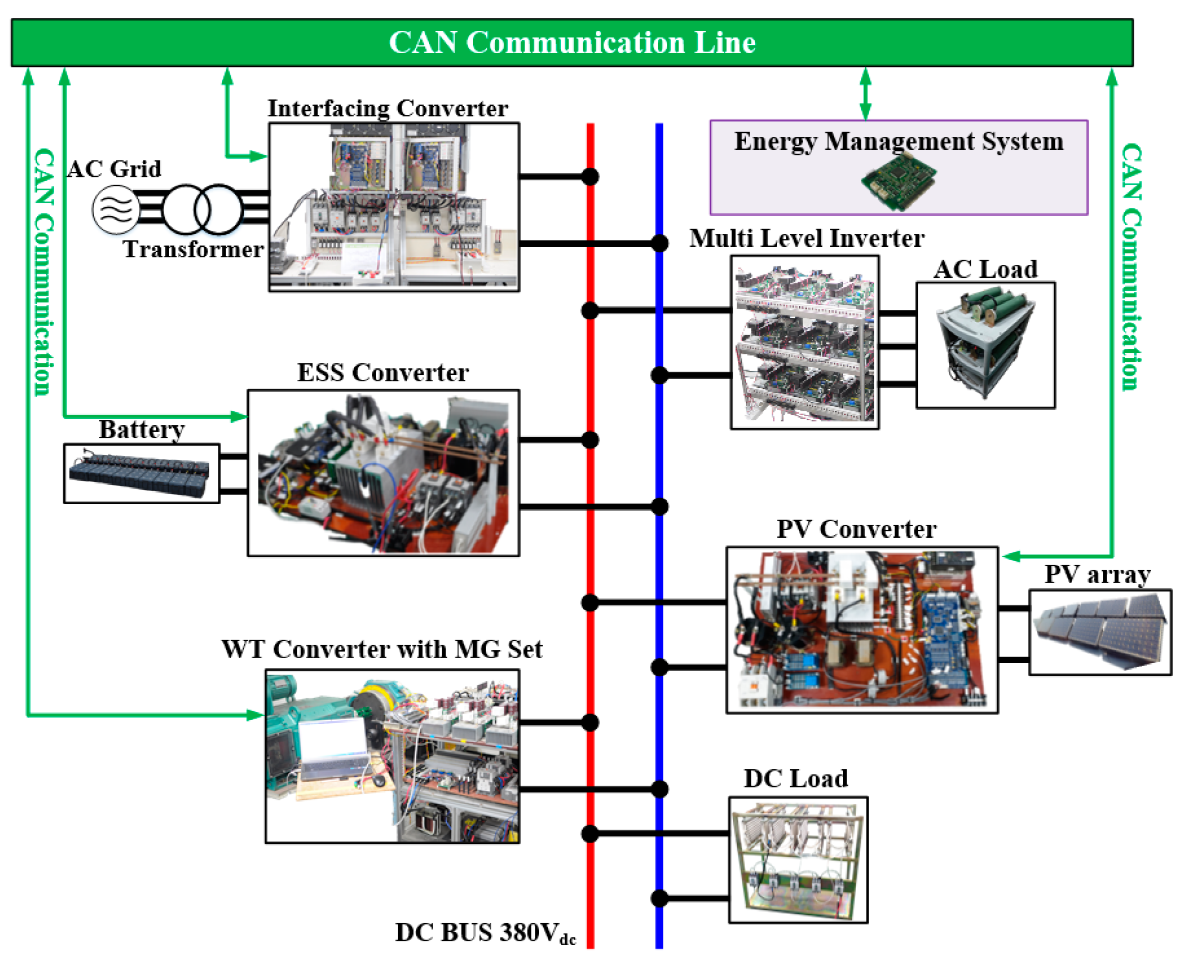
Energies 14 00581 g001
Figure 2. Configuration of DC microgrid with EMS.
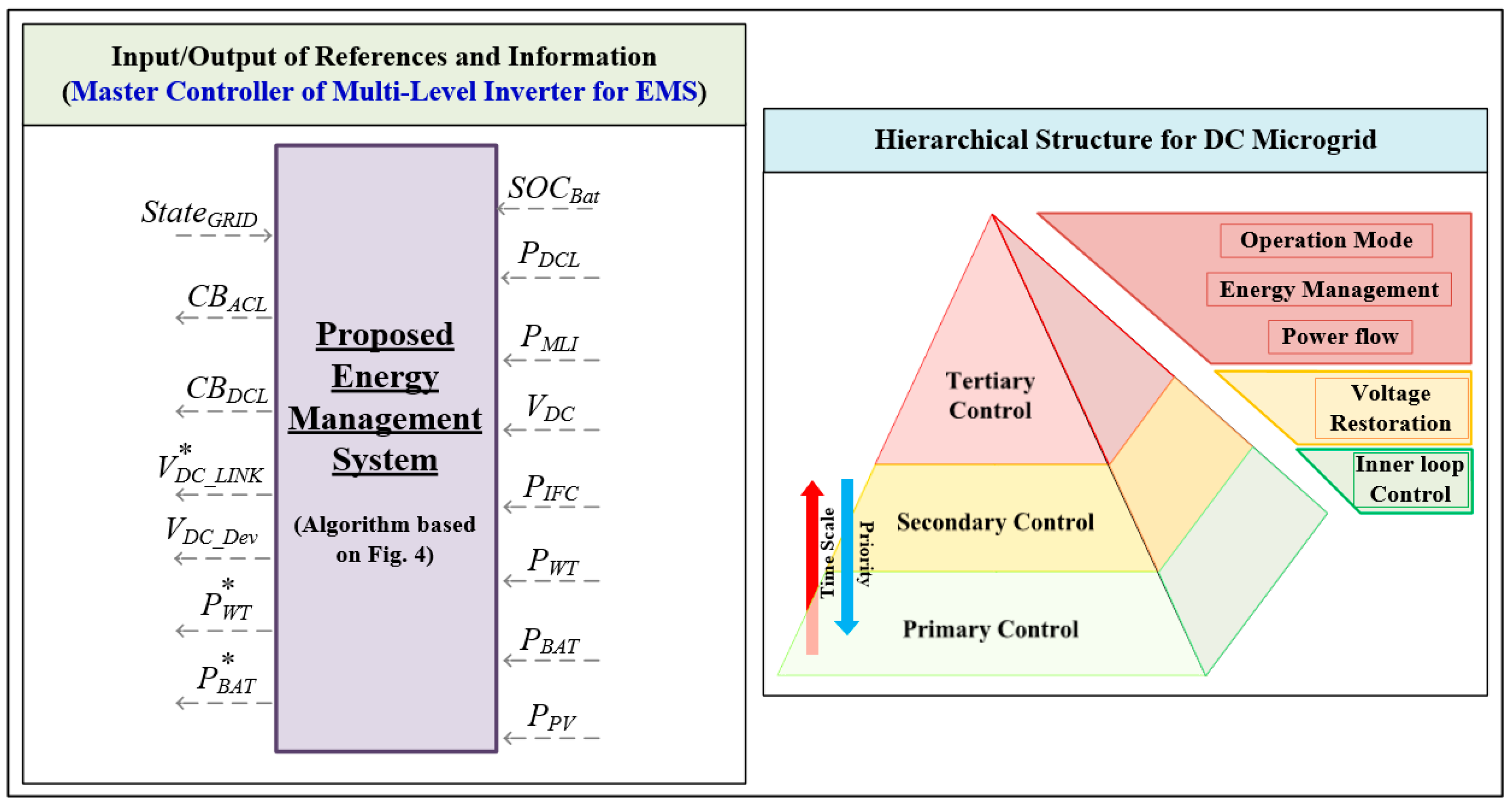
Energies 14 00581 g002
Figure 3. Control block diagram of power conversion devices with proposed EMS.
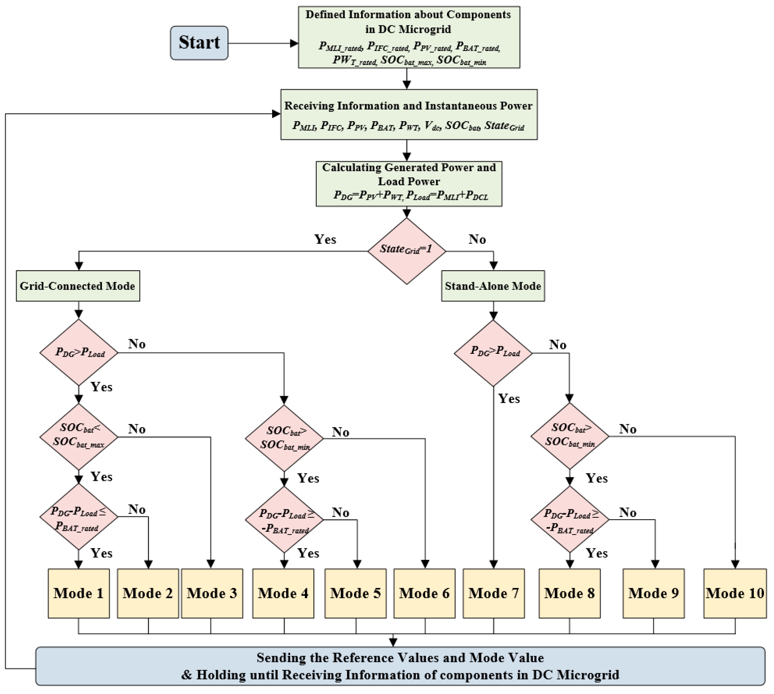
Energies 14 00581 g003aEnergies 14 00581 g003b
Figure 4. Flowchart of proposed EMS for operation method.
Energies 14 00581 g004
Figure 5. Flowchart of proposed EMS for operation method in grid-connected mode.
Energies 14 00581 g005
Figure 6. Flowchart of proposed EMS for operation method in stand-alone mode.
Energies 14 00581 g006
Figure 7. Experiment configuration of DC microgrid.
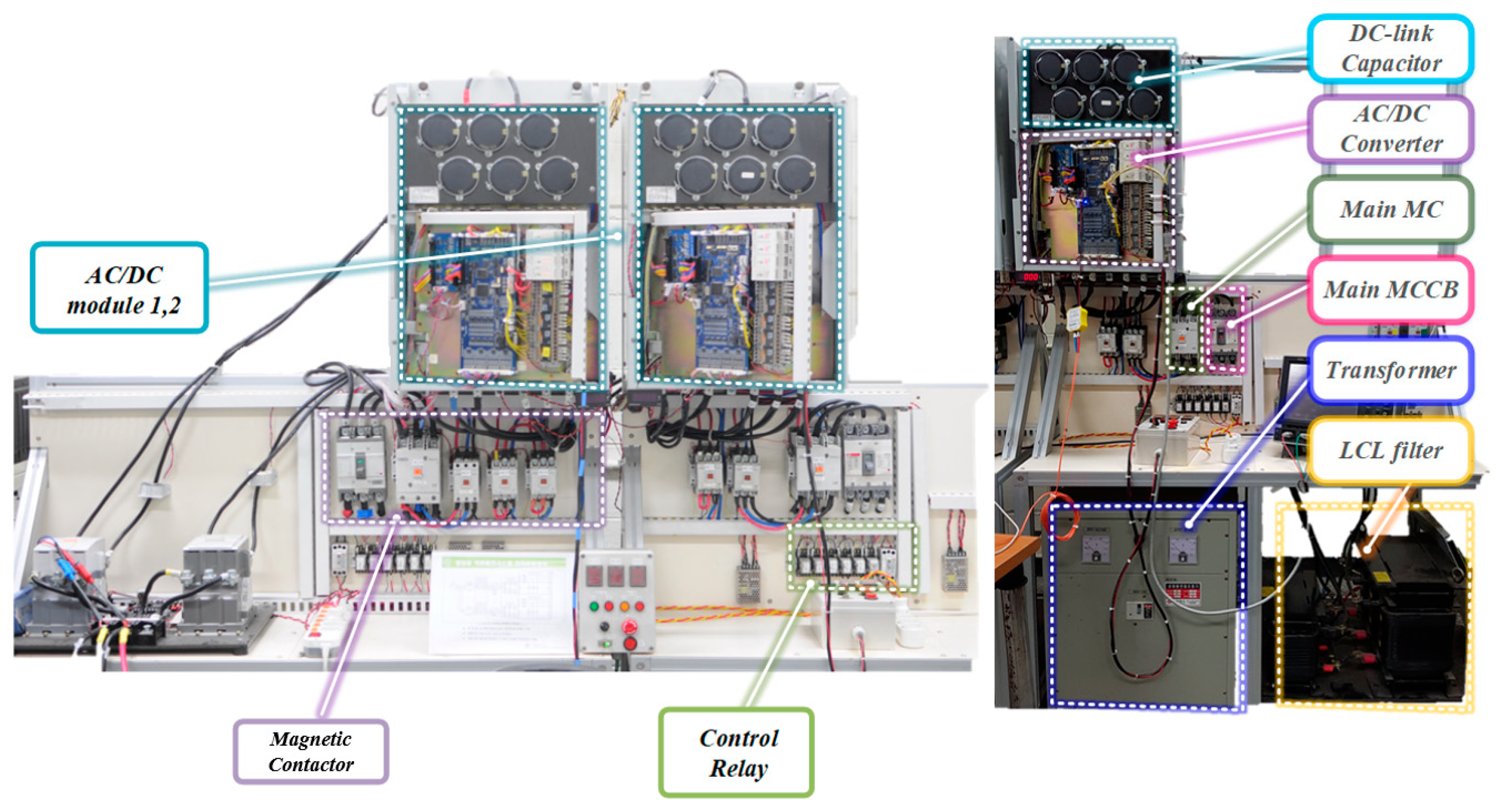
Energies 14 00581 g007
Figure 8. Experiment configuration of interfacing converter.
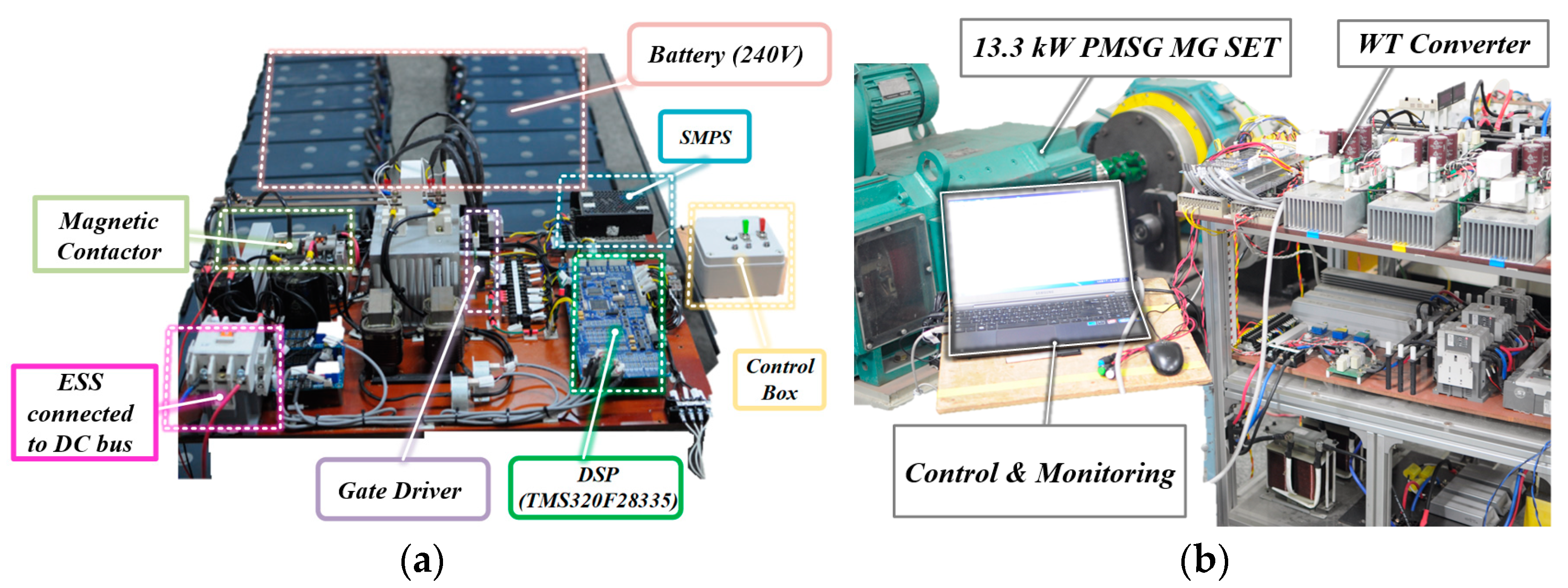
Energies 14 00581 g008
Figure 9. Experiment configuration of distributed energy resources (a) energy storage system, (b) wind turbine system.
Energies 14 00581 g009
Figure 10. Experiment configuration of power conversion devices (a) PV converter, (b) MLI.
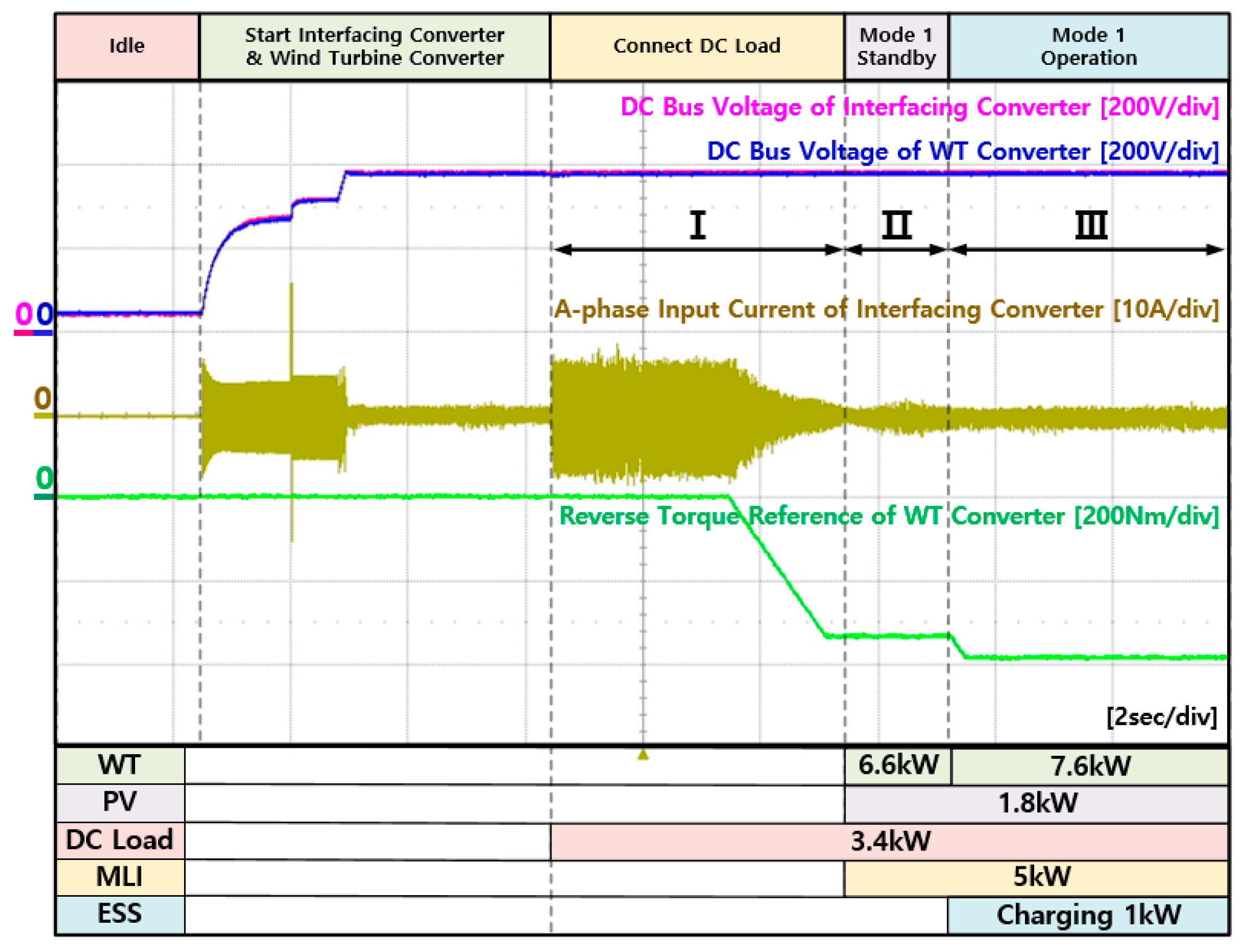
Energies 14 00581 g010
Figure 11. Experiment waveforms of interfacing converter and WT converter in mode 1.
Energies 14 00581 g011
Figure 12. Experiment waveforms of DC load and multi-level inverter in mode 1.
Energies 14 00581 g012
Figure 13. Experiment waveforms of PV converter and ESS converter in mode 1.
Energies 14 00581 g013
Figure 14. Experiment waveforms of interfacing converter and WT converter in mode 2.
Energies 14 00581 g014
Figure 15. Experiment waveforms of interfacing converter at AC grid in mode 2.
Energies 14 00581 g015
Figure 16. Experiment waveforms of DC load and multi-level inverter in mode 2.
Energies 14 00581 g016
Figure 17. Experiment waveforms of PV converter and ESS converter in mode 2.
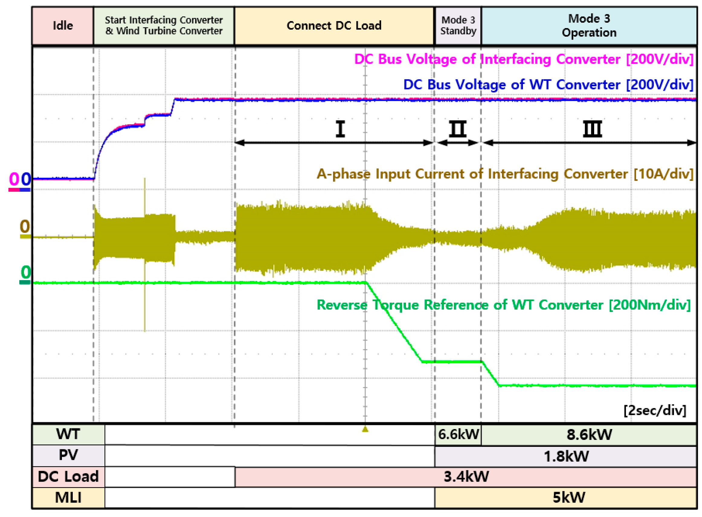
Energies 14 00581 g017
Figure 18. Experiment waveforms of interfacing converter and WT converter in mode 3.
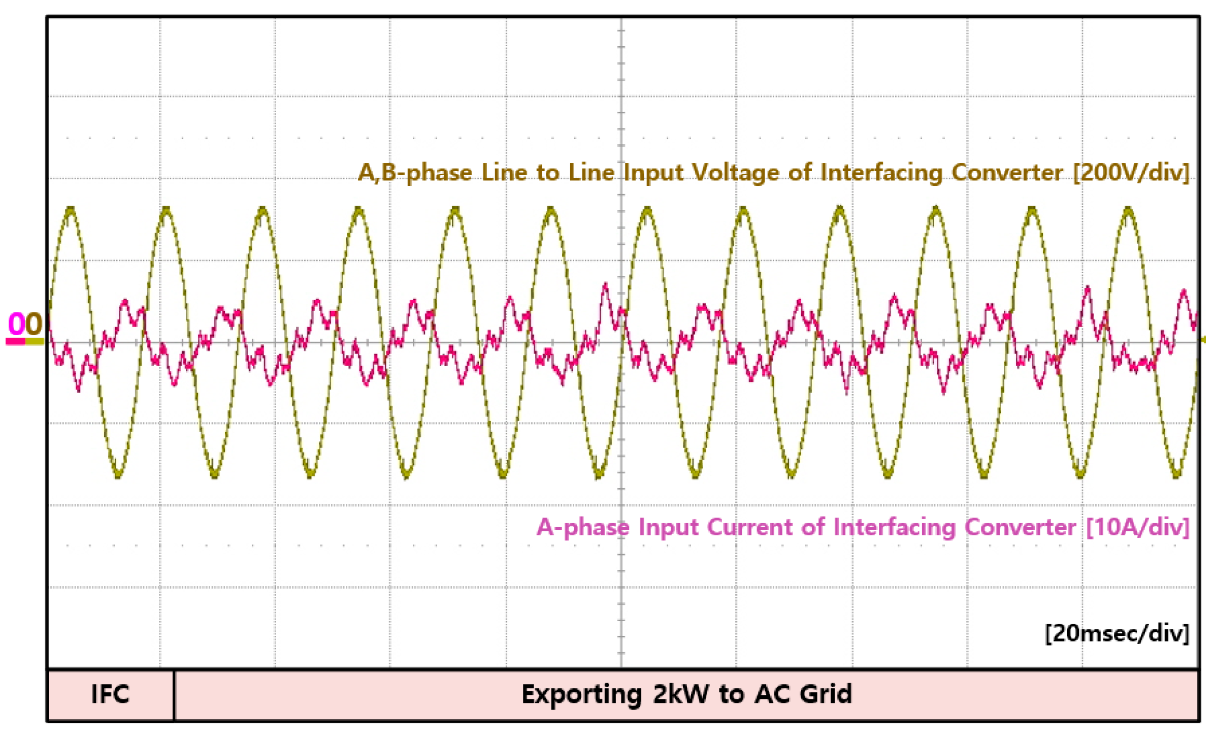
Energies 14 00581 g018
Figure 19. Experiment waveforms of interfacing converter at AC grid in mode 3.
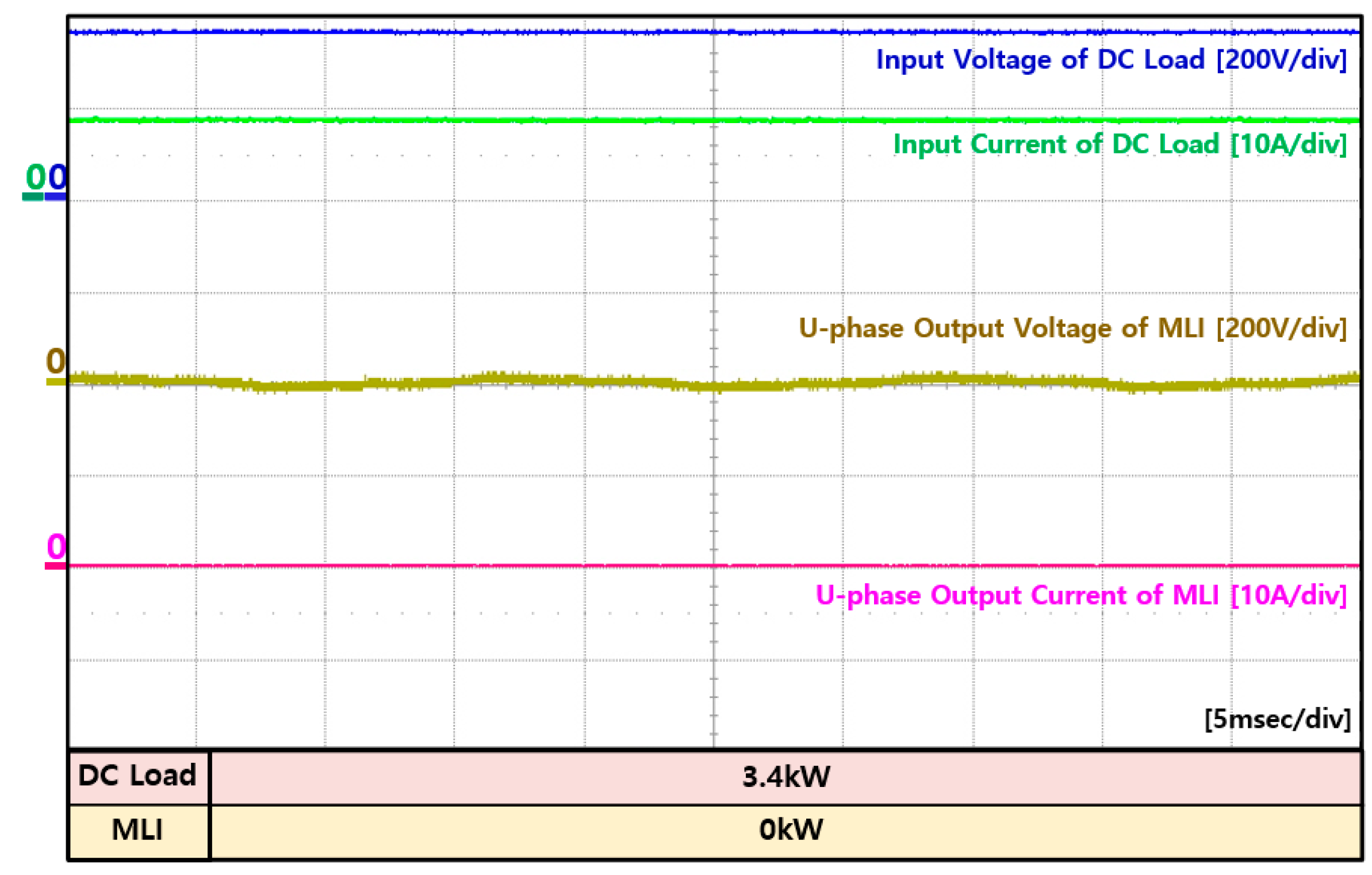
Energies 14 00581 g019
Figure 20. Experiment waveforms of DC load and multi-level inverter in mode 3.
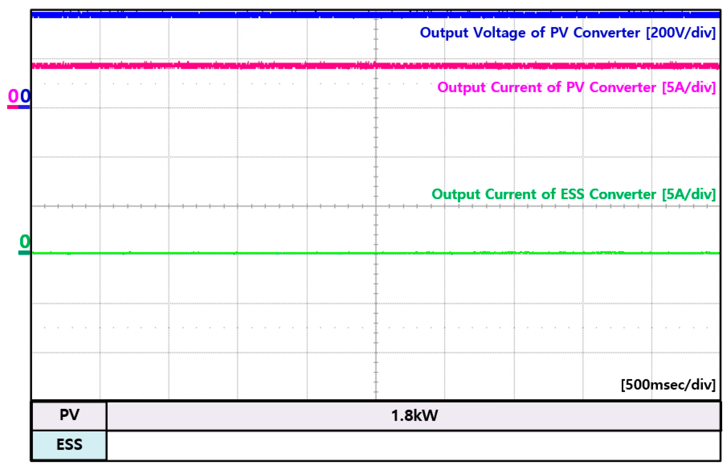
Energies 14 00581 g020
Figure 21. Experiment waveforms of PV converter and ESS converter in mode 3.
Energies 14 00581 g021
Figure 22. Experiment waveforms of interfacing converter and WT converter in mode 4.
Energies 14 00581 g022
Figure 23. Experiment waveforms of interfacing converter at AC grid in mode 4.
Energies 14 00581 g023
Figure 24. Experiment waveforms of DC load and multi-level inverter in mode 4.
Energies 14 00581 g024
Figure 25. Experiment waveforms of PV converter and ESS converter in mode 4.
Energies 14 00581 g025
Figure 26. Experiment waveforms of interfacing converter and WT converter in mode 5.
Energies 14 00581 g026
Figure 27. Experiment waveforms of interfacing converter at AC grid in mode 5.
Energies 14 00581 g027
Figure 28. Experiment waveforms of DC load and multi-level inverter in mode 5.
Energies 14 00581 g028
Figure 29. Experiment waveforms of PV converter and ESS converter in mode 5.
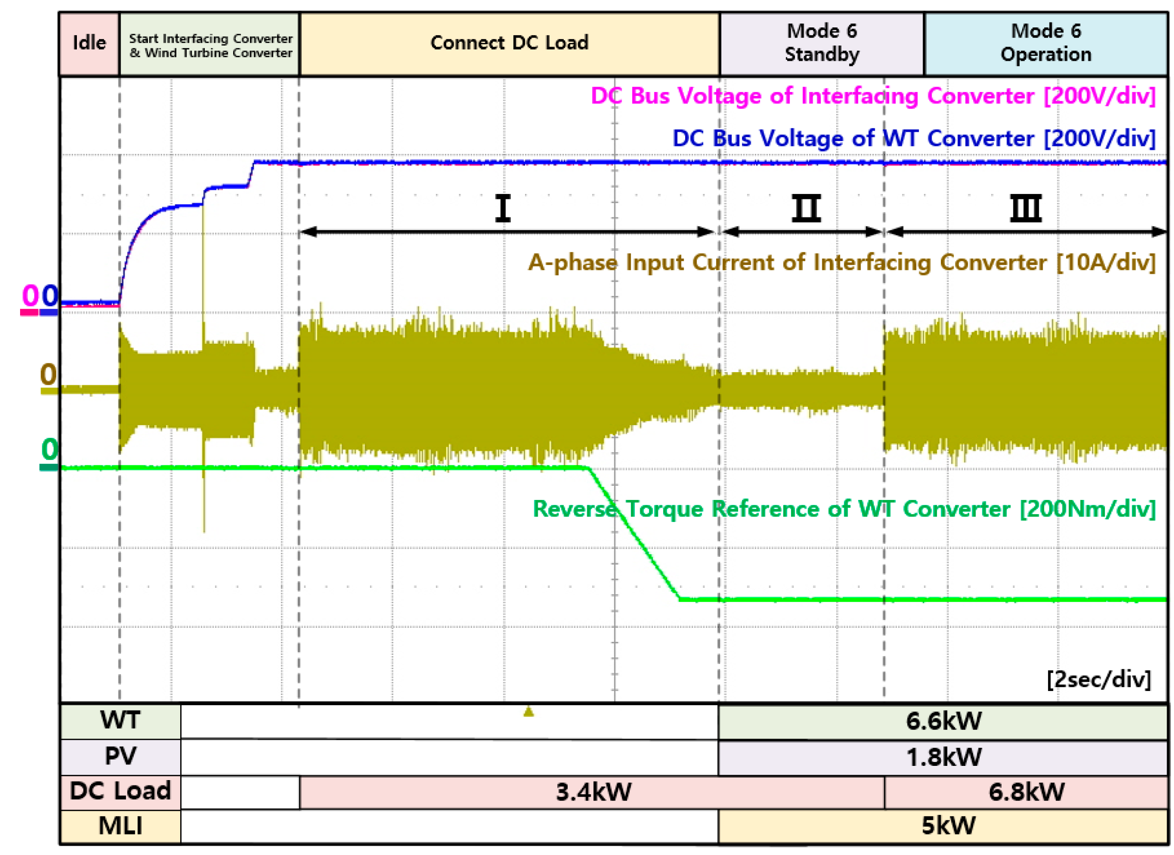
Energies 14 00581 g029
Figure 30. Experiment waveforms of interfacing converter and WT converter in mode 6.
Energies 14 00581 g030
Figure 31. Experiment waveforms of interfacing converter at AC grid in mode 6.
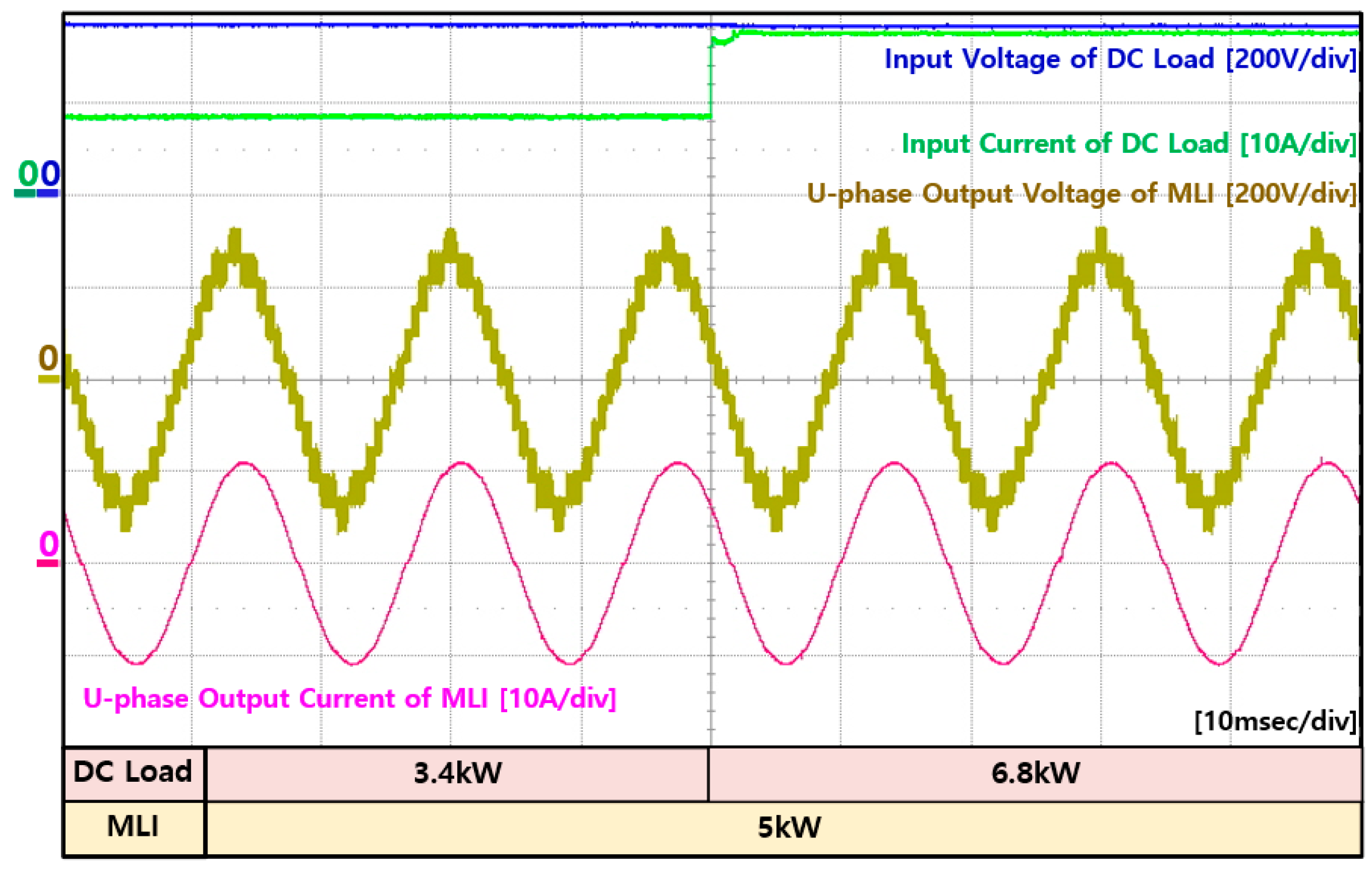
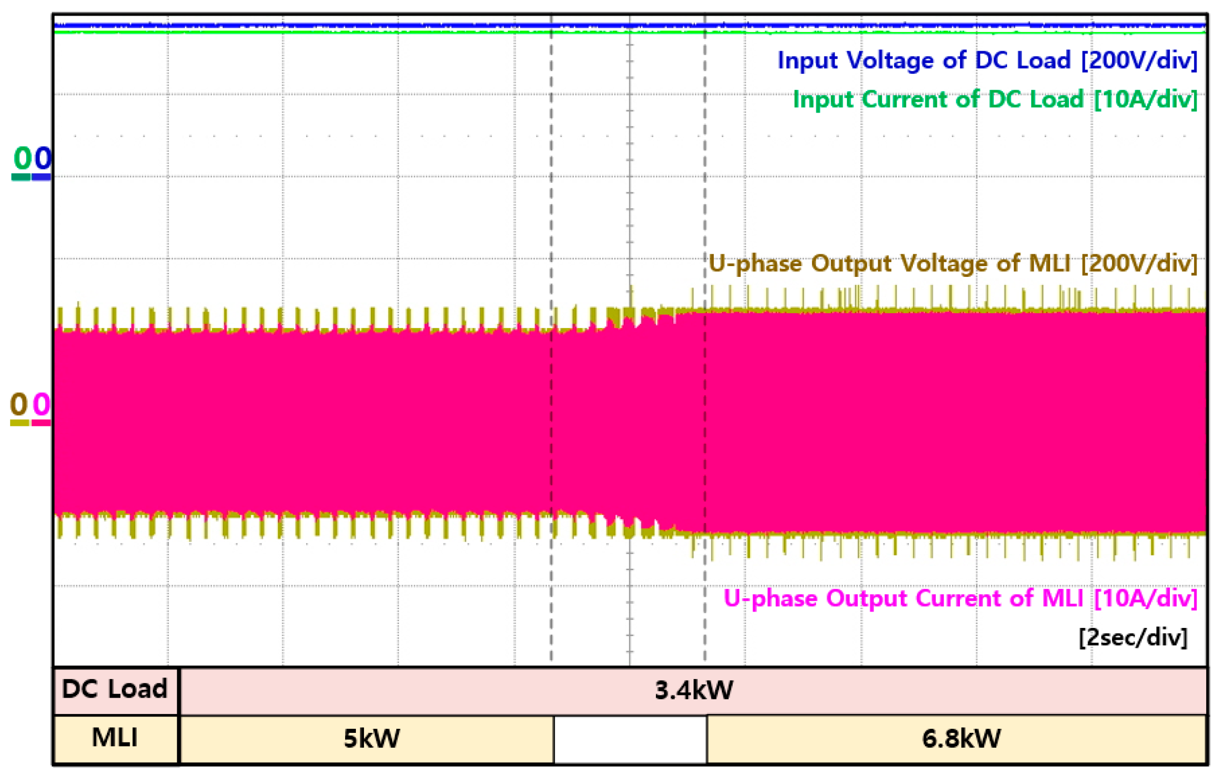
Energies 14 00581 g031
Figure 32. Experiment waveforms of DC load and multi-level inverter in mode 6.
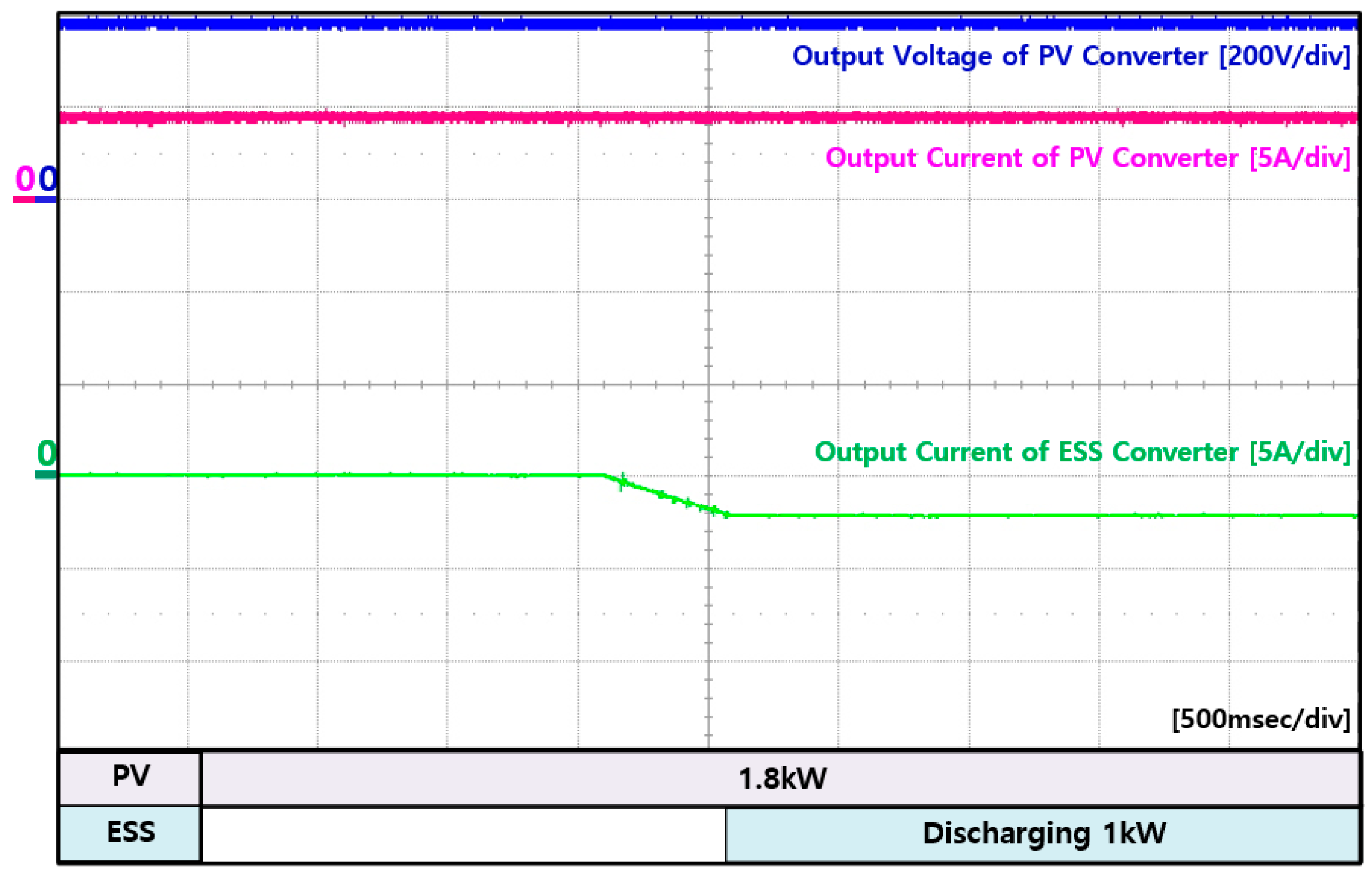
Energies 14 00581 g032
Figure 33. Experiment waveforms of PV converter and ESS converter in mode 6.
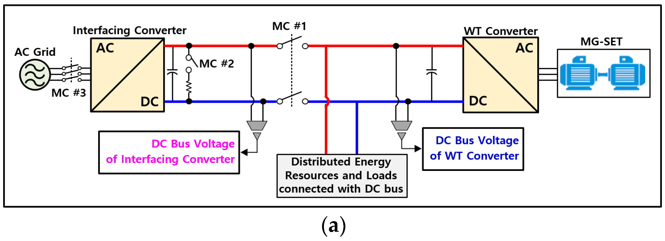
Energies 14 00581 g033
Figure 34. Experiment results of mode transition from grid-connected mode to stand-alone mode (a) configuration of experiment set-up, (b) waveforms of interfacing converter and WT converter.
Energies 14 00581 g034aEnergies 14 00581 g034b
Figure 35. Experiment waveforms of DC load and multi-level inverter in mode 7.
Energies 14 00581 g035
Figure 36. Experiment waveforms of PV converter and ESS converter in mode 7.
Energies 14 00581 g036
Figure 37. Experiment waveforms of DC load and multi-level inverter in mode 8.
Energies 14 00581 g037
Figure 38. Experiment waveforms of PV converter and ESS converter in mode 8.
Energies 14 00581 g038
Figure 39. Experiment waveforms of PV converter and ESS converter in mode 9.
Energies 14 00581 g039
Figure 40. Experiment waveforms of DC load and multi-level inverter in mode 9.
Energies 14 00581 g040
Table 1. Output power of each power conversion devices in mode 1.
ComponentsOutput Power [kW]ComponentsOutput Power [kW]
IIIIIIIIII
Interfacing Converter3.400ESS Converter001
PV Converter01.81.8Multi-Level Inverter055
WT Converter06.67.6DC Load3.43.43.4
Table 2. Output power of each power conversion devices in mode 2.
ComponentsOutput Power (kW)ComponentsOutput Power (kW)
IIIIIIIIIIII
Interfacing Converter3.40−1ESS Converter055
PV Converter01.81.8Multi-Level Inverter000
WT Converter06.67.6DC Load3.43.43.4
Table 3. Output power of each power conversion devices in mode 3.
ComponentsOutput Power (kW)ComponentsOutput Power (kW)
IIIIIIIIIIII
Interfacing Converter3.40−2ESS Converter000
PV Converter01.81.8Multi-Level Inverter055
WT Converter06.68.6DC Load3.43.43.4
Table 4. Output power of each power conversion devices in mode 4.
ComponentsOutput Power (kW)ComponentsOutput Power (kW)
IIIIIIIIIIII
Interfacing Converter3.400ESS Converter00−1
PV Converter01.81.8Multi-Level Inverter055
WT Converter06.65.6DC Load3.43.43.4
Table 5. Output power of each power conversion devices in mode 5.
ComponentsOutput Power (kW)ComponentsOutput Power (kW)
IIIIIIIVIIIIIIIV
Interfacing Converter002.32.3ESS Converter0−1−5−5
PV Converter1.81.81.81.8Multi-Level Inverter5557.3
WT Converter6.65.61.61.6DC Load3.43.43.43.4
Table 6. Output power of each power conversion devices in mode 6.
ComponentsOutput Power (kW)ComponentsOutput Power (kW)
IIIIIIIIIIII
Interfacing Converter3.403.4ESS Converter000
PV Converter01.81.8Multi-Level Inverter055
WT Converter06.66.6DC Load3.43.46.8
Table 7. Output power of each power conversion devices in mode 7.
ComponentsOutput Power (kW)ComponentsOutput Power (kW)
IIIIII
Interfacing Converter100ESS Converter01
PV Converter1.81.8Multi-Level Inverter54
WT Converter010DC Load6.86.8
Table 8. Output power of each power conversion devices in mode 8.
ComponentsOutput Power (kW)ComponentsOutput Power (kW)
IIIIII
Interfacing Converter100ESS Converter0−1
PV Converter1.81.8Multi-Level Inverter56
WT Converter010DC Load6.86.8
Table 9. Output power of each power conversion devices in mode 9.
ComponentsOutput Power (kW)ComponentsOutput Power (kW)
IIIIII
Interfacing Converter100ESS Converter−1.6−5
PV Converter1.81.8Multi-Level Inverter00
WT Converter010DC Load3.46.8
Publisher’s Note: MDPI stays neutral with regard to jurisdictional claims in published maps and institutional affiliations.

