Abstract
The paper presents the novel use of analytical models of a beam on an elastic foundation. The one-parameter model (Winkler model) and the two-parameter models (Filonenko-Borodich and Pasternak models) were investigated. These models were used to describe the elastic response of axially loaded blind rivets used with sandwich structures. The elastic response related to the elastic strain energy is mentioned in the paper as the resilience modulus of the connection. The databases from laboratory pull-out tests were used to verify these models. One type of blind rivet (aluminum, with three clamping arms) and one type of sandwich beam were used. The sandwich beams used in the experiments consisted of two thin-walled and stiff external facings (zinc-coated steel) and a thick, soft core (polyisocyanurate foam—PIR). In the test the sandwich beams were subjected to static, axial pull-out loading. The research provides the quantitative comparison between the laboratory experiment and the analytical solutions from models adopted for this type of connection. Additionally, the failure mechanisms, the secant stiffness at the ultimate capacity, and the strain energy capacity of the elastic foundation at failure are considered. To the author’s knowledge, this approach has not been described in the literature so far.
1. Introduction
The research refers to sandwich panels which are composite structures consisting of two thin-walled external facings and a thick core [1]. The facings of the considered sandwich panel are made of high strength material, i.e., zinc-coated steel, while the core is made of thermal insulation material of a low density, such as polyisocyanurate foam (PIR foam). From a mechanical point of view, the core ensures the distance between the facing, which leads to a significant increase of the stiffness of the panel with a negligible increase in its mass [2,3].
This type of sandwich panel is used in building engineering applications as roof- and wall-cladding elements. The modern approach to the use of cladding surfaces of buildings makes it necessary to allow for the installation of advertising signs, solar panels, and building installations. In that case the typical mounting systems use the through-drilling fasteners which, due to the large thermal conductivity of the steel (λ = 50 W/mK), are the source of thermal bridges. The thermal bridges result in an overall reduction in the thermal resistance of the building and may cause condensation within the building envelope [4,5], while the additional supporting structure means an increase of the weight of the structure. Furthermore, this mounting system requires an additional supporting structure. Considering the above, it is justified to attach external (additional) elements to the building envelope via the blind rivets. The blind connection is realized only with one facing (external or internal) thus the core layer and the opposite facing layer remain untouched. Therefore, the use of the blind rivets eliminates the drawbacks of through-drilling fastener mounting systems.
In the subject literature, there are very limited references to this type of connection with sandwich panels used in building engineering applications. The very first references concerning the use of blind rivets with sandwich panels can be found in patents documents from the 1960s [6] and 1980s [7,8]. The load capacity of a one-sided connection subjected to static and fatigue axial tension is presented in [9,10] and [11] respectively. Recently the influence of suspended loads using blind rivets on the load capacity of the sandwich panels was presented in [12], which discusses the results of experimental tests including several levels of suspended loads and their effect on sandwich beams with a core made of polyurethane foam, mineral wool and styrofoam. The experimental and numerical investigation of the use of blind rivets with sandwich panels with PIR foam core is discussed in [13], underlining the aspect of both the facing material (laminate or steel) and the type of blind rivet (rivet with three or four folds). Paper [14] continues the research presented in [13], by considering the load type (axial and eccentric), the load nature (static and quasi-cyclic), and the material of the core layer (PIR foam, mineral wool and expanded polystyrene). This paper extends the results of [13,14], providing the analytical models describing the behavior of a blind connection used with sandwich panels. The validation of the analytical models is based on new laboratory tests, performed on the same testbed as the tests in [13,14].
In the subject literature of sandwich and composite structures, strain energy is widely used. In [15] it was revealed that the strain energy updating technique used in the high-order zig-zag models provides information about the facing damage with reasonable accuracy. The strain energy release rate measurement can be also used for the determination of the fracture of fiber-reinforced polymer laminates. This approach was used to predict the delamination of laminated composites [16] and to describe the use of the six-lobed shaped glass fibers [17]. It is worth mentioning that the finite element modeling of multilayered shell structures can be improved by the strain energy updating techniques (SEUPT), see [18]. Recently, in [19], the problem of the localization and quantification of the debonding failure in sandwich panels was solved by the means of the modal strain energy method.
To the best of the author’s knowledge, the use of the analytical models of a beam on an elastic foundation to describe the elastic response of axially loaded blind rivets used with sandwich structures has not been considered in the literature so far. This research provides the connection between the beginning of the failure of the connection with the resilience modulus. The resilience modulus represents the amount of elastic strain energy stored by the connection.
2. Materials and Methods
In the subject literature, there is a number of analytical models (also called elastic models) that describe the beam on an elastic foundation. These models assume that the stress depends only on the strain neglecting the load history and the beam (an infinitely long Bernoulli-Euler beam) [20]. Therefore, it means that these analytical models do not involve whole possible engineering cases and their usefulness is limited. The analytical models can be also characterized as simple mathematically but problematic when determining the model parameters. Below, the one-parameter model (Winkler model) and the two-parameter models (Filonenko-Borodich and Pasternak models) are shortly described.
2.1. Winkler Model (1867)
In Winkler’s idealization [21], the foundation layer is represented as a system of identical but mutually independent, closely spaced, discrete, linear elastic springs. According to this idealization, the deformation of the foundation layer due to the applied load is confined to the loaded regions only. Thus, this model essentially suffers from a complete lack of continuity in the supporting medium. Figure 1 depicts the physical representation of the Winkler model.
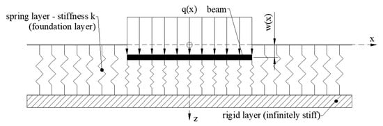
Figure 1.
Beam on elastic foundation—Winkler model.
The differential equation of a beam in Winkler model is given by Equation (1).
where
- w(x) represents a deflection of the beam (mm);
- ;
- E represents a Young’s modulus of the beam (N/mm2);
- I represents a second moment of inertia of the cross section of the beam (mm4);
- q(x) represents a vertical load on the beam (N/mm);
- k represents a coefficient of spring layer reaction or spring layer modulus (N/mm3);
- B represents an effective width of the beam and the foundation layer (mm).
The fundamental problem with the use of the Winkler model is to determine the coefficient of springs k used to replace the elastic foundation layer, which depends not only on the nature of the supporting medium but also on the dimensions of the loaded area. In 1955 Terzaghi [22] introduced the approximate definition of coefficient k of the supporting medium, see Equation (2) and Figure 2.
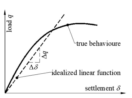
Figure 2.
Load–deformation response of the supporting medium.
2.2. Filonenko-Borodich Model (1940)
The Filonenko-Borodich model is a two-parameter model [23,24]. This model assures continuity between the individual springs in the Winkler model by connecting them to thin elastic membranes which are under the constant tension T. The differential equation of a beam in the Filonenko-Borodich model is expressed by Equation (3),
where
- w(x), , E, I, B, q(x), and k are the parameters described under the Equation (2);
- ;
- T represents a tensile force in a thin elastic membrane (N).
In Figure 3, the physical representation of the Filonenko-Borodich model is depicted.
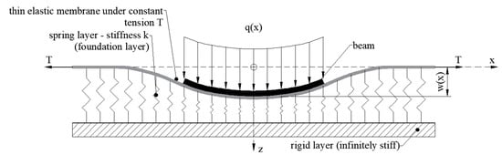
Figure 3.
Beam on elastic foundation—Filonenko-Borodich model.
2.3. Pasternak Model (1954)
In this model, the existence of shear interaction among the springs is assumed by connecting the ends of the springs to a beam that only undergoes transverse shear deformation [24,25]. The load–deflection relationship is obtained by considering the vertical equilibrium of the shear layer. The differential equation of a beam in the Pasternak model is expressed by Equation (4),
where
- w(x), , E, I, B, q(x), and k are the parameters described under Equation (2);
- ;
- G represents a shear modulus of the introduced shear layer (N/mm2).
In Figure 4, the physical representation of the Pasternak model is presented.
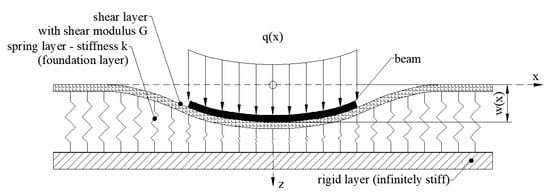
Figure 4.
Beam on elastic foundation—Pasternak model.
It can be noticed that the second parameter in the two-parameter models is introduced to provide the continuity of the springs, thus the two-parameter models remedy the shortcoming involving the discontinuity of the spring deformation of the Winkler model. In the paper the accuracy of the use of the one-parameter model (Winkler—1867) and two-parameter models (Filonenko-Borodich—1940, Pasternak—1954) will be investigated for the case of a pull-out of a blind rivet from a sandwich beam facing, see Figure 5. It is assumed that the external upper thin-walled facing is the beam and the core is the elastic foundation. The origin is set at the loading point in the center of the external facing, the abscissa is the distance x and the ordinate is the deflection z. The considered cases are symmetrical about the z–z axis.
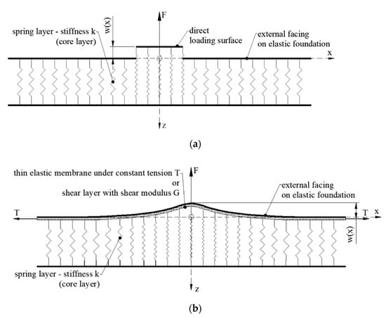
Figure 5.
Facing–core interaction according to analytical models: (a) Winkler model, (b) Filonenko-Borodich/Pasternak model.
2.4. Experimental Approach
To assess the accuracy of the analytical models for the pull-out of a blind rivet from the sandwich beam facings the laboratory experiments were carried out. The statistical sample size was 5. In the tests rectangular sandwich beams of 350 mm in length (L) and 60 mm in width (B) were used. The sandwich beams consisted of a PIR foam core layer (ρC = 40 kg/m3) of the nominal thickness dC = 60 mm and two external facings made of grade S 280GD steel of the nominal thickness tF = 0.51 mm. In the experiment both ends of the sandwich beam were fixed. The mechanical properties of the sandwich beam layers were obtained from subject literature (*) and from the standardized tests according to EN ISO 6892-1 [26] and EN 14509 [27]:
- EF = 186.0 × 10³ ± 2.5 × 10³ N/mm2 represents Young’s modulus of facings;
- νF* = 0.30 represents Poisson’s ratio of facings;
- EC = 5.7 ± 0.12 N/mm2 represents Young’s modulus of core;
- ΝC* = 0.05 Poisson’s ratio of core’
- GC = EC/2 × (1 + νC) = 2.71 N/mm2 represents Kirchhoff’s modulus.
In the experiment a threefold aluminum rivet, which consists of a hat 4.76 mm (3/16′’) in diameter, a neoprene washer and mandrel was used, see Figure 6. The blind rivet was installed in the middle of the upper facing of the sandwich beam.
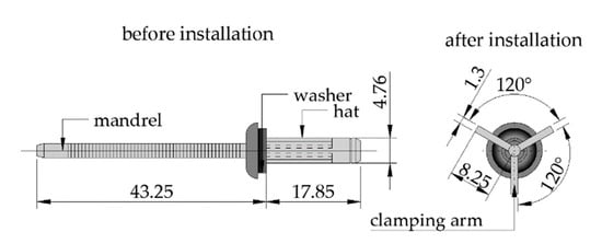
Figure 6.
Geometrical parameters of the aluminum blind rivet with three clamping arms.
The uplift static load was applied to the blind rivet by the loading cell without eccentrics with a speed of 2 mm/min. During the test, the load and the displacement of both the unit cell and the bottom facing of the sandwich beam were measured. Figure 7 includes the scheme of the test bed and a photo from the laboratory test.
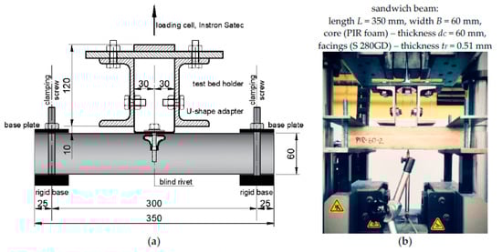
Figure 7.
Test bed of the pull-out blind rivets: (a) technical scheme (dimensions in mm), and (b) real view.
3. Results
In Figure 8, the load–displacement curves of the pull-out of the blind rivet from the external facing are depicted. The continuous grey lines represent the particular pull-out tests while the thick black line represents the average of all pull-out test trials. The intersection point (black dot at the graphs at an ordinate of ~100 N) represents the divergence point of the load–displacement lines. Additionally, at this load level (Fi = ~100 N) during the tests, sounds of cracking PIR foam could be heard. It means that the facing and the core layer started separating. The area under the curve (up to the Fi load level) can be considered as elastic strain energy, i.e., if we unload the test sample, the facing will return to the original shape by releasing stored strain energy. This ability is referred to as resilience. The resilience is expressed as the modulus of resilience, which is the amount of strain energy the material can store per unit of volume without causing permanent deformation. The resilience can be obtained by calculating the area under the stress–strain curve, up to the elastic limit.
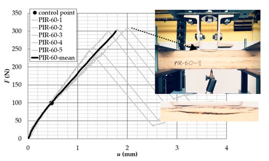
Figure 8.
Load–displacement curves of the pull-out of a blind rivet from the sandwich beam facing.
At the horizontal axis, the resultant displacement—meant as the difference between the displacement of the loading cell and the deflection of the bottom of the sandwich beam—is measured. The ultimate capacity varies from about 240 N (sample PIR-60-2 and PIR-60-5) to about 300 N (sample PIR-60-1, PIR-60-3, and PIR-60-4). The failure mechanisms observed during the tests were the same for all samples. The failure was manifested by the delamination of the loaded facing in the vicinity of the blind rivet and by the fracture failure of the core layer and the free edges, see Figure 8.
In Table 1, detailed results from the laboratory tests are presented:

Table 1.
Results from laboratory tests.
- Fi (N) and Fult (N) represent the force at the intersection point and for the ultimate capacity, respectively;
- ui (mm) and uult (mm) represent the displacement at the intersection point and for the ultimate capacity, respectively;
- ki (N/mm) and kult (N/mm) represent the stiffness at the intersection point and at the ultimate point (secant stiffness), respectively;
- ASE (J) is the area under the load–displacement lines, which can be interpreted as the strain energy capacity of the elastic foundation at failure.
4. Discussion
The correctness of the analytical models (one- and two-parameter models) will be verified for the maximum load level common for all tests (Fi = 100.3 N and ul = 0.473 mm, see Table 1 and Figure 7). The static scheme of the considered beam (the facing of the sandwich beam with the attached blind rivet) on an elastic foundation (the core layer of the sandwich beam) is depicted in Figure 9. From the experiments, the following parameters for one- and two-parameter models have to be obtained, see Section 4.1, Section 4.2 and Section 4.3, respectively.
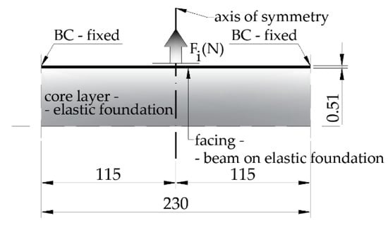
Figure 9.
Geometrical parameters (in mm) of the aluminum blind rivet with three clamping arms.
4.1. Coefficient of Spring Layer Reaction
The one- and two-parameter models require the coefficient of spring layer reaction k, see Equations (1), (3) and (4). The parameter k can be obtained according to the Equation (2) [12], thus the concentrated force has to be transformed into uniformly distributed load q = Fi/AF, where AF is direct loading surface which refers to the size of the failure zone, see Equation (5).
Having the k parameter, we can solve the differential equation of the Winkler model—Equation (1), by simple rearrangements and by introducing the auxiliary parameter α given by Equation (6).
where EF = 186.0 × 10³ (N/mm2) represents the Young’s modulus of the external facing and (mm4) represents the second moment of inertia of the external facing. In the subject literature, the parameter α is also called a characteristic value of the Bernoulli-Euler beam on the Winkler model. Equation (1) takes the following form:
The solution of Equation (7) consists of the special integral of the non-homogeneous equation, ws(x) and the general integral of the homogeneous equation, wg(x), see Equation (8).
The special solution of the non-homogeneous equation depends on the load. For the case of concentrated load , thus Equation (8) takes the following form . Please note that this is valid also for the Filonenko-Borodich and the Pasternak models. The general solution of the homogeneous differential equation of the form gives the following characteristic equation, Equation (9).
The general solution of the homogeneous Equation (9) is expressed by Equation (10).
The determination of integration constants (A1–A4) requires the introduction of appropriate boundary conditions. Due to the symmetry of the task (Figure 9), the boundary conditions will be determined for x = 0.0 mm (center of the beam) and x = 115.0 mm (right end of the beam), see Table 2.
Table 2.
The boundary conditions of the facing of the sandwich beam on the elastic foundation (core layer) subjected to the pull-out of the blind rivet test—analytical model.
Taking into account the boundary conditions given in Table 2, the following integration constants of Equation (10) have been determined: A1 = 1.34 × 10⁻⁶, A2 = −1.75 × 10⁻⁶, A3 = 0.5325, A4 = 0.5325.
4.2. Tensile Force T—Second Parameter in Filolenko-Borodich Model
Two-parameter models require a second parameter. In the case of the Filonenko-Borodich model, this is the tensile force T. This force can be obtained from the numerical experiment. The shell numerical model of a facing on the elastic foundation (surface support stiffness Kz = k = 0.09 N/mm3) was created in the AxisVM program. Figure 10 presents the distribution of both the tensile force (Nx = T) along the facing and its deformation. The tensile force T = 99.0 N will be assigned in the Filonenko-Borodich model. Note that there is a good agreement between the measured displacement of the pull-out blind rivet in the laboratory experiment with the numerical one, the difference is 3.2%, i.e., δFEM = 0.488 mm vs. δLAB = 0.473 mm.
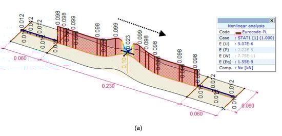
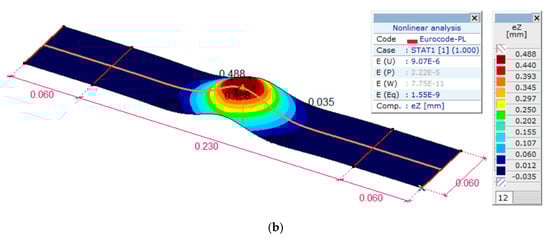
Figure 10.
Numerical results of a shell FE model in the AxisVM program. Distribution of: (a) the tensile force Nx, (b) the deformation ez.
Having both parameters of Filonenko-Borodich model (k and T) the general integral of the ordered differential equation takes the following form.
where
- (mm−1) is the characteristic value of the Bernoulli-Euler beam on the Winkler model, see Equation (6);
- (mm−1) is the characteristic value of the Filolenko-Borodich model;
- .
The general solution of the homogeneous differential equation of a form gives the following characteristic equation of the Filonenko-Borodich model, Equation (12). Note that due to the type of loading (concentrated force) the special solution of the non-homogeneous equation is :
The roots of the Equation (12) are
Therefore, there are three possible solutions of Equation (11):
- : r consists of two pairs of the conjugated complex numbers; and ;
- : r consists of one pair of real numbers ;
- : r consists of two pairs of real numbers; and ;where and .
In our case , which leads to the following general solution of Equation (14).
where (mm−1) and (mm−1).
Considering the same boundary conditions as for the Winkler model we obtained the following integration constants: B1 = 0.5171, B2 = −8.2 × 10⁻⁷, B3 = 0.5495, and B4 = 8.3 × 10⁻⁷.
4.3. Modulus of Shear Layer GC—Second Parameter in Pasternak Model
The third analytical model, i.e., the Pasternak model, is mathematically the same as the Filonenko-Borodich by simply replacing the BT by BGC. It was assumed that the shear modulus of the core layer will define the shear modulus of the introduced shear layer in the Pasternak model. Having both parameters of the Pasternak model (k and GC) the general integral of the ordered differential Equation takes the following form:
where:
- (mm−1) is the characteristic value of the Bernoulli-Euler beam on the Winkler model, see Equation (6);
- (mm−1) is the characteristic value of the Pasternak model;
- .
In our case .9004, which leads to the following general solution of Equation (15).
where (mm−1) and (mm−1).
Considering the same boundary conditions as for the Winkler model we obtained the following integration constants: C1 = 0.5079, C2 = −4.7 × 10⁻⁷, C3 = 0.5612, and C4 = 5.2 × 10⁻⁷.
The deflection lines of a facing on the elastic foundation of Winkler model, Pasternak model and Filonenko-Borodich model are depicted in Figure 11. The continuous line represents the Winkler model, the dotted line represents the Filolenko-Borodich model and the dashed line represents the Pasternak model. The results from the laboratory experiment were also added.
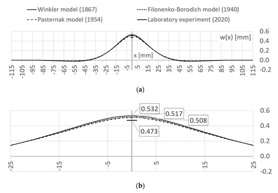
Figure 11.
Displacement lines of the pull-out of the blind rivet obtained from analytical models and from the experiment: (a) whole displacement line, (b) zoomed range.
5. Conclusions
The paper presents the use of the analytical models to describe the elastic range of the mechanical response of the pull-out of the blind rivet from a sandwich beam facing. The one- and the two-parameter models were investigated and verified with the laboratory tests. The following detailed conclusions can be distinguished:
- From the practical point of view, the use of the blind rivets with sandwich panels should be limited to the elastic response of the connection, which is related to the resilience modulus (i.e., the amount of strain energy the connection can store without causing permanent deformation);
- All presented analytical models allow for the description of the elastic range of mechanical response of the pull-out test of the blind rivet from the sandwich panels;
- The considered analytical models slightly overestimate the displacement of the facing subjected to pull-out loading with respect to laboratory results, i.e., the size of the overestimation of the displacements for Winkler model equals 12.6% (δW = 0.532 mm vs. δLAB = 0.473 mm), for the Filonenko-Borodich model equals 9.3% (δF = 0.517 mm vs. δAB = 0.473 mm) and for Pasternak model equals 7.4% (δP = 0.508 mm vs. δLAB = 0.473 mm);
- The presented study can be easily extended to the 2D model to describe the mechanical response of the pull-out test of the blind rivet from the sandwich panel facing.
Funding
The research was financially supported by Poznan University of Technology Grant no. 0412/SBAD/0044.
Institutional Review Board Statement
Not applicable.
Informed Consent Statement
Not applicable.
Data Availability Statement
Not applicable.
Conflicts of Interest
The author declares no conflict of interest.
References
- Zenkert, D. Introduction to Sandwich Construction; Engineering Materials Advisory Services Ltd.: Worcestershire, UK, 1995; ISBN 0947817778. [Google Scholar]
- Plantema, F.J. Sandwich Construction; John Wiley & Sons: New York, NY, USA, 1996. [Google Scholar]
- Allen, H.G. Analysis and Design of Structural Sandwich Panels; Pergamon Press: Oxford, UK, 1969. [Google Scholar]
- Quinten, J.; Feldheim, V. Dynamic modelling of multidimensional thermal bridges in building envelopes: Review of existing methods, application and new mixed method. Energy Build. 2016, 110, 284–293. [Google Scholar] [CrossRef]
- Capozzoli, A.; Gorrino, A.; Corrado, V. A building thermal bridges sensitivity analysis. Appl. Energy 2013, 107, 229–243. [Google Scholar] [CrossRef]
- Lawrence, F.W. Blind Fastener for Sandwich Panel and Method. U.S. Patent no. 3434262 A, 25 March 1969. [Google Scholar]
- Worthing, A.L. Sandwich Panel Fastener. U.S. Patent no. 4846612 A, 11 July 1989. [Google Scholar]
- Gauron, R.F. Inset Panel Fastener and Method of Using. U.S. Patent no. 4812193 A, 14 March 1989. [Google Scholar]
- Gosowski, B.; Gajewski, M.; Gosowski, M. Test of blind rivet connections in structural steel elements. Inżynieria i Budownictwo 2004, 11, 615–619. (In Polish) [Google Scholar]
- Gosowski, B. Design engineering and working issues related to sandwich panel cladding. Part 2: Testing load-bearing capacity of sandwich panel to supporting structure joints. Izolacje 2016, 4, 60–67. (In Polish) [Google Scholar]
- Biccari, D.; Genovese, K.; Pappalettere, C. Static and Fatigue Behaviour of Sandwich Composite Panels Joined by Blind Fasteners. Key Eng. Mater. 2001, 221–222, 61–70. [Google Scholar] [CrossRef]
- Studziński, R.; Ciesielczyk, K. Influence of suspended loads using blind rivets on the load capacity of the sandwich panels. Buildings 2020, 3. (In Polish) [Google Scholar] [CrossRef]
- Studziński, R. Experimental investigation of the use of blind rivets in sandwich panels. J. Sandw. Struct. Mater. 2020. [Google Scholar] [CrossRef]
- Studziński, R.; Ciesielczyk, K. Use of Blind Rivets in Sandwich Panels—Experimental Investigation of Static and Quasi-Cyclic Loading. Buildings 2020, 10, 155. [Google Scholar] [CrossRef]
- Icardi, U.; Ferrero, L. Impact analysis of sandwich composites based on a refined plate element with strain energy updating. Compos. Struct. 2009, 89, 35–51. [Google Scholar] [CrossRef]
- Shokrieh, M.M.; Zeinedini, A. A Novel Method for Calculation of Strain Energy Release Rate of Asymmetric Double Cantilever Laminated Composite Beams. Appl. Compos. Mater. 2014, 21, 399–415. [Google Scholar] [CrossRef]
- Harris, J.; Bond, I.P.; Weaver, P.M.; Wisnom, M.R.; Rezai, A. Measuring strain energy release rate (GIc) in novel fibre shape composites. Compos. Sci. Technol. 2006, 66, 1239–1247. [Google Scholar] [CrossRef]
- Icardi, U. Extension of the Strain Energy Updating Technique to a Multilayered Shell Model with Adaptive Displacements and Fixed DOF. J. Aerosp. Eng. 2013, 842–854. [Google Scholar] [CrossRef]
- Meruane, V.; Lasen, M.; Lopez Droguett, E.; Ortiz-Bernardin, A. Modal Strain Energy-Based Debonding Assessment of Sandwich Panels Using a Linear Approximation with Maximum Entropy. Entropy 2017, 19, 619. [Google Scholar] [CrossRef]
- Vallabhan, C.V.G.; Das, Y.C. Parametric study of beams on elastic foundation. J. Eng. Mech. 1988, 114, 2072–2082. [Google Scholar] [CrossRef]
- Winkler, E. Die Lehre von der Elasticitaet und Festigkeit; Dominicus, H., Ed.; Bayer Staatsbibliothek: Munich, German; Prague, Czech Republic, 1867. (In German) [Google Scholar]
- Terzaghi, K. Evaluation of Coefficients of Subgrade Reaction. Géotechnique 1955, 5, 297–326. [Google Scholar] [CrossRef]
- Filolenko-Borodich, M.M. Some approximate theories of elastic foundation. Uchenyie Zapiski Moskovskogo Gosudarstuennogo Universiteta Mekhanika 1940, 46, 3–18. (In Russian) [Google Scholar]
- Tanahashi, H. Formulas for an infinitely long Bernoulli-Euler beam on the Pasternak model. Soils Found. 2004, 44, 109–118. [Google Scholar] [CrossRef]
- Pasternak, P.L. On a new method of an elastic foundation by means of two foundation constants. Gos. Izdatelstvo Literaturi po Stroitelstuve i Arkhitekture 1954. Available online: https://ci.nii.ac.jp/naid/10013393533/ (accessed on 22 January 2021). (In Russian).
- EN ISO 6892-1. Metallic Materials-Tensile Testing-Part 1: Method of Test at Room Temperature; NSAI: Dublin, Ireland, 2016. [Google Scholar]
- EN 14509. Self-Supporting Double Skin Metal Faced Insulating Panels-Factory Made Products–Specifications; CEN-CENELEC Management Centre: Brussels, Belgium, 2007. [Google Scholar]
Publisher’s Note: MDPI stays neutral with regard to jurisdictional claims in published maps and institutional affiliations. |
© 2021 by the author. Licensee MDPI, Basel, Switzerland. This article is an open access article distributed under the terms and conditions of the Creative Commons Attribution (CC BY) license (http://creativecommons.org/licenses/by/4.0/).