Implementation of Resilient Self-Healing Microgrids with IEC 61850-Based Communications


Abstract
1. Introduction
2. IEC 61850 Modeling and System Structure
3. F-FDIR
- The target networked microgrid system is operating in a grid-connected mode.
- The target system has a communication backbone system, e.g., wireless or wired.
- Each switch has a communication capability to send measurements (e.g., currents and voltages) and receive control commands.
- Each switch may have a capability to interrupt the load currents.
- Each switch may have a directional fault indicator (DFI) capability, or they can receive the DFI information from the external DFI devices.
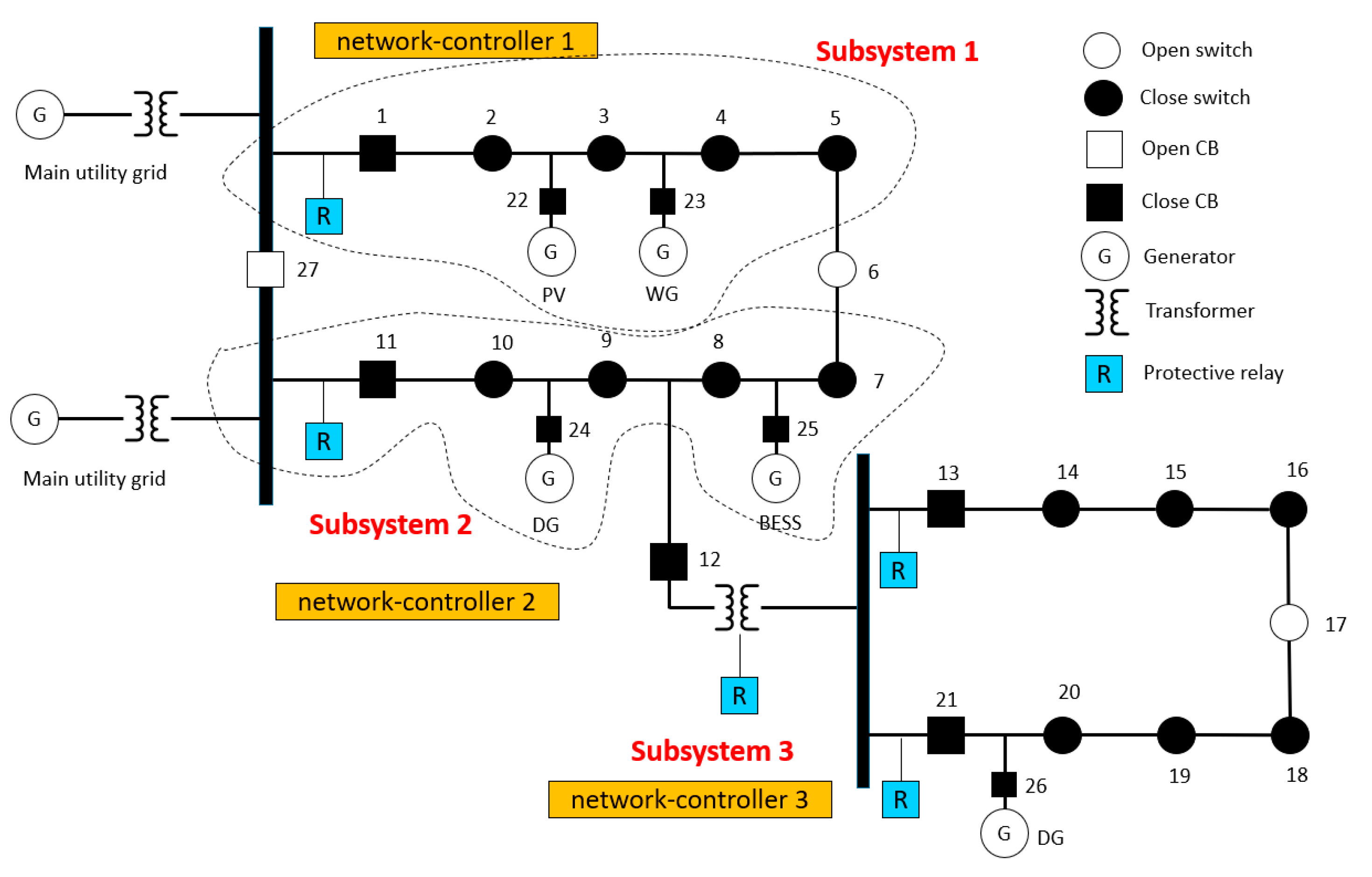
- Each subsystem has its own network-controller (i.e., microgrid controller) for monitoring, control and settings change as shown in Figure 2.
- The network-controllers of each subsystem can communicate with each other.
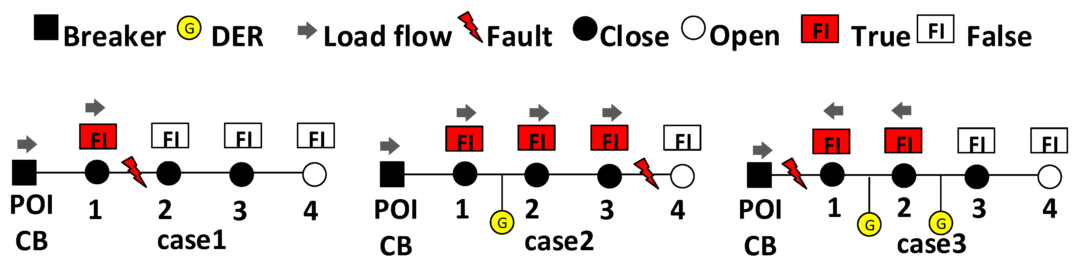
| Algorithm 1. Topology Based Fault Location Detection |
| 1 Input: Measurements and statuses of field devices, information from protective IEDs, and DFIs from switches Output: Location of the faulted section within the microgrid feeder |
| 2 STATUS(, , , , , , , ) |
| 3 if () then |
| 4 Calculate topology-based fault location detection, FD(STATUS()) |
| 5 for 1:Number of switches do |
| 6 get(before the event, STATUS()) |
| 7 get(after the event, STATUS()) |
| 8 End |
| 9 Check DFIs (, ); |
| 10 if (DFIs are pointing same direction) then |
| 11 Fault at the next section of the last DFI |
| 12 elseif (DFIs are pointing same point of section) then |
| 13 Fault at the pointing section |
| 14 end |
| 15 end |
| Algorithm 2. Faulted Section Isolation |
| 1 Input: Measurements and statuses of field devices, and status feedback from the switches and DERs Output: Isolation of faulted section within microgrids |
| 2 STATUS(, , , ) |
| 3 Check the status of the target CB and switches: , |
| 4 if (( = close) ( = close)) then |
| 5 Send open command to SW i and CB i |
| 6 if (( = open) ( = open)) then |
| 7 else, check if (() ()) then |
| 8 re-send open command to SW i and CB i |
| 9 Check the heartbeat of SW i and CB i: , |
| 10 if (( = false) ( = false)) then |
| 11 Extend the isolation section, and then send open command to SW i1 and CB i1 |
| 12 Go back to step 6, repeat N times |
| 13 End |
| 14 End |
| 15 End |
| 16 if DER exists within the faulted section then |
| 17 Send open command to SW i |
| 18 if = close then reduce power order of DER i to min. set = minimum |
| 19 End |
| 20 End |
| Algorithm 3. System restoration |
| 1 Input: Measurements and statuses of field devices, and status feedback from the switches and DERs Output: Restoration of healthy section within microgrids |
| 2 STATUS(, , , , ) |
| 3 Restore healthy upstream section (exception applied: 1-1, 2-1, … 8-1) |
| 4 if island exists then |
| 5 if island has DER then |
| 6 if island > island then |
| 7 if > island then transfer loads |
| 8 else then check critical load within island |
| 9 ifcritical, island > after load shedding then pick up critical loads |
| 10 end |
| 11 end |
| 12 else then (1) shedding DERs within island or |
| 13 (2) transfer DERs to another subsystem |
| 14 end |
| 15 else restore remaining healthy loads (steps 7~11) |
| 16 end |
| 17 End |
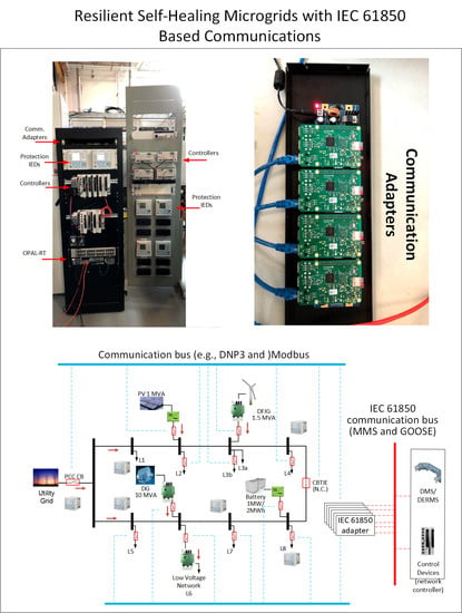
4. HIL Testbed
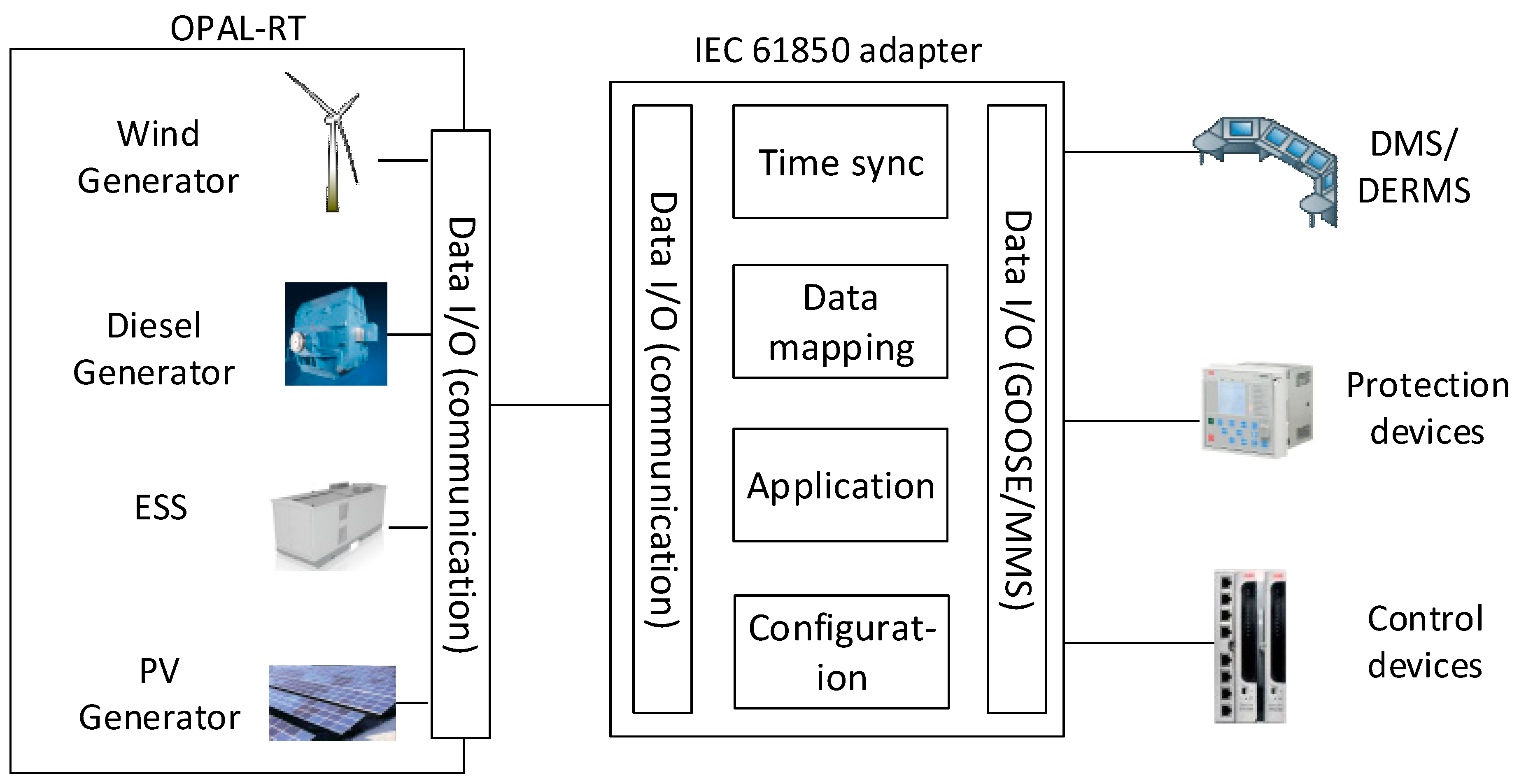
4.1. IEC 61850 Communication Adapter
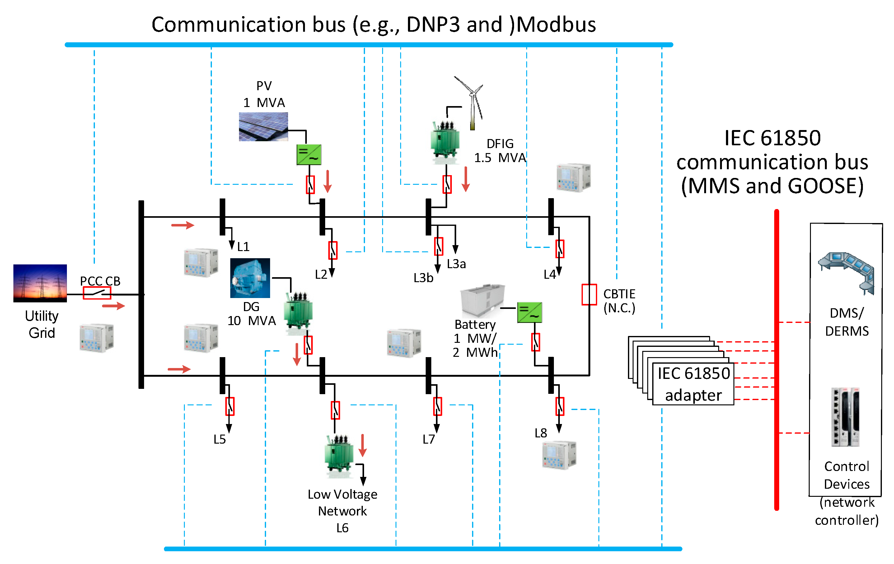
4.2. IEC 61850 Based HIL Testbed
5. Case Study
5.1. Case Study 1: Validation of IEC 61850 Adapter
5.2. Case Study 2: F-FDIR
6. Conclusions
Author Contributions
Funding
Institutional Review Board Statement
Informed Consent Statement
Data Availability Statement
Conflicts of Interest
Nomenclature
| Measured current of switch i at time t | |
| Measured voltage of switch i at time t | |
| Status of switch i (st = open or close) at time t | |
| Directional fault indicator of switch i at time t | |
| Heartbeat (i.e., comm.) of switch i at time t | |
| Measured current of CB i at time t | |
| Measured voltage of CB i at time t | |
| Status of CB i (st = open or close) at time t | |
| Directional fault indicator of CB i (DFI = true (forward or backward) or false) at time t | |
| Heartbeat (i.e., comm.) of CB i at time t | |
| Active and reactive power information of load i | |
| Generation capability of DER i | |
| Control of switch i (open or close) | |
| Control of CB i (open or close) | |
| Trip signal of IED i (trip = true or false) at time t | |
| Dataset for before event | |
| Dataset for after event | |
| Network controller i at microgrid j | |
| Total generation of microgrid j (managed by controller i) | |
| Power order of DER i at time t | |
| , , , ) | |
| Measurement set of CB i (, , , ) |
References
- IEC 61850-1. Communication Networks and Systems for Power Utility Automation—Part 1: Introduction and Overview, 2nd ed.; IEC: Geneva, Switzerland, 2013. [Google Scholar]
- IEC 61850-7-420. Communication Networks and Systems for Power Utility Automation, Part 7-420: Basic Communication Structure—Distributed Energy Resources Logical Nodes, 1st ed.; IEC: Geneva, Switzerland, 2009. [Google Scholar]
- IEC 61850-90-7. Communication Networks and Systems for Power Utility Automation, Part 90-7: Object Models for Power Converters in Distributed Energy Resources (DER) Systems, 1st ed.; IEC: Geneva, Switzerland, 2013. [Google Scholar]
- Pei, W.; Qi, Z.; Deng, W.; Shen, Z. Operation of battery energy storage system using extensional information model based on IEC 61850 for micro-grids. IET Gener. Transm. Distrib. 2016, 10, 849–861. [Google Scholar] [CrossRef]
- Khodaei, A. Microgrid Optimal Scheduling with Multi-Period Islanding Constraints. IEEE Trans. Power Syst. 2013, 29, 1383–1392. [Google Scholar] [CrossRef]
- Wang, Z.; Chen, B.; Wang, J.; Chen, C. Networked Microgrids for Self-Healing Power Systems. IEEE Trans. Smart Grid 2016, 7, 310–319. [Google Scholar] [CrossRef]
- Pashajavid, E.; Shahnia, F.; Ghosh, A. Development of a Self-Healing Strategy to Enhance the Overloading Resilience of Islanded Microgrids. IEEE Trans. Smart Grid. 2017, 8, 868–880. [Google Scholar]
- Wang, Z.; Wang, J. Self-Healing Resilient Distribution Systems Based on Sectionalization Into Microgrids. IEEE Trans. Power Syst. 2015, 30, 3139–3149. [Google Scholar] [CrossRef]
- Khederzadeh, M. Multi-agent system design for automation of a cluster of microgrids. CIRED Open Access Proc. J. 2017, 2017, 1304–1307. [Google Scholar] [CrossRef]
- Chen, B.; Chen, C.; Wang, J.; Butler-Purry, K.L. Sequential Service Restoration for Unbalanced Distribution Systems and Microgrids. IEEE Trans. Power Syst. 2018, 33, 1507–1520. [Google Scholar] [CrossRef]
- Al Karim, M.; Currie, J.; Lie, T.T. Dynamic Event Detection Using a Distributed Feature Selection Based Machine Learning Approach in a Self-Healing Microgrid. IEEE Trans. Power Syst. 2018, 33, 4706–4718. [Google Scholar] [CrossRef]
- Monadi, M.; Gavriluta, C.; Luna, A.; Candela, J.I.; Rodriguez, P. Centralized Protection Strategy for Medium Voltage DC Microgrids. IEEE Trans. Power Deliv. 2017, 32, 430–440. [Google Scholar] [CrossRef]
- Xu, Y.; Liu, C.-C.; Schneider, K.P.; Ton, D.T. Placement of Remote-Controlled Switches to Enhance Distribution System Restoration Capability. IEEE Trans. Power Syst. 2016, 31, 1139–1150. [Google Scholar] [CrossRef]
- Rokrok, E.; Shafie-khah, M.; Siano, P.; Catalão, J.P. A Decentralized Multi-Agent-Based Approach for Low Voltage Microgrid Restoration. Energies 2017, 10, 1491. [Google Scholar] [CrossRef]
- Javed, W.; Chen, D.; Farrag, M.E.; Xu, Y. System Configuration, Fault Detection, Location, Isolation and Restoration: A Review on LVDC Microgrid Protections. Energies 2019, 12, 1001. [Google Scholar] [CrossRef]
- Fahim, S.R.; Sarker, S.K.; Muyeen, S.M.; Sheikh, R.I.; Das, S.K. Microgrid Fault Detection and Classification: Machine Learning Based Approach, Comparison, and Reviews. Energies 2020, 13, 3460. [Google Scholar] [CrossRef]
- IEC TS 62351-1:2007. Power Systems Management and Associated Information Exchange—Data and Communications Security—Part 1: Communication Network and System Security—Introduction to Security Issues, 1st ed.; IEC: Geneva, Switzerland, 2007. [Google Scholar]
- Hong, J.; Nuqui, R.F.; Kondabathini, A.; Ishchenko, D.; Martin, A. Cyber Attack Resilient Distance Protection and Circuit Breaker Control for Digital Substations. IEEE Trans. Ind. Inform. 2018, 15, 4332–4341. [Google Scholar] [CrossRef]
- Hong, J.; Liu, C.-C. Intelligent Electronic Devices with Collaborative Intrusion Detection Systems. IEEE Trans. Smart Grid 2017, 10, 271–281. [Google Scholar] [CrossRef]
- Trindade, F.C.L.; Freitas, W.; Vieira, J.C.M. Fault Location in Distribution Systems Based on Smart Feeder Meters. IEEE Trans. Power Del. 2014, 29, 251–260. [Google Scholar] [CrossRef]
- Hossan, S.; Chowdhury, B. Data-Driven Fault Location Scheme for Advanced Distribution Management Systems. IEEE Trans. Smart Grid 2019, 10, 5386–5396. [Google Scholar] [CrossRef]
- Deng, W.; Pei, W.; Shen, Z.; Zhao, Z.; Qu, H. Adaptive Micro-Grid Operation Based on IEC 61850. Energies 2015, 8, 4455–4475. [Google Scholar] [CrossRef]
- Liu, C.-H.; Gu, J.-C. Modeling and Integrating PV Stations into IEC 61850 XMPP Intelligent Edge Computing Gateway. Energies 2019, 12, 1442. [Google Scholar] [CrossRef]
- Ishchenko, D.; Kondabathini, A.; Brissette, A.; Serra, P.; Baccino, F. Real-time hardware-in-the-loop modeling for mi-crogrid applications. In Proceedings of the 6th International Conference on Clean Electrical Power, Santa Margherita Ligure, Italy, 27–29 June 2017; pp. 152–157. [Google Scholar]


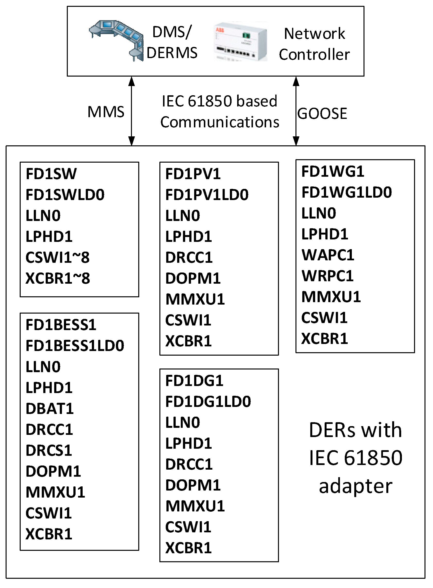
| Logical Node Name | Description | Standard |
|---|---|---|
| FD1SW | Switches adapter in the feeder 1 | Custom |
| CSWI | This LN class shall be used to control all switching conditions above process level | IEC 61850-7-4 |
| XCBR | This LN is used for modelling switches with short circuit breaking capability. | IEC 61850-7-4 |
| FD1PV1 | Photovoltaic (PV) DER adapter | Custom |
| DRCC | The DER supervisory control logical node defines the control actions for one DER unit or aggregations of one type of DER device with a single controller. | IEC 61850-7-420 |
| DOPM | This logical node provides settings for the operating mode at the electrical connection point. | IEC 61850-7-420 |
| MMXU | This LN shall be used for calculation of currents, voltages, powers and impedances in a three-phase system. | IEC 61850-7-4 |
| FD1WG1 | Wind generator DER adapter | Custom |
| WAPC | This logical node shall comprise the data classes that represent information concerning wind power plant active power control. | IEC 61400-25-2 |
| WRPC | This logical node shall comprise the data classes that represent information concerning wind power plant reactive power control. | IEC 61400-25-2 |
| FD2MCDG1 | Diesel generator adapter | Custom |
| FD2BESS1 | Battery energy storage system adapter | |
| DBAT | The DBAT logical node covers the battery system characteristics covered in the DBAT logical node reflect those required for remote monitoring and control of critical auxiliary battery system functions and states. | IEC 61850-7-420 |
| DRCS | The DER controller DRCS logical node defines the control status of one DER unit or aggregations of one type of DER device with a single controller. | IEC 61850-7-420 |
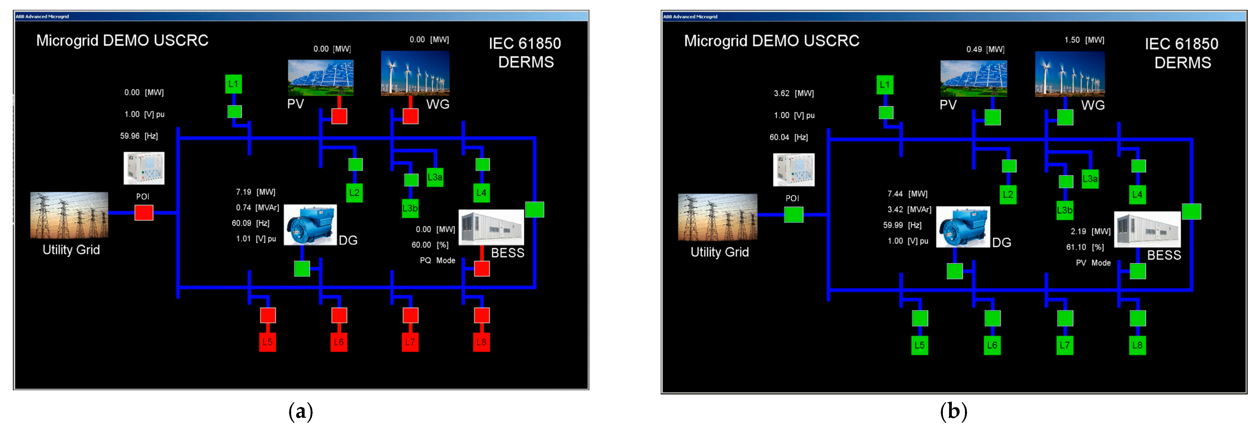
| 1 | The operator sends a close command to POI CB and microgrid is in grid connected mode and receives power from the utility grid as described in Figure 7. SBO command has been issued via SCSWI1.Pos in FD1SW adapter. Then the changed CB status is delivered via XCBR1.Pos.stVal. Please note that in order to show the communication possibility using the proposed adapter, synchronization is not performed in this scenario. |
| 2 | PV CB is closed via control command. |
| 3 | Wind DER CB is closed. The microgrid is supplying power to the utility grid since it is generating more power than its loads within microgrid. Please note that the transients are due to the absence of re-synchronization function between the microgrid and the wind DER in the simulation model. |
| 4 | BESS DER CB is closed. Once BESS is connected to the grid BESS is in charging mode and load flows direction is changed. Now utility grid is supplying power to the microgrid. |
| 5 | Load 8 CB is closed. |
| 6 | Load 5 and 6 CBs are closed. |
| 7 | Battery mode has been changed from charging to discharging. This can be monitored via DRCS1.ChaSt.stVal. |
| 8 | Load 7 CB is closed. |
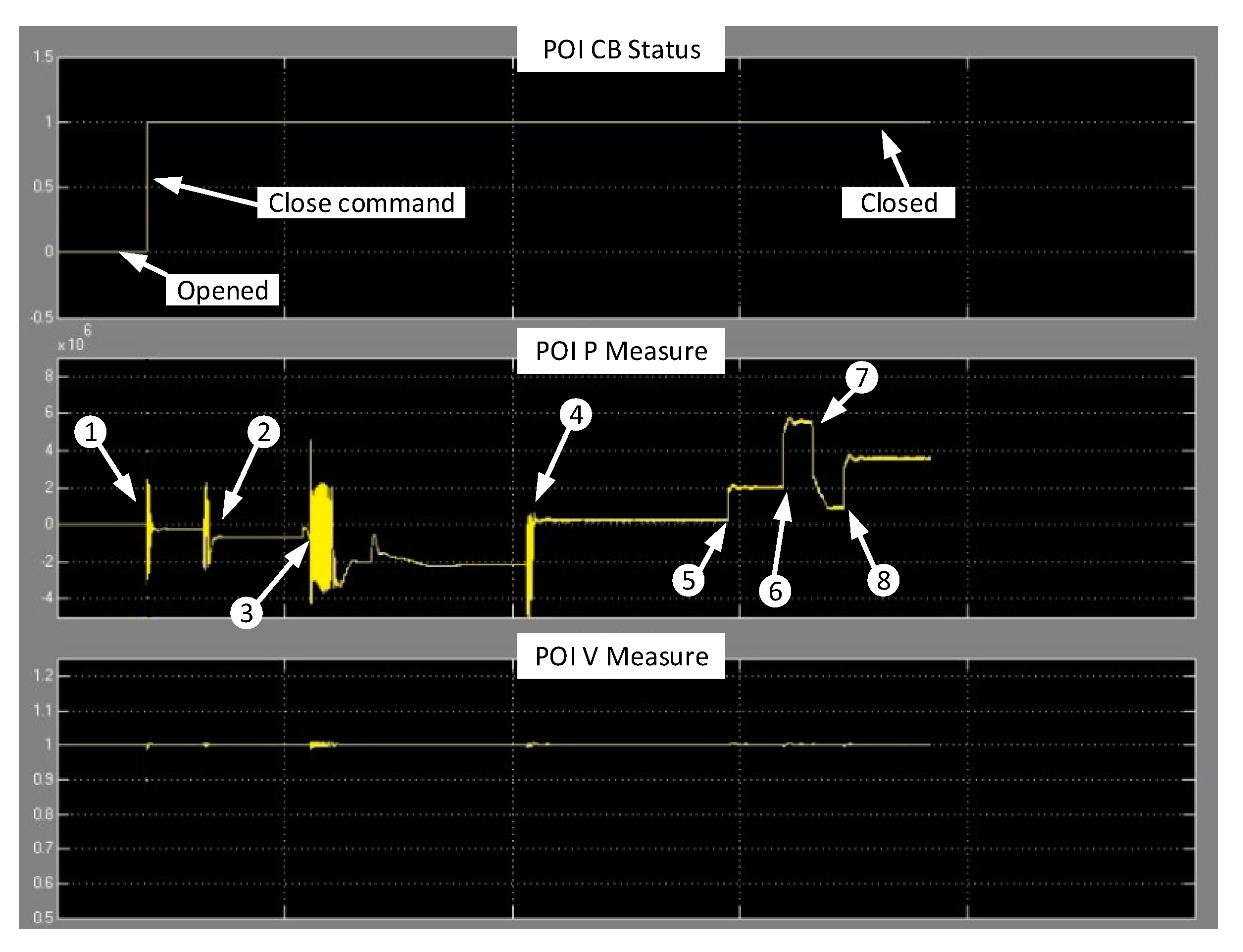
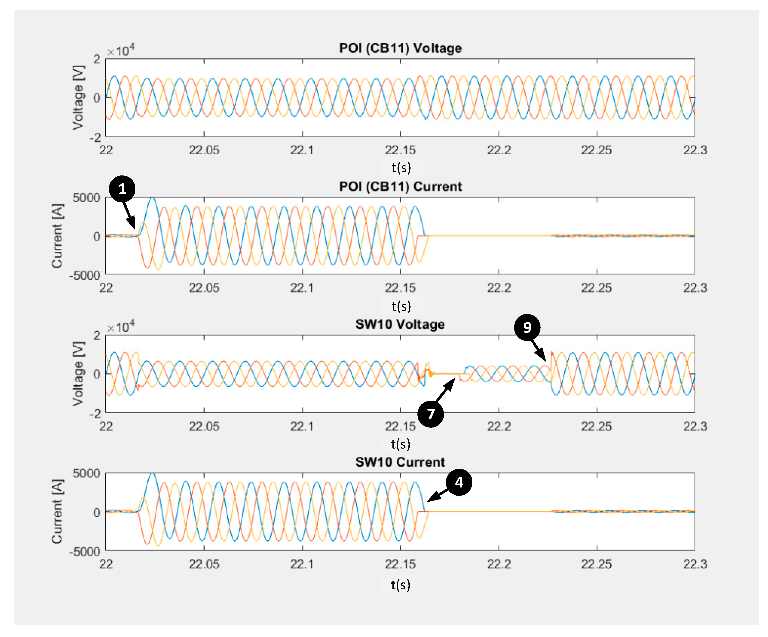
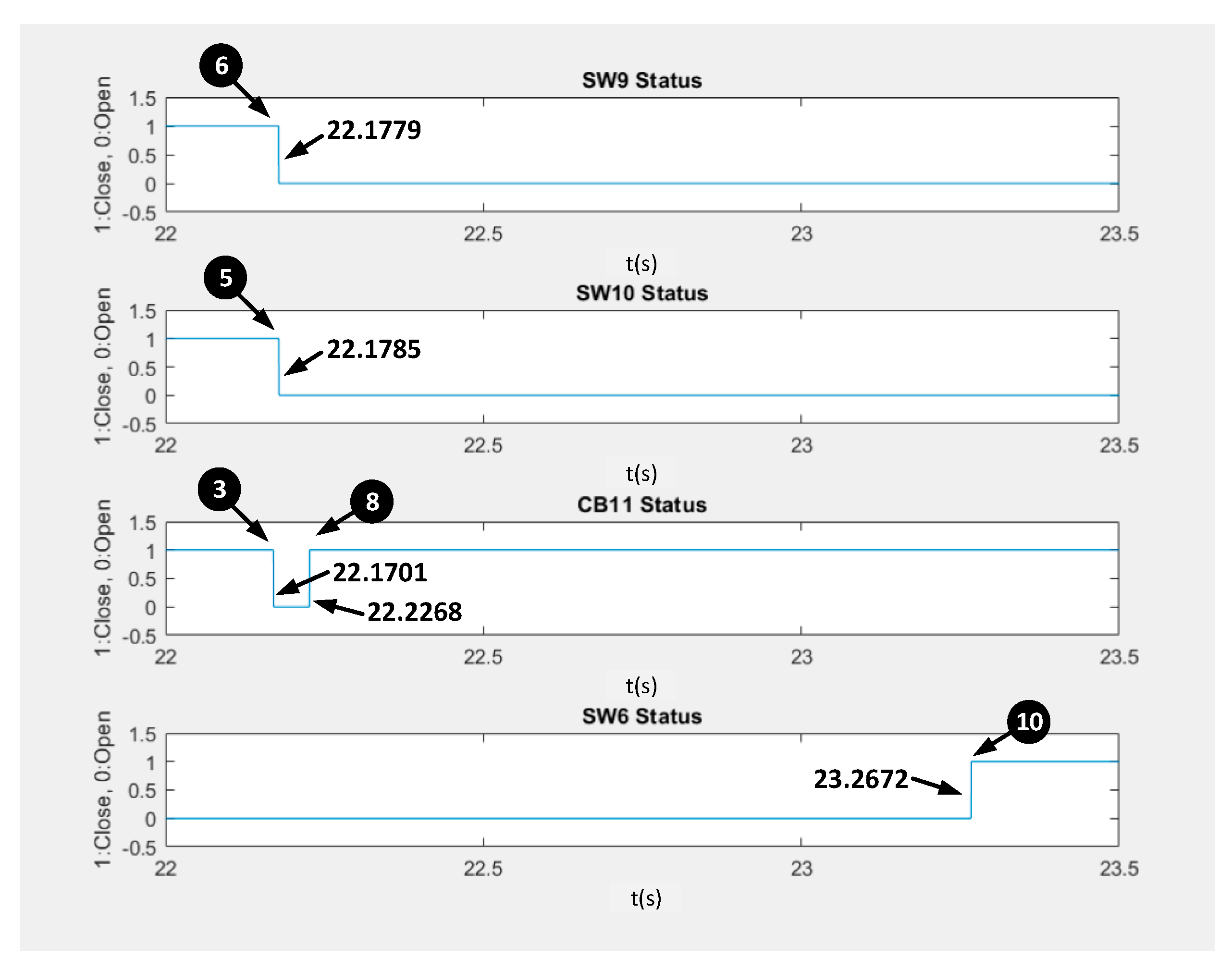
| 1 | Before this event, microgrids are operating normally as a grid connected mode. When a permanent three-phase to ground fault occurred at the section between SW9 and SW10, the subsystem 2 will experience the transient as shown in the Figure 8 (CB11 voltage and current graph). |
| 2 | The protective IED picks up the fault and sends a trip signal to CB11 in the subsystem 2 (the detailed packets have been shown in Figure 10). Then the switches in the subsystem 2 will report the and to the network controller 2 as described in Algorithm 1. |
| 3 | CB11 opened after receiving the switching control command from protective IED. |
| 4 | CB11 clears the fault. |
| 5 | The network controller calculates the faulted section based on Algorithm 2, and then sends switching commands to SW 9 and SW10. The SW10 is now opened. |
| 6 | SW 9 is now opened by the network controller 2. |
| 7 | The fault has been isolated by switching actions; however, the local DER keeps contributing the voltage. |
| 8 | The restoration process is started so the network controller 2 is closing CB11 and restore the healthy upstream section. |
| 9 | After restoring the upstream section, the sections from main utility grid to SW10 are now energized. |
| 10 | The network controller 2 is calculating whether the remaining DER can cover the remaining loads within the island. However, remaining loads are bigger than remaining DER, the network controller 2 and 1 are exchange the data to check whether subsystem 1 can cover the remaining healthy loads in subsystem 2 as illustrated in Algorithm 3. Then the network controller 2 transfers remaining loads to subsystem 1 by closing SW 6 as shown in Figure 8. |
| No. | Normal Scenario | Without Device Communication Failure Mitigation | With Device Communication Failure Mitigation |
|---|---|---|---|
| 1 | CB11 opened at 22.1701 s | CB11 opened at 22.1701 at 22.1701 s | CB11 opened at 22.1701 at 22.1701 s |
| 2 | SW9 opened at 22.1779 s | SW9 does not response | SW9 does not response |
| 3 | SW10 opened at 22.1785 s | SW10 opened at 22.1785 at 22.1785 s | SW10 opened at 22.1785 at 22.1785 s |
| 4 | - | - | Check heartbeat of SW9, 8 and CB 12 at 22.1799 s |
| 5 | -- | SW 8 and CB 12 opened at 22.1819 | |
| Total time | 8 ms | Fault detection and isolation process failed due to the communication failure | 12 ms (4 msec to find the available SW and CB) |
Publisher’s Note: MDPI stays neutral with regard to jurisdictional claims in published maps and institutional affiliations. |
© 2021 by the authors. Licensee MDPI, Basel, Switzerland. This article is an open access article distributed under the terms and conditions of the Creative Commons Attribution (CC BY) license (http://creativecommons.org/licenses/by/4.0/).
Share and Cite
Hong, J.; Ishchenko, D.; Kondabathini, A. Implementation of Resilient Self-Healing Microgrids with IEC 61850-Based Communications. Energies 2021, 14, 547. https://doi.org/10.3390/en14030547
Hong J, Ishchenko D, Kondabathini A. Implementation of Resilient Self-Healing Microgrids with IEC 61850-Based Communications. Energies. 2021; 14(3):547. https://doi.org/10.3390/en14030547
Chicago/Turabian StyleHong, Junho, Dmitry Ishchenko, and Anil Kondabathini. 2021. "Implementation of Resilient Self-Healing Microgrids with IEC 61850-Based Communications" Energies 14, no. 3: 547. https://doi.org/10.3390/en14030547
APA StyleHong, J., Ishchenko, D., & Kondabathini, A. (2021). Implementation of Resilient Self-Healing Microgrids with IEC 61850-Based Communications. Energies, 14(3), 547. https://doi.org/10.3390/en14030547