Article

Design and Optimization of a Radial Inflow Turbine for Use with a Low Temperature ORC

1
School of Mechanical, Medical & Process Engineering, Queensland University of Technology (QUT), Brisbane City, QLD 4000, Australia
2
Laboratoire d’Ingénierie des Fluides et des Systèmes Energétiques (LIFSE), Arts et Metiers Institute of Technology, Conservatoire National des Arts et Métiers (CNAM), Hautes Écoles Sorbonne Arts et Métiers (HESAM) Université, F-75013 Paris, France
*
Authors to whom correspondence should be addressed.
Energies 2021, 14(24), 8526; https://doi.org/10.3390/en14248526
Submission received: 29 October 2021 / Revised: 30 November 2021 / Accepted: 6 December 2021 / Published: 17 December 2021
(This article belongs to the Special Issue Turbomachinery, Energy and Environmental Technologies)

Abstract

:
This study aims to design and optimize an organic Rankine cycle (ORC) and radial inflow turbine to recover waste heat from a polymer exchange membrane (PEM) fuel cell. ORCs can take advantage of low-quality waste heat sources. Developments in this area have seen previously unusable, small waste heat sources become available for exploitation. Hydrogen PEM fuel cells operate at low temperatures (70 °C) and are in used in a range of applications, for example, as a balancing or backup power source in renewable hydrogen plants. The efficiency of an ORC is significantly affected by the source temperature and the efficiency of the expander. In this case, a radial inflow turbine was selected due to the high efficiency in ORCs with high density fluids. Small scale radial inflow turbines are of particular interest for improving the efficiency of small-scale low temperature cycles. Turbines generally have higher efficiency than positive displacement expanders, which are typically used. In this study, the turbine design from the mean-line analysis is also validated against the computational fluid dynamic (CFD) simulations conducted on the optimized machine. For the fuel cell investigated in this study, with a 5 kW electrical output, a potential additional 0.7 kW could be generated through the use of the ORC. The ORC’s output represents a possible 14% increase in performance over the fuel cell without waste heat recovery (WHR).

1. Introduction

As the use of hydrogen for the storage and generation of electricity increases, new innovative methods to increase the efficiency of conversion between hydrogen gas and electricity will be needed. The ITP Energised group’s report, prepared for the Australian government [1] on dispatchable energy options, concludes that hydrogen will likely be an important part of the zero-carbon energy storage mix. Hydrogen was found to be cost effective for long term and strategic energy reserves due to its low cost of storage in natural or artificial caves [1]. The report highlights that the current problems with hydrogen are the very high costs of electrolysis and fuel cells for the conversion of hydrogen to electricity and electricity to hydrogen, respectively. While the costs of fuel cells are falling [2], they are still more expensive than conventional generation methods [3]. In the literature, many avenues are being investigated to decrease the cost of fuel cells, including developing low-cost catalyst material to replace platinum [4], optimizing fuel cell use to decrease internal losses, increasing current fuel cell efficiency [5], and increasing the operational life of fuel cells [6].
This study will focus on adapting waste heat recovery (WHR) methods that have been proven to work in applications such as fossil fuel plants [7,8,9] to a low temperature hydrogen fuel cell. WHR is used to recover heat that would otherwise be wasted, boosting the plants overall efficiency by using a secondary, bottoming thermodynamic cycle to generate extra power. Research has shown that, by optimizing both an organic Rankine cycle (ORC) and expander for a given power output and temperature, an effective system can be created [10,11]. The proposed study aims to apply this methodology to polymer exchange membrane (PEM) fuel cells and investigate the available gains. Some works have considered WHR as a method to improve PEM fuel cells system efficiency by generating auxiliary power [12,13]; however, they have assumed a constant expander efficiency. This work aims to show not only that an ORC system can be designed to take advantage of the waste heat from a PEM fuel cell but also that an efficient expander can be designed for the selected fluid, operating conditions, and power output.
An ORC has been chosen as the thermodynamic cycle over other options such as flash cycles and Stirling cycles. ORCs have been widely studied for low temperature applications [14,15,16,17,18] and have high efficiency compared to other thermodynamic cycles [19]. ORCs can also operate with dry expansion (where the expansion occurs entirely as either saturated or superheated gas), which will allow the use of micro turbines [20]. Research into ORCs mostly focuses on temperature sources above 100 °C [20], as higher temperature sources allow for efficient generation of electricity. Lower temperature systems are possible; Park et al. [21] reviewed experimental studies of ORCs and found testing at temperatures as low as 45 °C. However, from the 58 experimental tests reviewed by Park et al. [21], only 15 had source temperatures below 100 °C and only two below 70 °C.
Forman et al. [22] estimated the global waste heat potential at 245 PJ, with 63% of this energy below 100 °C and 79% below 200 °C. From this, it is clear that low temperature waste heat could be a significant source of energy if it can be effectively exploited. For this reason, low temperature ORCs are currently the focus of much research [23,24]. Astolfi et al. [23] optimized a cycle for the exploitation of low temperature geothermal resources based on the cost per watt of the cycle and the geothermal wells. They found that the optimal cycle and the fluid changed based on the geothermal well temperatures. At high temperatures (180 °C), a supercritical cycle with a regenerative heat exchanger was the most efficient, while at low temperatures (120 °C) the most efficient cycle was a subcritical superheated cycle. Öhman [24] investigated the use of ammonia in low temperature cycles. Their aim was to recover heat from a pulp mill (initial wood to pre-paper refinement) at 75–85 °C. The ORC was designed as a replacement for the current cooling solution, and their experimental testing resulted in a thermodynamic efficiency of 8.3%. They concluded that the payback period would be around three years, although this includes the ‘green certificates’ available in Sweden for the cost of electricity. As fossil fuel based thermal plants are being phased out, a significant market for low temperature ORCs has opened as a potential solution to green power generation [25].
Low temperature cycles are generally limited by the Carnot efficiency:
η = 1 T C o l d T H o t .
Thus, at lower temperatures, the recovery becomes less efficient. With improved turbine performances and lower manufacturing costs, lower temperature sources become economical despite lower overall cycle efficiency [26]. While the initial cost, cost per Watt, and size of the WHR system is important, it requires detailed information of all components of the ORC. This study focuses on the design of a radial inflow turbine under operating conditions in a WHR cycle. The efficiency and the amount of power generated are important when considering if reasonable cycles can be designed before conducting an in-depth economic analysis. As the heat input is fixed (11 kW) in this study, the efficiency of the cycle is directly proportional to the power generated. This study thus focuses on the efficiency and power generation of the ORC and the efficiency of the expander; future work will be required to design and optimize heat exchangers and pumps for the ORC that would enable an economic and a cost-benefit analysis for various designs before the system is implemented.
Bao and Zhao [20] reviewed the isentropic efficiency of expanders used in ORCs; the most popular expanders were scroll expanders and radial inflow turbines. Radial inflow turbines are used in larger scale plants generally with an output power over 1 kW. Scroll expanders are commonly used in smaller cycles with powers in the range of 0.2–3 kW. Scroll expanders generally have lower efficiencies, in the range of 65–80% [20], while radial inflow turbines generally have an efficiency of around 70–85% [20]. Other expanders, such as rotary vane expanders and piston expanders, normally exhibit low efficiencies and are used less often [20]. In this study, a radial inflow turbine was chosen as the expander due to its higher isentropic efficiency.

2. Scenario Configuration

PEM fuel cells have very high efficiency, operate at low temperatures, and can quickly vary their output to match demand [27], which makes them a popular means for converting hydrogen to electricity. Due to its high efficiency, it was chosen as the base load supply in a pilot green hydrogen plant commissioned at the Queensland University of Technology, Brisbane, Australia. The chosen cell is a PS5 from Powercell (South Australia, Australia), which will run close to its maximum power output of 5 kW. This will generate approximately 11 kW of heat [28]. As its planned usage is as a baseload supply, the power output will be constant for long periods. For this analysis, the heat output of the cell was assumed to be constant. The fuel cell’s coolant outlet temperature was fixed to 70 °C from the manufacturer’s minimum cooling recommendations [28]. Increasing this temperature could improve the ORC performance; however, if the fuel cell performance were to suffer from operating outside its recommended temperature range, then potential gains from a WHR cycle could be insignificant comparatively. For this reason, the inlet temperature was set as the maximum temperature recommended for the fuel cell. From literature, the performance of fuel cells tends to increase as temperature increases [27,29]. However, if the humidification of the membrane cannot be maintained at this temperature, then the performance quickly decreases due to the increase in membrane resistance [30].
The heat source of the ORC proposed in this paper is setup as a closed system with the PEM fuel cell coolant flowing from the fuel cell through the ORC’s hot side heat exchanger and flowing back into the fuel cell, as seen in Figure 1. In this case, the heat removed from the coolant is equal to the heat input from the fuel cell. In a larger system it may be necessary to have a secondary heat exchanger that dissipates heat if the ORC were to fail, needs to be taken offline, or is unable to cope with varying demand. However, to generate the greatest amount of power, all heat energy should be used in the ORC. Consequently, a secondary heat exchanger was not considered for this analysis.

3. Methodology

The methodology is split into three sections. First, the ORC is optimized using fixed turbine efficiency. Second, the ORC’s operating parameters are used to optimize the design of the radial inflow turbine. The turbine total to static isentropic efficiency is then used to re-optimize the ORC. This process is iterated until the design of the ORC and turbine have converged. Finally, the design of the turbine is validated using CFD to confirm the turbine efficiency as seen in Figure 2.

3.1. Organic Rankine Cycle

The cycle chosen for the WHR was a subcritical ORC with superheating due to its high efficiency in low temperature applications [19,23]. This cycle has seven thermodynamic processes that define the cycle, as listed below:
  • Isentropic pressure increase—pressure increase with fixed isentropic efficiency of 60%;
  • Isobaric heating—heating in the liquid phase;
  • Isobaric heating—evaporation of the working fluid;
  • Isobaric heating—superheating the working fluid in the gas phase;
  • Isentropic pressure decrease—pressure decrease with the turbine’s total to static isentropic efficiency;
  • Isobaric cooling—cooling of the working fluid in the gas phase;
  • Isobaric cooling—condensation of the working fluid.
The pressure is increased (1) by the working fluid pump with work input into the cycle, then the isobaric heating (2–4) occurs in the hot side heat exchanger, the working fluid is then expanded through the turbine (5) where work is generated, and it is finally cooled (6–7) by the cold side heat exchanger before returning to the pump inlet (Figure 1). For each thermodynamic process, the working fluid properties were calculated using CoolProp [31] by bell et al. To avoid the impact of liquid droplets causing structural damage to the fast-moving blades of the expander, the design of the ORC was carefully considered to ensure dry vapor through the entire expansion process. The mass flow rate for the ORC working fluid was calculated using the heat input of 11 kW from the fuel cell.
The fuel cell cooling cycle was modeled as a closed system; therefore, the ORC was used to completely remove the heat generated by the fuel cell. As the coolant exits the fuel cell, it enters the ORC heat exchanger, where 11 kW of heat is transferred to the working fluid. The coolant is then pumped back into the fuel cell, cooling the fuel cell absorbing the 11 kW of heat energy. As the cooling loop is closed, if not enough energy is absorbed from the coolant by the ORC’s working fluid, then the coolant temperature would rise increasing the temperature difference across the heat exchanger and thus increasing the heat flow. The heat exchanger was assumed to be designed so that 11 kW of heat is transferred with a pinch point temperature of 5 °C, as in the work by Cataldo [32]. Assuming that the pinch point temperature is useful, no information about the heat exchanger design is required. This allows for a quick calculation of fluids temperatures on each side of the heat exchanger, without detailed design or calculation of a convective heat transfer coefficient at multiple points in the heat exchanger, which can be computationally expensive. The amount 5 °C was used as the pinch point temperature to achieve a balance between heat exchanger size and performance. Ashouri et al. [33] investigated heat exchanger performance in detail for a solar ORC power station and found that reduction in the pinch point temperature increased the performance and the performance per cost across the range tested (4–9 °C). As basic heat exchanger assumptions were used, the pressure drop and heat lost to the environment could not be calculated, thus, it was assumed there was no loss of heat to the environment [12,33,34,35] and no pressure drop through the heat exchangers [12,32,34,35,36,37]. These assumptions are consistent with other works optimizing ORCs; however, these assumptions should be tested in future works through a detailed heat exchanger design and optimization and an economic optimization performed similar to work presented in Lecompte et al. [38].
An initial study was conducted using a fixed turbine efficiency of 80% for the expander, from which cyclopentane was selected as the working fluid. By using cyclopentane, a more detailed analysis of the cycle and turbine was conducted. An optimization was then performed using the super heating temperature, heating fluid mass flow rate, and cooling fluid flow rate as parameters for optimization.
Cyclopentane was chosen as the working fluid due to it high efficiency, zero ozone depletion potential (ODP), very low global warming potential (GWP) (<0.0001), low toxicity [39], and preferable cycle pressures at the ORC operating temperatures (Table 1).
The low absolute pressure difference between the evaporator and condenser (101 kPa) means the pump power usage was lower. The low pressure also increased the size of the turbine as the low pressure reduced the density of the fluid. In most cases, a more compact turbine is preferable, but due to its small size and low power, some problems associated with very small designs can be avoided through a lower pressure fluid. In most cases, small turbines run with very high rotational speeds, and denser fluids will reduce the size of the turbine further [26].
Tocci et al. stated that, in general, high pressures should be avoided, as the cycle requires thicker heat exchanger walls and stronger materials, increasing cost [26]. They also stated that pressures below 50 kPa should be avoided, as these increase sealing costs [26]. Cyclopentane is within the preferable range, although sealing will need to be considered, as it operates close to 50 kPa in the condenser.

3.2. Meanline Design

The pressure ratio, inlet pressure, and temperature all affect the expanders performance, and its performance affects the optimal ORC efficiency. A more accurate assessment of the expander efficiency is required to better assess the cycle’s performance, and a mean-line model is required for this assessment.
The mean-line turbine design was conducted by solving the following equations based on the Euler turbine equation and the definitions of the non-dimensional values for turbines, as given by Schobeiri [40].
ϕ = 1 tan ( α 3   ) tan ( β 3 )
v μ ϕ = ( tan ( α 2 ) tan ( β 2 ) )
λ = ϕ ( μ × v × tan ( α 2 ) tan ( β 3 ) ) 1
r = 1 + ϕ 2 2 ( 1 + tan ( α 3 ) 2 μ 2 ( 1 + tan ( α 2 ) 2 ) ) λ .  
For any five of the values, flow coefficient ( ϕ ), meridional velocity ratio ( μ ), degree of reaction ( r ), radius ratio ( v ), rotor inlet and outlet absolute flow angles ( α 2 , α 3 ), and rotor inlet and outlet relative flow angles ( β 2 ,   β 3 ) can be selected to solve for the remaining four. The five values are generally selected by optimization or through empirical correlations for turbine performance. In this case, v , α 2 , α 3 , β 2   and   β 3 were used as the inputs for optimization, along with the rotor rotational velocity. From the non-dimensional values, rotor rotational velocity, and operating point information from the ORC cycle, the turbine geometry can be calculated as well as the approximate blade angles, as presented in Figure 2. Each velocity triangle can be calculated from the non-dimensional value definitions, the blade heights from the density and flow velocity, and the rotor diameter from the blade tip speed and rotor angular velocity.
To calculate the geometry of the turbine more accurately, empirical equations are used to estimate the difference between the blade angle and the flow angle. At the stator exit, the equation recommended by Suhrmann et al. [41] was used, which provides the difference between the rotor blade inlet angle and the flow angle. This new flow angle was then used to adjust the stator outlet angle to achieve the correct absolute rotor inlet flow angle. At the rotor outlet, another equation developed by Suhrmann et al. [41] was used to adjust the rotor outlet blade angle so that the relative outlet flow angle was in line with the mean-line design.
The initial calculation of the turbine geometry assumes an isentropic turbine flow, then loss models are used to calculate the enthalpy loss. From the losses, the efficiency is recalculated for the next iteration until the efficiency of the design has converged. The losses considered in the mean-line model were rotor passage loss from Glassman [42], which combines both secondary and frictional effects; Colebrook friction factor without rotor correction factors from Suhrmann et al. [41] for the stator blades; windage loss from Cho et al. [43]; tip losses from Rodgers and Geiser [44]; the average hydraulic diameter of the turbine passage from Deng et al. [45]. Once the initial losses are calculated, the geometry is recalculated, taking into consideration the new enthalpy drop in the turbine. This process is iterated until the geometry has converged. This process (Figure 2) produces a turbine geometry based on the input parameter values selected by the optimization function and its associated efficiency.
The pressure ratio, inlet pressure, temperature, and mass flow were fixed as the values from the ORC modeling. The design of the turbine was determined through the dual annealing global optimization available in the Scypi module for Python [46], using five of the non-dimensional values ( v , α 2 , α 3 , β 2   and   β 3 ) and the rotational velocity. The design of the turbine was optimized for the highest total to static efficiency; this efficiency was then used in the ORC code to reoptimize the cycle, given the new calculated expansion efficiency, until both the optimal cycle and turbine design had converged.

4. Validation

Each section of the analysis was validated by comparing the results to published works that investigated similar problems. This step allowed for the testing of the accuracy of the correlations used so that the solutions produced were deemed accurate.

4.1. ORC Validation

The ORC was validated using values given by Zhao et al. [13], who provide temperature and pressure for a range of fluids and the resultant thermodynamic efficiency for each in an ORC operating between 353.15 K and 298.0 K. As seen in Table 2, the error between the efficiency using current models and the results from Zhao et al. were small with a maximum error of 0.21%. The small error between the work by Zhao et al. [13] and the current work was due to minor differences in fluid properties between CoolProp (used in this work) and REFPROP by NIST, Gaithersburg, USA (used by Zhao et al. [13]).

4.2. Mean-Line Validation

To validate the mean-line model, four previous works were used as reference cases: Jones [47], Glassman [42], Do-Yeop [48], and Ayad [49]. Jones and Glassman were chosen because they are popular mean-line validation cases, although they used air and argon respectively, which behave like ideal gases. Ayad and Do-Yeop both designed turbines for use with a high-density refrigerant that operated close to their saturation curves. Both papers also conducted CFD to verify their solutions. The results are presented in Table 3.
The error between these cases and the current mean-line model is low around 3%. The proposed model uses the same radius ratio and blade angles as the reference cases to validate the loss models used. The error is higher for the cases with high density gases likely as loss models are mainly based on air as the working fluid and do not account for the varied properties of high-density fluids.

4.3. Validation for Optimized Case

The optimization was then run for the Do-Yeop [48] case with the input parameters listed in Table 4.
As Do-Yeop [48] optimized the design of their turbine, the result of the optimizations should be similar if both had reached global maximum efficiency for the design. The optimization space allowed angles α 2 and β 3 from −180° to 180°.
The optimization results for the flow angles of the optimal turbine are presented in Table 5. The final optimized solution was verified using CFD, resulting in a T-S (total-to-static) efficiency of 85.72%, demonstrating that the mean-line model was accurate and achieved a highly efficient solution.

5. Results

5.1. Optimized ORC for PEM Fuel Cell with Optimized Turbine

To optimize the ORC for the PEM fuel cell, both the ORC and the turbine were optimized. The final ORC design for heat recovery from a fuel cell is presented in Table 6.
The result of the optimized ORC had a higher cold fluid flow rate than hot flow rate. As the majority of the heat transfer out of the working fluid occurred isothermally during condensation, the increase in flow rate could significantly decrease the minimum temperature of the cycle, increasing the efficiency. More heat transfer into the cycle occurred during the liquid and gas phase of the working fluid, so a lower flow rate could be used while maintaining a high maximum cycle temperature.
The optimization bounds were set so that the maximum flow rate was 10 kg/s; however, this could result in a significant pressure drop through a heat exchanger (depending on the design), which was not considered in this study. A much lower cold fluid flow rate could be used in a similar cycle with a cold fluid flow rate of approximately 2.1 kg/s. This would slightly decrease performance by 0.24% (to 7.33% thermal efficiency). A more detailed analysis of the heat exchangers would be required to determine the optimal point for performance and fluid pump requirements. While the design of the heat exchangers was not considered in this paper, the heat exchanger effectiveness was calculated using Equation (6) [50].
ε = Q ˙ a c t u a l Q ˙ m a x i m u m = Q ˙ a c t u a l ( m ˙ C p ) m i n   ( T h o t ,   i n T c o l d ,   i n ) .
Q ˙ a c t u a l is the transferred heat within the heat exchanger, ( m ˙ C p ) m i n is the mass flow specific heat with the lowest values for the fluids in the heat exchanger, and T h o t ,   i n and T c o l d ,   i n are the inlet temperatures for the hot and cold fluids, respectively [50]. The hot and cold heat exchangers for the ORC had an effectiveness ( ε ) of 0.52 and 0.55, respectively. Shah and Sekulić [50] noted that there was a large variance in the effectiveness of heat exchangers, depending on the application; however, they provided illustrative values of 63% for steam plant condensers, 98% for a sterling engine regenerator, and 99% for regenerators in LNG (liquefied natural gas) plants. From this wide range, the proposed design of the heat exchangers seemed reasonable, and the pinch point temperature could potentially be lowered if economically feasible.

5.2. CFD Results

The CFD analysis of the optimized turbine was then performed.
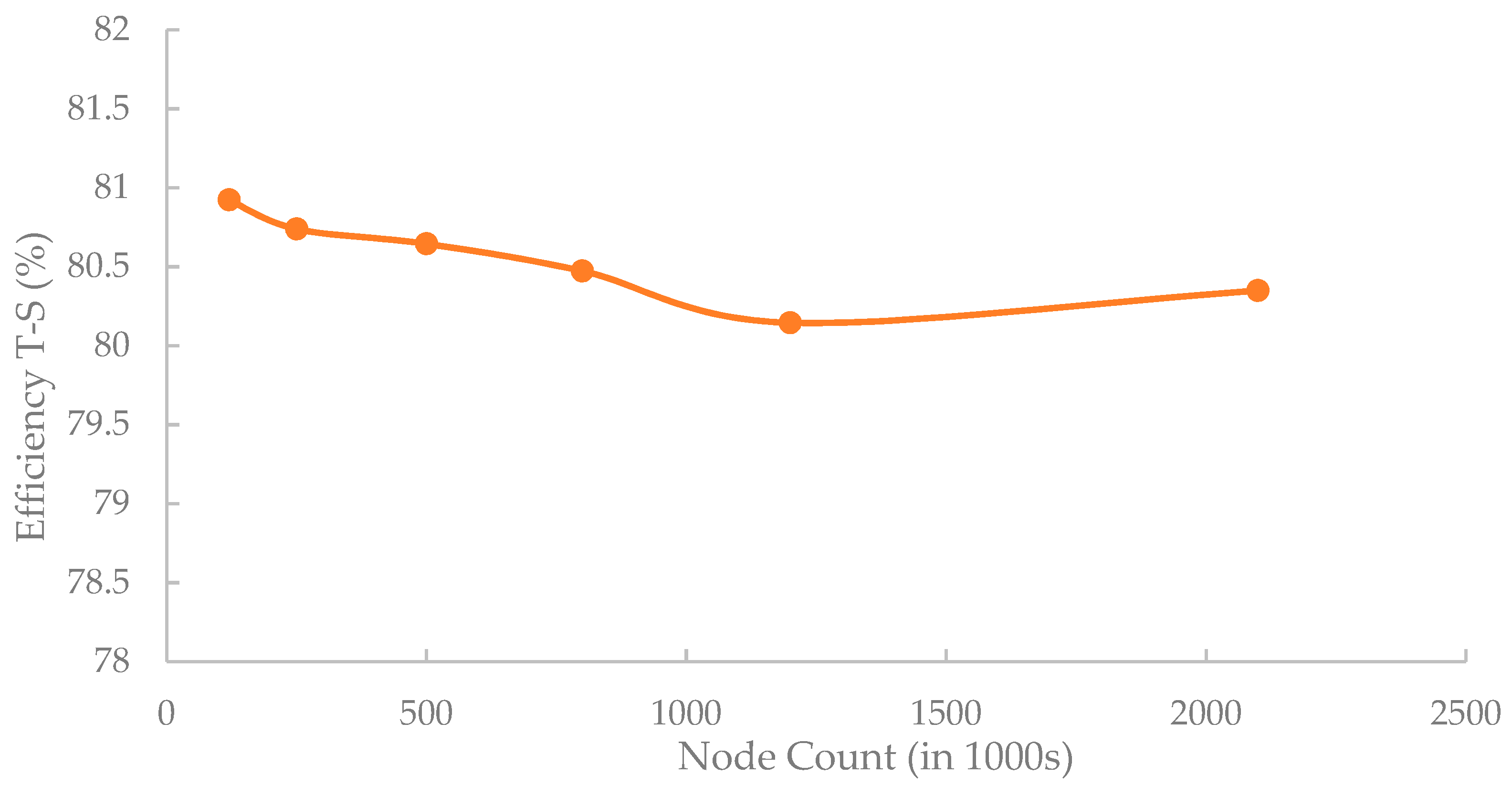
The mesh refinement in Figure 3 shows that using 1.2 M nodes will achieve mesh independence, so this was used for all simulations. The average Y+ for the rotor blade with 1.2 M nodes was 16.2 along the rotor blades.

5.3. Comparison Mean-line-CFD

The optimized turbine design is presented in Table 7. There was a significant gain in ORC performance between using the fixed efficiency (80%) and the final ORC with the mean-line turbine design. The cycle efficiency had improved from 6.8% to 7.5%, a relative improvement of approximately 10%. The CFD-simulated efficiency was 9.22% lower than the mean-line predictions.
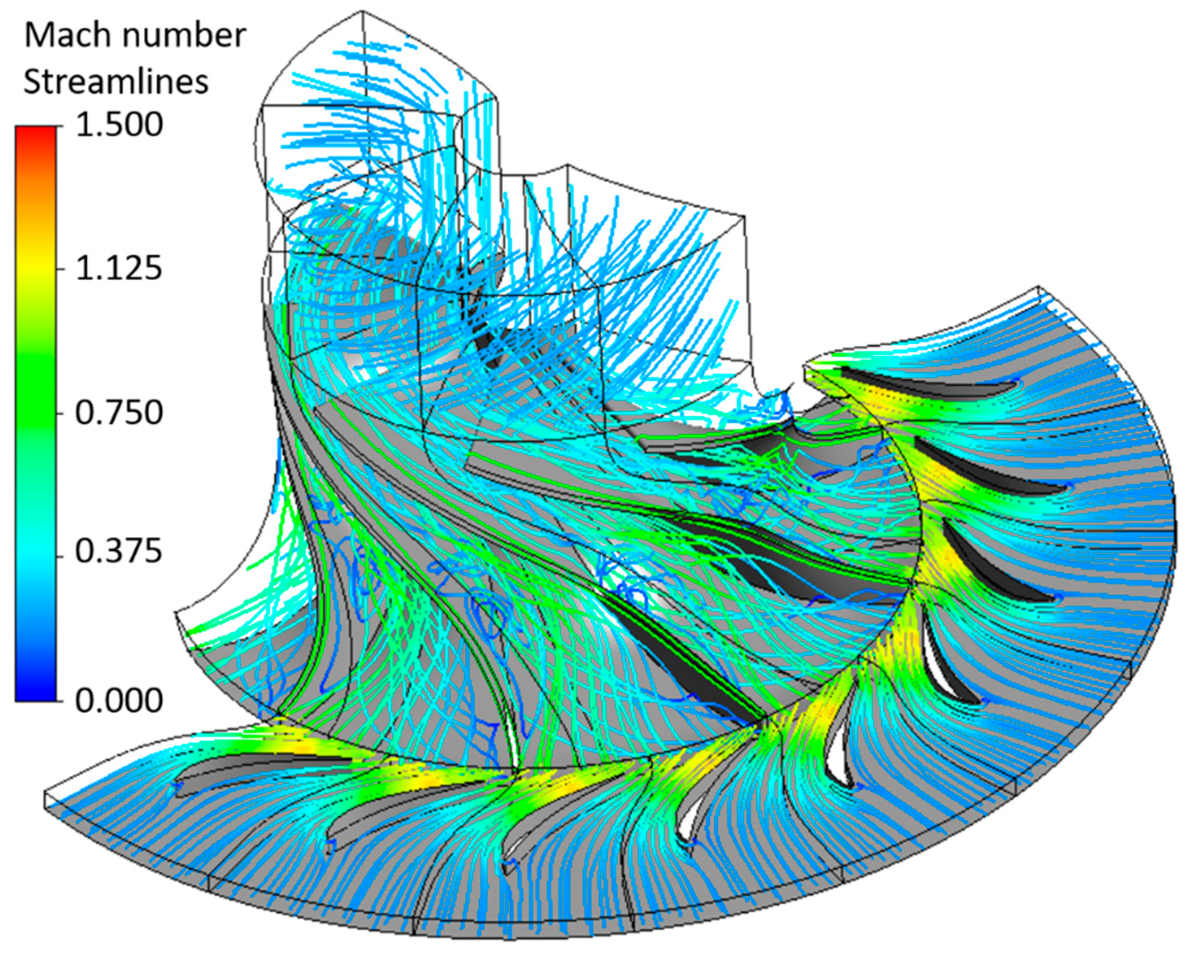
The large error between the mean line and CFD efficiencies was due to the chaotic swirling flows on the pressure side of the rotor blades and a large stagnation region on the suction side, as seen in Figure 4. These secondary flows would account for much of the increase in losses over the mean-line prediction. Capata and Sciubba [51] investigated the performance of low Reynolds number turbines, and they concluded that the highest efficiency shifted towards lower specific speeds and diameters than the Balji plots suggest. The calculated specific speed and diameter for this work’s design agreed well with Capata and Sciubba’s [51] prediction for peak efficiency at low Reynolds numbers, suggesting that the optimization had achieved an optimal design.
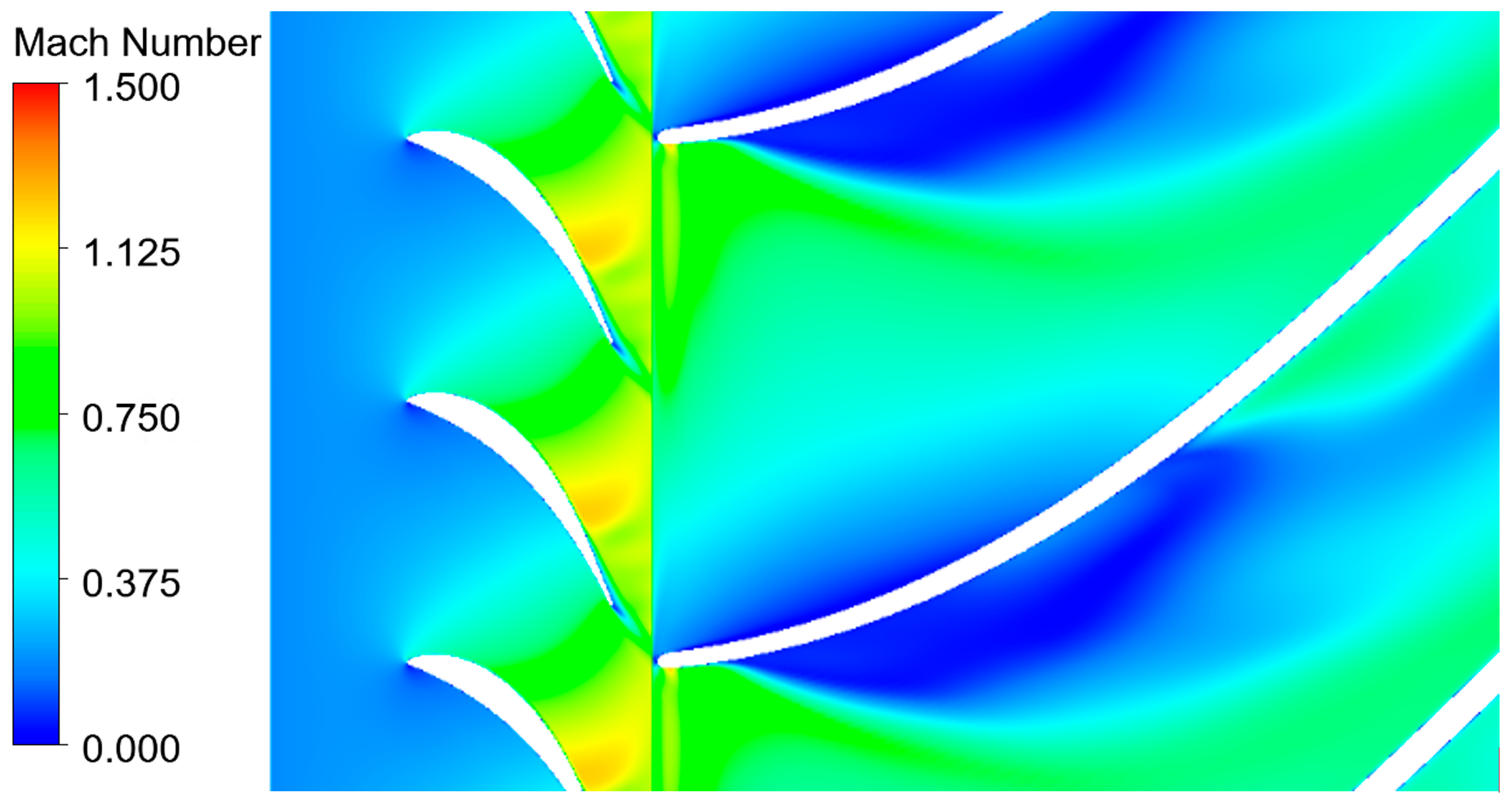
Looking at the blade-to-blade view (Figure 5), there is a supersonic region (yellow) as the flow curves around the leading edge of the rotor blade, followed by a large separation region (blue).
Due to the curvature of the blade, the stagnation region expanded, affecting the flow in the rest of the passage. The pressure side fluid then flowed around the circumference of the passage and caused the separation region to mix into the main flow, again causing the swirling flows seen in Figure 4. The mixing of the slow-moving separated region into the main flow resulted in significant entropy generation, which decreased the turbine efficiency.
The blade pressure loading profile (Figure 6) shows a rapid decrease in pressure on the suction side of the blade as the flow accelerated around the tip of the blade, the pressure then increased as the flow separated, dissipating much of the flow’s energy as heat.
As only the mean-line turbine had been optimized in this study, it is likely that with an optimized 3D blade design, the flow separation could reduce or be avoided entirely. A design that reduces the acceleration of the flow, stopping the flow locally reaching Mach 1 and less blade curvature initially, may reduce the size of the separation region and could substantially improve the flow and increase efficiency.

5.4. Design Point Analysis

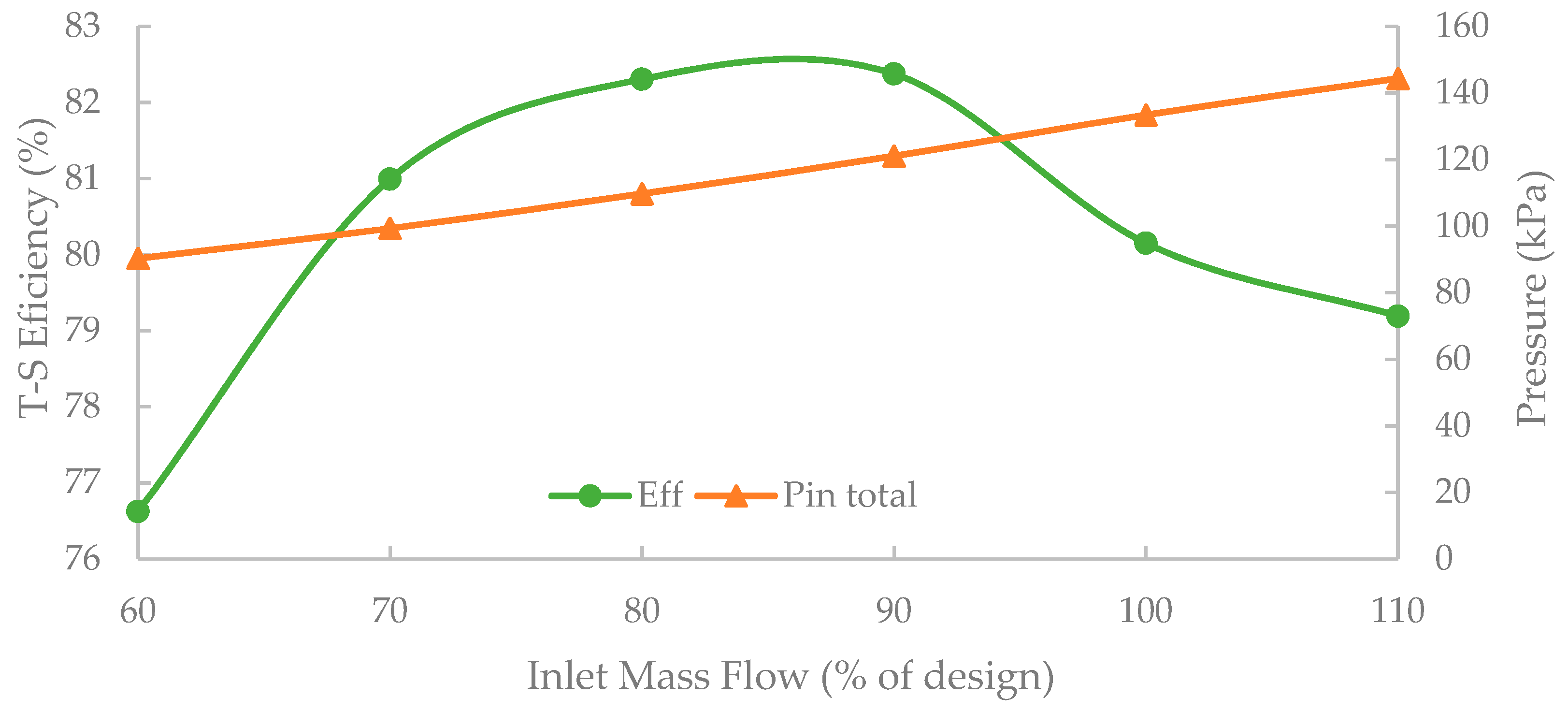
A set of simulations was run to assess the turbine performance at varying inlet mass flow rates (Figure 7).
From Figure 7, the maximum T-S efficiency lies between 80% and 90% of the design mass flow.
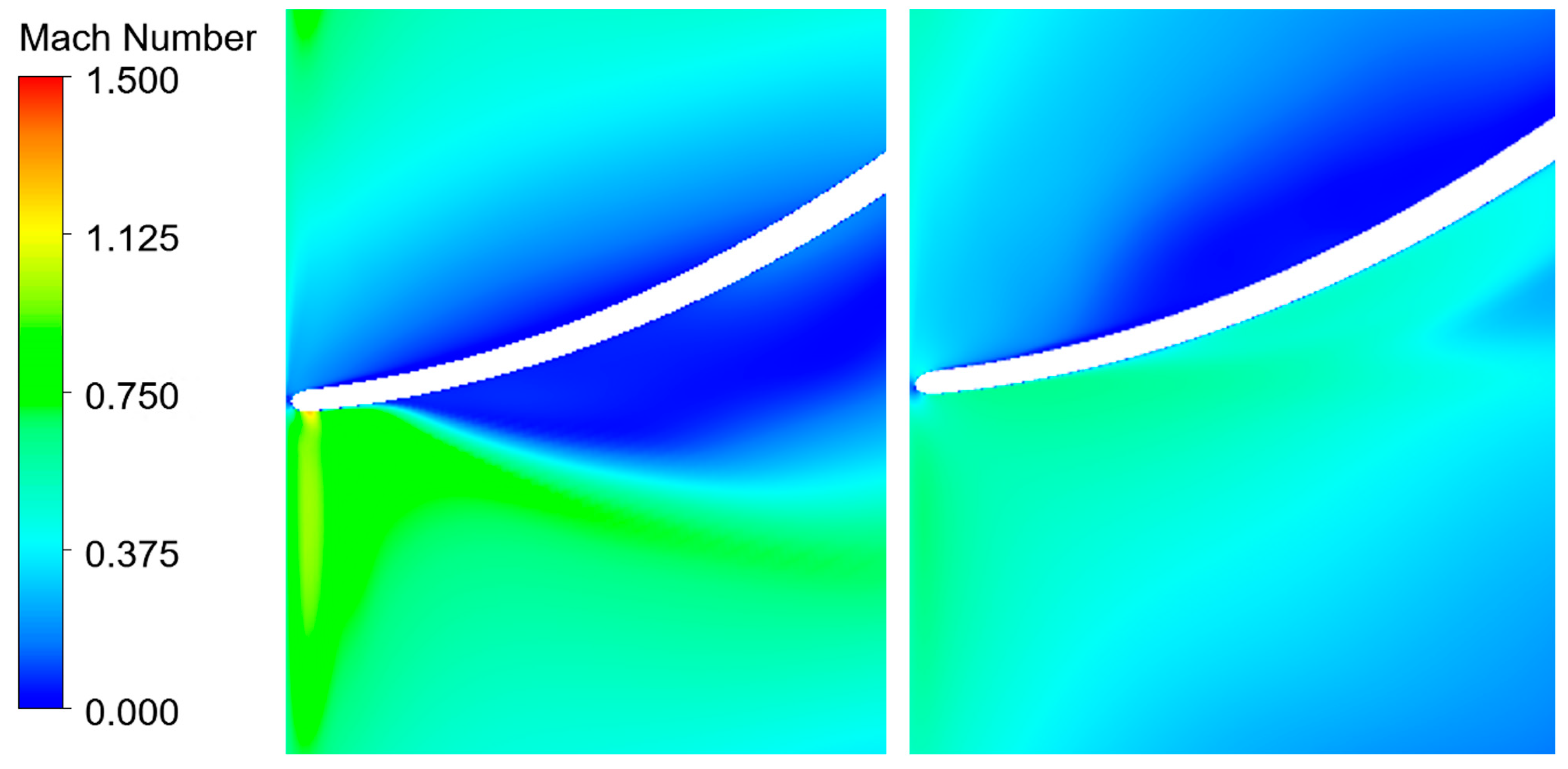
As seen in Figure 8, at higher flow rates, β 2 (inlet relative flow angle) was better aligned with the blade (0.98°). At 100%, there was an incidence angle of 10.9° between the flow and the blade. The misalignment between the mean-line and CFD flow angles was due to the lower inlet pressure predicted in the CFD (Figure 8). The lower pressure would increase the volume flow rate of gas, affecting flow velocities ( V 2 , V 3 ) and the relative flow angles ( β 2 , β 3 ) . At 70% mass flow, the tangential velocity at the rotor inlet was reduced, thus creating a greater incidence angle between the flow and the blade of 31.73° so that larger incidence losses occur. In Figure 9, the 70% mass flow rate has eliminated the separation on the suction side of the blade; however, secondary effects on the pressure side of the blade increased at low mass flows, as seen by the larger area of low velocity compared to 100%. The lower flow rates reduced the locally supersonic flow on the tip of the rotor blades on the pressure side, which was completely subsonic at 70% mass flow.
By varying the mass flow rate of the working fluid in the turbine, some of the secondary flow effects were reduced. Further optimization of the blade and shroud shapes could enable further gains in performance and should be considered in future work.

6. Conclusions

This study investigated the use of an ORC for the recovery of heat from a PEM fuel cell. It used a WHR cycle design methodology and applied it to the low temperature heat energy in the fuel cell coolant. The mean-line design of the radial inflow turbine for the designed ORC showed very high efficiency (89.4%). The CFD analysis of the design resulted in a lower but still high efficiency of (80.15%) with further optimization of the 3D geometry, allowing for the increase of the expansion efficiency towards the mean-line result.
With the optimized mean-line turbine, the energy recovered from the waste heat of the fuel cell would be around 0.836 kW through the corresponding ORC. Given the lower predicted turbine efficiency from the CFD, the actual output would be closer to 0.745 kW shaft power, resulting in a second law efficiency of 65.6% and a thermal efficiency of 6.72%. Some of this power may be required to run pumps for the heating and cooling fluids, although this would still be a net benefit as the coolant pump for the PEM fuel cell would no longer be required.
Sulaiman, Singh, and Mohamed looked at the recovery of waste heat from PEM fuel cells using thermo-electric generators (TEG), and they measured a power output of 218.7 mW for 830 W of heat from a PEM fuel cell [52]. This was a conversion efficiency of 0.03% compared to the current work’s 6.72% efficiency. While a direct comparison of the two cases is not perfect due to the differences in operating conditions, it showed the effectiveness of an ORC for heat recovery at this temperature and the potential benefits of recovery from liquid coolant over exhaust gas. For a fuel cell with 5 kWe, a potential 0.7 kW of additional output represented a 14% increase, which is a significant efficiency improvement. This study showed that a gain in power output of a PEM fuel cell system of 14% was achievable through the use of an ORC with radial inflow turbine. The gains in output compared to TEG systems were substantial where liquid coolant was available.
Further work into the economic performance of these systems through a detailed heat exchanger design and the potential negative effects on fuel cell life by running at elevated temperatures is needed. Optimization of the 3D turbine geometry to reduce separation at the leading edge of the rotor would also be required to further optimize the WHR systems design. Finally, transient and off design performance of the proposed system could expand its use to other applications, such as hydrogen cars.

Author Contributions

Conceptualization, E.S., M.D. and R.S.; methodology, R.S.; software, R.S.; validation, R.S.; formal analysis, R.S.; investigation, R.S.; resources, R.S., E.S., T.-N.D.; data curation, R.S.; writing—original draft preparation, R.S.; writing—review and editing, R.S., E.S. and M.D.; visualization, R.S.; supervision, E.S. and M.D.; project administration, E.S.; funding acquisition, E.S. and M.D. All authors have read and agreed to the published version of the manuscript.

Funding

This research received no external funding.

Data Availability Statement

Not applicable.

Conflicts of Interest

The authors declare no conflict of interest.

References

  1. Lovegrove, K.; James, G.; Leitch, D.; Milczarek, A.; Ngo, A.; Rutovitz, J.; Watt, M.; Wyder, J. Comparison of Dispatchable Renewable Electricity Options; IPT: Todtenweis, Germany, 2018. [Google Scholar]
  2. Hinkley, J.; Hayward, J.; McNaughton, R.; Gillespie, R.; Matsumoto, A.; Watt, M.; Lovegrove, K. Cost Assessment of Hydrogen Production from PV and Electrolysis; Report to ARENA as Part of Solar Fuels Roadmap, Project A-3018; CSIRO: Canberra, ACT, Australia, 2016; pp. 1–4. [Google Scholar]
  3. US Energy Information Administration Cost and Performance Characteristics of New Generating Technologies, Annual Energy Outlook 2021. Available online: www.eia.gov/outlooks/aeo/assumptions/pdf/table_8.2.pdf (accessed on 1 July 2021).
  4. Kadirov, M.; Ismaev, T.I.; Safiullin, R.; Nizameev, I.; Strelnik, I.; Musina, E.; Budnikova, Y.; Karasik, A.; Sinyashin, O. New catalysts for PEM fuel cells. Phosphorus Sulfur Silicon Relat. Elem. 2016, 191. Available online: https://www.tandfonline.com/doi/full/10.1080/10426507.2016.1212050 (accessed on 1 July 2021). [CrossRef]
  5. Akinwunmi, A.F.; vZ Pienaar, H.C. Re-Use of the anode exhaust gas of a PEM fuel cell to improve the efficiency and lower the running cost. In Proceedings of the 2013 IEEE International Conference on Industrial Technology (ICIT), Cape Town, South Africa, 25–28 February 2013; pp. 764–769. [Google Scholar]
  6. Kim, J.; Kim, M.; Kang, T.; Sohn, Y.-J.; Song, T.; Choi, K.H. Degradation modeling and operational optimization for improving the lifetime of high-temperature PEM (proton exchange membrane) fuel cells. Energy 2014, 66, 41–49. [Google Scholar] [CrossRef]
  7. Shamsi, S.S.M.; Negash, A.A.; Cho, G.B.; Kim, Y.M. Waste heat and water recovery system optimization for flue gas in thermal power plants. Sustainability 2019, 11, 1881. [Google Scholar] [CrossRef] [Green Version]
  8. Lavernia, A.C. Micro-Scale Waste Heat Recovery from Stationary Internal Combustion Engines by Sub-Critical Organic Rankine Cycle Utilizing Scroll Machinery; Purdue University: Ann Arbor, MI, USA, 2018. [Google Scholar]
  9. Baidya, D.; de Brito, M.A.R.; Sasmito, A.P.; Scoble, M.; Ghoreishi-Madiseh, S.A. Recovering waste heat from diesel generator exhaust; an opportunity for combined heat and power generation in remote Canadian mines. J. Clean. Prod. 2019, 225, 785–805. [Google Scholar] [CrossRef]
  10. Han, Z.; Mei, Z.; Li, P. Multi-objective optimization and sensitivity analysis of an organic Rankine cycle coupled with a one-dimensional radial-inflow turbine efficiency prediction model. Energy Convers. Manag. 2018, 166, 37–47. [Google Scholar] [CrossRef]
  11. Pantano, F.; Capata, R. Expander selection for an on board ORC energy recovery system. Energy 2017, 141, 1084–1096. [Google Scholar] [CrossRef] [Green Version]
  12. Alijanpour, S.M.; Ajarostaghi, S.S.M.; Delavar, M.A. Waste heat recovery from a 1180 kW proton exchange membrane fuel cell (PEMFC) system by Recuperative organic Rankine cycle (RORC). Energy 2018, 157, 353–366. [Google Scholar] [CrossRef]
  13. Zhao, P.; Wang, J.; Gao, L.; Dai, Y. Parametric analysis of a hybrid power system using organic Rankine cycle to recover waste heat from proton exchange membrane fuel cell. Int. J. Hydrog. Energy 2012, 37, 3382–3391. [Google Scholar] [CrossRef]
  14. Bernal-Lara, R.O.; Flores-Tlacuahuac, A. Thermo-Economic Multiobjective Optimization of a LOW Temperature Organic Rankine Cycle for Energy Recovery. Ind. Eng. Chem. Res. 2017, 56, 11477–11495. [Google Scholar] [CrossRef]
  15. Desideri, A.; Gusev, S.; van den Broek, M.; Lemort, V.; Quoilin, S. Experimental comparison of organic fluids for low temperature ORC (organic Rankine cycle) systems for waste heat recovery applications. Energy 2016, 97, 460–469. [Google Scholar] [CrossRef]
  16. Lu, H.; Wang, Z.; Wang, L.; Xu, S.; Hu, B. Experimental study on a small-scale pumpless organic Rankine cycle with R1233zd(E) as working fluid at low temperature heat source. Int. J. Energy Res. 2019, 43, 1203–1216. [Google Scholar] [CrossRef]
  17. Vélez, F.; Chejne, F.; Antolin, G.; Quijano, A. Theoretical analysis of a transcritical power cycle for power generation from waste energy at low temperature heat source. Energy Convers. Manag. 2012, 60, 188–195. [Google Scholar] [CrossRef]
  18. Wang, D.; Ling, X.; Peng, H. Performance analysis of double organic Rankine cycle for discontinuous low temperature waste heat recovery. Appl. Therm. Eng. 2012, 48, 63–71. [Google Scholar] [CrossRef]
  19. Bianchi, M.; De Pascale, A. Bottoming cycles for electric energy generation: Parametric investigation of available and innovative solutions for the exploitation of low and medium temperature heat sources. Appl. Energy 2011, 88, 1500–1509. [Google Scholar] [CrossRef]
  20. Bao, J.; Zhao, L. A review of working fluid and expander selections for organic Rankine cycle. Renew. Sustain. Energy Rev. 2013, 24, 325–342. [Google Scholar] [CrossRef]
  21. Park, B.; Usman, M.; Imran, M.; Pesyridis, A. Review of Organic Rankine Cycle experimental data trends. Energy Convers. Manag. 2018, 173, 679–691. [Google Scholar] [CrossRef]
  22. Forman, C.; Muritala, I.K.; Pardemann, R.; Meyer, B. Estimating the global waste heat potential. Renew. Sustain. Energy Rev. 2016, 57, 1568–1579. [Google Scholar] [CrossRef]
  23. Astolfi, M.; Romano, M.C.; Bombarda, P.; Macchi, E. Binary ORC (organic Rankine cycles) power plants for the exploitation of medium–low temperature geothermal sources—Part A: Thermodynamic optimization. Energy 2014, 66, 423–434. [Google Scholar] [CrossRef]
  24. Öhman, H. Implementation and evaluation of a low temperature waste heat recovery power cycle using NH3 in an Organic Rankine Cycle. Energy 2012, 48, 227–232. [Google Scholar] [CrossRef] [Green Version]
  25. Mohammadi, A.; Kasaeian, A.; Pourfayaz, F.; Ahmadi, M.H. Thermodynamic analysis of a combined gas turbine, ORC cycle and absorption refrigeration for a CCHP system. Appl. Therm. Eng. 2017, 111, 397–406. [Google Scholar] [CrossRef]
  26. Tocci, L.; Pal, T.; Pesmazoglou, I.; Franchetti, B. Small Scale Organic Rankine Cycle (ORC): A Techno-Economic Review. Energies 2017, 10, 413. [Google Scholar] [CrossRef]
  27. Al-Baghdadi, S.; Maher, A.R. A simple mathematical model of performance for proton exchange membrane fuel cells. Int. J. Sustain. Energy 2007, 26, 79–90. [Google Scholar] [CrossRef]
  28. Powercell. PowerCell PS-5; Powercell: Gothenburg, Sweden, 2020. [Google Scholar]
  29. Esfeh, H.; Hamid, M. Temperature Effect on Proton Exchange Membrane Fuel Cell Performance Part I: Modelling and Validation. Energy Proc. 2014, 61, 2613–2616. [Google Scholar] [CrossRef] [Green Version]
  30. Pérez-Page, M.; Perez-Herranz, V. Effect of the Operation and Humidification Temperatures on the Performance of a Pem Fuel Cell Stack on Dead-End Mode. Int. J. Electrochem. Sci. 2010, 6, 492–505. [Google Scholar]
  31. Bell, I.; Wronski, J.; Quoilin, S.; Lemort, V. Pure and Pseudo-pure Fluid Thermophysical Property Evaluation and the Open-Source Thermophysical Property Library CoolProp. Ind. Eng. Chem. Res. 2014, 53, 24–98. [Google Scholar] [CrossRef] [PubMed] [Green Version]
  32. Cataldo, F.; Mastrullo, R.; Mauro, A.W.; Vanoli, G.P. Fluid selection of Organic Rankine Cycle for low-temperature waste heat recovery based on thermal optimization. Energy 2014, 72, 159–167. [Google Scholar] [CrossRef]
  33. Ashouri, M.; Ahmadi, M.H.; Pourkiaei, S.M.; Astaraei, F.R.; Ghasempour, R.; Ming, T.; Hemati, J.H. Exergy and exergo-economic analysis and optimization of a solar double pressure organic Rankine cycle. Therm. Sci. Eng. Prog. 2018, 6, 72–86. [Google Scholar] [CrossRef]
  34. Walnum, H.T.; Ladam, Y.; Nekså, P.; Andresen, T. Off-design operation of ORC and CO2 power production cycles for low temperature surplus heat recovery. Int. J. Low-Carbon Technol. 2011, 6, 134–140. [Google Scholar] [CrossRef]
  35. Aghahosseini, S.; Dincer, I. Comparative performance analysis of low-temperature Organic Rankine Cycle (ORC) using pure and zeotropic working fluids. Appl. Therm. Eng. 2013, 54, 35–42. [Google Scholar] [CrossRef]
  36. Rayegan, R.; Tao, Y.X. A procedure to select working fluids for Solar Organic Rankine Cycles (ORCs). Renew. Energy 2011, 36, 659–670. [Google Scholar] [CrossRef]
  37. Zhang, S.; Wang, H.; Gua, T. Performance comparison and parametric optimization of subcritical Organic Rankine Cycle (ORC) and transcritical power cycle system for low-temperature geothermal power generation. Appl. Energy 2011, 88, 2740–2754. [Google Scholar]
  38. Lecompte, S.; Lemmens, S.; Huisseune, H.; Van den Broek, M.; De Paepe, M. Multi-Objective Thermo-Economic Optimization Strategy for ORCs Applied to Subcritical and Transcritical Cycles for Waste Heat Recovery. Energies 2015, 8, 2714–2741. [Google Scholar] [CrossRef] [Green Version]
  39. Jennifer, B. Galvin, F.M. Cyclopentane. J. Toxicol. Environ. Health Part A 1999, 58, 57–74. [Google Scholar] [CrossRef] [PubMed]
  40. Schobeiri, M.T. Turbomachinery Flow Physics and Dynamic Performance, 2nd ed.; Springer: Berlin/Heidelberg, Germany, 2012. [Google Scholar]
  41. Suhrmann, J.; Peitsch, D.; Gugau, M.; Heuer, T.; Tomm, U. Validation and development of loss models for small size radial turbines. In Proceedings of the Turbo Expo: Power for Land, Sea, and Air, Glasgow, UK, 14–18 June 2010; pp. 1937–1949. [Google Scholar]
  42. Glassman, A.J. Computer Program for Design Analysis of Radial-Inflow Turbines—NASA-TN-D-8164; NASA: Washington, DC, USA, 1976. [Google Scholar]
  43. Cho, S.K.; Lee, J..; Lee, J.I. Comparison of Loss Models for Performance Prediction of Radial Inflow Turbine. Int. J. Fluid Mach. Syst. 2018, 11, 97–109. [Google Scholar] [CrossRef]
  44. Rodgers, C.; Geiser, R. Performance of a High-Efficiency Radial/Axial Turbine. J. Turbomach. 1987, 109, 151–154. [Google Scholar] [CrossRef]
  45. Deng, Q.; Shao, S.; Fu, L.; Luan, H.; Feng, Z. An Integrated Design and Optimization Approach for Radial Inflow Turbines-Part I: Automated Preliminary Design. Appl. Sci. 2018, 8, 2038. [Google Scholar] [CrossRef] [Green Version]
  46. Virtanen, P.; Gommers, R.; Oliphant, T.E.; Haberland, M.; Reddy, T.; Cournapeau, D.; Burovski, E.; Peterson, P.; Weckesser, W.; Bright, J.; et al. SciPy 1.0: Fundamental algorithms for scientific computing in Python. Nat. Methods 2020, 17, 261–272. [Google Scholar] [CrossRef] [Green Version]
  47. Jones, A. Design and Test of a Small, High Pressure Ratio Radial Turbine. J. Turbomach. 1996, 118, 362–370. [Google Scholar] [CrossRef]
  48. Kim, D.; Kim, Y. Preliminary design and performance analysis of a radial inflow turbine for organic Rankine cycles. Appl. Therm. Eng. 2017, 120, 549–559. [Google Scholar] [CrossRef]
  49. Al Jubori, A.; Al-Dadah, R.; Mahmoud, S. Performance enhancement of a small-scale organic Rankine cycle radial-inflow turbine through multi-objective optimization algorithm. Energy 2017, 131, 297–311. [Google Scholar] [CrossRef]
  50. Shah, R.K.; Sekulić, D.P. Fundamentals of Heat Exchanger Design; John Wiley & Sons: Hoboken, NJ, USA, 2003. [Google Scholar]
  51. Capata, R.; Sciubba, E. Experimental Fitting of the Re-Scaled Balje Maps for Low-Reynolds Radial Turbomachinery. Energies 2015, 8, 7986–8000. [Google Scholar] [CrossRef] [Green Version]
  52. Saufi Sulaiman, M.; Singh, B.; Mohamed, W.A.N.W. Experimental and theoretical study of thermoelectric generator waste heat recovery model for an ultra-low temperature PEM fuel cell powered vehicle. Energy 2019, 179, 628–646. [Google Scholar] [CrossRef]
Figure 1. Diagram of the ORC and fuel cell setup.
Energies 14 08526 g001
Figure 2. Flow chart of ORC, turbine design, and optimization procedure.
Energies 14 08526 g002
Figure 3. Mesh refinement study based on total-to-static efficiency evolution over number of nodes.
Energies 14 08526 g003
Figure 4. Velocity streamlines colored by Mach number through the designed turbine (stator + rotor).
Energies 14 08526 g004
Figure 5. Contour plot of the blade-to-blade view of the Mach number at the leading edge of the rotor blade.
Energies 14 08526 g005
Figure 6. Pressure loading on the rotor blade.
Energies 14 08526 g006
Figure 7. Evolution of the total-to-static turbine efficiency and inlet pressure at varying inlet mass flow rates.
Energies 14 08526 g007
Figure 8. Evolution of inlet flow angles and inlet absolute velocity with varying mass flow rate.
Energies 14 08526 g008
Figure 9. Rotor blade tip Mach number at 100% (left) and 70% (right) mass flow rates.
Energies 14 08526 g009
Table 1. ORC operating conditions for cyclopentane from initial analysis, operating between 25 °C and 70 °C.
Evaporation pressure (kPa)152.27
Condensation pressure (kPa)51.83
Pressure ratio2.94
Table 2. Comparison of the thermal efficiency of cycles from Zhao et al. [13] and the current model.
R245faR245caR236faR123Isobutane
Zhao et al. [13] (%)10.5910.719.9910.9410.32
Current work (%)10.7410.8310.2011.0610.46
Error−0.15−0.12−0.21−0.12−0.14
Table 3. Comparison between the T-S efficiency (except Ayad used T-T) calculated by the proposed mean-line and the reference cases.
ReferenceMean-Line EfficiencyCFDCurrent Mean-LineError (%)
Jones0.864-0.83892.91
Glassman0.8232-0.80642.04
Do-Yeop0.83240.85010.81524.11
Ayad (T-T)0.8210.79560.82383.54
Table 4. Input parameters used for the optimization of the Do-Yeop [48] case.
Total inlet pressure (kPa)5000
Static outlet pressure (kPa)1835
Total inlet temperature (K)413
Mass flow (kg/s)16.9
α 3 0
β 2 0
Rotational speed (rpm)25,160
v 2.0
Table 5. Comparison of Do-Yeop’s [48] optimized turbine design and the current work.
Do-Yeop Current Optimization
α 2 64.361.1
β 3 −48.0−65.24
Efficiency T-S79.5686.05
Table 6. Optimized ORC design for the PEM fuel cell.
FluidCyclopentane
Superheating (K)4.4
Hot fluid flow rate (kg/s)0.101
Cold fluid flow rate (kg/s)10 (max)
High pressure (kPa)144.644
Low pressure (kPa)51.829
Mass flow rate (kg/s)0.0247
Power output (W)837.73
Thermal efficiency (%)7.57
Second law efficiency (%)73.8
Table 7. Mean-line and CFD flow characteristics for the optimized turbine.
ValuesMean-lineCFD
Alpha 262.0556.60
Beta 20.85−9.42
Alpha 38.9936.07
Beta 3−60.03−54.76
V 2 ( M 2 )   (m/s)213.92 (1.07)205.22 (1.02)
V 3 ( M 3 )   (m/s)44.42 (0.21)54.25 (0.27)
W 3 ( M R e l 3 ) (m/s)87.81 (0.41)73.44 (0.37)
Efficiency T-S (%)89.3780.15
Pressure In (kPa)144.644133.415
Mass Flow (kg/s)0.024730.02507
Specific Speed (Ns)0.55
Specific Diameter (Ds)3.49
Publisher’s Note: MDPI stays neutral with regard to jurisdictional claims in published maps and institutional affiliations.