1. Introduction
According to the Renewable Energy 3020 Implementation Plan (signifying that in 2030 there should be 20% of energy from renewable sources) and the Korean government’s declaration of being carbon-free by 2050, the introduction of renewable energy (RE) and energy storage systems (ESSs) in Korea has been increasing rapidly [
1]. The Korean government has established various policies for hosting a large amount of RE—mainly photovoltaic (PV) and wind power generation—and the goal of supplying RE will be expanded to 14.3% of primary energy and 21.6% of total power generation by 2030 [
2]. In addition, a new energy industry in the electric power sector, entailing the integrated operation of power generation and demand resources, has attracted attention. With the trend mentioned above, projects are underway to build applications using big data by grafting information technology (IT) into the conventional energy management systems (EMSs) [
3]. Various services will be introduced in the future due to the increase in RE and the expansion of the new energy industry; accordingly, future EMSs should be designed in a structure that can respond to these newly introduced services. In order to build a software platform accommodating various services, interoperability should be secured in advance.
IEC TC57 deals with technical standards on information exchange in power systems, including EMSs, supervisory control and data acquisition (SCADA), and distribution automation. IEC 61850 specifies a standard on information and communication technology (ICT) between system and legacy local equipment. In addition, IEC 61970 stipulates standards on information models regarding EMSs and SCADA, which is known as the common information model (CIM) [
4]. IEC 61968 expands the common information model for distribution automation, and specifies a standard for information exchange methods of the information model included in IEC 61970.
Various studies related to the interoperability between a system and its components have been conducted. The authors of [
5] proposed a method to apply interoperability through IEC 61968/61970 and IEC 61850 data converters. In [
6], a method of integrating IEC 61970-301, covering the power management part, and IEC 61850 dealing with the control and protection of substations, is presented by using Query/View/Transformation (QVT). A scheme of using CIM for data modeling of the shipment power system analysis is proposed in [
7,
8], pointing out that problems may arise when editing or merging graphics, since existing power system graphics applications use an absolute coordinate approach. For solving the problems, the expansion of the IEC 61970-453 graphic model is proposed. A method to build a metadata storage model was proposed in [
9] to solve the problem of the metadata model wherein multiple IDs are merged within the storage in the CIM. A methodology for automation that requires manual mapping is suggested in [
10], since there is no standard for interaction between IEC 61850-based systems and IEC 61970-based systems. The authors of [
11] found that it is difficult to maintain the integrity of distribution networks concerning databases (DBs) due to changes in network topology, and proposed a solution using the CIM and CIM graphics. In [
12], the need for applying the CIM to secure interoperability between applications developed in Europe is presented, and a model-based software engineering method is proposed. The authors of [
13] proposed a CIM design plan to maintain the CIM-based standard. In [
14], the expansion of the CIM to express the node-breaker model and bus-branch model by adding the ‘TopologyBranch’ class is suggested. The authors of [
15] highlight the necessity of the CIM, which enables the communication between a system and its applications, in order to secure interoperability of the distribution system; in addition, an information model for distribution lines, distribution loads, and some specific distribution devices based on the CIM is proposed. The authors of [
16] presented a method of utilizing the BPMN standard to overcome the problem of expressing temporal processes due to UML objects. An integrated common simulation environment for real-time evaluation of power and ICT systems is proposed in [
17], using high-level architecture (HLA). The authors of [
18] proposed a data-based approach for the visualization of power systems. A design of CIMGDB, storing and processing connected data in power system applications, is presented in [
19]. A solution for handling the expansion of the CIM standard and maintaining the compatibility of previous versions, without sacrificing a higher level of detail, is suggested in [
20]. A method for integrating IEC 61850 and 61970 based on a meta-modeling approach is presented in [
21]. However, the data sharing and analysis on the operational status of each device are not possible since the types, functions, and interfaces of various devices are different during monitoring. An information model for a wide-area management system (WAMS) based on IEC 61970, and a scheme for extending the line objects in IEC 61850 and 61970 to ring circuit and circuit section objects, are proposed in [
22,
23]. A new graphics system according to IEC 61970, and a method to implement mediator synthesis to connect components (MICS) that maps interfaces for inter-component linkage, are proposed in [
24,
25]. A modeling approach to evaluate the high performance and real-time performance of IEC 61850-based substation automation systems is presented in [
26].
Most of the studies mentioned above deal with the extension of the IEC 61970 CIM and studies on methods to ensure 1:1 and 1:N interoperability between systems and/or between components. Moreover, the extensions have been made to operate existing power networks, not newly introduced ones. In general, non-standard interfaces are made when developing the EMSs of new power networks such as the carbon-free island MG. However, it is hard to respond to changes in input/output data due to revisions of existing components or the adoption of new components under the non-standard interface environment. Therefore, the design of the CIM should satisfy the requirements for operating the carbon-free island MG, and a platform with interoperability between the components in the EMS should be made based on the CIM.
The MG-EMS is a system used by operators of electric utility grids to monitor, control, and optimize the performance of MGs in order to ensure reliable, resilient, and economical operations. The authors of [
27] proposed MG-EMS frameworks consisting of forecast, optimization, data analysis, and human–machine interface. In [
28,
29], the algorithms for managing energy in an MG are presented. The MG-EMS of carbon-free islands proposed in this paper, linked through DC networks, consists of power flow, voltage control, prediction of generation and load, energy demand management, protection coordination, and fault location, isolation, and restoration (FLISR).
In this paper, a platform for ensuring interoperability between the internal components of an MG-EMS for carbon-free islands based on the CIM—a common information model presented in IEC 61970 and 61968—is proposed. Many studies have been conducted on the CIM extension according to the real system, such as distribution systems, ship power systems, etc., for systems, components, and processes [
11,
15,
30,
31] or the integration of different standards, such as IEC61850, IEC61970, etc. In this paper, a method was proposed for developing MG-EMS platforms applicable to reality as well as the CIM extension for carbon-free islands linked through DC networks. As the data exchange in a structure with the standard-based interface can be achieved by utilizing the proposed platform based on the extended CIM, it is possible to efficiently respond to changes in the industry and relevant services such as future energy industry strategies. Furthermore, other systems/components can be developed independently from the MG-EMS without mutual consultation, leading to reductions in the time and costs for developing new systems/components, since the proposed MG-EMS platform has a standard-based interface.
The structure of this paper is as follows:
Section 2 deals with the purpose, function, and composition of the carbon-free island MG-EMS. In
Section 3, the purpose, necessity, scope of utilization, and expected effect of ensuring the interoperability of the EMS are analyzed. In addition, a plan to secure the interoperability of the EMS platform is presented in
Section 4. Finally, in
Section 5, the usefulness of the scheme proposed in this paper for ensuring interoperability between components is verified by conducting multiple case studies on the proposed scheme.
2. Carbon-Free Island MG-EMS
2.1. Overview of Carbon-Free Island MGs
An eco-friendly carbon-free island is an island that supplies the energy consumed within the island through RE such as PV, wind power generation, geothermal heat, etc. It is possible to solve greenhouse gas emissions and relevant environmental problems caused by fuel transportation and related accidents by self-generating and operating electricity through the carbon-free island. The island was promoted to expand RE supply and solve environmental problems, but economic and technical problems have arisen due to high-density RE. As a result of the demonstration of 11 islands—including Gapa-do, Baeka-do, Samma-do, and Sangtae-do—various problems have occurred, such as reduced generator utilization rate, financial and electrical losses for RE, and effects on the reliability of facilities.
It is necessary to convert an island to one with carbon-free capability, since power generation for smaller islands costs more. However, it is difficult to obtain suitable RE resources that satisfy reliability and economic feasibility. In addition, due to the geographical and environmental characteristics of the island area, it is vulnerable to natural disasters such as typhoons, and the ripple effect of accidents within the island power network and failures of major facilities is very large. Each carbon-free island with high penetration of RE faces difficulties in balancing supply and demand in response to unexpected changes in climate or load consumption patterns. Significant power loss may occur due to excessive installation of RE, and facility investment in ESSs may be overly introduced.
Each island grid can be interconnected by using DC networks and electric ships, and can be operated in an integrated strategy so that the energy can be transferred between islands in order to improve the utilization rate of RE and the economic feasibility.
Figure 1 shows an example system of carbon-free islands linked through DC networks. It is possible to overcome the limitations of small island power networks by utilizing the DC-based distribution network with the help of a multi-terminal (MT) structure and future mobility technologies such as electric ships. The purpose of this paper is to develop a platform for the EMS to efficiently operate the carbon-free island linked through DC networks, as shown in
Figure 1.
2.2. Configuration of the Operating System of the Carbon-Free Island Microgrid
The carbon-free island MG is a new eco-friendly electric power supply system that connects multiple islands via DC-based distribution networks and electric ships, in order to improve the RE utilization rate of existing carbon-free islands and obtain economic feasibility. To operate the MG, a proper management system such as an EMS is required. Energy, voltage, and smart inverter/converter management functions are required in order to recognize and effectively operate the MG based on information on the state variables of the power network, such as voltage and current under normal state. Furthermore, protection coordination and fault location, isolation, and service restoration (FLISR) functions are required in order to respond to an emergency.
The main functions of the MG-EMS include power flow, voltage/current control, generation/load prediction, protection coordination, fault isolation, service restoration, energy management, and smart inverter/converter management. Power quality and voltage violations can be verified through power flow when conducting voltage and current control. The steady-state power supply stability can be secured by using energy management. In addition, by managing the smart inverter/converter, the carbon-free island MG can be operated systematically and efficiently, and reliability of the system’s operation can be obtained even under abnormal conditions, via protection coordination and fault location, isolation, and service restoration (FLISR).
3. Interoperability between Components in the MG-EMS
3.1. Configuration of the EMS Control Center
EMSs are designed to efficiently operate a target system by acquiring and monitoring data measured in power facilities in real time. The EMS consists of a control center, communication devices, and field devices. The control center is composed of a front-end processor (FEP), communication protocol, middleware, database, human–machine interface (HMI), CIM, and applications. The FEP transmits information on the system under operation to the control center by communicating with terminal devices using a specific protocol through a wired or wireless communication network; it acquires data according to the scheduling cycle, responds to the unsolicited responses of field devices, and delivers control and measurement commands. DNP 3.0, commonly used in the power network field, is mainly utilized, and supports both polling and unsolicited responses.
Middleware delivers messages between components in the EMS, and supports request–reply and publish–subscribe message delivery methods. In the request–reply method, similar to the server–client method, the replier responds to requests from the requestor. The publish–subscribe method delivers messages via broadcast, and multiple subscribers receive a message when a publisher generates it. The DB systematizes, integrates, and manages data required for the EMS, and provides information related to system operations to the user through the user interface; it can also process control commands. Applications such as power flow (PF), service restoration (SR), topology processing (TR), state estimation (SE), etc., are utilized to efficiently operate the system.
Figure 2 shows the components of the control center in an EMS.
3.2. Purpose of the Interoperability
Interoperability is ensured when information exchange is available between systems or components developed independently by different manufacturers without mutual consultation. Therefore, the subject who wants to exchange information should develop the module by referring to the standard without consulting with others, which means that interoperability relates to standards.
Since it is very difficult to predict changes in the industry, new systems should be developed to accommodate the changes without any trouble in exchanging data. Hence, the interface between systems should be implemented by using a standard. Generally, it is easy to implement a system and exchange information without using standards when the purpose of the system is clear and there is no possibility of changes in the system. However, it is necessary to use a standard for effective information exchange between several unspecified components. If the interface is implemented without using standards, consultation and changes in the interface should be made whenever a new component is added, thereby increasing the complexity of the system exponentially. On the other hand, if the interface is implemented based on standards, it is easy to expand the system in the future, although the initial development cost may be high and the development speed may be slow.
As indicated in
Figure 3, the functions required for power network operations, such as service restoration (SR) applications, can be applied to other systems as well as the EMS for the carbon-free island MG. A system with interoperability has the advantage of being able to utilize the functions of other systems without any changes.
3.3. Subject of IEC TC57 Interoperability
Interoperability can be applied to systems, components, and processes. The applied standards are different according to the characteristics of each level. The interoperability between systems aims for a loosely coupled system based on various programming languages, operating systems, protocols, and system management tools. Components in a loosely coupled system can be easily replaced with alternative components that provide the same services. Interoperability between components in the system, which are unit modules that can perform independent functions and be exchanged later, requires a standardized information exchange model between the components of the control center in a system such as a DMS, EMS, etc., and relatively high real-time response and reliability are also required. The issue of information exchange between intelligent electronic devices (IEDs) used in automation systems in the distribution field, or between IEDs and dataset devices (e.g., FEPs, data concentration units), is also applied to RE connections such as distributed generation, electric vehicles, ESSs, etc.
As shown in
Figure 4, the IEC 61968, IEC 61970, and IEC 61850 standards are applied for the system, component, and process levels, respectively. In this paper, a method to secure interoperability between components in the carbon-free island MG-EMS is presented. IEC TC57 WG13 established IEC 61970, which defined the CIM—an abstract common information model for power system components. The interoperability between the application and other systems can be ensured if the application is developed by referring to the CIM, since it is presented in IEC 61970.
5. Case Study
A case study was performed to demonstrate the usefulness and flexibility of the development method of the carbon-free island MG-EMS for securing interoperability. The profile and payload for the MG-EMSs of carbon-free islands are created through the process presented in
Section 4, dealing with the creation of the use case, the design of business objects, and the gap analysis. An MG-EMS prototype of the carbon-free island was developed to perform case studies for verifying the usefulness of the proposed method in ensuring interoperability. As shown in
Figure 11, the MG-EMS prototype consists of an FEP emulator, middleware, a database, a user interface, and application programs. The FEP emulator supports the communication method based on the DNP 3.0 protocol, and the middleware developed based on ZeroMQ—which is an asynchronous messaging library, aimed at use in distributed or concurrent systems—supports the request–reply and publish–subscribe message delivery methods.
An example carbon-free island for the case study is presented in
Figure 12. The system consists of 1 diesel generator, 1 ESS, 1 wind generator, 2 PV units, and 16 switches. The case study was conducted based on the scenarios for two use cases proposed in
Table 1: the first scenario is the prediction of generation and load (No. 3), and the second scenario is the establishing of service restoration plans (No. 8).
Figure 13 shows the derived final service restoration plan. As a result of performing the service restoration application, the fault section (A) surrounded by switches 2, 3, and 7 was separated, and the service restoration plan utilizing the ESS was derived to restore the service of the outage area (B) surrounded by switches 3, 6, 8, and 9 [
27].
5.1. Scenario 1: Energy Forecasting
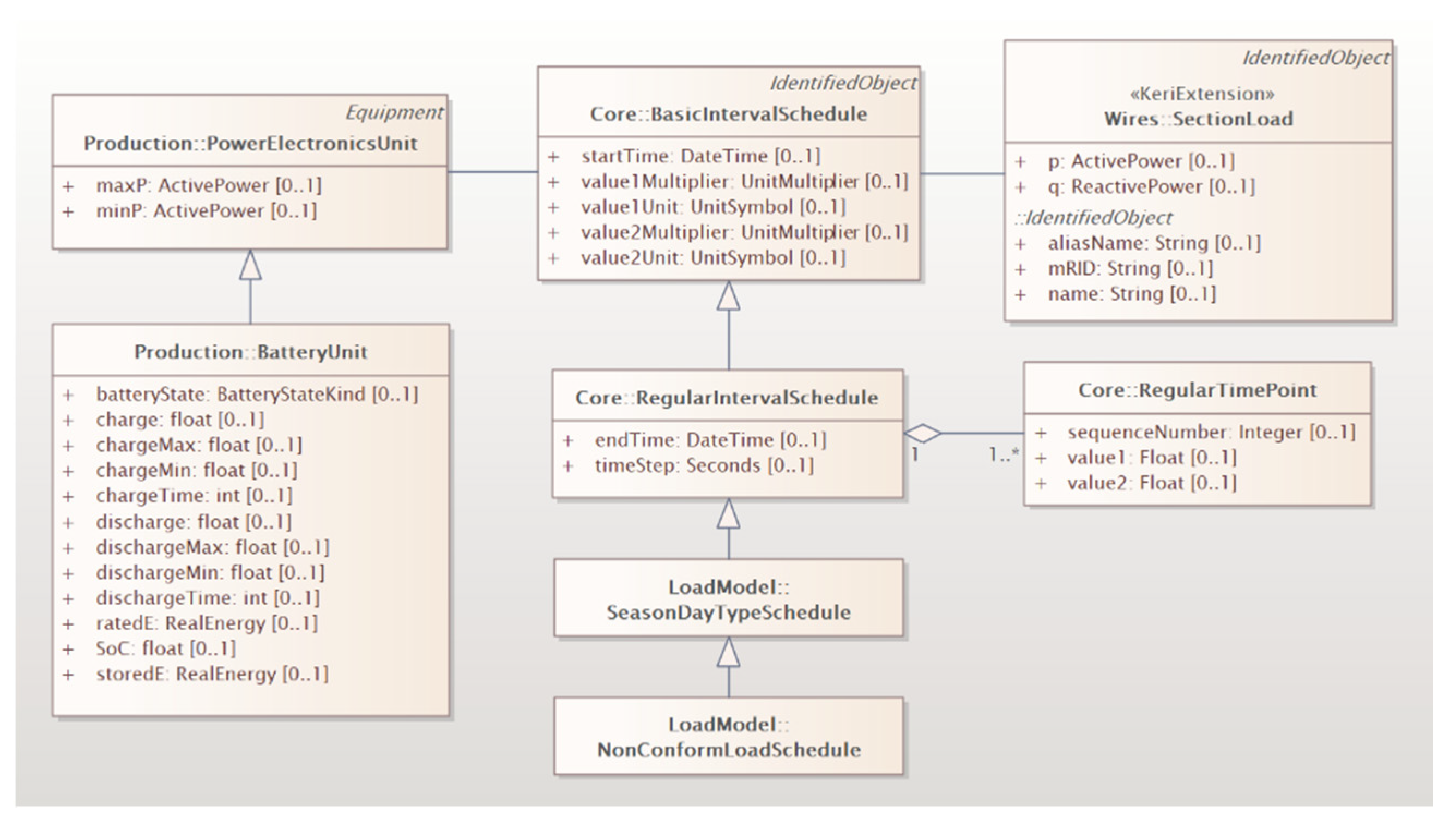
Figure 14 shows the profile expressed in the UML diagram for the prediction of generation and load, which is extended by considering the requirements of the carbon-free islands. The profile—a subset of the entire CIM—is derived by using the CIM EA tool, as shown in
Figure 14 and
Figure 15a. The profile for the prediction of generation and load consists of ‘PowerElectronicsUnit’, ‘BatteryUnit’, ‘BasicIntervalSchedule’, ‘RegularIntervalSchedule’, ‘SeasonDayTypeSchedule’, ‘NonConformLoadSchedule’, ‘RegularTimePoint’, and ‘SectionLoad’ classes. The ‘SectionLoad’ is a CIM extension class and, except for that, the rest are original CIM classes. The ‘BasicIntervalSchedule’ class has an association relationship with ‘PowerElectronicsUnit’ and ‘SectionLoad’.
Figure 14 and
Figure 15a represent the profile containing the metadata for the CIM, which explains its packages, classes, attributes, and associations.
Figure 15b shows data exchanged between the components for the prediction of generation and load. The payload for the output from the energy forecasting application is created by referring to the CIM-based profile. The payload shown in
Figure 15b, created by referring to the profile shown in
Figure 15a, is transferred to the ZeroMQ-based middleware so that data can be exchanged with other components. The interoperability between the internal components of the MG-EMS is ensured by the middleware acting as a data transfer broker between the components.
5.2. Scenario 2: Service Restoration
Figure 16 shows the profile expressed in the UML diagram for the service restoration plan using the ESS, which is extended by considering the requirements of the carbon-free islands. The profile is derived by using the CIM EA tool, as shown in
Figure 16 and
Figure 17a.
Figure 17a,b show the profile and payload used for data exchange to operate the service restoration application, respectively. The profile for the service restoration plan using the ESS consists of ‘Restoration’, ‘RestorationFuzzy’, ‘SectionGroup’, ‘Section’, ‘SectionLoad’, ‘Fuzzy’, ‘MembershipFunction’, ‘Fault’, ‘RestorationType’, ‘ACLineSegment’, and ‘BatteryUnit’ classes. The ‘ACLineSegment’ and ‘BatteryUnit’ are original CIM classes, while the ‘Restoration’, ‘RestorationFuzzy’, ‘SectionGroup’, ‘Section’, ‘SectionLoad’, ‘Fuzzy’, ‘MembershipFunction’, ‘Fault’, and ‘RestorationType’ are CIM extension classes. The ‘Restoration’ class has an association relationship with ‘Fault’, ‘RestorationFuzzy’, and ‘SectionGroup’. The ‘SectionGroup’—meaning a unit section surrounded by automatic switches—is composed of multiple ‘Section’ and ‘SectionLoad’ classes.
Figure 18 shows the payload including information on the outage area, load pattern, ESS charging/discharging pattern, network topology, and service restoration plans. The load and ESS charging/discharging pattern in the form of payload, as shown in
Figure 15b, are outputs of the energy forecasting application. The outage area, load pattern, ESS charging/discharging pattern, and network topology are received as inputs to the service restoration application. In addition, the service restoration application outputs the resulting service restoration plan in the form of payload, as shown in
Figure 17b. All payloads that are inputs/outputs of the application are created by referring to the profile for each interface.
Table 3 indicates the data size and data exchange speed for all standard interfaces required to operate the service restoration application. As shown in the table, the data size and data exchange speed are relatively reasonable given that EMSs operate in minutes.
The interoperable platform proposed in this paper can be applied not only to the energy forecasting and service restoration applications, but also to other applications, by utilizing the standard interface. For any interconnection between components, the same approach presented in this paper—which includes use case analysis, design of business objects, gap analysis, and CIM extension—can be utilized for securing interoperability. Through the case study, it was confirmed that the MG-EMS operates smoothly even if the CIM-based interoperability method is applied. Since the MG-EMS proposed in this paper developed the standard interface, it is expected that applications implemented based on the standard interface will be able to be accommodated in the future.


