1. Introduction
The Information Driven Incident Response (INDIRES) project has been realized in the RFCS UE program between 2017 and 2020 [
1]. One of the goals of the project was the modelling and designing of a new type of a drilling device wherein novel solutions and ideas were used. However, in many typical solutions for systems of cutting, drilling, and milling the process is achieved by generating appropriate forces or torques to act on a substrate, causing its destruction and obtaining a hole. For the improved efficiency of the drilling process, impact heads are also used. In the traditional drilling process, the natural frequencies do not usually occur and, in special situations, this process is often quite long and sometimes dangerous. However, if we can determine the type of rock or substrate materials and thus determine the natural frequency of these materials, we can generate the frequency equal or close to the natural frequency and, in consequence, we can drill holes in a shorter time than with the traditional method. In that way, the idea of a novel method of drilling by using a torsional torque generator in a drilling process was born. During the preparation of the project assumptions, it was proposed that we take advantage of an innovative drilling device using the material’s natural frequency to accelerate the drilling process. The concept of using electromagnetically excited torsional vibrations in the drilling process was originally analyzed by means of numerical methods. As part of the experimental work, sandstone walls were drilled. The first experiment was conducted in cooperation with the KOMAG mining institute. The first laboratory stand included an induction motor and an induction torque generator. The torsional torque generator is a specific kind of a squirrel cage induction machine in which higher magneto motive force space harmonics produce torsional electromagnetic torques [
2]. These torques have frequencies depending on the frequency of the power supply and also on the current rotating speed of the rotor shaft. For the proposed working set a typical drill bit was used. As mentioned earlier, the first tests were carried out on sandstone rock since that rock belongs to a group of rocks that harden over time, assuming a compact structure resistant to mechanical damage, as well as pressure and abrasion.
The obtained results showing the acceleration process of drilling (presented in Figure 1 in
Section 2) in laboratory tests initially confirmed the correctness of the concept of using torsional vibrations in the drilling process. In consequence, after the research had been finished, the idea of an innovative device was created [
3,
4,
5]. The novel device can be a new tool used not only by mines rescue and incident management teams but also in other situations. The note is also made of scenarios not related to mining but with similar characteristics of a particular relevance (e.g., rescuing people in collapsed buildings following natural disasters, most notably earthquakes, gas explosions, etc.). In those situations, a highly efficient drilling rig used by a rescue team can be applied to rescue people from a hazard area. Such equipment could be used to drill a tunnel through solid rock or rubble (e.g., to reach trapped miners) with the advantage of having a small size and weight, and the ability to operate on internal batteries, which is not the case with typical drilling rig solutions. In this solution, the pulsating torque is produced using an electromagnetic torsional generator and the main torque is produced by the main motor.
The problem of the control system of such a device is very complex due to its construction. In this article, the authors present the idea of an innovative drilling rig, its mathematical model and analysis results for the proposed control method, variants of powering the drilling rig from the grid, and an inverter with vector control.
2. What the Electromagnetic Drilling Rig Stands for
The described electromagnetic drilling rig is a device that uses torsional vibrations in the rock drilling process, which are produced by an electromagnetic generator of torsional vibrations. The electromagnetic drilling rig consists of several main elements: the main drive motor (MDM) [
2,
6], the induction torque converter (ITC) [
3,
4,
5,
6,
7], the torsional vibration generator (TG) [
5,
7], and elements such as a cutting head (DH) and an internal screw conveyor. Figure 2 shows, in a simplified way, the kinematic chain of the electromagnetic drilling rig. The electromagnetic drilling rig is a specific device with characteristic features related with the double supply system. The source power can be delivered to the main drive motor (MDM), which is indicated in
Figure 1 by power
PMDM, and also to the electromagnetic torsional generator (TG), which is indicated in
Figure 2 by power
PTG. The power of the source (i.e., the power
PMDM of the MDM and power
PTG of the TG), is converted into the total driving torque of the cutting head (DH), which consists of the torque
TMDM generated by the MDM and the torque
TTG generated by the TG. The torque produced by an inductive torsional vibration generator (TG) consists of an asynchronous torque (in other words constant or slowly alternating) and alternating torque with different frequencies and different amplitudes. As it is shown in
Figure 1, the torque generated by TG acts in two directions, towards the drilling head (DH) and towards the main drive motor (MDM). Propagation of the alternating torque towards MDM is undesired and some dumping methods locking this propagation direction should be proposed. One of the solutions to this issue is implementation of the induction torque converter (ITC) between TG and MDM in the kinematic chain. The ITC blocks the propagation of the alternating torque towards the MDM. To check the general idea of drilling supported by electromagnetically induced torsional vibration a simple stand was created in the KOMAG Institute of Mining Technology (Gliwice, Poland) laboratory facility.
The laboratory stand for checking the effectiveness of the new method of drilling consisted of the Sg 132s4 induction squirrel cage motor (5 kW, 400 V, 50 Hz, pole pairs
p = 2), directly stiff connected by a shaft with the generator (constructed on the stator taken from the Sg 132s4 motor) [
7] and auxiliary equipment. In
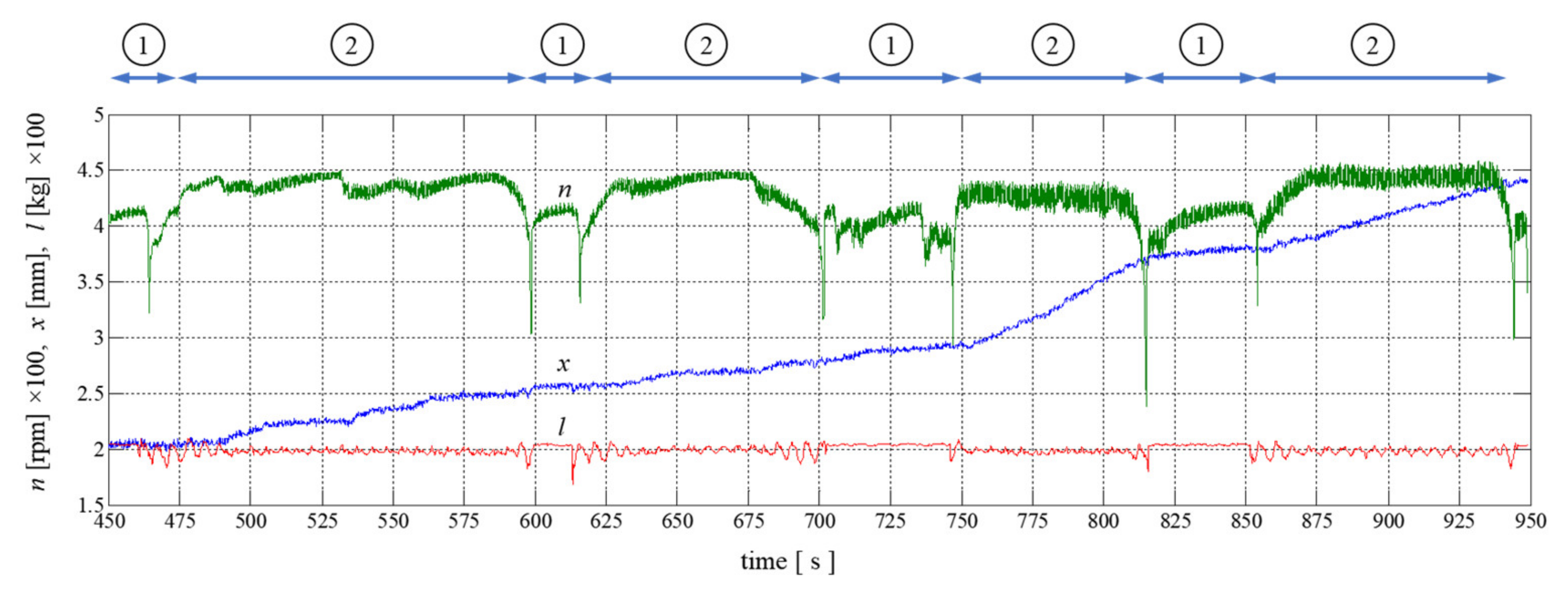
Figure 1 there are presented the results of drilling periodically supported by torsional vibration in a sandstone wall.
The torsional vibration generator with the main drive motor was turned on and off alternately. The periods in which only the main drive motor was powered are marked in
Figure 1. by 1, and the periods in which the generator was also turned on are denoted by 2 in
Figure 1. In the periods in which the vibration generator is turned on, you can clearly see the acceleration of the drilling process and greater penetration of the rock. Additionally, there is an increase and decrease in the load measured by the force sensor, which proves the progress in drilling (i.e., rock drill ability) [
8]. Having such promising results, it was decided to submit a grant application to the European Research Fund for Coal and Steel. As part of the acquired INDIRES (Information Driven Incident Response) project [
1], all drilling rig components were designed.
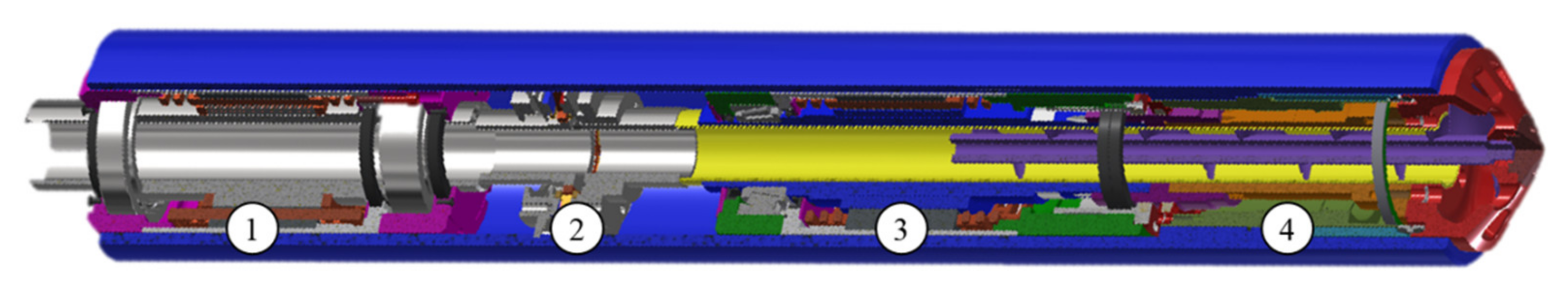
Figure 3 shows a longitudinal section through the designed drilling rig. All components have hollow shafts, and the potential stone output could be transported via an internal screw conveyor.
A specific feature (i.e., powering two elements of the drilling rig) which has already been emphasized earlier gives wide possibilities of steering and controlling the drilling process. In the further part of the article, the necessary mathematical models of the drilling rig components will be presented, which are needed to study the simulation of various power supply variants of the main drive motor and the electromagnetic torsional vibration generator.
3. Mathematical Model of Drilling Rig with Supply and Control System
The issues of modeling the components of the drilling rig were discussed in articles on the main drive motor [
3,
7], torsional vibration generator [
2,
5,
6], and induction torque converter [
4,
6]. The publication presents the issues of modeling with the use of field techniques, but also formulates mathematical models in the form of systems of ordinary differential equations, which are convenient for simulation studies (e.g., involving various power supply methods). For example, the main drive motor made in the form of a squirrel-cage induction motor can be powered not only directly from the mains but also in a frequency converter or from an inverter with vector control with respect to the rotor flux. The mathematical model of the drilling rig is presented for the purpose of formal order and ease of use for the reader. The derivation of the mathematical model of the drilling rig and its elements can be found in [
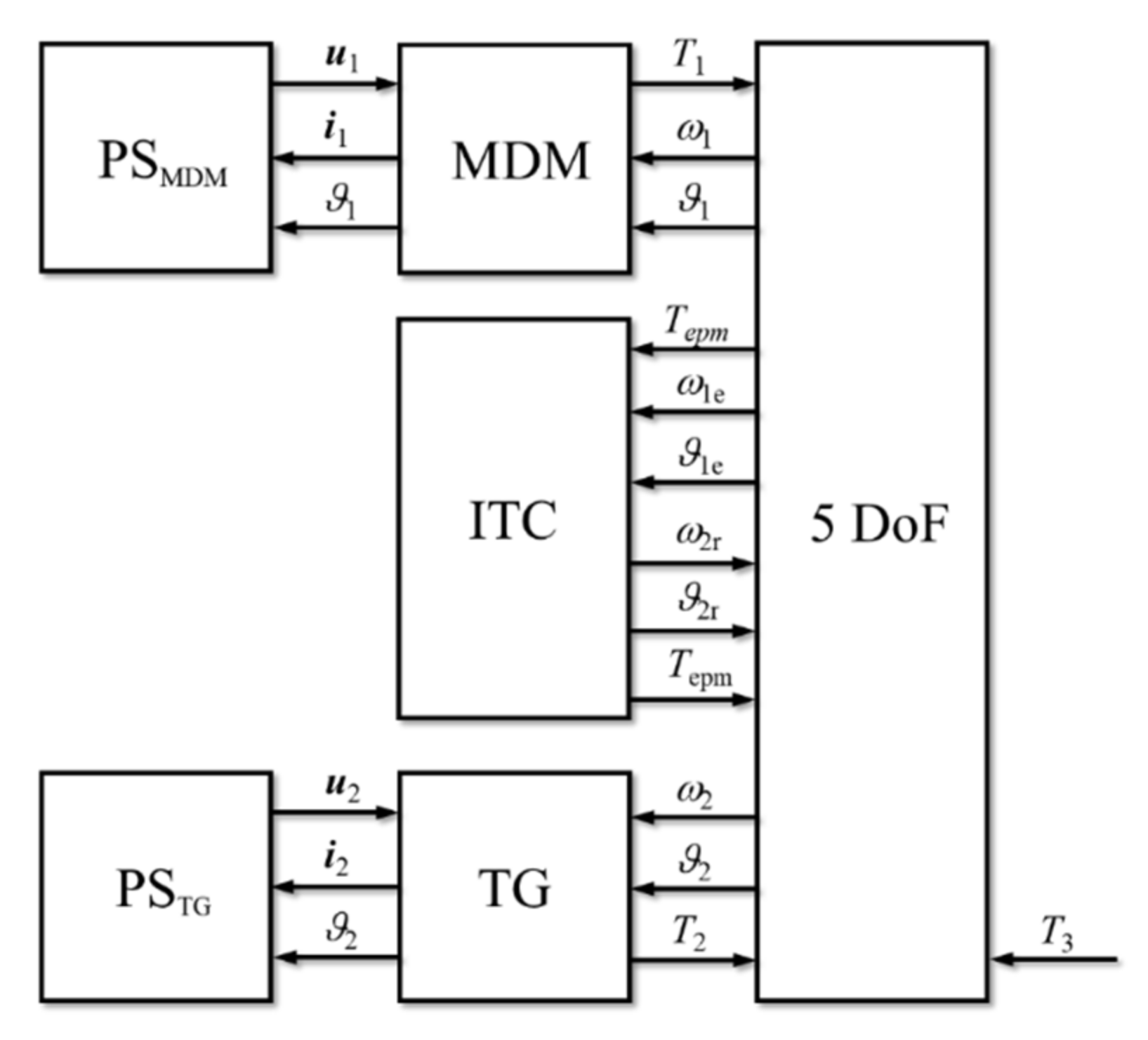
6]. In general, the mathematical model of the drilling rig in the form of ordinary differential equations can be presented in a block form and its kinematic chain consists of five degrees of freedom, as it is shown in
Figure 4. Each block presents a set of differential equations specific for a given component of the drilling rig. The individual blocks will be related to each other or dependent on the magnitude of variables, such as angular displacements, angular velocities, torque etc. The MDM motor drives the first inertial mass of the kinematic chain of the drilling rig with torque
T1 and it responds with angular displacement
ϑ1 and angular speed
ω1, respectively. The shaft speed increases and the angular speed
ωe1 of the excitation circuit (secondary inertial mass of kinematic chain) of ITC [
4,
6] increases as well, which results in generating the electromagnetic torque
Tepm. That torque drives the third inertial mass, the receiving element of ITC, which rotates with the angular speed
ωr2. It is worth underlining that the excitation circuit and receiving circuit are coupled only in the electromagnetic way, there is no mechanical coupling [
4,
6]. The shaft between ITC and TG is rotating with the angular speed
ω2 and it influences the TG behavior. The torsional generator TG adds the torque
T2 on the drilling head which is loaded by the torque
T3. The blocks denoted by PS
MDM and PS
TG in
Figure 4 represent the power supply of the main driving motor MDM and torque converter TG; it can be a simple grid power source [
1,
2,
8,
9] or more sophisticated such as the PWM (pulse width modulated) inverter with the vector control algorithm [
10,
11,
12,
13,
14,
15,
16].
The mathematical model of the squirrel cage motor, playing in our drilling rig the role of the main driving motor MDM, in terms of the ordinary differential equation is as follows [
3,
7]:
where
u1αβ is the 2 × 1 dimensional vector of stator voltage,
i1αβ, irdq, respectively, are the 2 × 1 dimensional vector of stator and rotor currents,
αβ is the stator coordinate system,
dq is the rotor coordinate systems,
Rsαβ,
Rrdq are the diagonal 2 × 2 dimensional matrices of stator and rotor resistances,
Lσsαβ,
Lσrdq are the diagonal 2 × 2 dimensional matrices of stator and rotor leakage inductances,
Mssαβ,
Mrrdq are the 2 × 2 dimensional diagonal matrices of stator and rotor self-inductances,
Msrαβdq(
ϑ1) is the full 2 × 2 dimensional matrix of stator and rotor mutual-inductances,
ϑ1 is the variable rotor angular displacement angle,
ω1 is the angular speed, and
p is the pole pairs.
The mathematical model of the induction torque converter ITC, expressed in terms of the ordinary differential equation in the canonical and matrix forms, is as follows [
4,
7]:
where
itk is the current of
k-th phase,
Rk is the resistance of
k-th phase,
keil,
keir are the induced voltage factor of left and right sides of
i-coil/phase,
Lii is the self-inductance of a given
i-phase,
Lij is the mutual inductances between the
i-th and
j-th phase,
ωe1 is the angular speed of excitation circuit of ITC,
ωr2 is the angular speed of receiving circuit of ITC.
The mathematical model of the torque vibration generator TG, expressed in terms of the ordinary differential equation in the canonical and matrix forms [
5,
7], has the following form:
where
αβ and
dq denote the coordinate system of the variables (referred to the stator and rotor respectively),
Rr2dq,
Rr6dq,
Rr10dq,
Lσr2dq,
Lσr6dq,
Lσr10dq are the 2 × 2 dimensional, diagonal matrices of rotor resistances and inductances,
Mrr2dq,
Mrr6dq,
Mrr10dq are the 2 × 2 dimensional matrices of rotor self-inductances,
Msr2αβdq(
ϑ2),
Msr6αβdq(
ϑ2),
Msr10αβdq(
ϑ2) are the 2 × 2 dimensional, full matrices of stator-rotor mutual inductances,
ir2dq,
ir6dq,
ir10dq are the 2 × 1 dimensional vectors of rotor currents,
u2αβ,
i2αβ are the 2 × 1 dimensional vectors of stator voltages and currents,
ω2 is the angular rotor speed,
ϑ2 is the angular rotor displacement, and
p is the pole pair.
Torques generated by all the components of the drilling rig can be calculated for MDM, ITC and TG according to the following formulas:
where
ϑ is the angular position of winding coils of receiving circuit,
r1 is the internal radius of permanent magnets of excitation circuit,
l is the length of one side of coil in the field of a permanent magnet,
N is the number of turns in coil of single phase, and
Bi(
ϑ) is the average magnetic flux density for
i-phase [
2].
The kinematic chain of the mechanical system of a drilling rig consists of five DoF and it can be expressed in the form of the second order differential equation, derived using Euler Lagrange’s formalism [
4,
5,
7], as follows:
where
J1,
J1e,
J2r,
J2,
J3 are, respectively, the MDM rotor, excitation circuit of ITC, receiving circuit of ITC, TG rotor and drilling head mass moments of inertia;
k1,
b1 are the shaft stiffness and dumping between MDM and ITC;
k2,
b2 are the shaft stiffness and damping between ITC and TG; and
k3,
b3 are the shaft stiffness and dumping between TG and drilling head.
It is worth underlining that the first 2 DoF of the drilling rig kinematic chain is coupled only by the electromagnetic field (the electromagnetic torque with the next 3 DoF part of this kinematic chain). There is no mechanical coupling between these two parts, and it guarantees strong dumping transmission of torsional vibration from TG towards MDM. Assuming that mass moments of inertia J1, J1e, J2, J3 equal 0.02 kg⋅m2 and J2r = 0.01 kg⋅m2 and stiffnesses of shafts k1, k2, k3 equal 50 kN⋅m/rad, the natural frequencies of 5 DoF kinematic chain are as follows: f01 = 355.9 Hz, f02 = 0 Hz, f03 = 174 Hz, f04 = 448.1 Hz, f05 = 288.1 Hz.
4. Drilling Rig Mathematical Model Implementation and Simulations Results
The drilling rig can be supplied from two independent sources of energy, separately for the main driving motor MDM and the torsional vibration generator TG if it is desired/required. This dual system of supply gives high flexibility in order to shape the desired speed, torque, and torque frequency component applied to the drilling head. The simple way to feed the MDM and TG is to use supply from a three-phase network or three-phase frequency converters. A more sophisticated method of supply and control utilizes three-phase converters with vector control algorithms with respect to the rotor flux—the so-called RFOC (Rotor Field Oriented Control) system. The simulation tests were provided using MATLAB/Simulink environments, and they were divided into three stages according to different kinds of power supply, such as:
Stage 1. Three-phase network supply; the MDM was energized (3 × 400 V, 50 Hz, wye-connected stator windings) and the drilling head was loaded by 10 Nm in the first test and was locked in the second test. The test covered the free start of the whole drilling rig and free acceleration, after 3 s the load was applied in the first test and the drilling head was locked in the second test.
Stage 2. Three-phase network supply; the MDM was energized from the beginning and the TG was energized 1 s after the MDM start. The test covered the free start of the whole drilling rig and free acceleration, after 3 s the load was applied.
Stage 3. The MDM motor was supplied with RFOC frequency inverter, the drilling head was loaded by 10 Nm, the TG generator was on and also supplied with RFOC frequency inverter. Different output frequencies were set for RFOC frequency inverters.
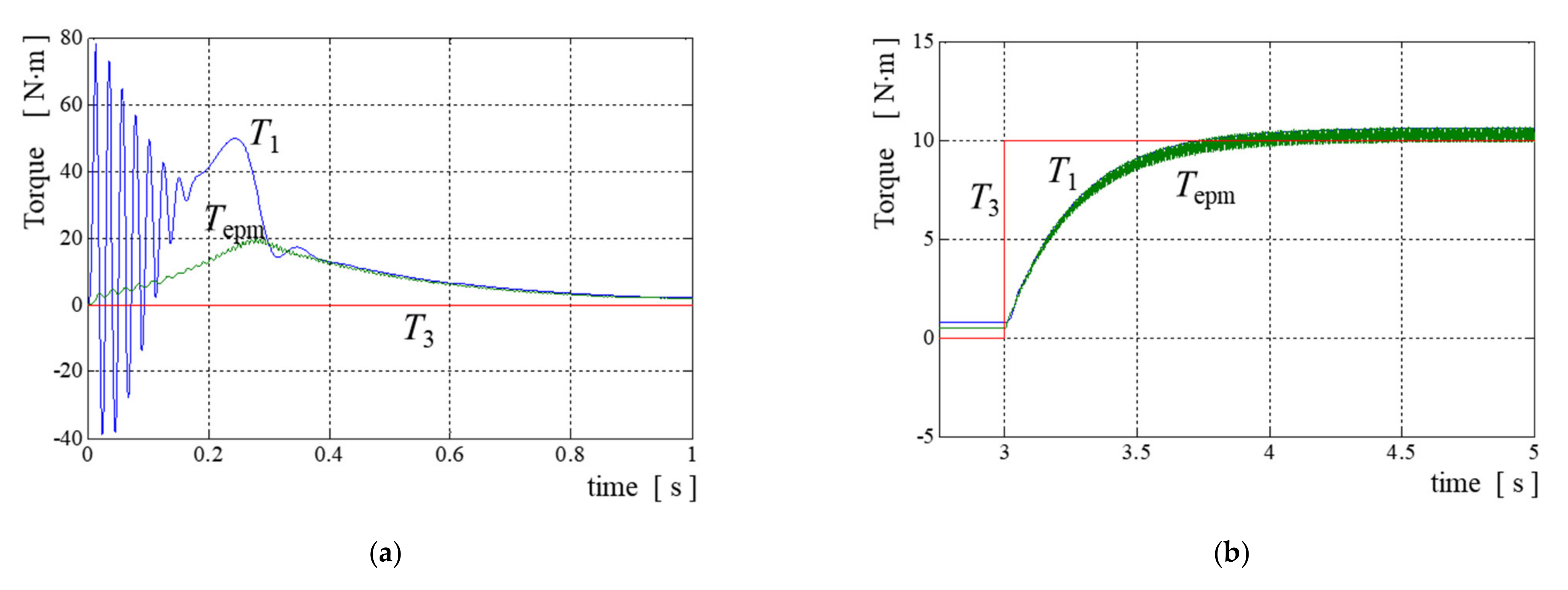
The obtained results of the simulation within Stage 1 are presented in
Figure 5 and
Figure 6. In
Figure 5a there is presented the electromagnetic torque increase
T1 of MDM, torque
Tepm transferred (produced) in ITC and the resultant torque
T3 exerted to the rotor of TG (torque generator is not supplied). The time plot of
T1 is typical for the induction motor accelerating inertial masses up to
t = 0.28 s.
As torque
T1 increases, torque
Tepm transferred by ITC also increases, it reaches the maximum value when the rotor angular speed
ω1 of MDM is close to the maximum speed (between the rated and synchronous speeds; please refer to
Figure 6a).
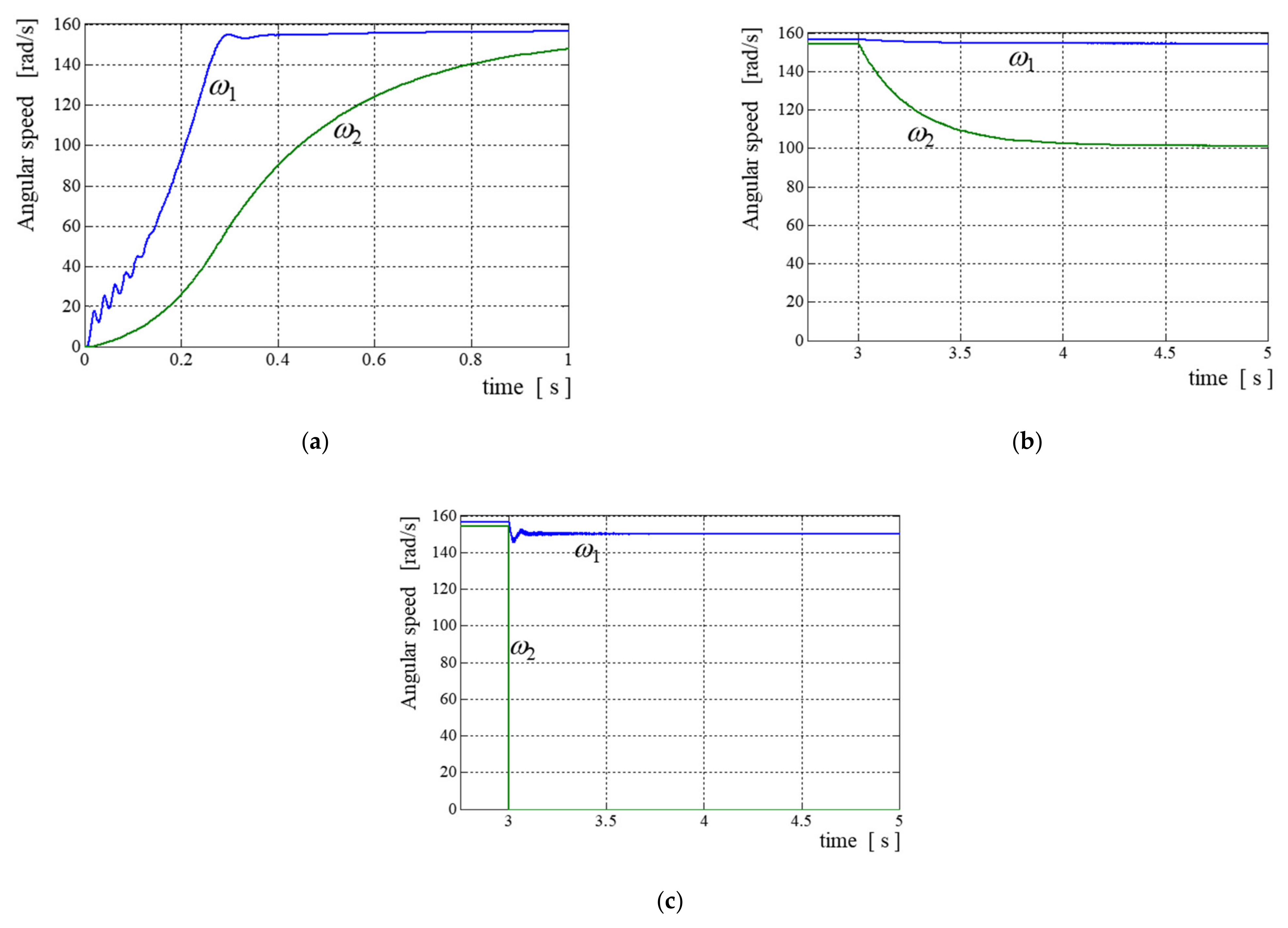
In
Figure 6a we can see that the rotor angular speed
ω2 of TG gradually increases and tends to equalize with the
ω1 angular speed. After 3 s the load (equal to 10 Nm) was applied to the drilling head. In
Figure 5b we can see as torques
T1 and
Tepm increase and tend to balance load torque
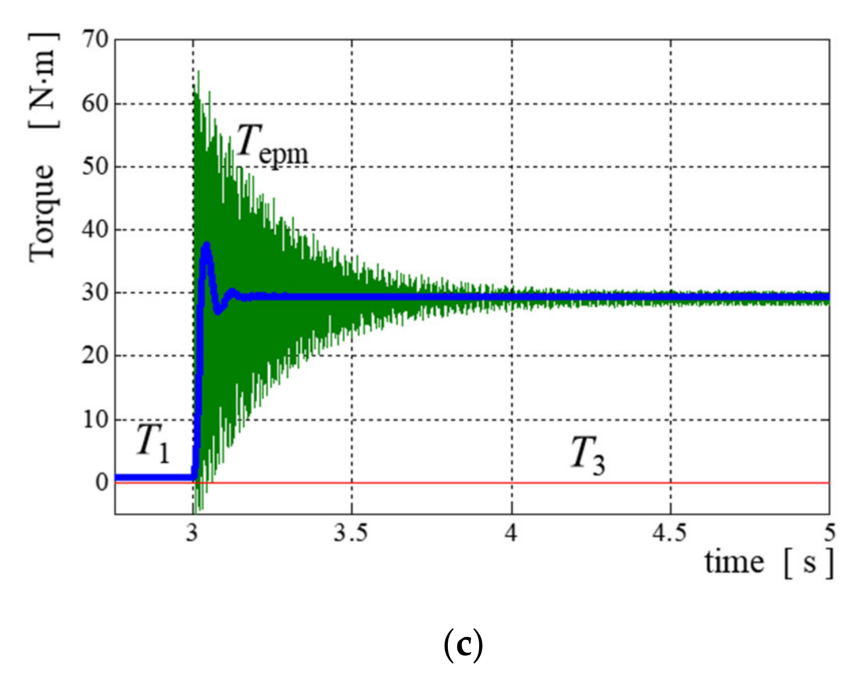
T3. The second test assumed the same free start of the whole drilling rig but in the time equal to 3 s the drilling head was locked, and it stopped. This resulted in a rapid rising of torque
Tepm, but the torque also covered the dumped periodic component. Finally, it resulted in step torque
T1 response of MDM (see
Figure 5c) and speed
ω1 decreased slightly (see
Figure 6c).
Summarizing the behavior of the drilling rig under the test provided within Stage 1, it can be concluded that its behavior is as expected and is logical from the physical point of view. When the drilling head is loaded, the ITC slows down visibly, and MDM slows slightly down (whereas the torque of MDM increases). The conclusion is that the electromagnetic torque is transferred correctly in both directions according to physical laws.
The obtained results of the simulation within Stage 2 are presented in
Figure 7 and
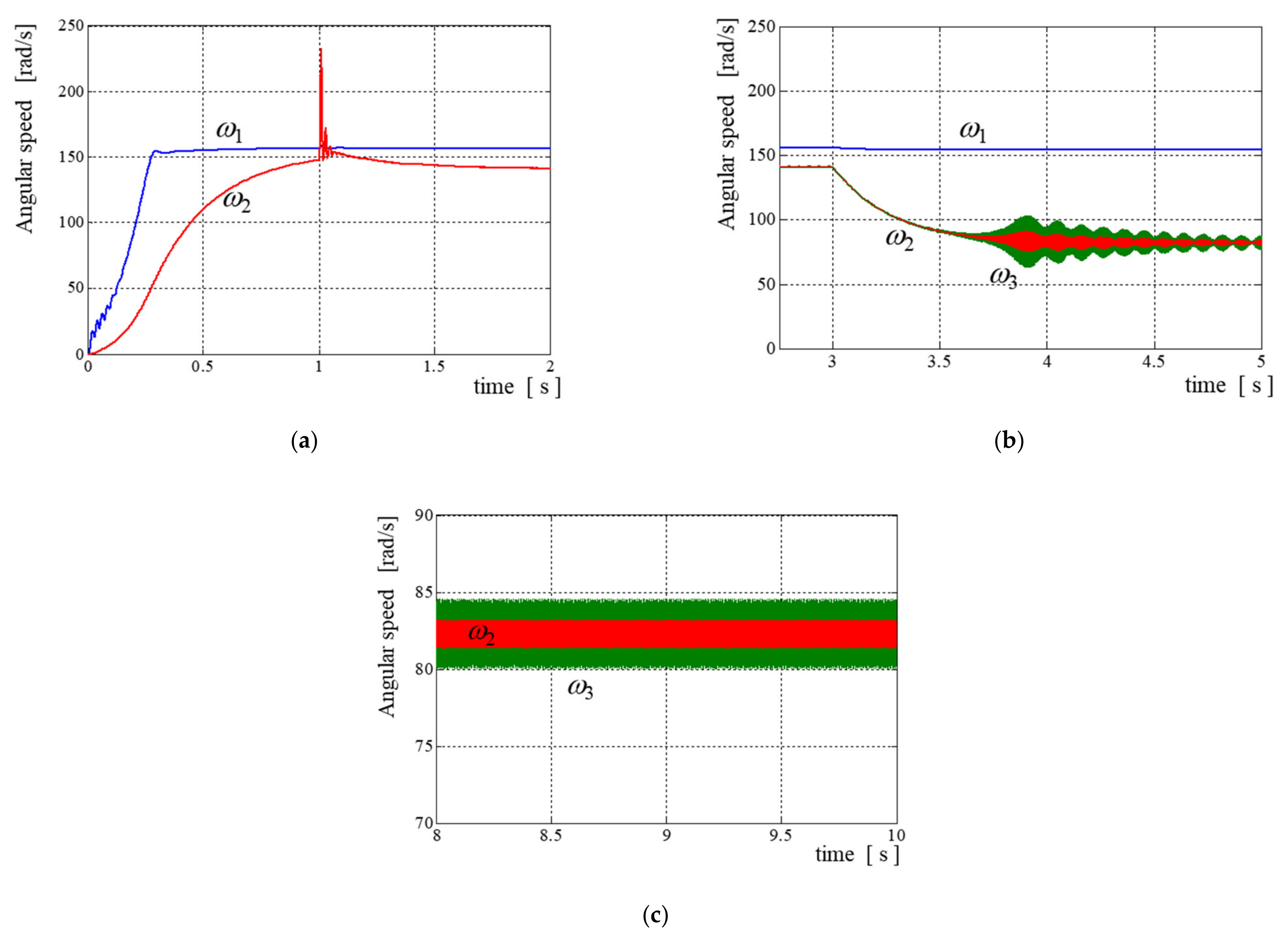
Figure 8. In
Figure 7a there is presented the angular speed
ω1 increase of MDM and the angular speed
ω2 increase of TG rotor up to
t = 1 s when the TG starts to be supplied. The torque vibration generator TG is supplied in such a way that the magnetic field in the air gap rotates in the opposite direction to the main drive motor MDM magnetic fields. It results in an increase of the load to MDM, so it is a small disadvantage, but the positive thing is that the torsional torque generated by TG has more uniform amplitudes [
4]. In
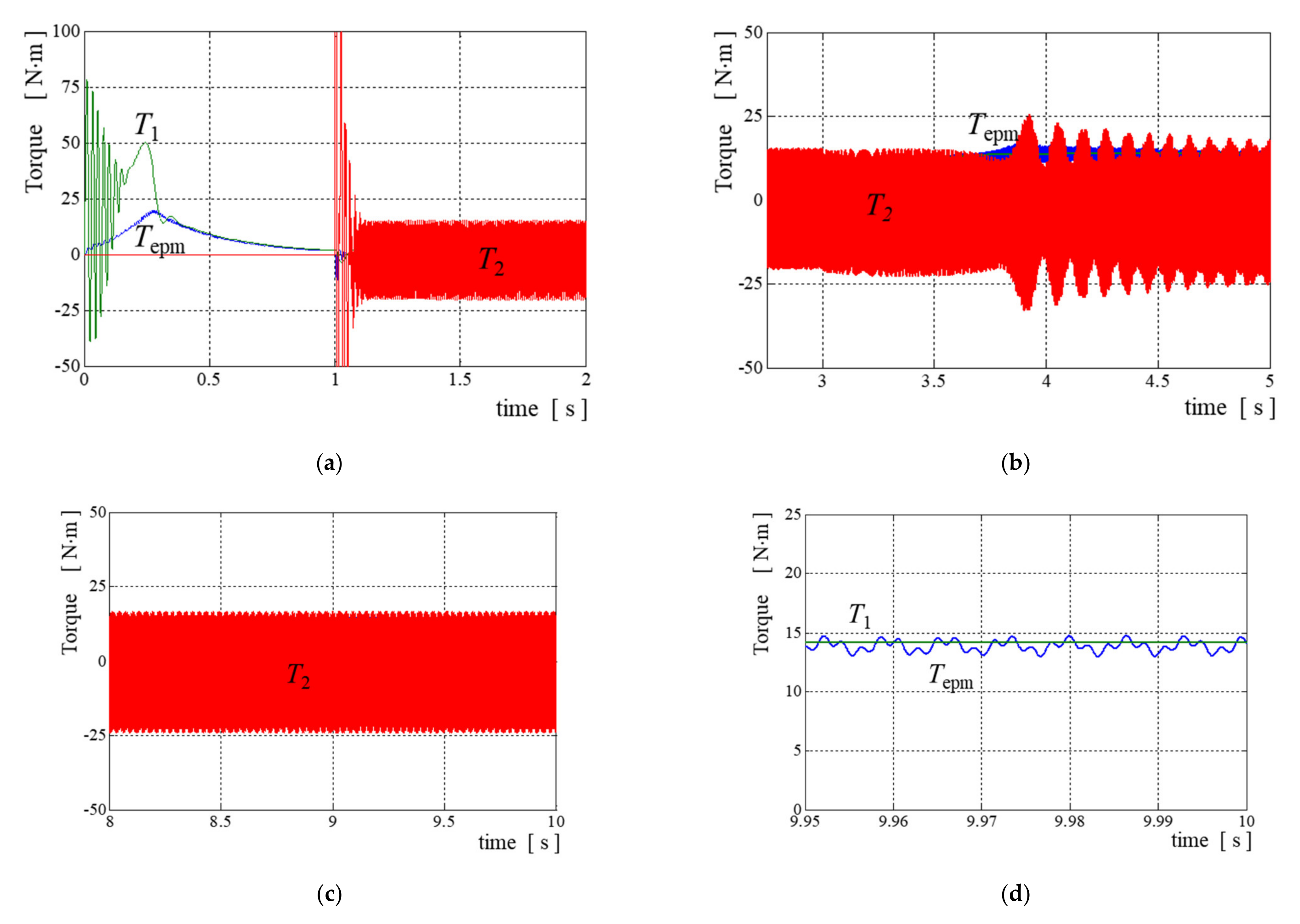
Figure 8a what can be seen is the huge impact of the torque produced by TG after supply and its periodic component finally stabilizes at the amplitude equal to 11 Nm. After another 2 s (see
Figure 7b and
Figure 8b) the load is applied to the drilling head and the rotating speed of the drilling head and TG gradually decreases, and after going through some disturbances swinging finally stabilizes between 80 and 84.5 rad/s in the case of the drilling head motion (
ω3 periodic component frequency is 476 Hz) and between 81.4 and 83.2 rad/s in the case of TG rotor motion (
ω2 periodic component frequency is 476 Hz).
The periodic component of the torque generated by TG has a 15 Nm amplitude and the frequency near 1 kHz after the generator was supplied, which is depicted in
Figure 8a. When the load was applied to the drilling head, the torque generated by TG started to swing (
Figure 8b) and 3 s later it stabilized (
Figure 8c) with amplitudes of 20 Nm and the frequency near 476 Hz. One of the undamped natural frequencies of 5DoF drilling rig kinematic chain equals
f04 = 448.1 Hz, and it seems that the torsional generator rotor is near torsional resonance between the drilling head and TG rotor. The last 50 ms of time plots presenting torque
T1 generated by MDM and torque
Tepm generated by ITC are presented in
Figure 8d. As it is easy to observe, the torsional vibrations are not transferred to the main motor MDM.
The obtained results of the simulation within Stage 3 are presented in
Figure 9. Within this test, both the MDM and the TG were supplied from the RFOC frequency inverter. Three different reference angular rotating speeds, but the same for MDM and TG (which means three different output frequencies of inverters) were set equal
ωset ∈ {25, 75, 125} rad/s. The reference speed in every single test increased gradually from zero to the set value within 1 s. After another 0.5 s, the drilling head was loaded by the torque equal to 10 Nm. In
Figure 9a we can see the plots of MDM and TG angular speeds (red line—TG speed) at different angular speed of drilling head. The angular speed of MDM is increasing smoothly with small over regulation at the desired speed, but TG starts unregularly at the beginning. This non-uniform start is connected with torsional resonances raised in the drilling rig kinematic chain, which is clearly seen in
Figure 9b,c as a high amplitude increase of
T2 torque between time 0.6 s up to 1 s. The time plots representing the torque generated by TG under load are presented in
Figure 9b,c, and the resultant variable components of the torque amplitudes equal 20 Nm, but it consists of different torsional torque frequencies and amplitudes. The harmonics of torque
T2 in all cases of the referred angular speed are summarized in
Table 1.
The data collected in
Table 1 can be approximated by the line plot representing the frequency of torque harmonics versus the angular rotating speed (for example, for the lowest order harmonics the line plot fulfills equation
f01 = 3.8
ω − 32.67 Hz and for the highest ones it fulfills equation
f05 = 22.93
ω + 33.25 Hz).


