1. Introduction
The Jeffcott rotor is represented by a simply supported flexible massless shaft having a rigid disc at the mid-span. The offset between the center of gravity and the center of rotation is known as eccentricity. Several components of the Jeffcott rotor are characterized by nonlinear behavior, and this system is in general nonlinear. The nonlinear properties of the Jeffcott rotor can lead to different behavior of the rotor from that predicted by a linear model; thus, an investigation of the effects of nonlinearities is required.
The nonlinear vibration of rotor systems has been studied by several researchers since the pioneering studies of Yamamoto [
1] and Ehrich [
2], where nonlinearity appeared for the first time due to the clearance in bearings at supporting points. Black [
3] highlighted the condition of the existence of the synchronous full annular rub solution, and Muszynska [
4] explored some possible responses of the rotor–stator system. Childs [
5] considered fractional subharmonic resonance in a horizontally supported rotor, and Bently et al. [
6] reported the synchronous response, which exhibits typical jump phenomena. Jiang and Ulbrich [
7] analyzed the stability of the full annular rub solutions of a simple nonlinear Jeffcott rotor with the symmetrical clearance effect. The nonlinear normal modes of a horizontally supported Jeffcott rotor were investigated by Yabuno et al. [
8]. The frequency response curves were characterized in the primary resonance for various values of the eccentricity. The full annular rub motions of a nonlinear Jeffcott rotor were investigated by Biao and Shu in [
9], providing a basis for the parametric design of the rotor system with the help of the averaging method. Jeng et al. [
10] applied the response integration method to determine periodic motion in the response of the rub-impact rotor system, constructing a bifurcation diagram using Poincare section points.
The nonlinear vibration phenomenon induced by aircraft hovering flight in a rub-impact rotor system that involves two general supports with cubic stiffness was examined by Hou et al. [
11]. The influence of aircraft hovering flight on the rotor system has been thought of as a maneuver load to obtain the equations of motion.
Yang et al. [
12] extended the concept of likelihood, proposing a likelihood-based approach for mixed uncertainties representation and quantification, developing a single-loop sampling algorithm to reduce the computational cost.
Liang et al. [
13] studied the offset disc rotor system with a mechanical gear coupling, taking into account the nonlinear restoring force of rotor support and the coupling misalignment and employing the harmonic balance method to obtain periodic solutions. Stochastic bifurcation and chaos of a randomly excited rub-impact rotor system with random stiffness was explored in [
14] by Yang et al. using the Chebyshev polynomial approximation method, which is used to reduce a system with a random parameter to an equivalent deterministic one. Fu et al. [
15] studied the effects of bounded uncertain parameters on the nonlinear response of a rub-impact rotor system with an overhung disk using the nonintrusive interval uncertainty propagation method.
The modal characteristic of the modified Jeffcott rotor system having an additional constraint was investigated by Hong et al. [
16]. They showed that the rubbing rotor system possesses a backward whirl mode motion and a forward whirl mode motion, showing that the first can be unstable, and this instability is only the primary mechanism for the partial rub transmitting into dry whip. The dynamic behaviors of an asymmetric horizontally suspended rotor system involving rub-impact force were examined by Saeed et al. [
17]. The whirling motion of the rotor system was controlled by means of four electromagnetic poles. The derived mathematical model was analyzed using perturbation analysis, then the system that includes rub and impact forces was analyzed by means of bifurcation diagrams, frequency spectrum and Poincare maps.
The stability analysis and change in phase difference of the shaft and dry friction damper system having viscous internal damping and gyroscopic moment under coupling of unbalanced force and nonlinear rub-impact excitation was considered by Huang et al. [
18]. It was found that the viscous internal damping has a contribution to improving the stability of the synchronous full annular rub solution, the rub-impact delays the change in phase difference and the gyroscopic moment has an influence on the increase in the phase difference. Nan et al. [
19] investigated the nonlinear dynamics of a rotor-bearing system with cubic nonlinearity, internal clearance, nonlinear Hertzian contact force and nonlinear stiffness of support material. By means of rotor trajectory diagrams, a Poincaré map and bifurcation diagrams, the effects of nonlinear stiffness, mass eccentricity and rotating speed on the dynamic behavior of the system were analyzed. Routes to chaos were found, and dynamic behaviors were analyzed, including multiple periods, inverse bifurcation, paroxysmal bifurcation, jumping phenomena and chaos.
The aim of the present research is to analyze the nonlinear vibrations of a rub-impact Jeffcott rotor with clearances, taking into account internal and external damping, gyroscopic moment and skew symmetric stiffness. The nonlinearities are caused by the cubic nonlinearity of the shaft. The stator deformation is approximated by a rigid casing supported by radial springs. The Optimal Auxiliary Functions Method is used to obtain explicit and accurate approximate analytical solutions for the nonlinear differential governing equations. Our procedure ensures fast convergence of the solutions using only the first iteration, taking advantage of the involved auxiliary functions and optimal convergence-control parameters, without the need to identify the presence of small parameters in the governing equations. The steady-state response and the stability of the solutions are analytically presented for the two stages, as well as the location of jumps. The stability of the solutions for the two stages is established. The stability of the synchronous full annular rub motion is derived by a characteristic equation. using the Routh–Hurwitz criterion. Different parameters on the nonlinear vibrations of a rub-impact Jeffcott rotor with clearance are presented.
2. The Governing Equations of Motion
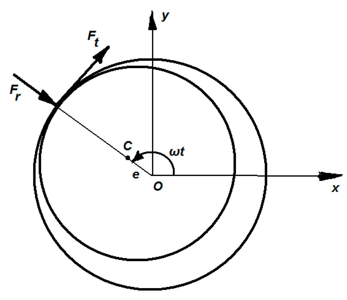
We consider a modified Jeffcott rotor that consists of a massless shaft carrying a disk of mass m at the middle of the span (
Figure 1).
The mass center of the rotor is placed at distance e (eccentricity) from the geometrical center C (
Figure 2).
The deformation of the stator is approximated by a rigid casing supported by radial springs having stiffness Kb, the stiffness of the rotor shaft is Ks and δ denotes the clearance between the rotor and stator. The stator has a rigid ring whose mass is negligible, the Coulomb friction coefficient is μ, the cross-coupling stiffness is Q and the damped coefficients are c1 and c2.
The governing equations of the above-described rubbing rotor system are [
7,
9,
16,
18]:
in which
x and
y are the horizontal and vertical displacement, respectively,
is the radial displacement of the disk,
is the relative speed at the contact point of the rotor,
rdisk is the radius of the disk and
ωw is the whirl angular velocity of the rotor, while
H(
u) is the Heaviside function known as
The symbolic function
sign(
u) is
The nonlinear restoring forces corresponding to
x− and
y− directions are, respectively:
Using the nondimensional variables
and having in view that
vrel > 0 and Equations (2)–(4), the governing dimensionless Equation (1) may be rewritten as
where
,
β = 0 if
R ≤ 1 and
β ≠ 0 if
R > 1.
The nonlinear differential discontinuous Equation (6) is very hard to solve by means of classical procedures. The exact solution for this system is impossible to obtain, so we will try to determine an explicit and accurate analytical approximate solution for the system (6) with the initial conditions
3. An Approximate Solution to the Considered Nonlinear Dynamical System
In the following, we will solve Equations (6) and (7) by applying the Optimal Auxiliary Functions Method (OAFM) [
20,
21,
22,
23,
24,
25].
New time scales are defined for each variable
X,
Y, as:
and Equations (6) and (7) become as shown in Equations (A1) and (A2).
The linear and nonlinear operators corresponding to Equation (A1) will be as shown in Equation (A3).
The approximate solutions of Equation (A1) have two components:
where the initial approximations
X0(τ
1) and
Y0(τ
2) are determined from the linear equations
with the initial conditions (7), which may be rewritten in the forms:
The solution of the systems (10) and (11) will be
By substituting Equation (12) into (A3), it holds (A4) and (A5) from
Appendix A.
The values of the coefficients
Mi and
Pi,
i = 1,2, …, 9 are given in
Appendix B. The functions that appear in Equations (A4) and (A5) are the so-called “source” for the auxiliary functions.
It follows that the first approximations
X1(τ
1) and
Y1(τ
2) can be obtained from the linear differential equations
with the initial conditions obtained from Equations (7) and (12)
After simple manipulations, Equations (13) and (15) can be rewritten as shown in Equations (A6) and (A7).
In order to avoid the presence of the secular terms into Equations (A6) and (A7), we have
Taking into consideration Equations (14), (16), (A6), (A7) and (17), the first approximations become as shown in Equations (A8) and (A9):
The approximate analytical solutions of nonlinear Equations (A1) and (A2) will be obtained from Equations (9), (12), (A8) and (A9).
Numerical Example
In order to prove the accuracy of the proposed technique, a set of values will be considered for the parameters that appear in Equations (A1) and (A2):
The values of the unknown parameters
C1,
C2, …,
C12 could be optimally determined by means of various mathematical procedures, among them being the least square method, collocation method, Ritz method and so on [
26].
For
β = 0, using the collocation method and taking into account Equation (17), we obtain
A = 0.875,
B = 0,
C = −0.0054 and
D = 0:
and the approximate solution
The domain of the solutions (20) and (21) for β = 0 is D1 = [0, 2.83234933].
For
β = 0.001, one can obtain
and the approximate solution for
τD2 = [2.83234933, 3.96296052634]:
In the same way, we can determine the approximate solution on the domains: D3 = [3.96296052634, 5.21481530893], D4 = [5.21481530893, 6.71234340797] and so on.
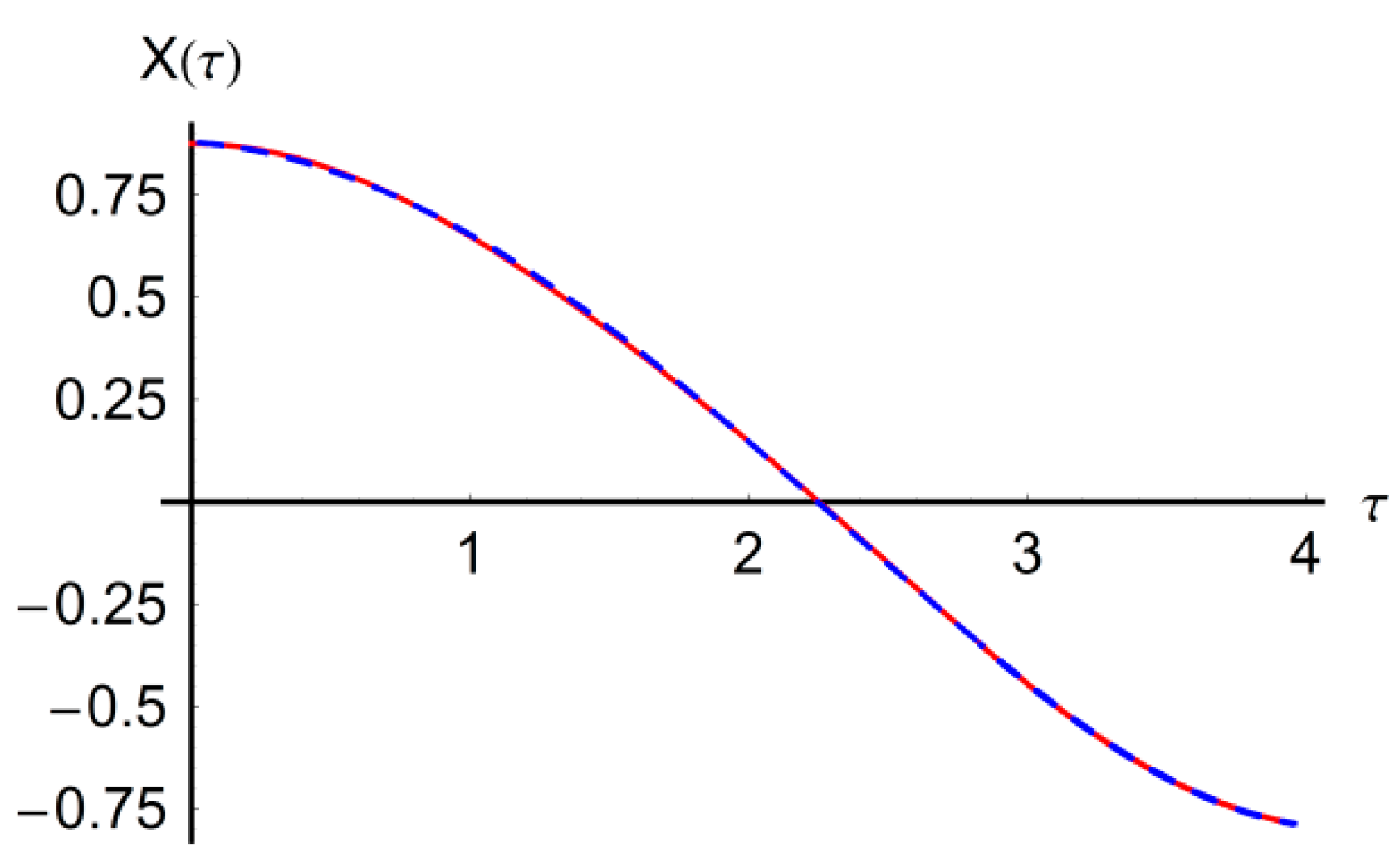
In
Figure 3 and
Figure 4 are presented the graphs of the approximate solutions (20), (23), (21) and (24), respectively, in comparison with the corresponding results obtained by numerical integration. It is clear that the proposed technique is very accurate and efficient at obtaining an approximate solution for the complicated nonlinear differentials of Equations (6) and (7).
4. Steady-State Solution
The steady-state periodic solutions of Equation (6) are
such that one obtains
The steady-state periodic solution is received when
. If the principle of linearized stability is used, the equation must be rewritten as a first-order system. We introduce a new set of variables as:
in which the prime denotes the derivative with respect to
.
Usage of variables
xi,
i = 1,2,3,4 in Equation (28) gives the following nonlinear system
The stationary solution corresponding to the steady-state solution of Equation (28) is obtained by letting
in Equations (28)–(31). The stationary solutions are denoted
,
,
,
. These can be written as:
At lower angular speed Ω, the amplitude of the unbalance response is smaller, and the rotor is in the noncontact situation yielding
β = 0 such that Equations (33) and (34) are simplified as
From Equations (34) and (36), we obtain
where
The steady-state solution exists if
in Equation (37). Let us note that
. It is clear that the condition
is equivalent to the condition
n ≤ 0. Now, Equation (37) can be rewritten as
Using the notations
then Equation (39) becomes
The Equation (41) has one or three real solutions, as follows [
27]. If
D > 0, then Equation (41) has a single solution
leading to the unique solution of Equation (39) in the form
In this first case, the condition of existence of steady-state solutions is
For example, in the particular case when
from Equation (44), one retrieves the conditions of existence of steady-state solution for
β = 0: Ω < 1.1929532871.
If
D < 0, then Equation (39) has three real solutions, respectively
If
D = 0, and if
p =
q = 0, it follows that
, and if
, it follows that
To find regions in the parameter space where the steady-state solution exists, the conditions must be fulfilled.
The jump phenomenon only occurs if all solutions η1, η2, η3, of Equation (39) exist. This means that D ≤ 0, where D is obtained from Equation (42).
5. The Study of Stability
We introduce the derivation from the stationary solution as
Linearizing Equations (28)–(31) around the stationary solution, it follows that
where
and
can be obtained from Equations (33) and (34):
where
For β ≠ 0, from a physical point of view, in Equation (51) should be real and greater than 1 to ensure the correctness of Equation (6). These real solutions of Equation (51) for which correspond to the full annular rub solutions of the rotor–stator system. When rotor angular speed ω (respectively, Ω from Equation (5)) is increased and decreased, it is seen from Equation (51) that the rotor amplitude must jump between the branches with or without rotor rub. The jump phenomena only occur if there exist at least two solutions in Equation (51). The exact solutions of Equation (51) are difficult to be obtained and therefore these solutions can be approximated by numerical procedures.
The stability of the full annular solutions may be determined by the eigenvalues of the Jacobian [
J], which is obtained from Equation (50):
where nonzero terms are
The signs of real parts of eigenvalues of the Jacobian matrix are obtained from the characteristic equation:
where [
I] is the unity matrix, and λ is the eigenvalue of the Jacobian.
Taking into account the expansion (56), the characteristic equation (54) becomes
where
A0–
A3 have the expressions given in Equation (A10).
To remove
, which appears in Equation (A10), from Equations (33), (34) and (53), it follows that
Substituting Equation (58) into Equation (A10), the result is given in Equation (A11).
Taking into account the Routh–Hurwitz criterion, all eigenvalues of the characteristic Equation (57) have negative real parts when the following six inequalities are simultaneously satisfied:
Then, the full annular rub solutions are asymptotically stable. In the expressions (A10), the values of are obtained from Equation (51). If at least one condition (59) is not satisfied, then the full annular rub solutions are unstable. If , then no rub occurs, and therefore, the conditions of stability are (59) but with β = 0 in Expressions (58).
Based on the saddle-node bifurcation (turning point), there is one zero eigenvalue of the Jacobian matrix and condition corresponding to
with
given by Equation (51).
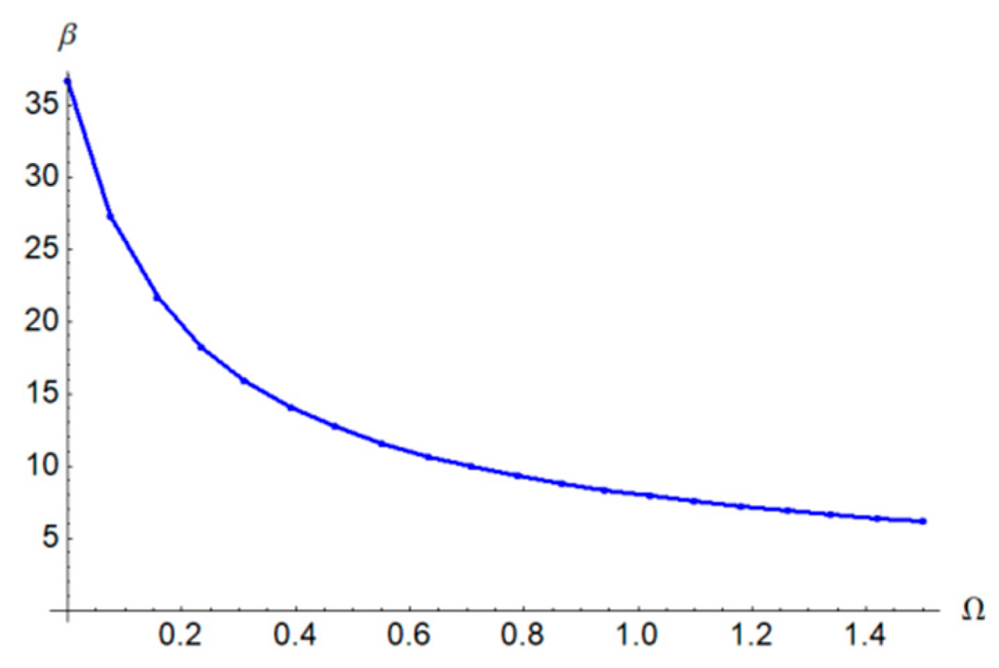
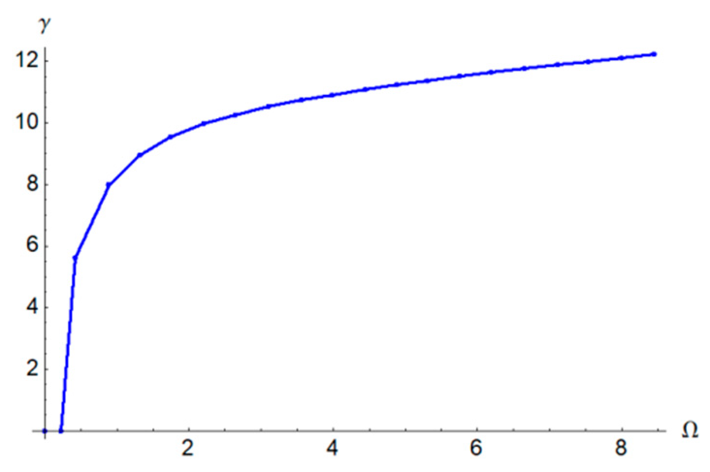
In
Figure 5,
Figure 6 and
Figure 7 are graphically presented the rotor characteristics on the parametric plane
,
and
, respectively, for
β = 0.4,
γ = 0.3,
ξ1 = 0.2 and
ξ2 = 0.2 obtained from Equation (60).
Based on the Hopf bifurcation theory, to obtain one pair of conjugate purely imaginary eigenvalues of the Jacobian matrix, substituting
into Equation (57), we have
with the condition
where
A0,
A1,
A2 and
A3 are given by Equation (A11).
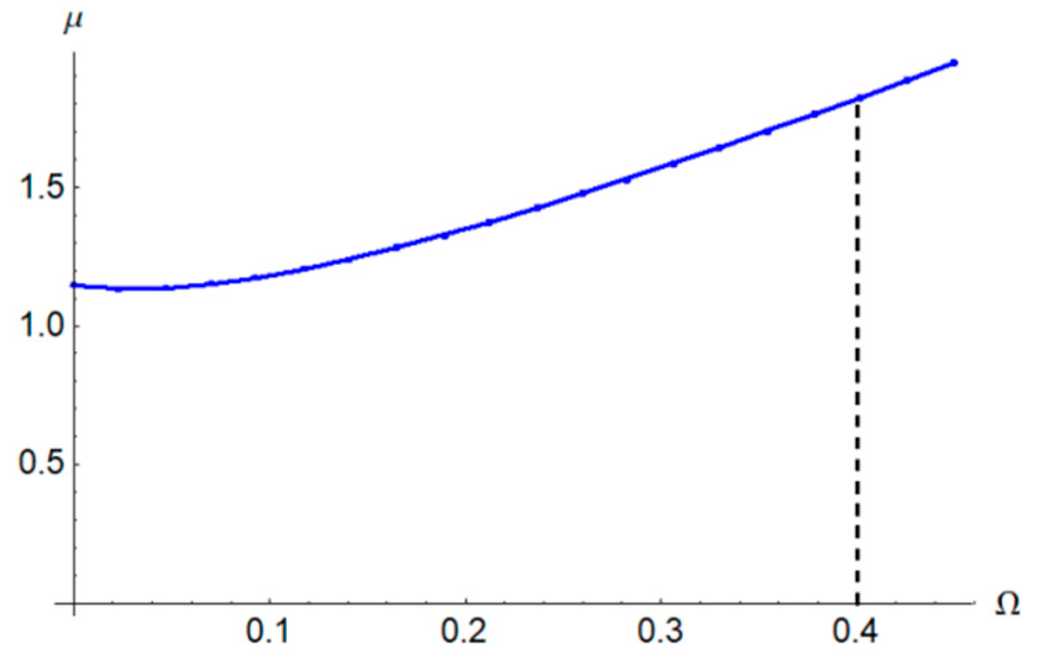
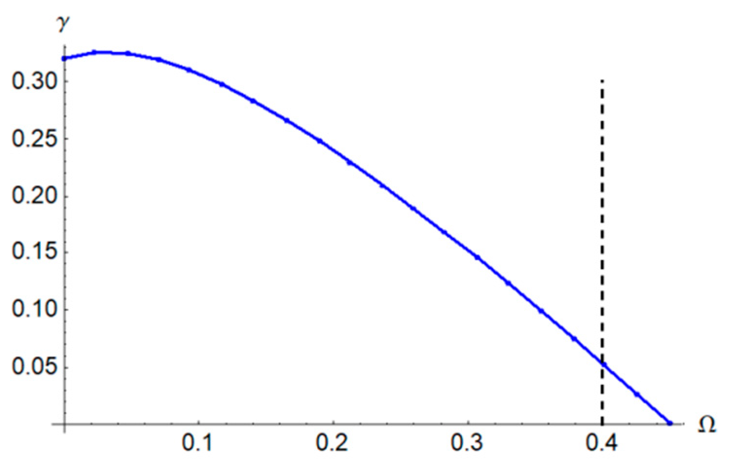
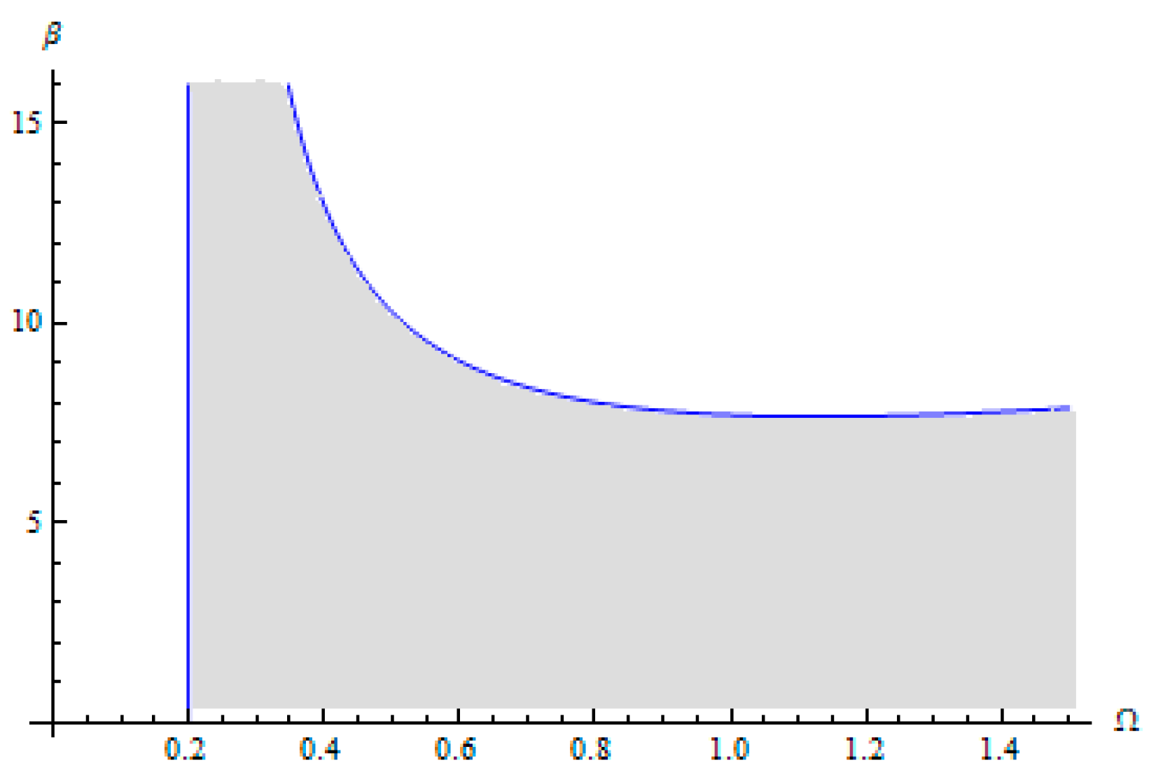
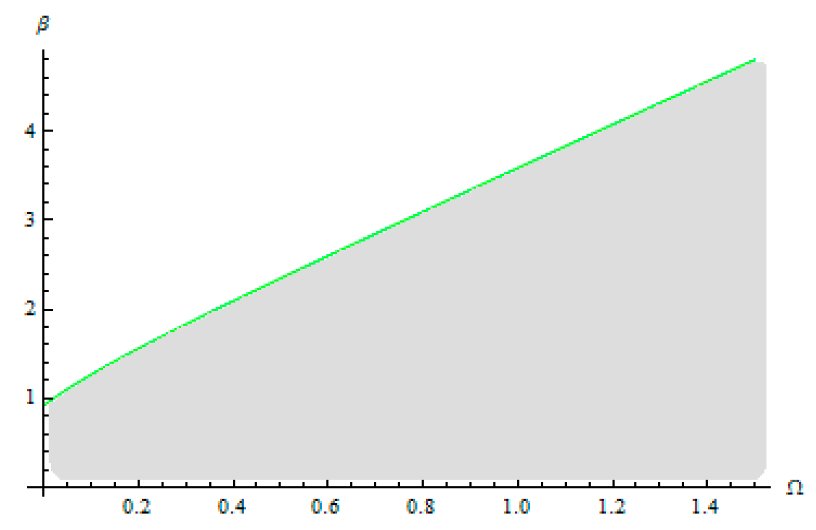
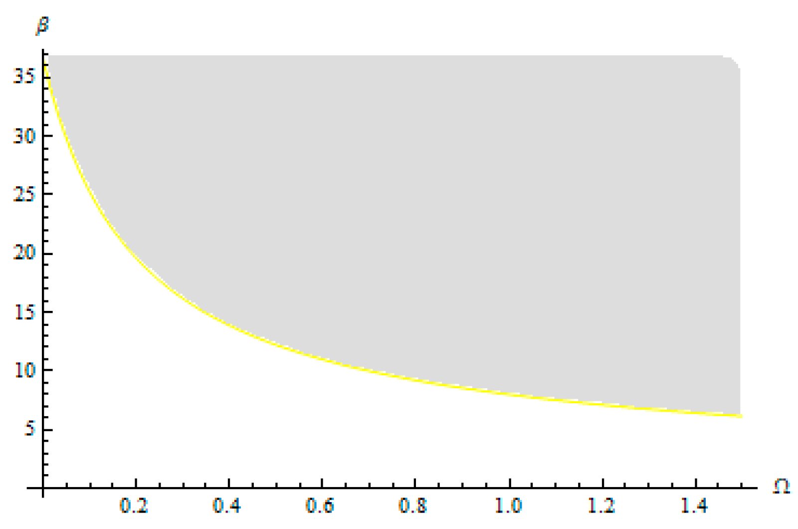
Figure 8,
Figure 9 and
Figure 10 describe the Hopf bifurcation condition of the annular solutions by dividing the region of the annular rub solutions into an area with a stable annular rub solution (below the curve) and an area with unstable annular solution (above the curve). In these figures, the Hopf bifurcation condition and Hopf bifurcation boundary of the full annular solution, respectively, are functions of the rotor frequency Ω and friction coefficient
μ (
Figure 8) and, respectively, the coefficient
β (
Figure 9) and the coefficient γ (
Figure 10).
The Hopf bifurcation boundary of the full annular solution is numerically solved. The boundary of Hopf bifurcation reveals the transition from synchronous full annular rub motion to partial rub motion [
9,
18].
In what follows, we will study a particular case, having in view the conditions of the stability (63) with
Ai,
i = 0,1,2,3 given by Equation (A11). We consider
Due to the fact that
Ao > 0 and
A3 > 0, the conditions (59) are reduced to
6. Conclusions
An important common fault of the rotating machinery is the impact rub, which can lead to the failure of the mechanism. The rub-impact phenomena with nonlinear behavior are among the normal concerns in this field of rotor dynamics.
In this work, the stability of the full annular rub solutions of a complex nonlinear Jeffcott rotor with rotor–stator clearance, the dry friction damper with effects of viscous damping and gyroscopic moment and cross-coupling stiffness coefficients are studied.
The full annular force is analytically and numerically investigated. The model allows for synchronous response and exhibits a typical jump phenomenon. The Routh–Hurwitz criteria are used to establish the stability of the synchronous full annular rub and to obtain the bifurcation boundaries. By variation of the different parameters, the static bifurcation, Hopf bifurcation or saddle-node bifurcation may occur. Numerical investigations were applied to analyze the effects of damping, friction and nonlinearity in the study of stable regions for the conditions of stability.
The novelty and the main contribution of this paper lie in the analytical approximation solution based on the Optimal Auxiliary Functions Method (OAFM), an analytical technique proposed by the authors. The OAFM proves to be a powerful nonlinear tool for solving nonlinear vibration problems since it is effective, explicit and very accurate, rapidly converging to the exact solution using only the first iteration. We obtained for the first time explicit and highly accurate analytical solutions to the considered problem. It is worth emphasizing that every nonlinear differential equation is reduced to only two linear differential equations. This avoids the great difficulties that appear in solving complicated nonlinear differential equations, such as those considered in this paper, and implicitly accelerates the convergence of the approximate analytical solutions. The proposed technique is based upon the original construction of the solutions by means of so-called auxiliary functions, which are another element of novelty, and a moderate number of convergence-control parameters. These parameters lead to high precision when comparing our approximate analytical solutions with numerical integration results. We have great freedom to choose the auxiliary functions, and the optimal values of the convergence-control parameters are determined by means of rigorous mathematical procedures. Let us note that the construction of the linear operator, the auxiliary functions and the convergence-control assurance technique are the most powerful strengths, which guarantee the success of the application of OAFM to solve complicated nonlinear differential equations. Our approach does not need restricting hypotheses (such as the presence of small parameters), as is the case for other analytical methods. On the other hand, we can write that the shortcomings could appear at a large number of degrees of freedom because of cumbersome calculations.
Author Contributions
Conceptualization, V.M. and N.H.; methodology, V.M. and N.H.; software, N.H.; validation, V.M. and N.H.; formal analysis, V.M.; investigation, V.M. and N.H.; resources, N.H.; data curation, V.M. and N.H.; writing—original draft preparation, V.M. and N.H.; writing—review and editing, V.M. and N.H.; visualization, N.H.; supervision, N.H.; project administration, V.M. and N.H.; funding acquisition, N.H. All authors have read and agreed to the published version of the manuscript.
Funding
This research received no external funding.
Data Availability Statement
All data are presented within the paper.
Acknowledgments
The authors would like to thank the reviewers for their valuable comments and helpful suggestions.
Conflicts of Interest
The authors declare no conflict of interest.
Appendix B
The expressions of the coefficients that appear in Equations (A4) and (A5):
References
- Yamamoto, T. On the vibrations of a shaft supported by bearing having radial clearances. Trans. Jpn. Soc. Mech. Eng. 1955, 21, 186–192. [Google Scholar] [CrossRef]
- Ehrich, F.F. Higher-order subharmonic response of high-speed rotors in bearing clearance. ASME J. Vib. Acoust. 1988, 110, 9–16. [Google Scholar] [CrossRef]
- Black, H.F. Interaction of a whirling rotor with a vibrating stator across a clearance annulus. Int. J. Mech. Eng. Sci. 1968, 10, 1–12. [Google Scholar] [CrossRef]
- Muszinska, A. Synchronous self-excited rotor vibration caused by a full annular rub. In Machinery Dynamics 8th Seminar; Canadian Machinery Association: Halifax, NS, Canada, 1984; pp. 22.1–22.21. [Google Scholar]
- Childs, D.W. Fractional-frequency rotor motion due to nonsymmetric clearance effects. Trans. ASME J. Eng. Power. 1982, 104, 533–541. [Google Scholar] [CrossRef]
- Bently, D.E.; Goldman, P.; Yu, J.J. Full annular rub in mechanical seals. Part II. Analytical study. Int. J. Rotating Mach. 2002, 8, 329–336. [Google Scholar] [CrossRef]
- Jiang, J.; Ulbrich, H. Dynamics and stability of rotor stator systems with rubs. In Proceedings of the ASME, Expo 2000, Munich, Germany, 8–11 May 2000. [Google Scholar]
- Yabuno, H.; Kashimura, T.; Inoue, T.; Ishida, Y. Nonlinear normal modes and primary resonance of horizontally supported Jeffcot rotor. Nonlin. Dyn. 2011, 66, 377–387. [Google Scholar] [CrossRef]
- Zhang, H.B.; Chen, Y.S. Bifurcation analysis on full annular rub of a nonlinear rotor system. Sci. China Tech. Sci. 2011, 54, 1977–1985. [Google Scholar] [CrossRef]
- Jeng, J.D.; Hsu, L.; Hun, C.W.; Chu, C.Y. Identification for bifurcation and responses of rub-impacting rotor system. Procedia Eng. 2014, 79, 369–377. [Google Scholar] [CrossRef][Green Version]
- Hou, L.; Chen, Y.; Cao, Q. Nonlinear vibration phenomenon of an aircraft rub-impact rotor system due to hovering flight. Commun. Nonlinear Sci. Numer. Simulat. 2014, 19, 286–297. [Google Scholar] [CrossRef]
- Yang, L.; Zhang, J.; Cao, Y. Uncertainty representation and quantification for a nonlinear rotor/stator system with mixed uncertainties. J. Vibroeng. 2016, 18, 4836–4851. [Google Scholar] [CrossRef]
- Liang, B.L.H.; Shu, C.Y.; Lei, H.; Yong, Z.Z. Periodic response analysis of a frequency/time domain technique. Sci. China Technol. Sci. 2016, 59, 1717–1729. [Google Scholar]
- Yang, Y.; Wang, Y.; Gao, X. Nonlinear analysis of a rub-impact rotor with random stiffness under random excitation. Adv. Mech. Eng. 2016, 8, 1–12. [Google Scholar] [CrossRef]
- Fu, C.; Zhen, D.; Yang, Y.; Gu, F.; Ball, A. Effects of bounded uncertainties on the dynamic characteristics of an overhung rotor system with rubbing fault. Energies 2019, 12, 4365. [Google Scholar] [CrossRef]
- Hong, J.; Yu, P.; Zhang, D.; Ma, Y. Nonlinear dynamic analysis using the complex nonlinear modes for a rotor system with an additional constraint due to rub-impact. Mech. Syst. Signal Process. 2018, 118, 443–461. [Google Scholar] [CrossRef]
- Saeed, N.A.; Awwad, E.M.; Maarouf, A.; Fark, H.M.H.; Alturki, F.A.; Awrejcewicz, J. Rub-impact force induces periodic, quasiperiodic and chaotic motions of a controlled asymmetric rotor system. Shock Vib. 2021, 2021, 1800022. [Google Scholar] [CrossRef]
- Huang, Z.; Tan, J.; Lu, X. Phase difference and stability of a shaft mounted a dry friction damper: Effects of viscous internal damping and gyroscopic moment. Adv. Mech. Eng. 2021, 13, 1–17. [Google Scholar] [CrossRef]
- Nan, G.; Zhu, Y.; Zhang, Y.; Guo, W. Nonlinear dynamic analysis of rotor-bearing system with cubic nonlinearity. Shock Vib. 2021, 2021, 8878319. [Google Scholar] [CrossRef]
- Herisanu, N.; Marinca, V. An efficientanalytical approach to investigate the dynamics of a misaligned multirotor system. Mathematics 2020, 8, 1083. [Google Scholar] [CrossRef]
- Herisanu, N.; Marinca, V.; Madescu, G. Application of the Optimal Auxiliary Functions Method to a permanent magnet synchronous generator. Int. J. Nonlin. Sci. Numer. Simul. 2019, 20, 399–406. [Google Scholar] [CrossRef]
- Herisanu, N.; Marinca, V.; Madescu, G.; Dragan, F. Dynamic response of a permanent magnet synchronous generator to a wind gust. Energies 2019, 12, 915. [Google Scholar] [CrossRef]
- Marinca, B.; Marinca, V. Approximate analytical solution for thin film flow of a fourth-grade fluid down a vertical cylinder. Proceed Rom. Acad. Ser. A 2018, 20, 69–76. [Google Scholar]
- Herisanu, N.; Marinca, V. A solution procedure combining analytical and numerical approaches to investigate a two-degree of freedom vibro-impact oscillator. Mathematics 2021, 9, 1374. [Google Scholar] [CrossRef]
- Marinca, B.; Marinca, V.; Bogdan, C. Dynamics of SEIR epidemic model by Optimal Auxiliary Functions Method. Chaos Solitons Fractals 2021, 147, 110949. [Google Scholar] [CrossRef]
- Marinca, V.; Herisanu, N. An optimal iteration method with application to the Thomas-Fermi equation. Cent. Eur. J. Phys. 2011, 9, 891–895. [Google Scholar] [CrossRef]
- Abramovitz, M.; Stegun, I.A. Handbook of Mathematical Functions; Dover Publications: New York, NY, USA, 1983. [Google Scholar]
| Publisher’s Note: MDPI stays neutral with regard to jurisdictional claims in published maps and institutional affiliations. |
© 2021 by the authors. Licensee MDPI, Basel, Switzerland. This article is an open access article distributed under the terms and conditions of the Creative Commons Attribution (CC BY) license (https://creativecommons.org/licenses/by/4.0/).

