1. Introduction
According to recent studies, a clear reduction in the reservoir of commonly used fossil fuels will soon begin to be perceptible within the next decades [
1,
2]. The alternative is to use renewable sources: wind energy, solar energy, tidal energy, hydroelectric energy, geothermal energy, or ambient heat [
3,
4]. Their use has many benefits, including reducing the pollutant emission into the atmosphere and reducing the greenhouse effect [
5,
6].
At present, we can observe great development of the subject related to solar technology. However, this has only taken place in the development of solar collectors and system design [
7,
8,
9]. Manufacturers of solar systems most often have to propose new absorbers, different insulation materials, improved glazing, or completely new designs of solar collectors. It is very rare to hear anything about changes, improvements, and proposals for new solutions in the sphere of solar system control [
9,
10]. Some studies have used different control methods, but these methods are not the focus of the research [
11,
12]. Research papers on the control in solar thermal systems are mostly of a review nature [
13,
14].
When the subject of control in solar heating systems is raised, the research object is usually only the collector and not the whole system. Many analyses have already been made and many models of solar collectors have been created, which have enabled the achievement of a very high technological advancement in this field. However, few researchers are interested in using such advanced tools to optimise the control of such a system [
14,
15,
16].
It turns out that a well-programmed controller in combination with a circulating heat pump from a branded manufacturer works so efficiently that practically no research has been conducted on new ways of control in solar heating systems [
14,
17,
18]. As can be seen from the literature analysis, the method of control in solar systems does not depend in any way on the level of technological advancement of the collector [
19].
The functions realised by the controller are as follows [
20]:
pump operation control (or pump and valve),
supervision and operation of the solar system,
collector overheating and frost protection,
possibility to connect an additional device: circulating pump, electric heater or to give a signal to a central heating boiler in order to fire it up.
The most popular commercial solution used nowadays is the control based on a controller, which based on external signals of the temperatures of the working medium on the collector and the storage tank, calculates the difference of their values—after this it is referred to as “deltaT” [
21,
22]. The controller adjusts the appropriate mass flow rate to the value of this parameter to maintain a constant temperature difference. The most commonly used procedure increases the speed with which the working medium is pumped into the system in proportion to the difference between the temperatures at the collector and the tank. Some constructors recommend their own characteristics based on intuition [
23,
24].
Such a solution also carries several disadvantages. First, the creation of universal pump operation characteristics is not possible due to the number of parameters and variables in the solar system. Besides, the selection of the pump cut-in and cut-out values cannot disregard the full specification of the system to be controlled [
25,
26,
27].
The second commonly used method is the ON-OFF control mode. The solar controller controls the operation of the pump group in a binary manner. It generates either maximum output or no output at all. This method requires specifying a temperature at which the flow is forced. The pump circulates the medium from the solar collectors to the domestic hot water tank when this value is reached. This method of control results in constant system oscillations and temperature fluctuations at the system output [
28]. One way to reduce these fluctuations is to lower the start point of the pump group, but this has the side effect of increasing the pump switching frequency [
29]. Unfortunately, this reduces the lifetime of the control elements and significantly worsens the reliability and lifetime of the whole system [
30,
31].
The problem with these currently used control methods is that they allow the phenomenon of thermal drift to occur. This phenomenon consists of the outflow of the accumulated thermal energy from the water reservoirs to the solar collector loops. This phenomenon is mainly observed under high heat loads. The lack of information related to temperatures on the coil makes it impossible to eliminate this phenomenon.
Based on the experience gained during research on control systems for solar thermal systems, an improved control system was proposed called Indirect Proportional Control (IPC). Classical control in solar thermal systems is based on the measurement of two temperatures (collector–tank), whereas the principle of operation of the proposed control system is based on the use of additional information from the third temperature sensor shown in
Figure 1b. The circulation pump control depends on the temperature difference of the solar collector and tank temperature, but this time the tank temperature is described by the inlet and outlet exchanger coil temperatures. This allows some additional information to be included. The first of these relates to the parameters of the water stored in the tank. The tank temperature is indirectly measured by temperature sensors on the solar exchanger coil. This makes it possible to control the energy transferred to the storage water. Another additional information provided to the control system is the level of heat losses in the hydraulic loop of the solar panel.
This article is divided into six sections. The remainder of the paper is organised as follows:
Section 2 presents the description of the control methods that have been compared. The test stand and the method of conducting the research are described in
Section 3. The obtained results are presented in
Section 4, while
Section 5 contains a discussion of the obtained results. The article ends with the conclusions presented in
Section 6.
2. Subject of the Study
This paper focuses on an analysis of three control methods in solar heating systems. Proportional, ON-OFF, and IPC have been tested experimentally.
Experimental studies were carried out under natural conditions between spring 2019 and autumn 2020. Three solar controllers with different control algorithms were used during the experimental studies. The experimental investigations were each time preceded by the determination of the initial thermodynamic conditions of the test system. The temperature of the working medium was cooled down to Tinit 20 ± 2 °C in order to eliminate the influence of the initial conditions on the test results. During the outdoor tests, the temperatures at the outlet and inlet to the solar collector array, the medium temperature at the inlet, outlet, and inside the water tank, as well as the ambient temperature of the solar collector array were recorded. In addition, the values of global solar radiation intensity, wind speed, relative humidity, and pressure and mass flow rate of the working medium were also recorded. The measurement data were recorded at a frequency of 1 Hz and stored as a data matrix for each measurement day.
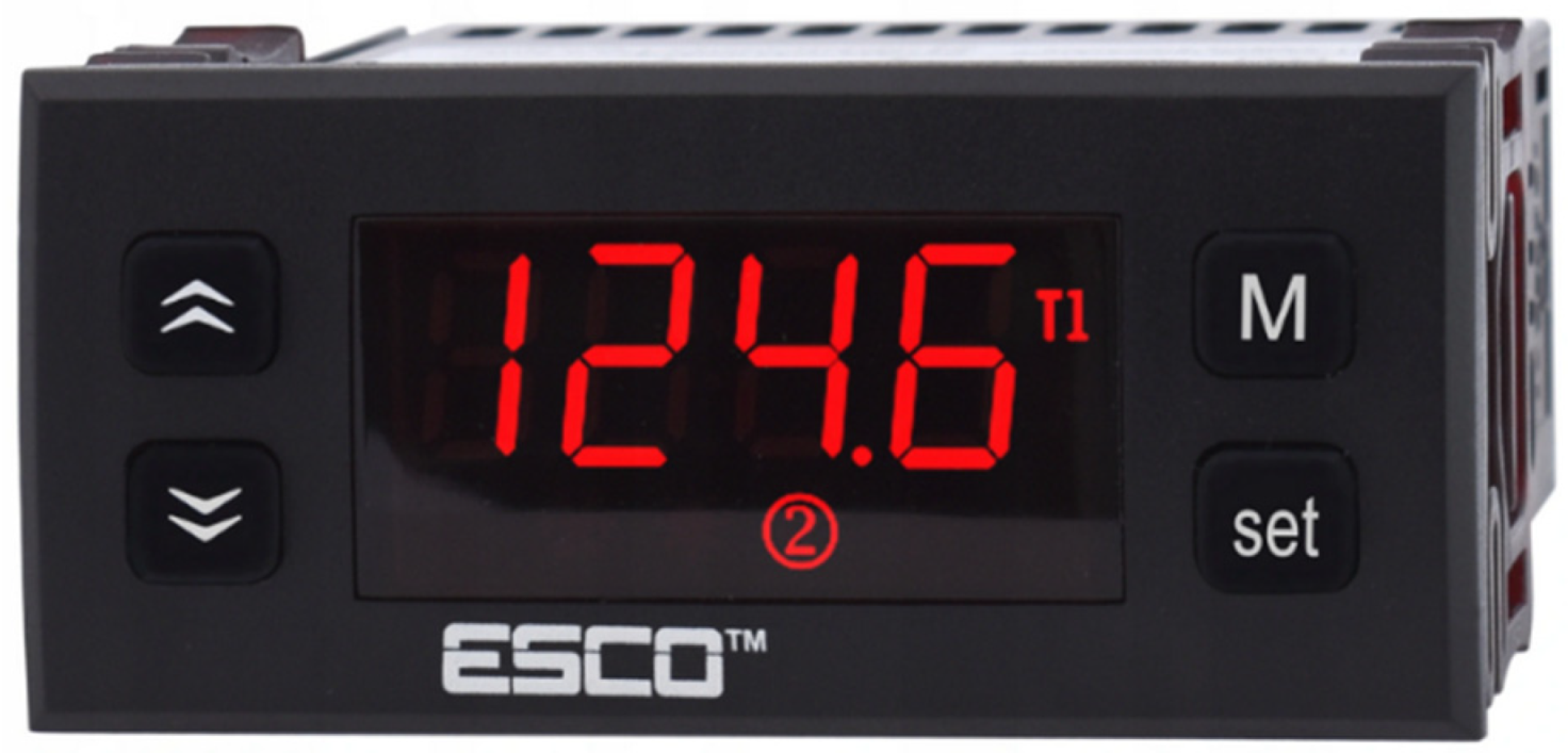
Tests in ON-OFF operation mode were carried out using the ESCO PT-20+ controller (
Figure 2).
It is a basic differential controller with a measuring range of −50 +370 °C cooperating with Pt100 sensors. The controller enables temperature regulation in heating systems with an accuracy of ±0.5 °C. The basic module of the device is a 16 A 3.6 kW relay with a durability of 100 thousand cycles.
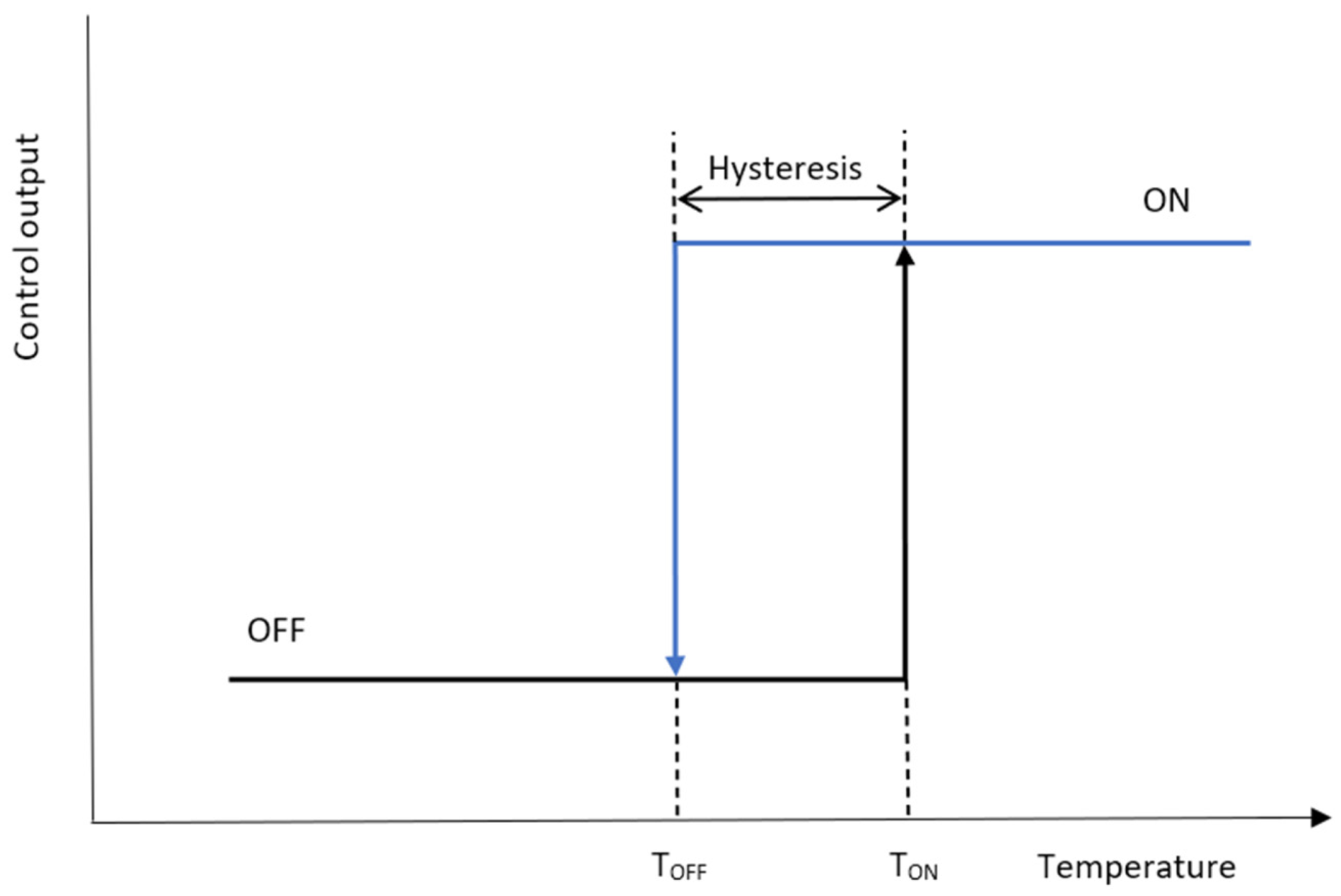
The simplicity is the main reason for choosing the ON-OFF control. It consists in defining the threshold after which the controller activates the hydraulic pump with the maximum value. The operation diagram is shown in
Figure 3.
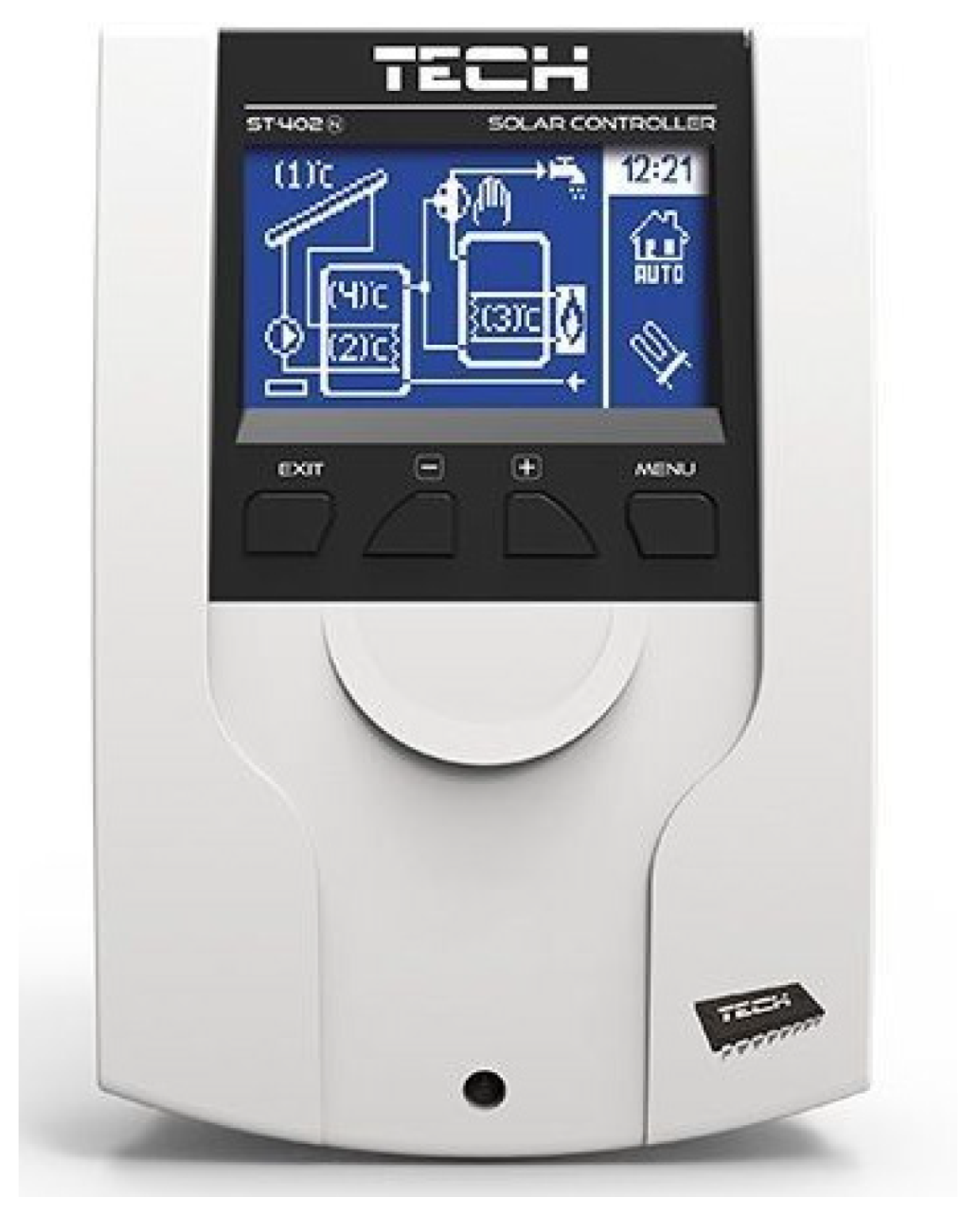
Proportional mode control was implemented using the Tech ST-402n solar controller (
Figure 4). It is a thermoregulator for operating a solar collector system, controlling the main pump based on temperature measurements on the collector and in the accumulation tank. It is possible to connect an additional device namely a circulating pump, an electric heater or to give a signal to a central heating boiler in order to fire it up. It allows adjusting the temperature in the range of −8 °C to 90 °C. It cooperates with two Pt1000 temperature sensors.
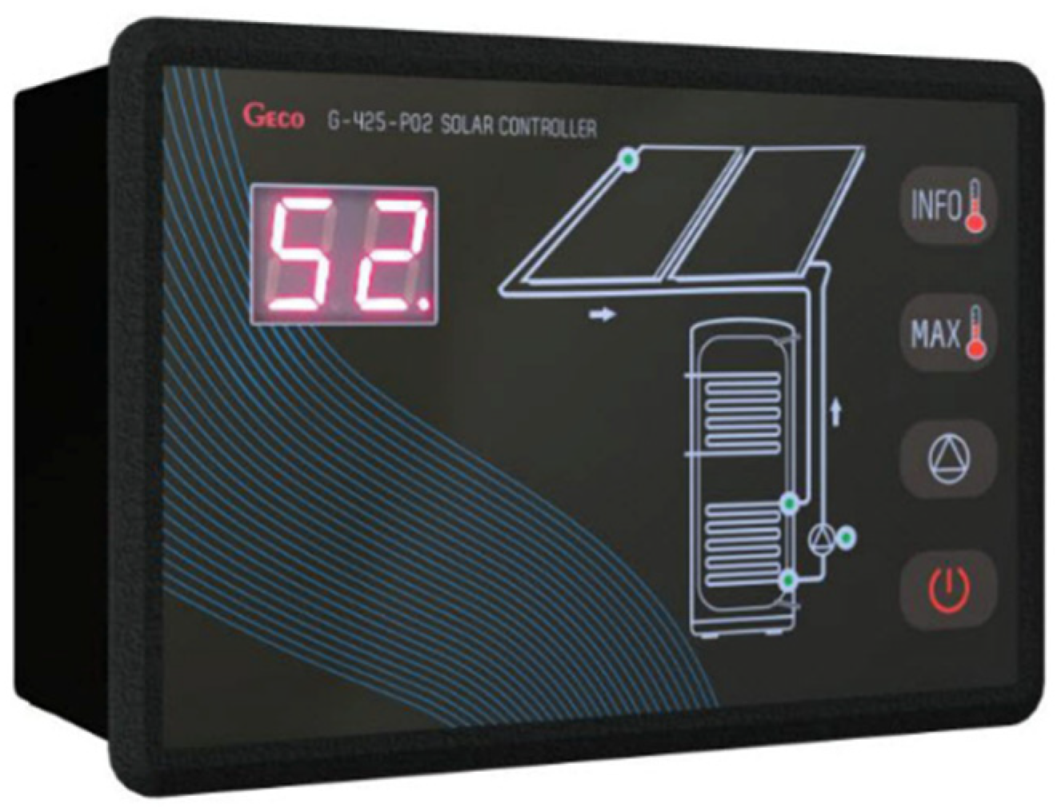
The control of the developed IPC method was carried out using the G-425-P01 Geco controller (
Figure 5). Controlling the efficiency of the circulation pump is carried out smoothly depending on the heat transfer capacity through the coil of the DHW heater. For this purpose, the controller cooperates with three Pt1000 temperature sensors, constantly analysing the variation of temperatures in the solar collectors and the coil’s supply and return.
The proportional controller allows the output to be controlled in the range of 0–100% power. Unlike the ON-OFF, the proportional controller adjusts the output to keep the process stable at the set point.
All three solar system controllers were used equally during the experimental study. Then, the measurement data related to weather conditions were compared using the author’s method of classification of measurement days presented in [
32,
33]. Based on the classification of the measuring days, a comparison of the results of the individual control units was carried out.
3. Experimental Setup
The experimental investigations were carried out on a test stand for solar collectors located at the University of Koszalin [
34]. The stand was constructed to measure the thermal efficiency of the solar thermal system [
35]. The research was conducted between May 2019 and September 2020. The main goal was to analyse the control methods in solar hot water heating systems and provide data related to the evaluation of control methods in solar heating systems.
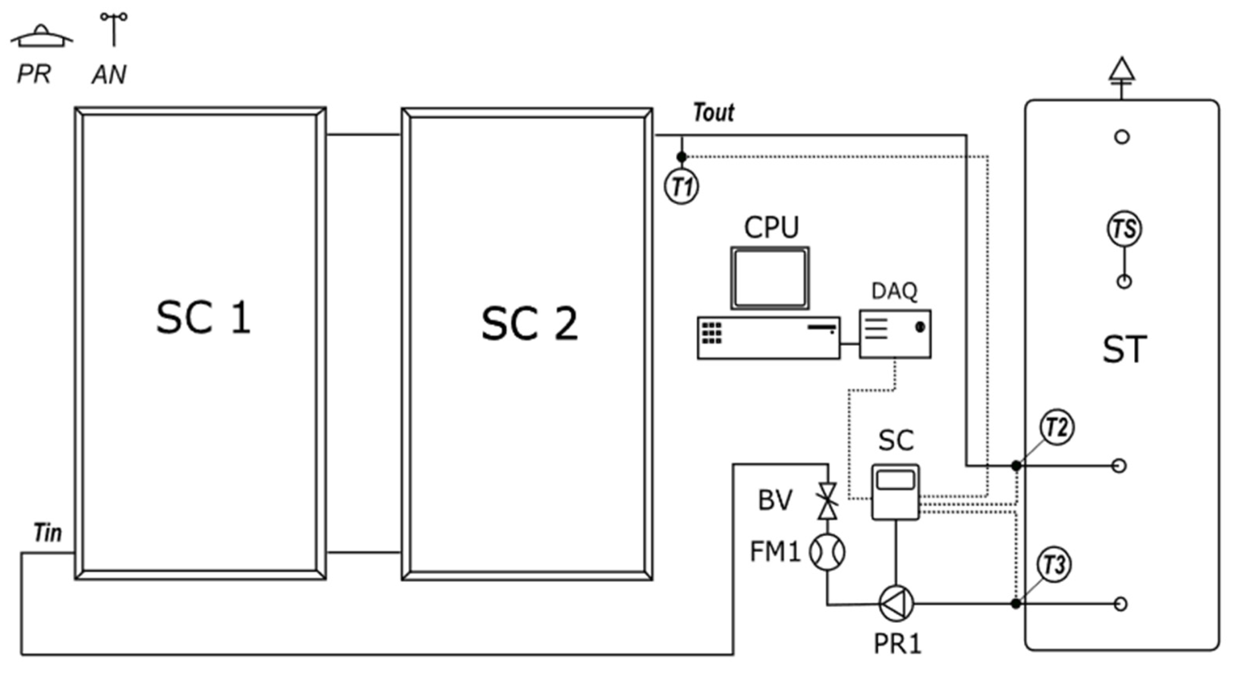
The test stand consists of three mutually cooperating hydraulic circuits: the main circuit, the auxiliary circuit for external reheating of the medium, and the auxiliary circuit for cooling the working medium (
Figure 6). A water storage tank (ST) with a capacity of 200 L is used to store and prepare the working medium. The water tank on the test stand is equipped with special hydraulic circuits to prevent heat stratification. Additionally, there is a measuring platform in the form of a measuring system (DAQ) made by National Instruments and a computer (CPU), allowing for archiving the collected data. The location of the temperature sensors is also shown in the diagram.
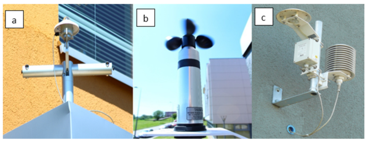
A first-class DeltaOhm pyranometer(PR), model LP PYRA-02, was used to acquire data on the total solar radiation (
Figure 7a). The wind speed was measured with a 3-armed cup rotor anemometer (AN) manufactured by LAMBRECHT, model 14577 (
Figure 7b).
Four-wire RTD sensors were used to measure the temperature of the working medium. This configuration of RTD sensors eliminates potential differences in circuit resistance due to differences in lengths, diameters, and materials. This resulted in measurement accuracy of ±0.1. To measure relative humidity, an HD9008TR transmitter was used (
Figure 7c). The humidity sensor is a capacitor with a dielectric made of a polymer with hygroscopic properties. The signal from the sensor changes proportionally to the changes in relative air humidity. The technical specifications of all sensors are presented in
Table 1,
Table 2,
Table 3 and
Table 4.
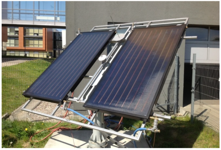
An array consisting of two flat plate solar collectors (KSH-2.0 from Kospel S.A.—
Figure 8) with a total gross area of 4.54 m
2 was installed in the hydraulic system. Basic data on the collectors used during the study are given in
Table 5.
The working fluid circulation in the solar system is forced by a Grunndffos model circulating pump shown in
Figure 9. It is supplied with 230 V AC mains voltage. It has an electronically commutated impeller and a PWM control input. This makes it compatible with solar controllers with PWM control output as well as with differential relay thermostats.
During the experimental tests of the solar controllers, there was no thermal energy consumption from the system. The effectiveness of the control algorithm was evaluated based on the final temperature of the working medium in the storage tank. At the end of the measurement day, the data were recorded, and the hydraulic system was cooled down to the initial conditions. At the same time, the solar controller was replaced with another one from the tested group. In the process of research work, the orientation of the solar collector array was fixed to the southern azimuth and the angle of inclination in relation to the horizon plane B = 40°.
4. Exploratory Measurements of Selected Controllers
As indicated in the literature, most of the control cases in solar systems depend on the temperature difference between the solar collector and the water tank. RTDs (Resistive Temperature Detector) are the most commonly used sensors.
To know the exact operating characteristics of the controllers, a method was developed to simulate the temperature difference between these resistive sensors. For this purpose, a multi-turn potentiometer POT-2218M2-5K with a resistance of 5 kΩ was used. It is a 10-turn model, which allows precise resistance setting due to its linear characteristics. Additionally, a 1 kΩ resistor was added to it. With the help of this element, the temperature change on the collector was simulated. Higher resistance set on the adjustable resistor, which is a potentiometer, resulted in a higher collector medium temperature reading on the controller. The second sensor (from the storage tank) was placed under isolated steady-state conditions for a fixed reference point. A resistor element with a resistance simulating a temperature of 40° by an RTD sensor replaced the second sensor (from the storage tank).
The use of resistive elements allowed the performance characteristics to be tested. On each tested controller, the measurements were started from the equilibrium state between the temperature of the medium in the collector and the temperature of the medium in the tank. This temperature difference was increased by one degree by changing the resistance of the potentiometer. Then, for each deltaT (collector–tank temperature difference) obtained, the flow velocity of the medium flowing through the collector was measured with the MPP-600 flowmeter included in the test stand.
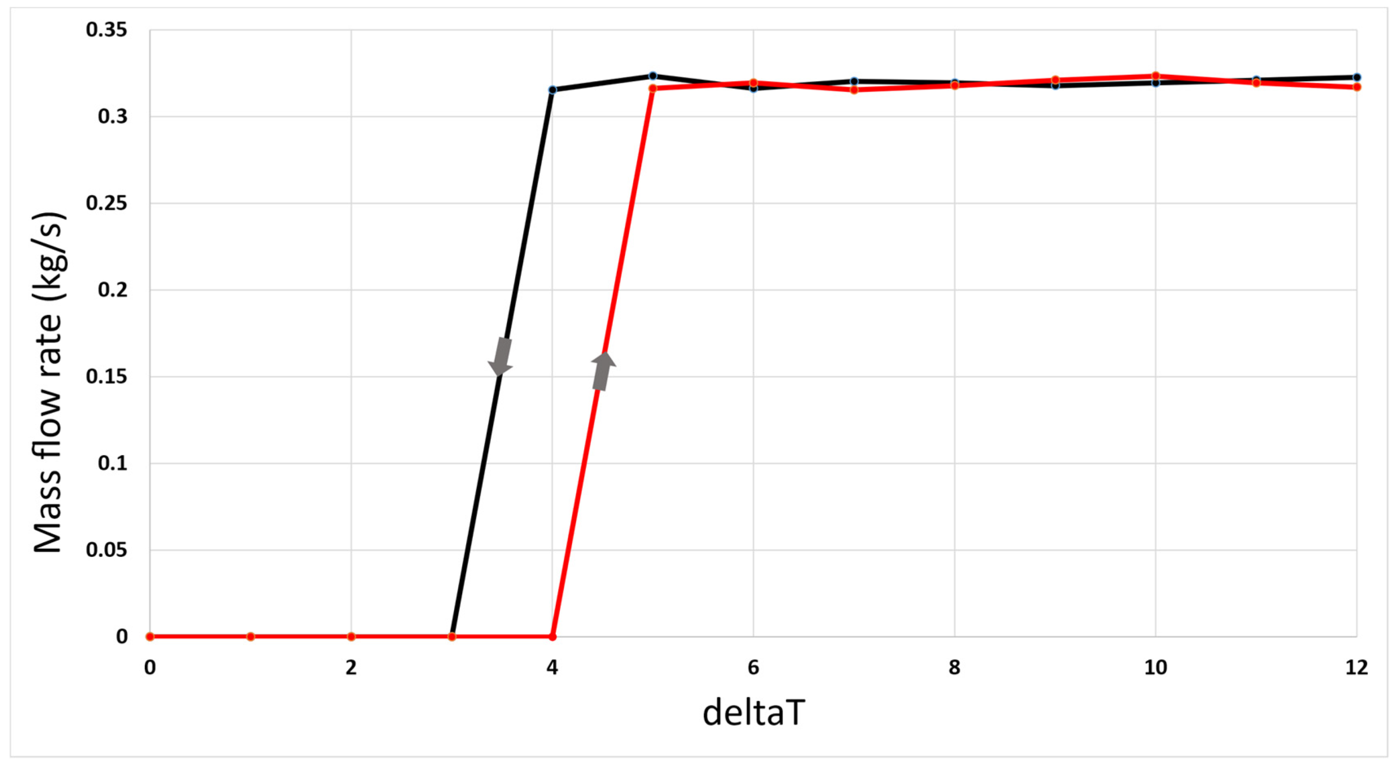
The first measured characteristic of the speed of the working medium as a function of temperature difference referred to the ESCO PT-20 + controller. This is a differential thermostat that operates the pump in ON-OFF mode. The controller makes it possible to set the values for activation and deactivation of the pump. The measurement results of the velocity characteristic as a function of the deltaT temperature difference are presented in
Figure 10.
As shown in
Figure 10, after the switch-ON threshold, the pump is started at maximum power output. The resulting flow velocity of the working medium was 4 m/s in the flow meter, which results in a mass flow rate of 0.11 kg/s in the collector array.
The switch-ON threshold (TON = 5 °C) is set higher than the switch-OFF threshold (TOFF = 3 °C). Such a procedure allows the system to be effectively protected against short-term pump cycles called short-cycling.
Before testing the characteristics of the Tech ST-420n proportional controller, the switch-ON threshold and switch-OFF threshold were configured to the same values as the ON-OFF controller. The characteristics of the proportional controller are shown in
Figure 11.
In proportional control, when the switch-ON threshold value is exceeded, the pump starts forcing the system’s flow at Vf 0.6 m/s (mf = 60 kg/s). A further increase in the value of the deltaT parameter causes a proportional increase in the speed of the working medium in the system. This relation is linear until the saturation value vs = 1.6 m/s is reached. The maximum velocity Vsp = 1.6 m/s realised by this proportional counter-controller is lower than the maximum velocity of the ON-OFF counter-controller Vsof = 4 m/s. As with the previous controller, setting different values of the switch-ON threshold and switch-OFF threshold causes a control hysteresis.
The last examination was on the characteristics of the IPC controller. This controller also allows for the determination of the start-up and shut-down conditions of the pump. Starting the pump requires two independent conditions (1):
In contrast to classical controllers, the collector–tank temperature difference is not the only start-up criterion of the system. It is also necessary to achieve the required temperature difference between the input and output of the solar exchanger coil. The characteristic of the IPC controller is shown in
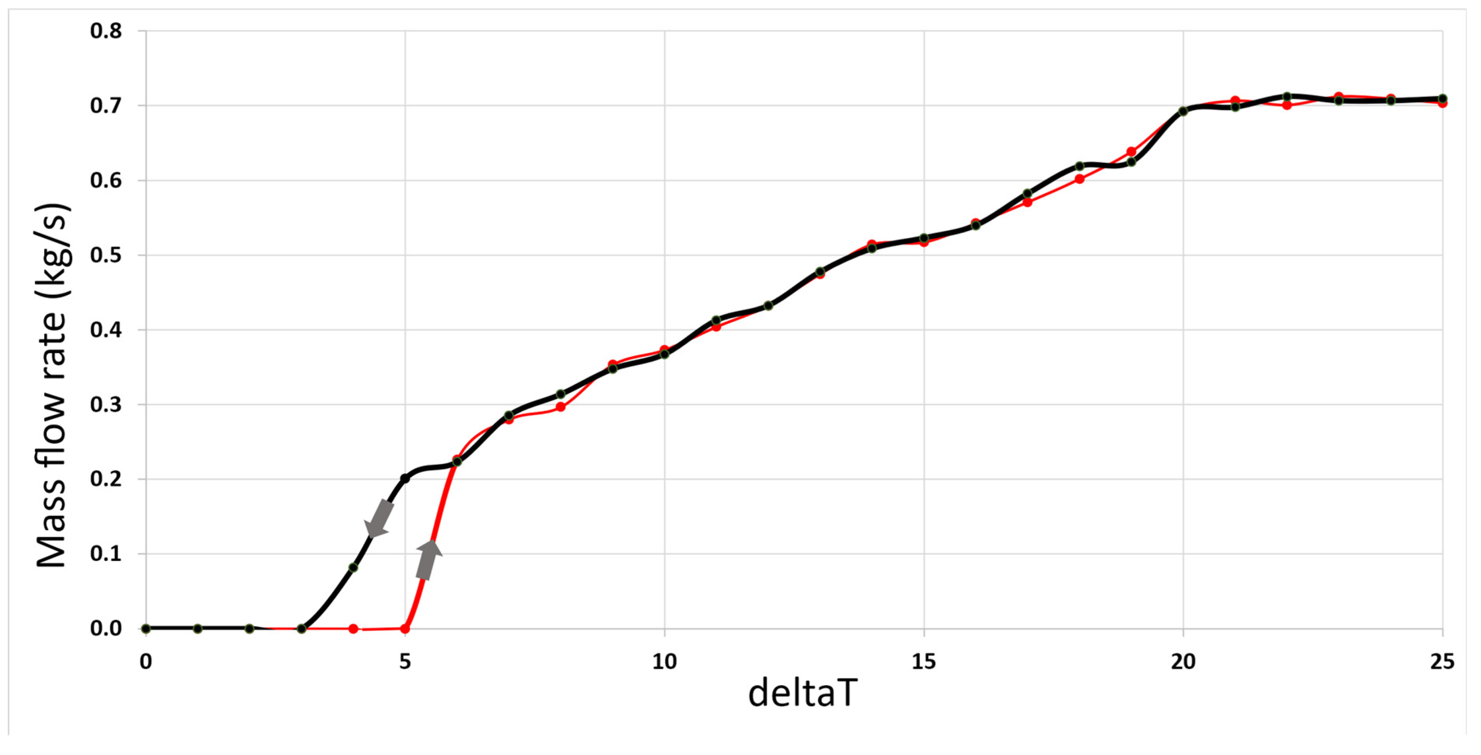
Figure 12.
When the start-up conditions are met, the controller adjusts the pump speed according to the temperature difference between the collector outlet and the solar exchanger coil outlet. For parameter deltaT = 6, a 10% PWM signal filling is programmed, resulting in a mass flow rate of the medium of 0.22 kg/s. The maximum pump speed is reached at deltaT = 20 and is 0.7 kg/s. The switch-OFF threshold, as with previous controllers, is set lower than the switch-ON threshold.
5. Results
Comparative studies of control systems in solar thermal systems under natural conditions are hampered by varying meteorological conditions. It is not possible to directly compare system performance for different control methods. The operating conditions of the system are different every day. To be able to compare the efficiency of the selected solar controllers, a clustering method of measurement days was developed and presented in the paper [
32]. This method considers the amount of solar radiation, its variability, temperature, wind speed, and ambient humidity. As a result, it is possible to group the measurement days with similar weather characteristics. The introduction of weather groups enables the operation of the system controlled by different methods to be compared.
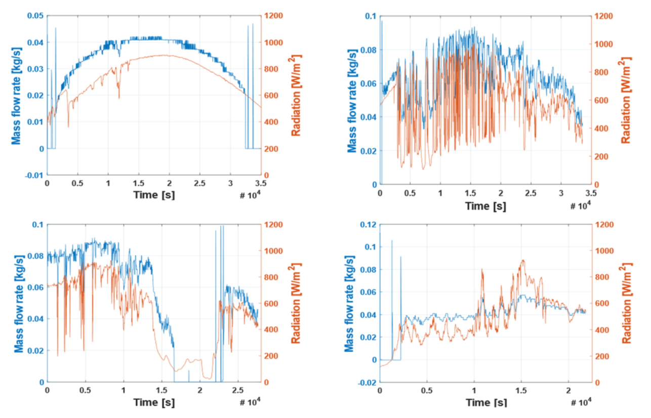
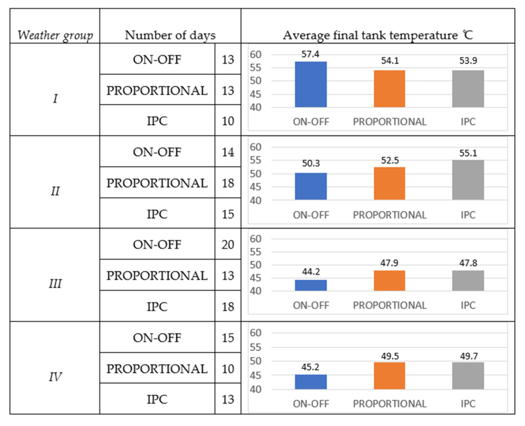
The experimental work resulted in 172 test samples in the form of measurement days, which were divided into four weather groups. These were days with a high and stable value of solar radiation and small interruptions (I), and days with a significant value of solar radiation but with a high rate of radiation changes during the test day (II). Another group consisted of days with a low solar radiation value and high solar operation variability (III). The last group contained days with a low and constant solar radiation value with small interruptions (IV). Four types of weather conditions are shown in
Figure 13. A summary of the field test results is presented in
Figure 14.
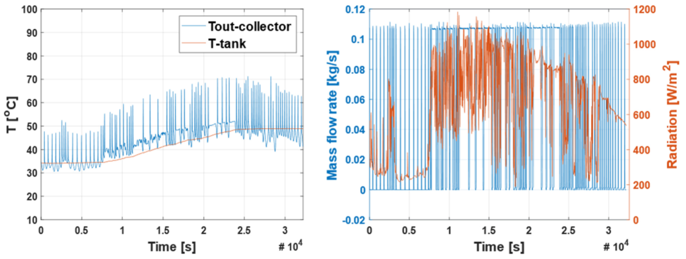
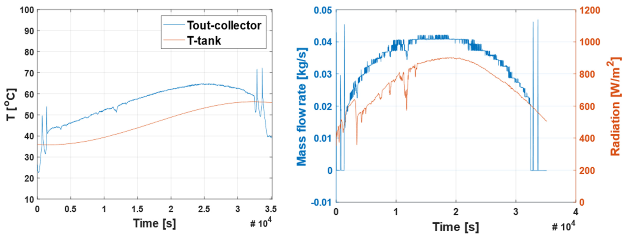
In the first weather group, characterised by stable and intense solar radiation, the highest average final temperatures on the water storage tank were measured for the ON- OFF control. This controller was found to outperform the proportional and IPC by 6%. Based on the experiment, under conditions of undisturbed solar operation, it is most important to efficiently transfer heat from the solar collector array to the water storage tanks. This is achieved through high mass flow rates. In addition, it should be noted that both proportional controllers gave similar results. An example of a day from this group is 12.06, shown in
Figure 15.
The results for the second analysed weather group show a significant reduction in the final medium temperature. This is due to the high solar radiation variability, which characterises this group. It can be observed that under conditions with significant variation of solar irradiance, ON-OFF control is no longer the best choice. The best control under such conditions is the IPC method. The use of the inlet and outlet exchanger coil temperatures during the control process is the reason for this. Under high solar radiation, the energy stored in the tanks reaches the top of the solar heat exchanger. This results in heat drift from the system caused by a standard proportional controller. This is an important problem in terms of designing efficient control methods for solar thermal systems. The proposed solution to prevent heat drift is based on temperature measurements at the interfaces of the solar coil exchanger. If a high temperature is detected at the coil interface, the switch-OFF threshold condition is satisfied, and heat drift is eliminated. The representative of the days included in this group is 3.07 shown in
Figure 16.
The third weather group also contained days with high solar radiation variability, but unlike the previous two groups, the level of solar radiation is significantly lower. As can be seen, the results for the proportional control methods are very similar. The difference is noticeable in the case of the ON-OFF control strategy. Two-state control is clearly inferior when a high variability of weather conditions occurs. When analysing the average results of the temperatures on the storage tank, it is important to note a clear decrease in their values in relation to the two previously discussed weather groups—regardless of the control method. This indicates a strong correlation between the value of solar radiation on a given day and the energy gain. This can be observed in the example of 30.05 shown in
Figure 17.
The last weather group includes days with low but stable solar radiation. It is worth noticing that the ON-OFF control is also clearly worse despite the stability of the radiation. This is caused by the excessive speed of the working medium in the solar system. The inability to adjust the pump speed to the external conditions results in an unprofitable ratio of the incoming heat fluxes from the solar collectors to the heat extracted from the water storage tank. An example of such a day is 22.05, presented in
Figure 18.
In conclusion, energy gains depend more on the level of solar radiation and less on its variability. However, solar radiation variability makes control in solar systems more challenging, and it is one of the factors that should determine the control strategy. Both proportional methods, in conditions with low solar radiation intensity, perform similarly, regardless of variability.
6. Conclusions
This paper focuses on an analysis of three control methods in solar heating systems. In order to study comparative control methods in solar thermal systems, a series of experiments was carried out under natural conditions. The research work was conducted from spring 2019 to autumn 2020 at the solar heating systems laboratory of the Koszalin University of Technology. Measurement data of 172 days were collected and used for the analysis. These were 62 days with ON-OFF control, 54 days with classical proportional control, and 56 days with the IPC control method. Based on the analysis, the following conclusions were formulated:
Under conditions with high daytime solar irradiance and low variability of weather conditions, all control strategies showed comparable results. Moreover, the simplest ON-OFF control method led to the highest thermal energy gains under intense and stable solar radiation conditions. This is due to the characteristic of this method’s high mass flow rate of the medium, which results in the best transfer of heat energy under conditions of high and constant radiation.
Under dynamic sunlight conditions, it becomes necessary to use proportional control methods as they make it possible to achieve higher energy gains under transient conditions. In cases where the amount of solar energy available is significant and when there is no thermal energy consumption, the control process becomes more challenging. While standard proportional controllers tend to cause thermal drifts from the system, methods with additional control parameters (IPC) make more efficient use of high and dynamic solar radiation. This is because proportional methods perform well under dynamic conditions, and the proposed IPC method additionally does not allow heat to escape from the system (thermal drift). This results in better thermal performance.
The presented results confirm the need to develop new control methods for solar thermal systems that consider the different operating conditions of such systems. Advanced adaptive controllers, which adjust the control strategy to different weather conditions, answer this need.
Author Contributions
Conceptualisation, P.Z., K.K., N.C.-G., E.S. and P.G.; methodology, P.Z. and K.K.; software, P.Z. and K.K.; validation, P.Z., K.K. and N.C.-G.; formal analysis, P.Z., K.K., N.C.-G., P.G. and E.S.; resources, P.Z., K.K., N.C.-G. and E.S.; data curation, P.Z. and K.K.; writing—original draft preparation, P.Z. and K.K.; writing—review and editing, P.Z., K.K., N.C.-G., E.S. and P.G.; visualisation, P.Z. and K.K.; supervision, N.C.-G. and E.S.; funding acquisition, E.S. All authors have read and agreed to the published version of the manuscript.
Funding
The article received financial support from the Scientific Council of Civil Engineering and Transport at Warsaw University of Technology.
Institutional Review Board Statement
Not applicable.
Informed Consent Statement
Informed consent was obtained from all subjects involved in the study.
Data Availability Statement
Data are available in a publicly accessible repository.
Acknowledgments
The authors would like to gratefully acknowledge the reviewers that provided helpful comments and insightful suggestions on a draft of the manuscript.
Conflicts of Interest
The authors declare no conflict of interest. The funders had no role in the design of the study; in the collection, analyses, or interpretation of the data; in the writing of the manuscript; or in the decision to publish the results.
References
- Jurasz, J.; Canales, F.A.; Kies, A.; Guezgouz, M.; Beluco, A. A review on the complementarity of renewable energy sources: Concept, metrics, application and future research directions. Sol. Energy 2020, 195, 703–724. [Google Scholar] [CrossRef]
- European Commission. Energy for the Future: RES White Paper for a Community Strategy and Action Plan; Office for Official Publications of the European Communities; European Commission: Luxembourg, 1997; Volume 97, p. 599. [Google Scholar]
- Iqbal, W.; Yumei, H.; Abbas, Q.; Hafeez, M.; Mohsin, M.; Fatima, A.; Jamali, M.A.; Jamali, M.; Siyal, A.; Sohail, N. Assessment of Wind Energy Potential for the Production of Renewable Hydrogen in Sindh Province of Pakistan. Processes 2019, 7, 196. [Google Scholar] [CrossRef]
- Hadjiat, M.M.; Mraoui, A.; Ouali, S.; Kuzgunkaya, E.H.; Salhi, K.; Ait Ouali, A.; Benaouda, N.; Imessad, K. Assessment of geothermal energy use with thermoelectric generator for hydrogen production. Int. J. Hydrog. Energy 2021, 46, 37545–37555. [Google Scholar] [CrossRef]
- Deng, Z.; Cui, S.; Kou, K.; Liang, D.; Shi, X.; Liu, J. Dopant-Free π-Conjugated Hole Transport Materials for Highly Stable and Efficient Perovskite Solar Cells. Front. Chem. 2021, 9, 664504. [Google Scholar] [CrossRef]
- Li, R.; Liu, M.; Matta, S.K.; Hiltunen, A.; Deng, Z.; Wang, C.; Dai, Z.; Russo, S.P.; Vivo, P.; Zhang, H. Sulfonated Dopant-Free Hole-Transport Material Promotes Interfacial Charge Transfer Dynamics for Highly Stable Perovskite Solar Cells. Adv. Sustain. Syst. 2021, 2100244. Available online: https://onlinelibrary.wiley.com/doi/abs/10.1002/adsu.202100244 (accessed on 23 November 2021).
- Kulkarni, M.V.; Deshmukh, D.S.; Shekhawat, S.P. An innovative design approach of hot water storage tank for solar water heating system using artificial neural network. Mater. Today Proc. 2021, 46, 5400–5405. [Google Scholar] [CrossRef]
- Ruelas, A.; Velázquez, N.; Villa-Angulo, C.; Acuña, A.; Rosales, P.; Suastegui, J. A Solar Position Sensor Based on Image Vision. Sensors 2017, 17, 1742. [Google Scholar] [CrossRef]
- Kicsiny, R. Transfer functions of solar heating systems with pipes for dynamic analysis and control design. Solar Energy 2017, 150, 596–607. [Google Scholar] [CrossRef][Green Version]
- Andrzejczyk, R. Experimental Investigation of the Thermal Performance of a Wickless Heat Pipe Operating with Different Fluids: Water, Ethanol, and SES36. Analysis of Influences of Instability Processes at Working Operation Parameters. Energies 2018, 12, 80. [Google Scholar] [CrossRef]
- Alawi, O.A.; Kamar, H.M.; Mallah, A.R.; Mohammed, H.A.; Sabrudin, M.A.S.; Newaz, K.M.S.; Najafi, G.; Yaseen, Z.M. Experimental and Theoretical Analysis of Energy Efficiency in a Flat Plate Solar Collector Using Monolayer Graphene Nanofluids. Sustainability 2021, 13, 5416. [Google Scholar] [CrossRef]
- Martorana, F.; Bonomolo, M.; Leone, G.; Monteleone, F.; Zizzo, G.; Beccali, M. Solar-assisted heat pumps systems for domestic hot water production in small energy communities. Solar Energy 2021, 217, 113–133. [Google Scholar] [CrossRef]
- Duffie, J.A.; Beckman, W.A. Solar Engineering of Thermal Process; John Wiley & Sons: New York, NY, USA, 1991. [Google Scholar]
- Camacho, E.F.; Rubio, F.R.; Berenguel, M.; Valenzuela, L. A survey on control schemes for distributed solar collector fields. Part II: Advanced control approaches. Solar Energy 2007, 81, 1252–1272. [Google Scholar] [CrossRef]
- Azhar, K.M.; Idres, A.H. Analysis of energy savings for residential electrical and solar water heating systems. Case Stud. Therm. Eng. 2021, 27, 101347. [Google Scholar]
- Meena, C.S.; Raj, B.P.; Saini, L.; Agarwal, N.; Ghosh, A. Performance Optimisation of Solar-Assisted Heat Pump System for Water Heating Applications. Energies 2021, 14, 3534. [Google Scholar] [CrossRef]
- Hongbing, C.; Yutong, G.; Haoyu, N.; Xiaoli, Y.; Xilin, C. Optimization and Performance Study of Residential Centralized Solar Domestic Hot Water System. Energy Procedia 2019, 158, 6431–6437. [Google Scholar] [CrossRef]
- Villasmil, W.; Troxler, M.; Hendry, R.; Schuetz, P.; Worlitschek, J. Control strategies of solar heating systems coupled with seasonal thermal energy storage in self-sufficient buildings. J. Energy Storage 2021, 42, 103069. [Google Scholar] [CrossRef]
- Fernández-Seara, J.; Piñeiro, C.; Dopazo, J.A.; Fernandes, F.; Sousa, P.X.B. Experimental analysis of a direct expansion solar assisted heat pump with integral storage tank for domestic water heating under zero solar radiation conditions. Energy Convers. Manag. 2012, 59, 1–8. [Google Scholar] [CrossRef]
- Li, W.T.; Tushar, W.; Yuen, C.; Ng, B.K.K.; Tai, S.; Chew, K.T. Energy efficiency improvement of solar water heating systems—An IoT based commissioning methodology. Energy Build. 2020, 224, 110231. [Google Scholar] [CrossRef]
- Daghigh, R.; Shafieian, A. Theoretical and experimental analysis of thermal performance of a solar water heating system with evacuated tube heat pipe collector. Appl. Therm. Eng. 2016, 103, 1219–1227. [Google Scholar] [CrossRef]
- Budea, S.; Bădescu, V. Improving the Performance of Systems with Solar Water Collectors Used in Domestic Hot Water Production. Energy Procedia 2017, 112, 398–403. [Google Scholar] [CrossRef]
- Araújo, A.; Silva, R. Energy modeling of solar water heating systems with on-off control and thermally stratified storage using a fast computation algorithm. Renew. Energy 2020, 150, 891–906. [Google Scholar] [CrossRef]
- Ertekin, C.; Kulcu, R.; Evrendilek, F. Techno-Economic Analysis of Solar Water Heating Systems inTurkey. Sensors 2008, 8, 1252–1277. [Google Scholar] [CrossRef]
- Obstawski, P.; Bakoń, T.; Czekalski, D. Comparison of Solar Collector Testing Methods—Theory and Practice. Processes 2020, 8, 1340. [Google Scholar] [CrossRef]
- Kicsiny, R.; Farkas, I. Improved differential control for solar heating systems. Sol. Energy 2012, 86, 3489–3498. [Google Scholar] [CrossRef]
- Kalogirou, S.A. Solar thermal collectors and applications. Prog. Energy Combust. Sci. 2004, 30, 231–295. [Google Scholar] [CrossRef]
- Hassan, A.A.; Elwardany, A.E.; Ookawara, S.; El-Sharkawy, I.I. Performance investigation of a solar-powered adsorption-based trigeneration system for cooling, electricity, and domestic hot water production. Appl. Therm. Eng. 2021, 199, 117553. [Google Scholar] [CrossRef]
- Han, X.; Li, C.; Ma, H. Performance Studies and Energy-Saving Analysis of a Solar Water-Heating System. Processes 2021, 9, 1536. [Google Scholar] [CrossRef]
- Hamed, M.; Fellah, A.; Brahim, A.B. Parametric sensitivity studies on the performance of a flat plate solar collector in transient behawior. Energy Convers. Manag. 2014, 78, 938–947. [Google Scholar] [CrossRef]
- Zhou, X.; Wu, L.; Xiao, G.; Tong, Z.; Li, H. Experimental investigation and economic analysis on a solar pure water and hot water hybrid system. Appl. Therm. Eng. 2021, 195, 117182. [Google Scholar] [CrossRef]
- Znaczko, P.; Kamiński, K.; Zuchniewicz, J. A Correlation Study between Weather Conditions and the Control Strategy of a Solar Water Heating System. In Sustainable Design and Manufacturing 2020, Smart Innovation, Systems and Technologies; Scholz, S.G., Howlett, R.J., Setchi, R., Eds.; Springer: Singapore, 2021; Volume 200. [Google Scholar]
- Kaminski, K.; Znaczko, P.; Lyczko, M.; Krolikowski, T.; Knitter, R. Operational properties investigation of the flat-plate solar collector with poliuretane foam insulation. Procedia Comput. Sci. 2019, 159, 1730–1739. [Google Scholar] [CrossRef]
- Kuczynski, W.; Kaminski, K.; Znaczko, P.; Chamier-Gliszczynski, N.; Piatkowski, P. On the correlation between the geometrical features and thermal efficiency of flat-plate solar collectors. Energies 2021, 14, 261. [Google Scholar] [CrossRef]
- Znaczko, P.; Szczepanski, E.; Kaminski, K.; Chamier-Gliszczynski, N.; Kukulski, J. Experimental diagnosis of the heat pipe solar collector malfunction. A case study. Energies 2021, 14, 3050. [Google Scholar] [CrossRef]
Figure 1.
Diagram of the standard (a) and proposed (b) control system.
Figure 1.
Diagram of the standard (a) and proposed (b) control system.
Figure 2.
ESCO PT-20+ controller.
Figure 2.
ESCO PT-20+ controller.
Figure 3.
The ON-OFF control scheme.
Figure 3.
The ON-OFF control scheme.
Figure 4.
Tech ST-402n solar controller.
Figure 4.
Tech ST-402n solar controller.
Figure 5.
G-425-P01 Geco controller.
Figure 5.
G-425-P01 Geco controller.
Figure 6.
Hydraulic system.
Figure 6.
Hydraulic system.
Figure 7.
Pyranometer (a), anemometer (b), and humidity sensor (c).
Figure 7.
Pyranometer (a), anemometer (b), and humidity sensor (c).
Figure 8.
Outdoor platform with solar flat-plate collectors [
34].
Figure 8.
Outdoor platform with solar flat-plate collectors [
34].
Figure 9.
Grunndffos circulating pump.
Figure 9.
Grunndffos circulating pump.
Figure 10.
Measured ESCO PT-20+ characteristic.
Figure 10.
Measured ESCO PT-20+ characteristic.
Figure 11.
Measured Tech ST-420n characteristic.
Figure 11.
Measured Tech ST-420n characteristic.
Figure 12.
IPC controller characteristic.
Figure 12.
IPC controller characteristic.
Figure 13.
Four types of weather groups.
Figure 13.
Four types of weather groups.
Figure 14.
Summary of measurement data.
Figure 14.
Summary of measurement data.
Figure 15.
Measurement results of 12.06.
Figure 15.
Measurement results of 12.06.
Figure 16.
Measurement results of 3.07.
Figure 16.
Measurement results of 3.07.
Figure 17.
Measurement results of 30.05.
Figure 17.
Measurement results of 30.05.
Figure 18.
Measurement results of 22.05.
Figure 18.
Measurement results of 22.05.
Table 1.
Technical specifications of the pyranometer.
Table 1.
Technical specifications of the pyranometer.
| Transducer | Measuring Range (W/m2) | Sensitivity (µV/W/m2) | Spectral Range (nm) | Time Constant (s) |
|---|
| LP-PYRA-02 | 0 ÷2000 | ±10 | 305 ÷ 2800 | <28 |
Table 2.
Technical specifications of the anemometer.
Table 2.
Technical specifications of the anemometer.
| Transducer | Measuring Range (m/s) | Measurement Accuracy (%) | Measurement Resolution (m/s) |
|---|
| LAMBRECHT 14577 | 0.7 ÷ 50 | ±0.2 | 305 ÷ 2800 |
Table 3.
Technical specification of the PT100 RTD temperature sensor.
Table 3.
Technical specification of the PT100 RTD temperature sensor.
| Transducer | Measurement Card | Measuring Range (K) | Measurement Accuracy (K) | Measurement Resolution (K) |
|---|
| PT100 RTD | NI 9217 | ±120 | ±0.1 | 0.02 |
Table 4.
Technical specification of the meteorological station.
Table 4.
Technical specification of the meteorological station.
| Transducer | Humidity (°C) | Measurement Accuracy (K) | Measurement Resolution (K) |
|---|
| HD9008TR | −40 ÷ 80 | ±0.1 | 0.05 |
Table 5.
Technical specification of the KSH-2.0 collector.
Table 5.
Technical specification of the KSH-2.0 collector.
| Solar Collector Type | Flat-Liquid |
|---|
| Manufacturer/trademark: | KOSPEL S.A./KSH-2.0 |
| Gross area/aperture/absorber: | 2.27/1.98/2.00 (m2) |
| Collector length/width/height: | 2.12/1.1/0.09 (m) |
| Empty collector mass: | 36.5 (kg) |
| Publisher’s Note: MDPI stays neutral with regard to jurisdictional claims in published maps and institutional affiliations. |
© 2021 by the authors. Licensee MDPI, Basel, Switzerland. This article is an open access article distributed under the terms and conditions of the Creative Commons Attribution (CC BY) license (https://creativecommons.org/licenses/by/4.0/).

