
Technology for Improving the Efficiency of Fractured Reservoir Development Using Gel-Forming Compositions


Abstract
:1. Introduction
2. Materials and Methods
- Gelation time—for successful water shut-off operations, the gel must gain strength over a sufficient period to allow for its injection into the reservoir, but not more than 24 h (average down time after the completion of work before the use of the well);
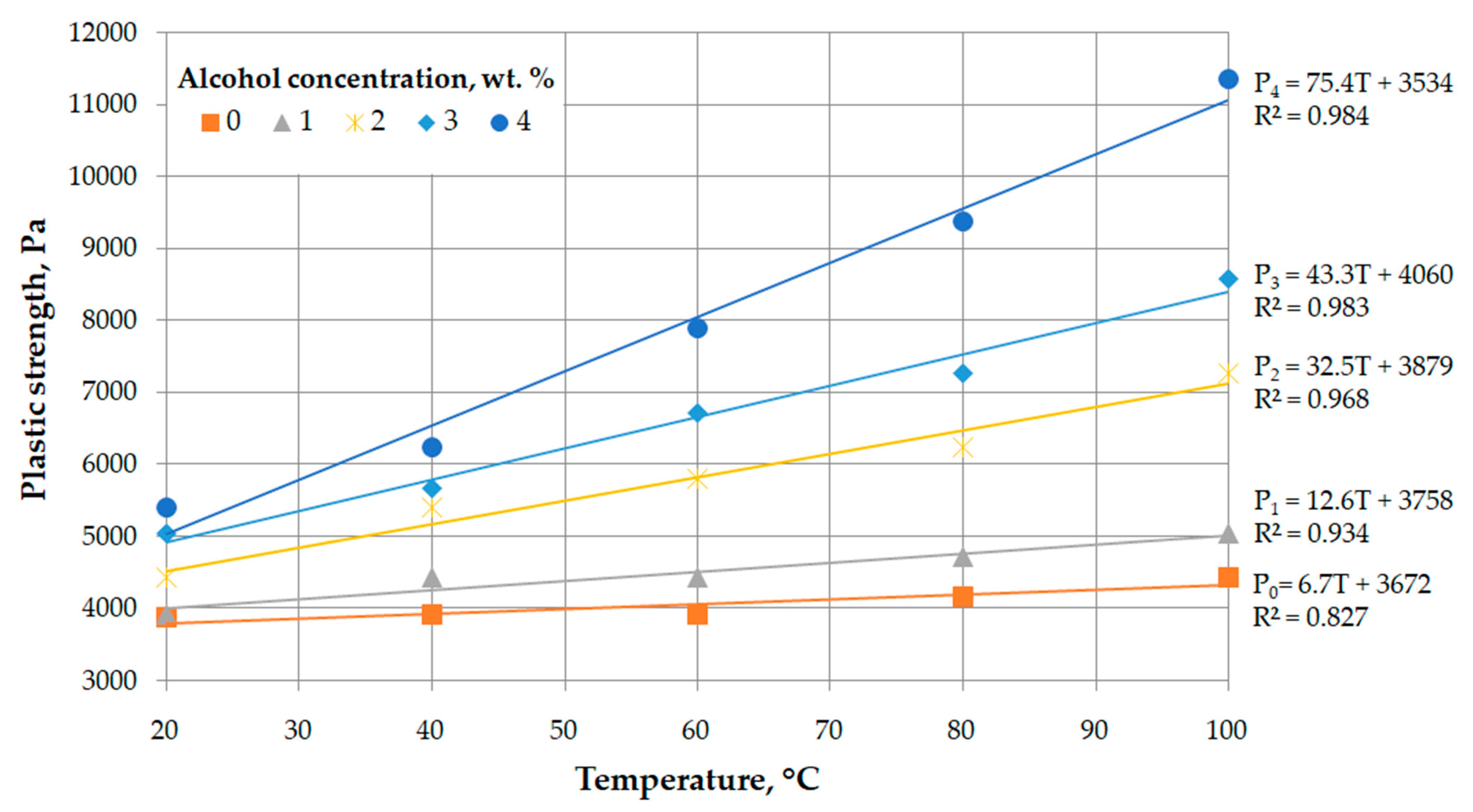
- Plastic strength—a parameter that determines the ability of a gel to resist water breakthrough;
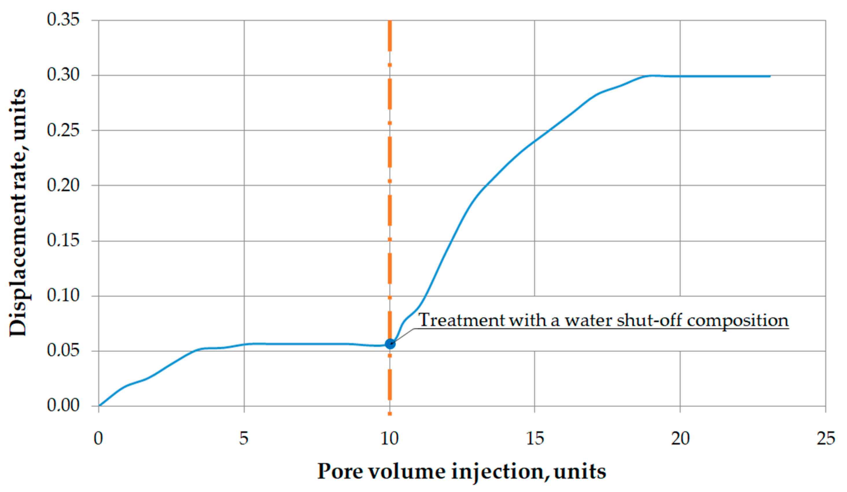
- The ability of the water shut-off composition to reduce the filtration characteristics of water-saturated and highly permeable reservoir systems in order to increase the oil displacement rate.
2.1. Determening Gelation Time
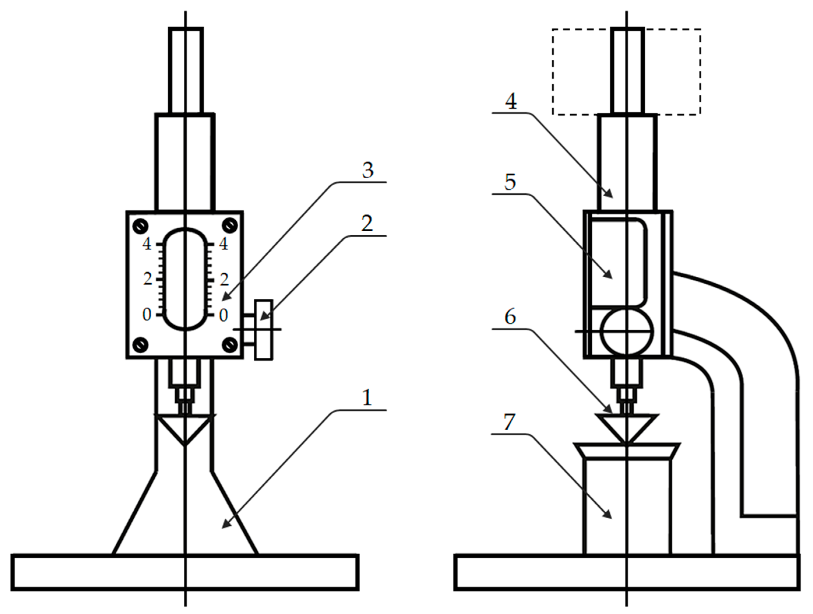
2.2. Determening Plasticstrength
2.3. Filtration Study Methodology
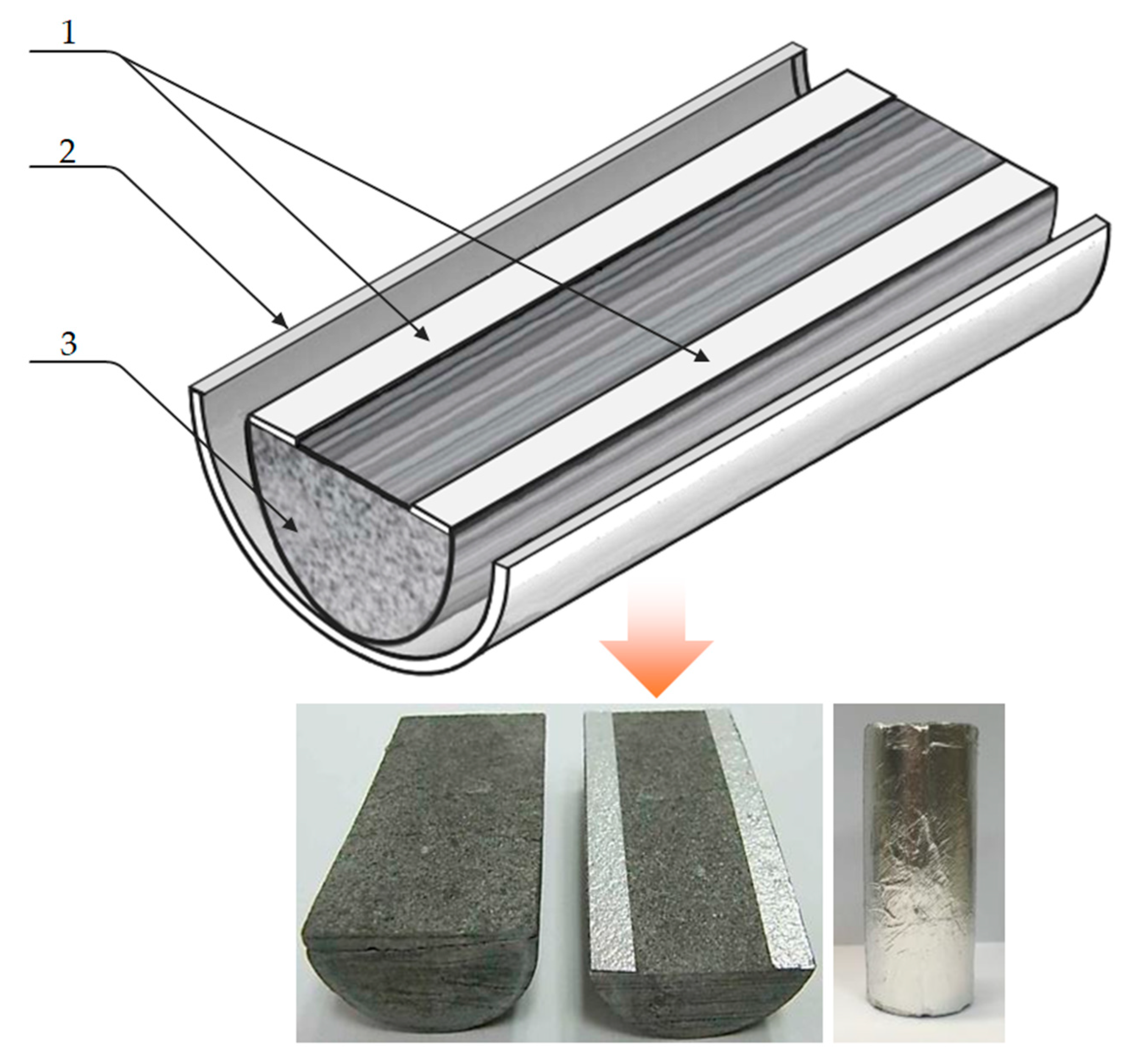
- The core is cut into two identical halves;
- On the surface of the inside cut, two strips of aluminium foil [32] 5 mm wide and 3 layers thick are laid;
- Two parts of the core are fastened and placed in plastic shrink tube and fastened using a heat gun.
2.4. Methodology of Filtration Studies on Natural Core Samples of Pore and Fracture Type
- The prepared natural core sample was saturated under vacuum according to a prepared formation water model. After saturation, the pore volume of the core was determined by weight.
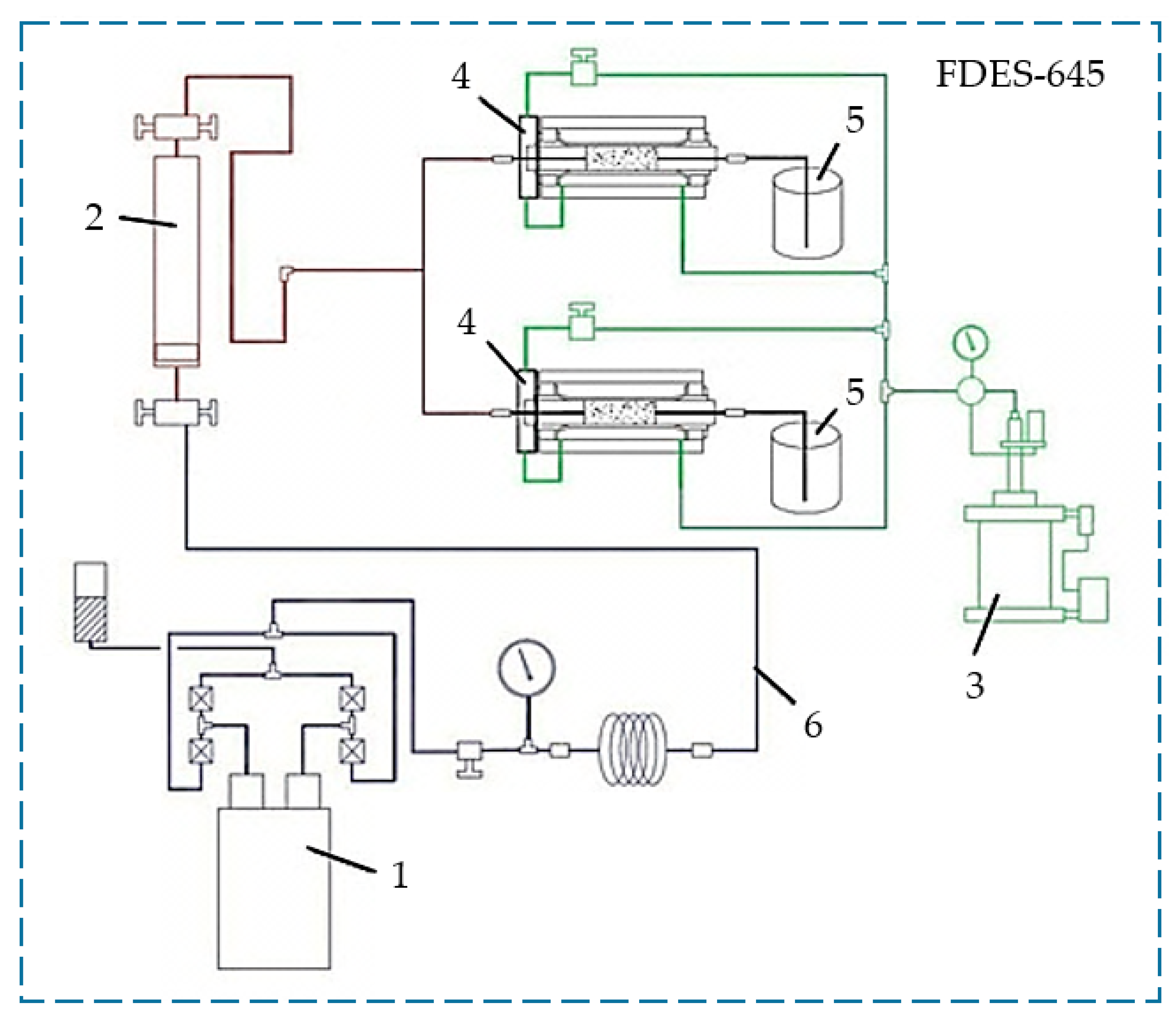
- The saturated core sample was placed into the core holder of the FDES-645 filtration unit, where pressures were created simulating reservoir conditions [33].
- Filtration of water (or oil while modelling the oil-saturated interval of the productive formation) was carried out through the core sample. At the same time, the initial phase permeability of the core to the formation water was measured in a constant flow rate mode until the pressure gradient stabilized at an average reservoir temperature (37 °C) and reservoir pressure (20 MPa). Filtration was carried out in the “forward” direction.
- The investigated water shut-off composition was injected at a constant flow rate. The injection volume of the composition, measured by the weight at the core outlet was five times the pore volume of the core (i.e., the maximum possible at high injection pressures). Filtration was carried out in the “reverse” direction.
- After the shut-off composition was injected into the sample core, the temperature was increased to the average reservoir temperature (37 °C) and the system was maintained in a resting state. The holding time of the system at constant thermobaric conditions averaged 24 h.
- After holding the core sample at rest, the phase permeability with formation water was measured in a constant flow mode until the pressure gradient stabilized. Filtration was carried out in the “forward” direction.
- After measuring the phase permeability at a constant flow rate, a breaker fluid was injected, also at five times the pore volume of the core. Filtration was carried out in the “reverse” direction.
- After the breaker fluid was injected, the final phase permeability was measured at a constant flow rate until the pressure gradient stabilized. Filtration was carried out in the “forward” direction.
- The processing of the coreflood tests was as follows:
- The injection pressure gradient of the water shut-off composition was determined after one fifth and the full pore volumes worth of water had been pumped through;
- The initial shear pressure gradient of the water shut-off composition in the core was determined using water (or oil) at the last stage of the coreflood tests;
- The injection pressure gradient of the breaker fluid was determined after one fifth and the full pore volumes worth of water had been pumped through;
- The injection pressure gradient of water (or oil) was determined at the last stage of the coreflood tests;
- The residual resistance factor of the core sample after was calculated after its treatment with the investigated water shut-off composition:where —residual resistance factor after treatment with a water shut-off composition, unit fraction; —pressure gradient of water (or oil) injection into the core sample before the “isolation” process, Pa/m; —pressure gradient of water (or oil) injection into the core sample after the “isolation” process, Pa/m.
- the maximum resistance of the core sample was calculated after its treatment with the investigated water shut-off composition:where —maximum resistance factor injection of the water shut-off composition, unit fraction; —initial (maximum) gradient of the shear pressure of the gel in the core during water (or oil) filtration, Pa/m.
- the residual resistance factor of the core sample was calculated after its treatment with the d breaker fluid:where —residual resistance factor after injection of the breaker fluid, unit fraction; —pressure gradient of water (or oil) injection into the core sample after injection of the breaker fluid, Pa/m.
2.5. Methodology of Filtration Studies to Determine the Oil Displacement Rate from a Fractured Reservoir
- The prepared core samples are saturated under vacuum with the oil model. After saturation, the pore volume of the core is determined by weight.
- The saturated core samples are placed in core holders, where pressures are generated to simulate reservoir conditions.
- Water is injected simultaneously into both cores at a constant flow rate. At the same time, the volume of injected water and displaced oil from each core sample is measured. The injection of water is stopped after the displaced liquid has fully flushed.
- Five pore volumes of the investigated water shut-off composition are injected simultaneously into both samples of the core at a constant flow rate. In this case, the volume of liquid displaced from each core sample is fixed.
- After the shut-off composition injection process into the core samples, the temperature is brought up to simulate the average formation (37 °C) and the system is maintained in a resting state. The holding time of the system in thermobaric conditions is 24 h on average.
- After holding the core samples at rest, the injection of the water into both samples was repeated until the displaced liquid was completely flushed. The volume of injected water and displaced oil from each core sample were re-determined.
- The oil displacement rate for the fractured-porous reservoir model is calculated by:where —oil displacement rate by water, unitfraction; —volume of oil displaced from core samples, ml; —initial volume of oil in core samples, ml.
3. Results and Discussion
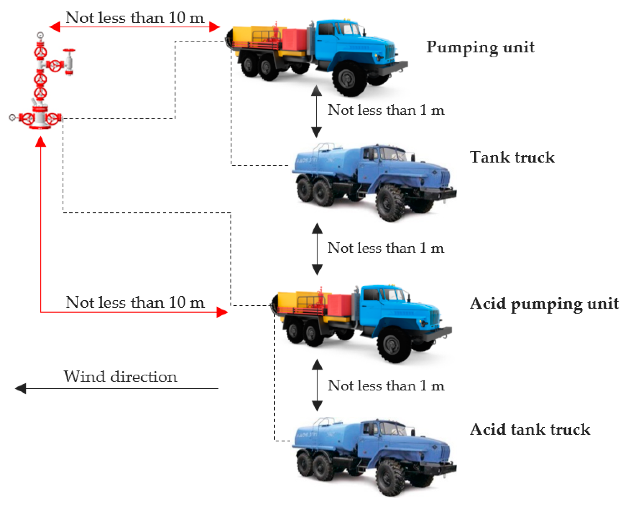
Realization of the Proposed Technology on the Field
- Prior to the work on the well, a set of field geophysical tests is carried out, the results of which are used to determine the technical status of the production string, the mark of the current bottomhole, the inflow profile and the source of water cut in the well, on the basis of which the technological scheme of the work is selected;
- The tubing shoe rises to the interval with increased injectivity; the well is pressurized at 20% higher than the expected injection pressure of the water shut-off composition;
- The required volume of water shut-off composition is calculated;
- Fresh water is injected into the bottomhole formation zone before injection of the composition; injection of a buffer fluid allows the reduction of the concentration of polyvalent metal cations [36] in fluids saturating the bottomhole formation zone, and, as such, to prevent uncontrolled premature precipitation of sediment upon contact between formation water and water shut-off composition;
- The water shut-off composition is injected: to prevent the formation of induced fractures, the water shut-off composition is forced through with water (salinity no more than 20 g/L) with a flow rate not exceeding 80% of the normal injectivity of the well; the low viscosity of the composition (1–15 mPa·s) until the end of the induction period of gelation contributes to easy pumping into the formation and the creation of an extended water shut-off screen;
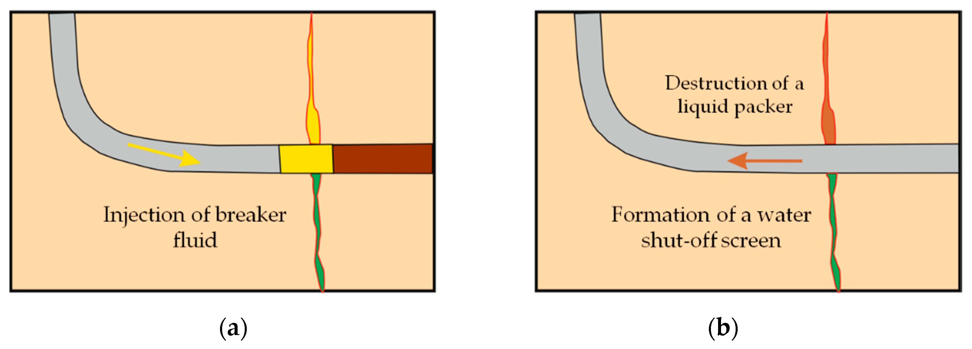
- After the pumping of water shut-off composition into the formation, the wellbore is washed with a fresh water solution and a technological pause is maintained for 3–4 h; at the end of the specified time, a breaker fluid (20% aqueous sodium hydroxide solution) with a volume of 0.1–0.2 m3 per 1 m of watering interval thickness is pumped into the well to clean the wellbore and restore the permeability of oil-saturated zones, then the wellbore is washed again with fresh water from alkali solution.
4. Conclusions
- A physicochemical technology has been developed to improve the efficiency of the development of fractured reservoirs by injecting into the reservoir a water shut-off composition with a wide-range regulated strength and a gel-forming period.
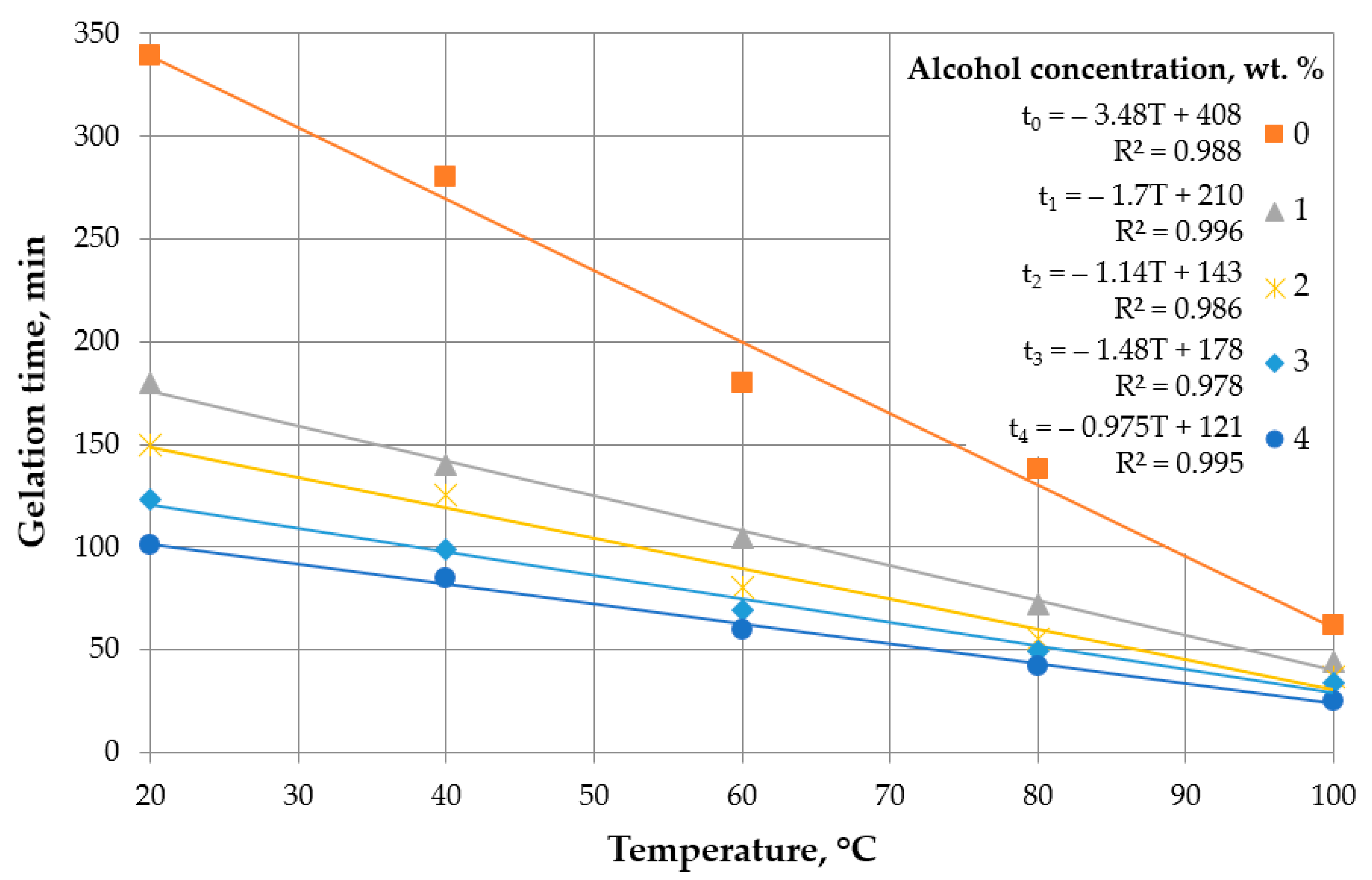
- Technological characteristics are determined depending on the concentration of reagents and temperature.
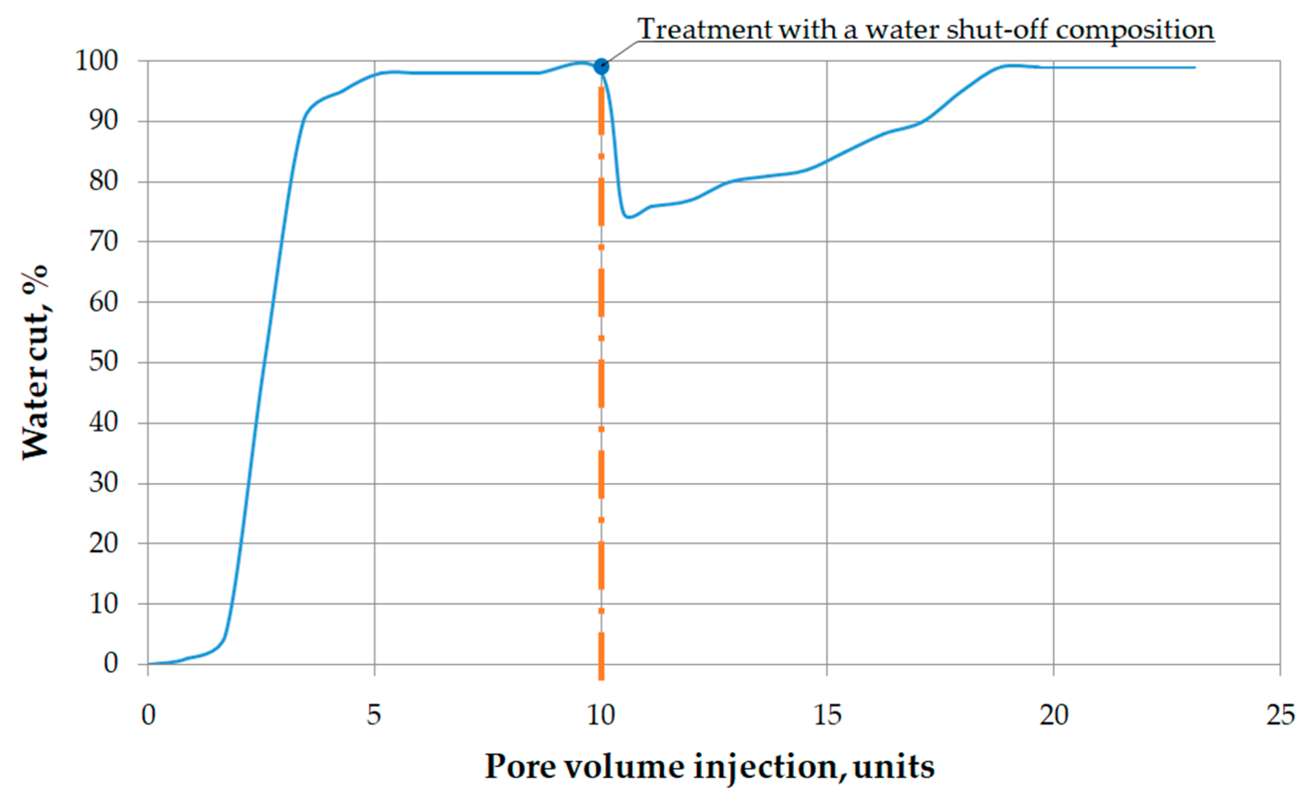
- The developed water shut-off composition effectively reduces the permeability of water-saturated fractures (residual resistance factor is 180 units), while it is not filtered into the pore space.
- According to the results of laboratory studies, the proposed technology allows a reduction in the water cut of the produced products by 24% and an increase in the oil displacement rate by water in a fractured-porous reservoir from 0.07 to 0.3.
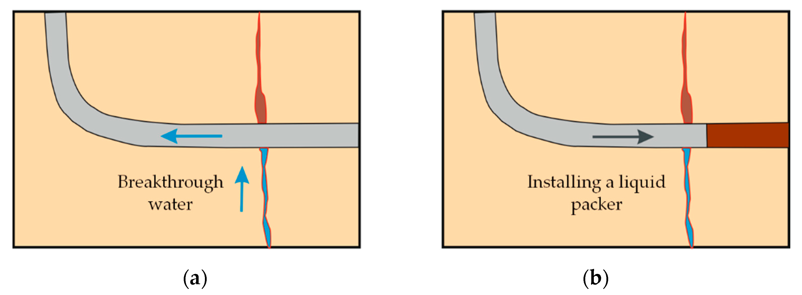
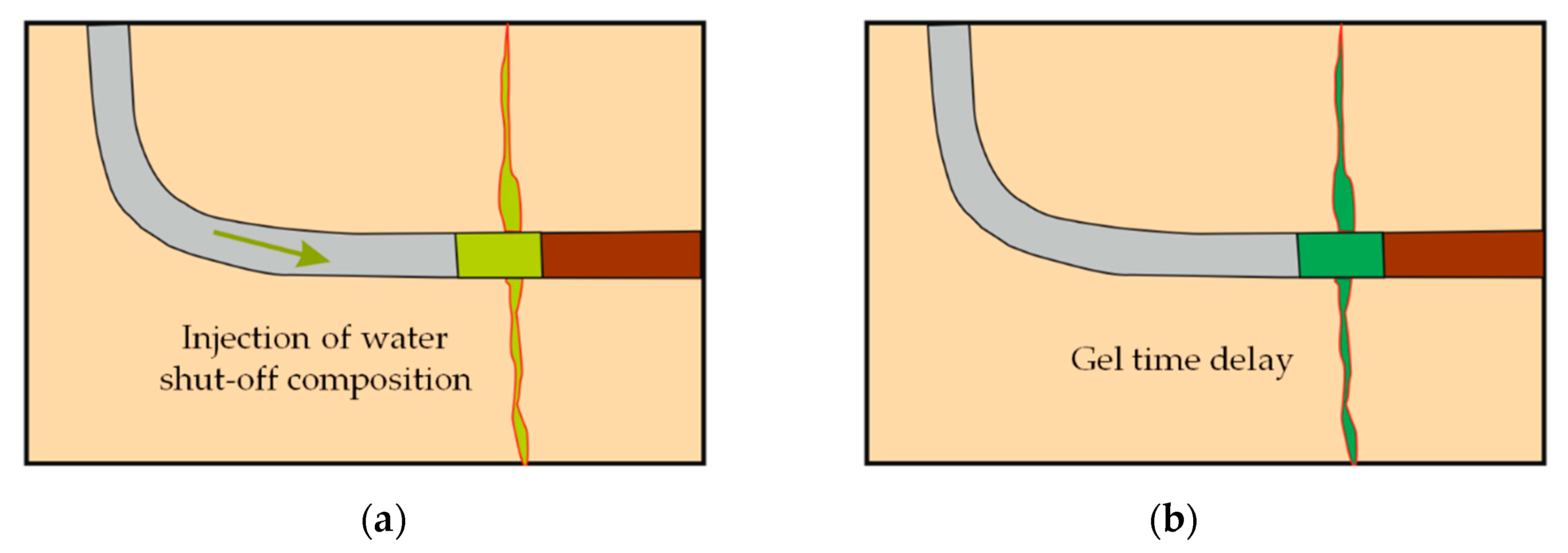
- For operation in horizontal wells, a selective formation stimulation technology with the use of a “liquid packer” has been proposed, which protects the remote part of the wellbore from the action of a water shut-off composition.
5. Patents
Author Contributions
Funding
Institutional Review Board Statement
Informed Consent Statement
Data Availability Statement
Acknowledgments
Conflicts of Interest
References
- Molchanov, A.A.; Ageev, P.G. Implementation of new technology is a reliable method of extracting reserves remaining in hydro-carbon deposits. J. Min. Inst. 2017, 227, 530–539. [Google Scholar]
- Fetisov, V.; Mohammadi, A.H.; Pshenin, V.; Kupavykh, K.; Artyukh, D. Improving the economic efficiency of vapor recovery units at hydrocarbon loading terminals. Oil Gas Sci. Technol. 2021, 76, 38. [Google Scholar] [CrossRef]
- Dvoynikov, M.; Buslaev, G.; Kunshin, A.; Kraslawski, A.; Budovskaya, M. New concepts of hydrogen production and storage in Arctic region. Resources 2021, 10, 3. [Google Scholar] [CrossRef]
- Nikitin, M.N.; Petukhov, A.V. Gel-forming composition on sodium silicate base for water shutoff in complex structure fractured reservoir conditions. Pet. Eng. 2011, 5, 143–154. [Google Scholar]
- Golf-Rakht, T.D. Fundamentals of Fractured Reservoirs Engineering; Elsevier Publishing: Amsterdam, The Netherlands, 1982. [Google Scholar]
- Petukhov, A.V. Theory and Methodology of Studying the Structural-Spatial Zoning of Oil and Gas Fractured Reservoirs; Ukhta State Technical University Press: Ukhta, Russia, 2002. [Google Scholar]
- Reiss, L.H. The Reservoir Engineering Aspects of Fractured Formations; TECHNIP Editions: Paris, France, 1980. [Google Scholar]
- Chernyshov, S.E.; Repina, V.A.; Krysin, N.I.; Macdonald, D.I.M. Improving the efficiency of terrigenous oil-saturated reservoir development by the system of oriented selective slotted channels. J. Min. Inst. 2020, 246, 660–666. [Google Scholar] [CrossRef]
- Jia, H.; Chen, H.; Zhao, J.Z. Development of a highly elastic composite gel through novel intercalated crosslinking method for wellbore temporary plugging in high-temperature reservoirs. SPE J. 2021, 25, 2853–2866. [Google Scholar] [CrossRef]
- Jafarpour, H.; Moghadasi, J.; Khormali, A.; Petrakov, D.; Ashena, R. Increasing the stimulation efficiency of heterogeneous carbonate reservoirs by developing a multi-bached acid system. J. Pet. Sci. Eng. 2019, 172, 50–59. [Google Scholar] [CrossRef]
- Shagiakhmetov, A.M.; Raupov, I.R.; Terleyev, A.V. Investigation of selective properties of the gel-forming composition for the limitation of water inflow to carbonate reservoirs conditions. Int. J. Civ. Eng. Technol. 2019, 10, 485–492. [Google Scholar]
- Liu, T.; Leusheva, E.; Morenov, V.; Li, L.; Jiang, G.; Fang, C.; Zhang, L.; Zheng, S.; Yu, Y. Influence of polymer reagents in the drilling fluids on the efficiency of deviated and horizontal wells drilling. Energies 2020, 13, 4704. [Google Scholar] [CrossRef]
- Gabdulkhakov, R.R.; Rudko, V.V.; Povarov, V.G.; Ugolkov, V.L.; Pyagay, I.N.; Smyshlyaeva, K.I. Technology of petroleum needle coke production in processing of decantoil with the use of polystyrene as a polymeric mesogen additive. ACS Omega 2021, 30, 19995–20005. [Google Scholar] [CrossRef] [PubMed]
- Chen, X.; Paprouschi, A.; Elveny, M.; Podoprigora, D.; Korobov, G. A laboratory approach to enhance oil recovery factor in a low permeable reservoir by active carbonated water injection. Energy Rep. 2021, 7, 3149–3155. [Google Scholar] [CrossRef]
- Fetisov, V.; Tcvetkov, P.; Müller, J. Tariff approach to regulation of the European gas transportation system: Case of Nord Stream. Energy Rep. 2021, 7, 413–425. [Google Scholar] [CrossRef]
- Korolev, M.I.; Rogachev, M.K.; Tananykhin, D.S. Regulation of filtration characteristics of highly watered terrigenous formations using complex chemical compositions based on surfactants. J. Appl. Eng. Sci. 2020, 18, 147–156. [Google Scholar] [CrossRef] [Green Version]
- Zhang, C.; Long, X.; Tang, X.; Lekomtsev, A.; Korobov, G.Y. Implementation of water treatment processes to optimize the water saving in chemically enhanced oil recovery and hydraulic fracturing methods. Energy Rep. 2021, 7, 1720–1727. [Google Scholar] [CrossRef]
- Rogachev, M.K.; Nguyen, V.T.; Aleksandrov, A.N. Technology for preventing the wax deposit formation in gas-lift wells at offshore oil and gas fields in Vietnam. Energies 2021, 14, 5016. [Google Scholar] [CrossRef]
- Raupov, I.; Podoprigora, D. Laboratory researches of the polymeric composition in the pore space of bulk models. J. Appl. Eng. Res. 2017, 12, 365–371. [Google Scholar]
- Sultanbekov, R.R.; Nazarova, M.N. Preserving the quality of petroleum products when mixed in tanks. In Topical Issues of Rational Use of Natural Resources; Taylor & Francis: London, UK, 2020; pp. 914–919. [Google Scholar]
- Ketova, Y.A.; Bai, P.G.; Khizhnyak, G.P.; Gladkikh, Y.A.; Galkin, S.V. Testing of preformed particles polymer gel technology on core filtration models to limit water inflows. J. Min. Inst. 2020, 241, 91–96. [Google Scholar] [CrossRef]
- Kunakova, A.M.; Duryagin, V.N.; Strizhnev, K.V.; Mardashov, D.V.; Duryagina, A.M. Inorganic gel-forming composition for water shut-off in carbonate reservoir of fractured-porous type. Oil Ind. 2015, 11, 114–116. [Google Scholar]
- Casalini, A.; Lima, R. Water shut-off treatments in oilfield by micro and nano technology: A good way to get more oil and less water. In Proceedings of the SPE International Petroleum Exhibition & Conference, Abu Dhabi, United Arab Emirates, 13 November 2017; pp. 1–10. [Google Scholar]
- Sultanbekov, R.R.; Terekhin, R.D.; Nazarova, M.N. Stress-stain state of a vertical steel tank affected by bottom sediments in conditions of extreme temperature differences. In Advances in Raw Material Industries for Sustainable Development Goals; Taylor & Francis: London, UK, 2021; pp. 314–321. [Google Scholar]
- GOST 4162-79: Method Reagents. Chromium Potassium Alum. Specifications. Available online: https://docs.cntd.ru/document/1200017325 (accessed on 15 October 2021).
- GOST6259-75: Reagents. Glycerin. Specifications. Available online: https://docs.cntd.ru/document/1200017513 (accessed on 15 October 2021).
- OST 39-195-86: Oil. Method for Determining the Waterflood Oil Recovery Factor in Laboratory Conditions. Available online: https://files.stroyinf.ru/Index2/1/4293836/4293836586.htm (accessed on 15 October 2021).
- OST 39-235-89: Oil. Method for Determining Phase Permeabilities in Laboratory Conditions with Joint Stationary Filtration. Available online: https://files.stroyinf.ru/Index2/1/4293835/4293835487.htm (accessed on 15 October 2021).
- GOST 26450.0-85: Rocks. General Requirements for Sampling and Sample Preparation for Determination of Collecting Properties. Available online: https://docs.cntd.ru/document/1200023986 (accessed on 15 October 2021).
- GOST 26450.1-85: Rocks. Method for Determination of Open Porosity Coefficient by Fluid Saturation. Available online: https://docs.cntd.ru/document/1200023987 (accessed on 15 October 2021).
- GOST 26450.2-85: Rocks. Method for Determination of Absolute Gas Permeability Coefficient by Stationary and Non-Stationary Filtration. Available online: https://docs.cntd.ru/document/1200023988 (accessed on 15 October 2021).
- Savchenkov, S.A.; Bazhin, V.Y.; Povarov, V.G. Research on the process of gadolinium recovery from the melt of salts on formation of Mg–Zn–Gd master alloys for manufacturing of magnesium and aluminium special-purpose alloys. Non-Ferr. Met. 2020, 48, 35–40. [Google Scholar] [CrossRef]
- Aleksandrov, A.N.; Kishchenko, M.A.; Nguyen, V.T. Simulating the formation of wax deposits in wells using electric submersible pumps. In Advances in Raw Material Industries for Sustainable Development Goals; Taylor & Francis: London, UK, 2021; pp. 283–295. [Google Scholar]
- Khormali, A.; Sharifov, A.R.; Torba, D.I. Experimental and modeling study of asphaltene adsorption onto the reservoir rocks. Pet. Sci. Technol. 2018, 36, 1482–1489. [Google Scholar] [CrossRef]
- Method for Selective Isolation of Watered Intervals of an Oil Reservoir. Available online: https://new.fips.ru/Archive/PAT/2014FULL/2014.12.27/DOC/RUNWC1/000/000/002/536/529/DOCUMENT.PDF (accessed on 15 October 2021).
- Bazhin, V.Y.; Savchenkov, S.A.; Kosov, Y.I. Specificity of the titanium-powder alloying tablets usage in aluminium alloys. Non-Ferr. Met. 2016, 2, 52–56. [Google Scholar] [CrossRef]
- Saychenko, L.; Tananykhin, D.; Ashena, R. Prevention of scale in the downhole equipment and productive reservoir during the oil well operation. J. Appl. Eng. Sci. 2021, 19, 363–368. [Google Scholar] [CrossRef]
- Dvoynikov, M.V.; Sidorkin, D.I.; Kunshin, A.A.; Kovalev, D.A. Development of hydraulic turbodrills for deep well drilling. Appl. Sci. 2021, 16, 7517. [Google Scholar] [CrossRef]
- Gabdulkhakov, R.R.; Rudko, V.V.; Pyagay, I.N. Methods for modifying needle coke raw materials by introdusing additives of various origin (review). Fuel 2022, 310, 122265. [Google Scholar] [CrossRef]
- Gizatullin, R.R.; Budovskaya, M.E.; Dvoynikov, M.V. Development of detergent for drilling muds while directional drilling. In Advances in Raw Material Industries for Sustainable Development Goals; Taylor & Francis: London, UK, 2021; pp. 309–313. [Google Scholar]
- Beloglazov, I.; Morenov, V.; Leusheva, E.; Gudmestad, O.V. Modeling of heavy-oil flow with regard to their rheological properties. Energies 2021, 14, 359. [Google Scholar] [CrossRef]
- Nutskova, M.V.; Dvoynikov, M.V.; Budovskaya, M.E.; Sidorov, D.A.; Pantyukhin, A.A. Improving energy efficiency in well construction through the use of hydrocarbon-based muds and muds with improved lubricating properties. J. Phys. Conf. Ser. 2021, 1728, 012031. [Google Scholar] [CrossRef]
- Nikitin, M.; Saychenko, L. The rheological properties of abnormally viscous oil. Pet. Sci. Technol. 2018, 36, 136–140. [Google Scholar] [CrossRef]


| Parameter. | Unit of Measurement | Before Injection the Composition | After Injection the Composition | After Injection the Breaker Fluid |
|---|---|---|---|---|
| Oil permeability | ×10−3, µm2 | 121 | 23 | 102 |
| Water permeability | 235 | 0.8 | 1.3 | |
| Residual resistance factor for oil-saturated core sample | unit fraction | – | 5.26 | 1.19 |
| Residual resistance factor for water-saturated core sample | – | 293.75 | 180.77 |
Publisher’s Note: MDPI stays neutral with regard to jurisdictional claims in published maps and institutional affiliations. |
© 2021 by the authors. Licensee MDPI, Basel, Switzerland. This article is an open access article distributed under the terms and conditions of the Creative Commons Attribution (CC BY) license (https://creativecommons.org/licenses/by/4.0/).
Share and Cite
Mardashov, D.; Duryagin, V.; Islamov, S. Technology for Improving the Efficiency of Fractured Reservoir Development Using Gel-Forming Compositions. Energies 2021, 14, 8254. https://doi.org/10.3390/en14248254
Mardashov D, Duryagin V, Islamov S. Technology for Improving the Efficiency of Fractured Reservoir Development Using Gel-Forming Compositions. Energies. 2021; 14(24):8254. https://doi.org/10.3390/en14248254
Chicago/Turabian StyleMardashov, Dmitry, Victor Duryagin, and Shamil Islamov. 2021. "Technology for Improving the Efficiency of Fractured Reservoir Development Using Gel-Forming Compositions" Energies 14, no. 24: 8254. https://doi.org/10.3390/en14248254
APA StyleMardashov, D., Duryagin, V., & Islamov, S. (2021). Technology for Improving the Efficiency of Fractured Reservoir Development Using Gel-Forming Compositions. Energies, 14(24), 8254. https://doi.org/10.3390/en14248254