1. Introduction
The wind generation has been continuously growing to reduce the issues of air pollutants and energy shortages [
1,
2]. The most dominating type of wind power generator is the variable-speed wind turbine generators which includes full-scale converters-based wind turbine generators and doubly-fed induction generators (DFIGs) due to the advanced control advantages of the power electronic devices [
3,
4]. Nevertheless, the interfaced electronic devices enable the variable-speed wind turbine generators to provide no frequency regulation response to the electric power grid [
5,
6]. Hence, the system inertia and frequency regulation capability become worse, such that the system frequency nadir and maximum rate of change of system frequency (
df/dt, ROCOF) become severe [
7,
8]. These phenomena become severe with the increasing wind penetrations. Furthermore, the maximum frequency deviation and
df/dt are the important indices which can trigger the relays of load shedding [
9].
At rated wind speed condition, the available rotor rotating energy from the DFIG is more than five times that of a traditional generator [
10]. Therefore, with the increasing wind power penetrations, DFIGs are required to actively undertake frequency regulation so as to reduce the possibility of activations of the relays [
11,
12].
As studied in [
13], the inertial response emulated control scheme, droop control scheme, and fixed trajectory control scheme can be used to boost the frequency support capability. Inertial response emulated control scheme and droop control scheme can imitate the traditional synchronous generator’s inertial response and primary frequency response [
14,
15]. The imitated inertial and primary response capabilities are strongly dependent on the control coefficient [
15]. The capability of fixed trajectory control scheme mainly depends on the pre-defined reference function of the power [
16,
17].
Since the focus of this research lies on an inertial response emulated control scheme, the droop control scheme and fixed trajectory control scheme are not discussed. To boost the inertial response stability, the authors of [
18,
19] addressed employing the
df/dt and maximum
df/dt for achieving the inertial response emulated control of the DFIG, respectively. The unchanged control coefficient of the inertial response emulated control scheme restricts the benefit of improving the inertial response capability. It also has a large possibility for causing over-deceleration (stalling). In [
20], the benefits of an inertial response emulated control scheme from the DFIG are investigated with different control gains. The inertial response emulated control scheme is dominated at the early stage of a disturbance so as to improve the maximum
df/dt, but provide less benefits of improving the frequency nadir, especially for a severe frequency disturbance [
21].
This paper addresses an enhanced inertial response emulated control scheme for a DFIG to enhance the maximum df/dt and frequency deviation for various disturbances. To this end, the control coefficient is coupled with the system frequency deviation so as to regulate the control coefficient according to the system frequency deviation (sizes of the disturbance). The benefits of the proposed inertial response emulated control scheme are indicated with various disturbances and speed conditions.
2. Inertia and Primary Frequency Responses of Traditional Generators
Figure 1 displays frequency responses, including inertia response, primary frequency response, and secondary frequency response, in a time sequence when a power imbalance occurs in the power system. At first, the system frequency declines due to the power imbalance (the process is named inertia response) [
22,
23]. Then, the system frequency is arrested and stabilizes to a quasi-steady state (contributed by the primary frequency response as shown in
Figure 1). Afterwards, the system frequency deviation is removed by the secondary frequency response, as shown in
Figure 1. Contributions for the inertia are as follows:
where
fsys and
fnom represent the system frequency and nominal frequency, respectively.
Hsys and
K represent the system inertia constant and equivalent droop setting of traditional synchronous generators, respectively. Δ
Pinertial and Δ
Pprimary represent output powers of the inertia response and primary frequency response, respectively.
3. Modeling of a DFIG
The mechanical power captured by a DFIG from the flowing air (
Pm) can be expressed as:
where
ρ,
S,
vw, and
cp mean the air density, swept area, wind speed, and power coefficient, respectively.
ωr and
R are the rotor angular velocity and blade length, respectively.
As in
Figure 2, a pitch angel, rotor-side converter (RSC), and grid-side converter (GSC) controllers compose the control system of the DFIG. The pitch controller focuses on preventing the excessive rotor speed and enable deloaded operating according to the reference from upper controller. RSC controller keeps the stator voltage at reference and adjusts the active power injected into the grid, The DC-link voltage is preserved at reference using GSC controller [
24].
As in [
25], the reference expression for MPPT operation is
where
cP, max and
λopt are the maximum value of
cP and optimal tip-speed ratio, respectively.
4. Proposed Adaptive Inertial Response Emulated Scheme of a DFIG
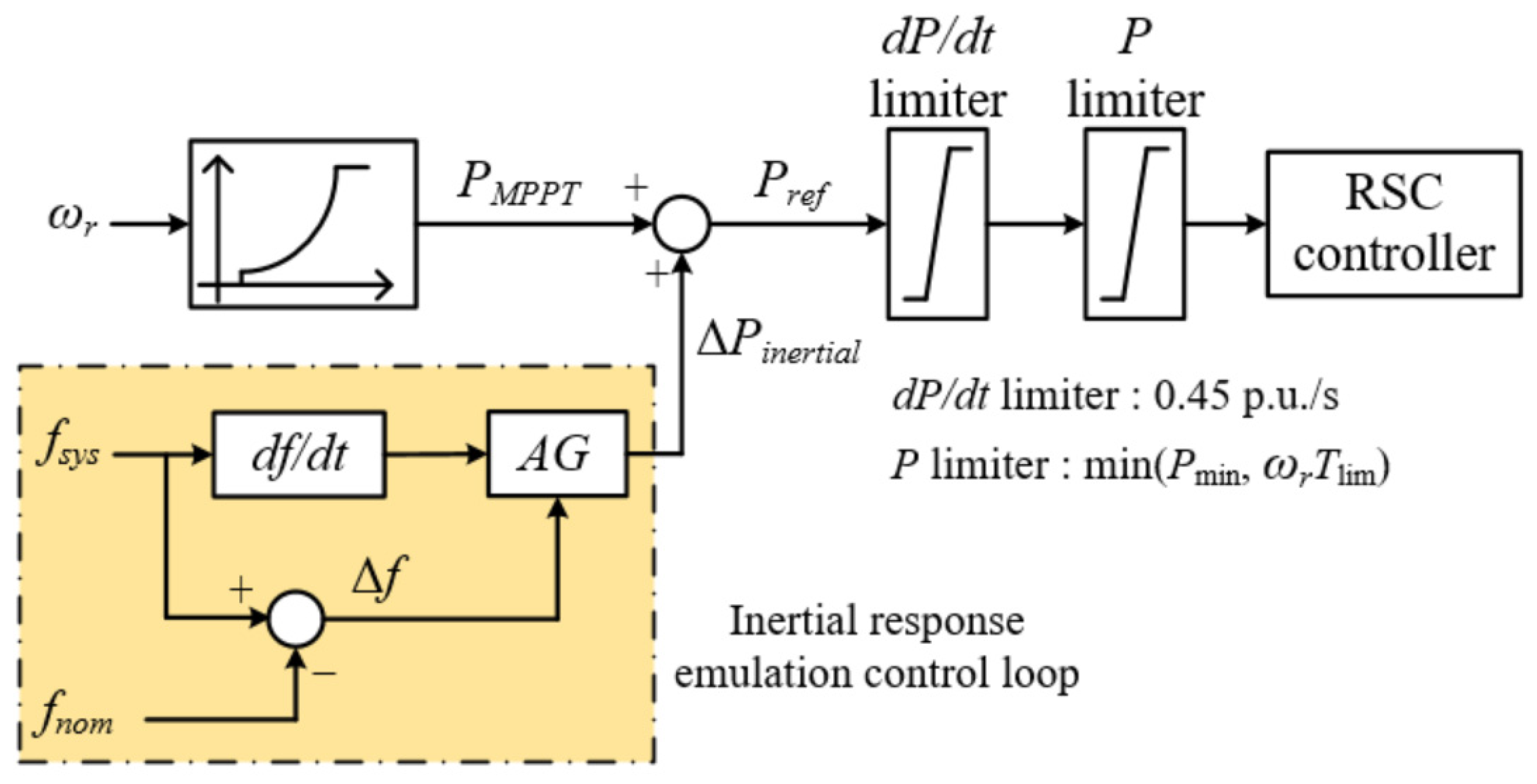
Figure 3 illustrates the control concept of the inertial response emulated control scheme of the DFIG. Once the system frequency exceeds the deadband, the control mode of the DFIG switches from the MPPT control mode to inertial response emulated control mode. The active power reference for the inertial response emulated control scheme (
Pref), which consists of the reference for the MPPT operation (top control loop, which is a cube function of the rotor speed) and the output of inertial response emulated control loop (bottom control loop, which is calculated by control coefficient and
df/dt). Hence, the benefit of boosting the inertial response capability of the DFIG critically depends on the control coefficient.
where
PMPPT is the output of MPPT operation. Δ
Pinertial is the output of the inertial response emulated control loop.
AG is the control coefficient.
As in [
18], the control coefficient of the traditional inertial response emulated control scheme is unchanged, while the rotor kinetic energy of the DFIG is different so that the benefits of improving the maximum system frequency deviation and
df/dt are restricted while the rotating kinetic energy utilized is insufficient (even though the DFIG has adequate rotating kinetic energies). In addition, the inertial response emulated control scheme is dominated during the beginning stage of the disturbance and provides less of a benefit for improving the maximum frequency deviation due to the decreasing
df/dt. This research suggests an adaptive inertial response emulated control scheme of a DFIG to further reduce the maximum system frequency deviation and
df/dt effectively for various disturbances. To this end, the control coefficient is coupled with the system frequency deviation so as to regulate the control coefficient according to the system frequency deviation, as represented in:
where
k1 is the inertia time constant control factor and is able to regulate the benefit of improving the inertial response capability of the DFIG.
k2 is the order of the power function of the frequency deviation to achieve various increasing rate of the control coefficient.
As shown in
Figure 3, to implement the proposed scheme, an additional control loop is employed. The input signals are frequency deviation and
df/dt. The former is used to calculate the various inertial constant; the latter focuses on calculating the additional power with the derived various inertial constant.
Figure 4 illustrates the comparisons of the emulated inertia constant and control coefficients of the proposed scheme when
k2 = 1,
k2 = 2, and
k2 = 3. It is clearly indicated that the emulated inertial time and control coefficient decrease with an increasing of the
k2 due to the fact that the frequency deviation is smaller than one. In addition, the increasing rate of the emulated inertial time and control coefficient in the case of
k2 = 1 is more than in the other cases. Thus, the incremental power for the proposed scheme is generated from the DFIG to improve the inertia response capability.
Figure 5 displays the comparisons of the emulated inertia constant and control coefficients of the proposed (
k2 = 1) and conventional inertial response emulated control schemes. The control gain of the conventional scheme is irrespective of the disturbance sizes (various frequency deviations). This is the reason that the benefit of improving inertial response capability is limited. The emulated inertia constant and control coefficient of the proposed inertial response emulated control scheme is a function of the frequency deviation (see (10)), which increases with the frequency deviation. In addition, the difference of them between both inertial response emulated control schemes becomes large so as to inject more power to the power grid to compensate for the power imbalance. As a result, the proposed inertial response emulated scheme is adaptive to various disturbances (various frequency deviations).
5. Model System
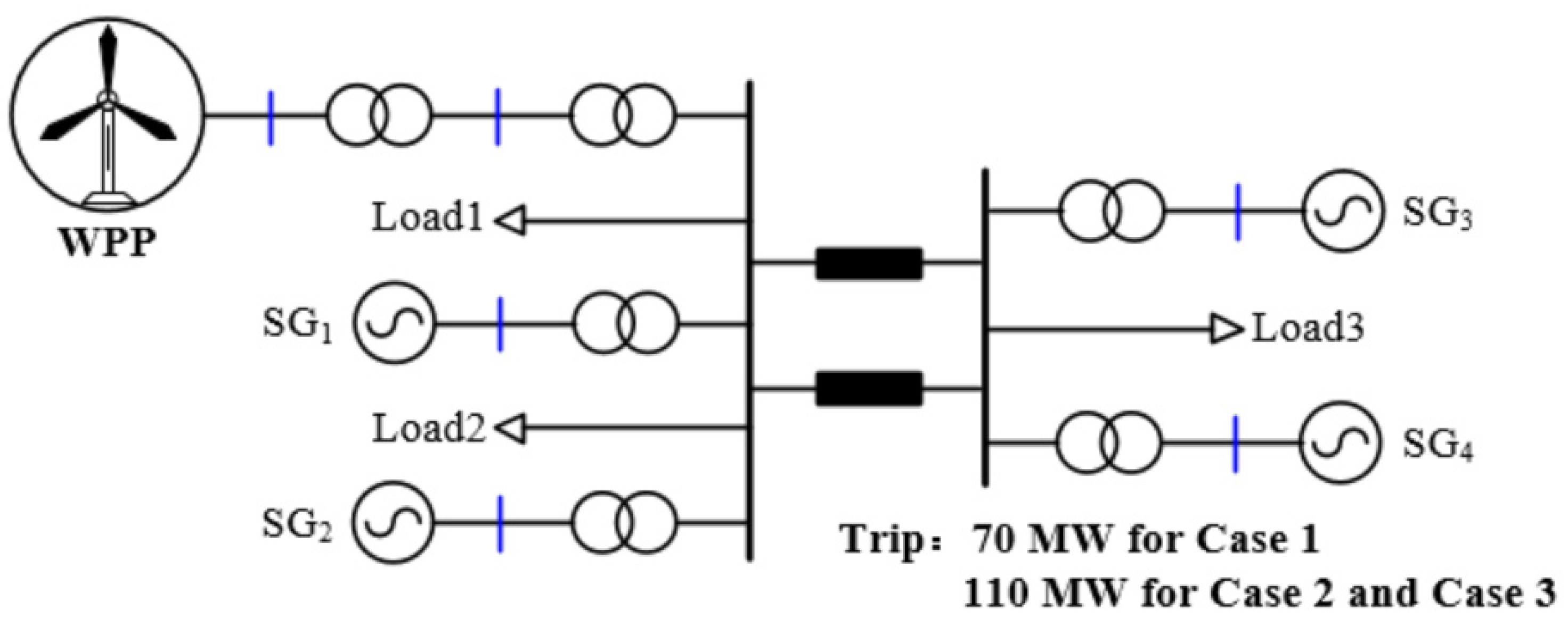
To verify the efficacy of the proposed inertial response emulated control scheme, three cases with various sizes of disturbance and wind speed conditions are carried out using the model system illustrated in
Figure 6. The model system comprises an aggregated DFIG-based wind farm, four traditional synchronous generators, and static load. As disturbances, SG
4 is tripped out from the power grid at 40 s.
To model an electric power system that has a low ramping capacity, each of the traditional synchronous generators is equipped with IEEEG1 steam governor model and IEEE X1 exciter model. The control coefficient and deadband for the primary frequency response are set to 5% and 0.033 Hz, respectively. No secondary frequency response is included in the traditional synchronous generators. The inertia time constants for 100 MVA-SGs and 200 MVA-SGs are 4.0 s and 4.3 s, respectively [
26].
The performance of the proposed inertial response emulated control scheme with various disturbances (80 MW for Case 1, 120 MW for Cases 2 and 3) and wind speed conditions (fixed wind speed conditions for Cases 1 and 2, Random wind speed conditions for Case 3) is investigated. The performance of the proposed adaptive inertial response emulated control scheme (
k2 = 1) is compared to that of MPPT operation and the inertial response emulated control scheme with unchanged control coefficient (conventional scheme), as in [
13].
Figure 7,
Figure 8 and
Figure 9 display the comparison results for all cases.
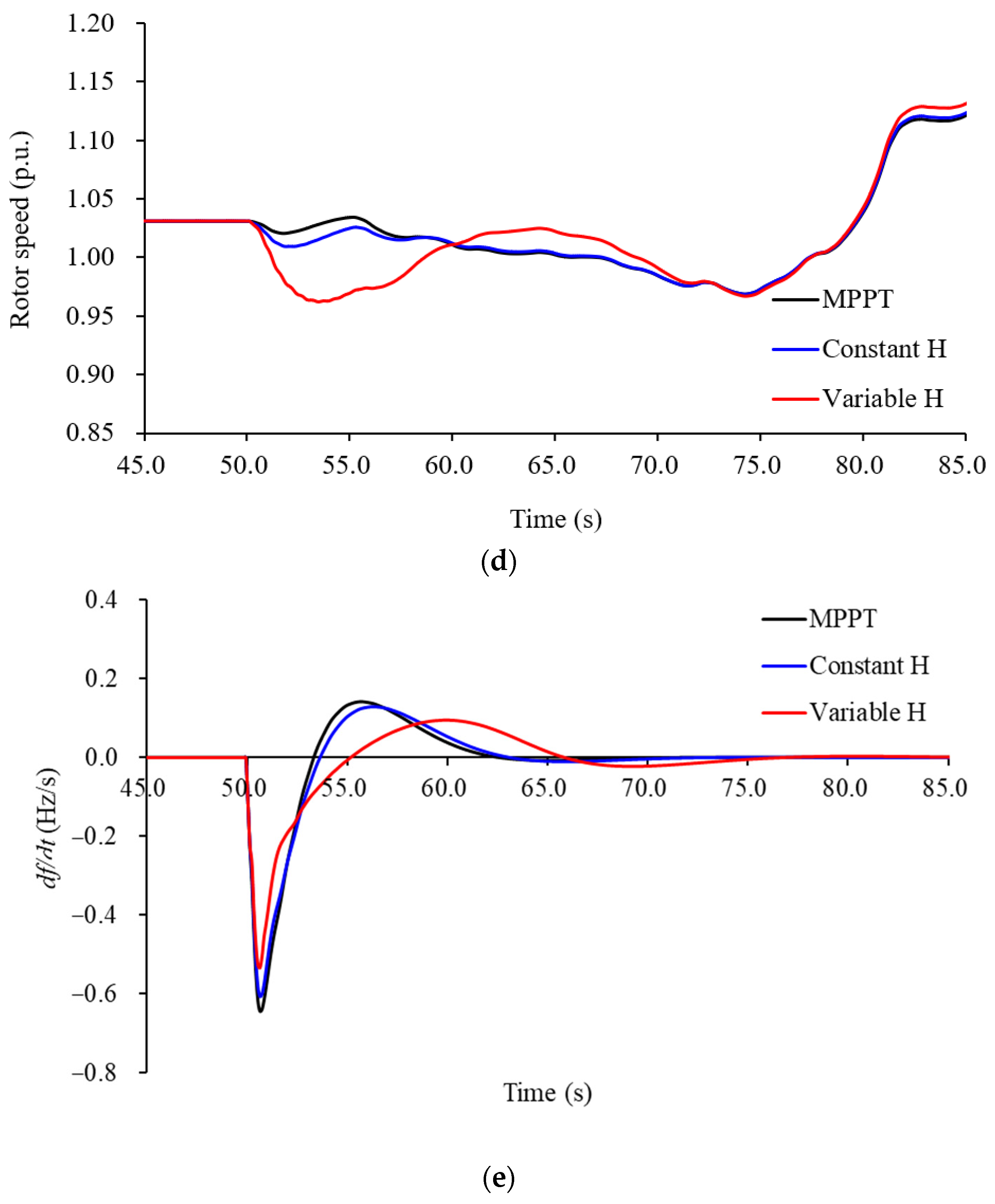
5.1. Case1: Wind Speed of 9.0 m/s, Disturbance of 70 MW
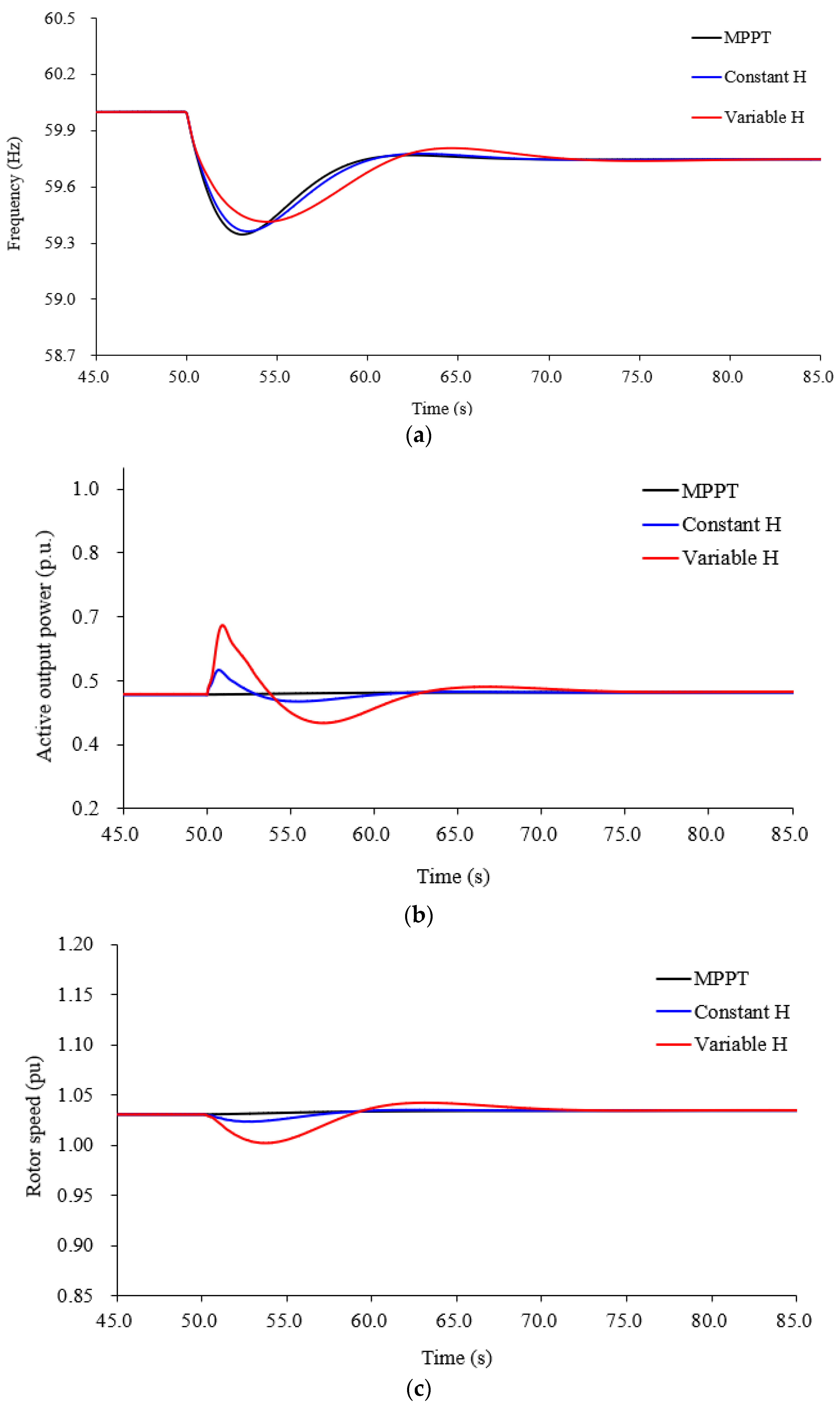
In the conventional inertial response emulated control scheme, the frequency nadir and maximum
df/dt are 59.364 Hz and −0.377 Hz/s, respectively, which are more than those of the MPPT operation by 0.017 Hz and −0.095 Hz/s, respectively (see
Figure 7a,e). The reason is that the conventional inertial response emulated control scheme with the unchanged inertia constant can provide a certain amount of active power to the gird (see
Figure 7b). In the proposed adaptive inertial response emulated control scheme, the frequency nadir and maximum
df/dt are 59.415 Hz and −0.338 Hz/s, respectively (see
Figure 7a,e). They are better than those of the conventional inertial response emulated control scheme by 0.051 Hz and 0.039 Hz/s, respectively, since more active power is injected to the grid before the frequency nadir due to the variable inertia constant proposed in (10), as shown in
Figure 7a,b.
As shown in
Figure 7b,d, due to the control coefficient of the proposed inertial response emulated control scheme, which is coupled with the frequency deviation, the auxiliary active power is more than that of the conventional inertial response emulated control scheme well as the output power. This is the reason that the inertial response capability of the proposed inertial response emulated control scheme is better than conventional inertial response emulated control scheme.
5.2. Case 2: Wind Speed of 9.0 m/s, Disturbance of 110 MW
In this case, a severe disturbance is employed to investigate the benefit of the proposed inertial response emulated control scheme.
In the proposed adaptive inertial response emulated control scheme, the frequency nadir and maximum
df/dt are 59.080 Hz and −0.532 Hz/s, respectively (see
Figure 8a,e). They are better than those of the conventional inertial response emulated control scheme by 0.113 Hz and −0.073 Hz/s, respectively since more active power is injected to the grid before the frequency nadir due to the variable inertia constant proposed in (10), as shown in
Figure 8b.
In addition, due to the severe disturbance, the maximum frequency deviation and maximum
df/dt for all control schemes are less than those of Case 1. The improvements of the maximum frequency deviation and maximum
df/dt of the proposed inertial response emulated control scheme are better than Case 1. This is due to more active power injection from the DFIG caused by the increasing
df/dt. As shown in
Figure 7c and
Figure 8c, since the large control coefficient is calculated and the frequency deviation is increasing, the reduction of this case is more than that of Case 1.
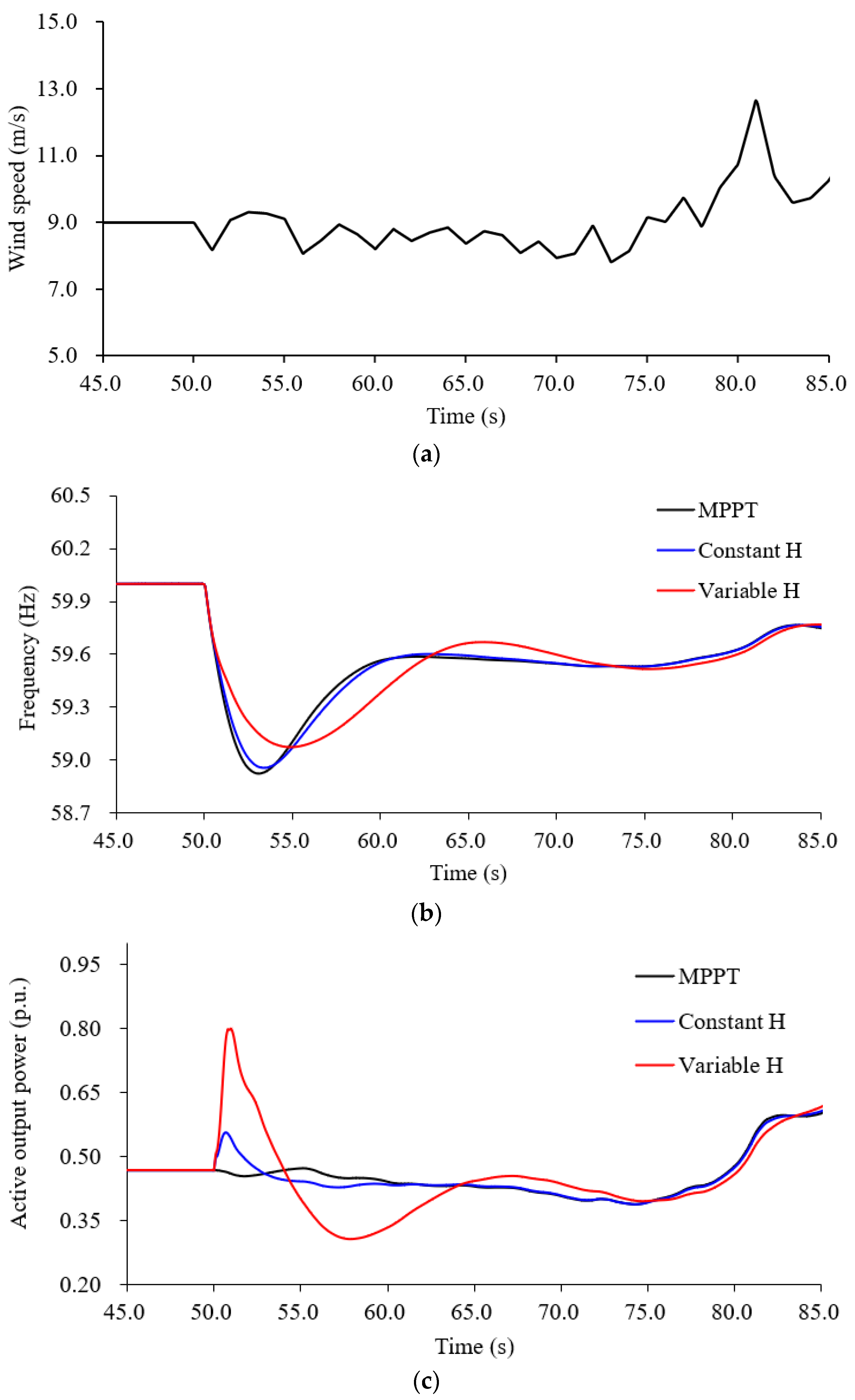
5.3. Case 3: Random Wind Condition, Disturbance of 110 MW
To investigate the benefit of the proposed inertial response emulated scheme with a random wind speed condition, the random wind condition is employed (see
Figure 9a) while the disturbance is same as Case 2. In the proposed adaptive inertial response emulated control scheme, the frequency nadir and maximum
df/dt are 59.074 Hz and −0.533 Hz/s, respectively (see
Figure 9b,e). They are better than those of the conventional inertial response emulated control scheme by 0.119 Hz and 0.074 Hz/s, respectively, due to the more power injection (see
Figure 9b,c).
In addition, due to random wind speed conditions, the maximum frequency deviation and maximum
df/dt for all control schemes are slightly less than those of Case 2. This is due to slightly decreasing wind speed, as shown in
Figure 9a.
Table 1 shows the comparison indices including frequency nadirs and maximum ROCOFs for all cases.
Simulation results of above three cases clearly indicate that the proposed inertial response emulated control scheme can reduce the maximum df/dt and heighten the frequency nadir effectively under various disturbances and wind speed conditions. As the increasing sizes of disturbance, the df/dt and frequency deviation become large so that the contribution for improving the inertial response capability. Thus, the proposed inertial response emulated control scheme is adaptive to the sizes of disturbance.
6. Conclusions
In this paper, an adaptive inertial response emulated control strategy is proposed to improve the maximum frequency deviation and df/dt. To address this, the control coefficient is coupled with the system frequency deviation so as to regulate the control coefficient according to the variation of the system frequency deviation. The performances of the proposed inertial response emulated control strategy were verified with various sizes of disturbance and wind speed conditions using EMTP-RV, and the contributions of this strategy are as follows:
- (1)
The proposed inertia constant is coupled with the system frequency deviation. Thus, the proposed inertia control scheme can provide various inertial response capability during disturbance according to the frequency deviation.
- (2)
Under different disturbances, the DFIG implemented with proposed scheme can generate more power to support the system to improve the inertial response capability.
Simulation results clearly indicate that the proposed inertial response emulated strategy shows better performances, especially in a serve frequency event and random wind speed conditions.


