Abstract
Concentrating photovoltaic-thermal (CPVT) collectors have to face the challenge of contrary temperature requirements in the single receiver parts. The PV cells require low temperatures to achieve high efficiency, whereas the thermal part should generate high temperatures for providing industrial heat. The approach of “Spectral Splitting” can offer a solution for compact CPVT receivers; however, a clear quantification of the expected conversion efficiency is difficult. Therefore, this paper describes a modelling methodology for obtaining electrical and thermal performance parameters for a Spectral Splitting configuration using semiconductor-doped glass combined with appropriate heat transfer fluid. The PV technologies c-Si, CIGS and CdTe are considered. The presented model yields distinct results for maximising the electrical efficiency, calculates the reduction in waste heat dissipation within the cells and assesses the impacts of concentration factor and cell temperature. An optimised configuration could be found with CIGS cells, impinged by a selected wavelength spectrum between 868 nm and 1100 nm, where the theoretical efficiency reaches 42.9%. The waste heat dissipation within the cells is reduced by 84.9%, compared to a full-spectrum operation. The depicted CPVT receiver design using bendable thin-film PV cells will be realised as a prototype in a subsequent project phase.
1. Introduction
In the year 2015, half of the overall final energy consumption in the EU28 was required for heating and cooling purposes. Industrial heating processes caused 32% of this demand, whereby more than two-thirds of this energy amount was delivered at temperature levels above 100 °C [1]. However, the contribution of renewable heat sources for satisfying this medium and high-temperature heat demand in the industrial sector is minor, as only 3% of the worldwide installed solar thermal collector capacity in 2019 is applied to process heat, solar cooling or district heating [2]. One reason for this situation might be that available conventional collector technologies can generate temperatures above 100 °C only with reduced efficiency [3,4]. Therefore, if the industrial sector shall be supported with emission-free heat in future energy supply systems, efficient and economic mid-temperature solar thermal collectors are substantially required.
Furthermore, besides this described industrial heat demand, there is the need for future energy sources to be maximum flexible in order to be able to react to fluctuating energy flows. The simultaneous generation of industrial heat and electricity in one solar system can provide a possible solution. Although, such mid-temperature hybrid collectors mostly have to face one serious structural disadvantage if they are completed as a compact component. The electrical part of the solar conversion system should be kept at low temperatures to work most efficiently, whereas the thermal part should provide temperatures as high as possible in order to be applicable to industrial heat sinks. Implementing both parts in one system without any further measures leads to an undesired heat transfer and, therefore, to a reduction in both the electrical and thermal performance. Improvement of this discrepancy in compact concentrating PVT (CPVT) systems could be achieved on the one hand by implementing effective thermal decoupling between the electrical and the thermal receiver part. On the other hand, the approach of “Spectral Splitting” was investigated in various research activities and appeared as an appropriate method to raise the performance of CPVT collectors [5,6,7].
The concept of Spectral Splitting has the main purpose of increasing the conversion efficiency of PV cells in a CPVT receiver. This is performed by splitting the incident solar radiation into specific ranges of wavelengths that are converted into energy either in the thermal or in the electrical part of the receiver. As the PV cells only receive wavelengths in the region of high spectral response, the absorbed solar energy can be converted into electricity with maximum efficiency. Moreover, the cells are not being heated up additionally by the relaxation of electrons that were generated by high-energetic photons at short wavelengths or by the dissipation of incident photons with energy levels below the bandgap energy. This avoidance of temperature increase contributes to an improved conversion performance of the solar cells [8].
Figure 1 illustrates the separation of wavelengths, as it could be suitable for crystalline Silicon cells (c-Si). Only the spectral range between 700 nm and 1100 nm (shown in blue) is provided to the PV cells, where the spectral response of c-Si reaches its maximum. The remaining parts of the solar spectrum (280 nm to 700 nm and beyond 1100 nm, shown in red) are directly converted into heat within the thermal part of the receiver and do not reach the PV cells.
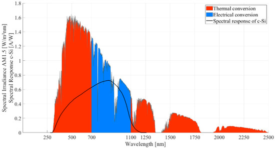
Figure 1.
Separation of the solar spectrum AM1.5 in the concept of Spectral Splitting.
Comprehensive reviews of the different spectrum splitting technologies have been presented in the last two decades [7,9,10,11], describing various concepts based on interference filters, selective mirrors, glass prisms and others. Each approach has its specific benefits and challenges and a particular grade of complexity in construction, which is directly linked to the resulting costs of such a system. If a CPVT collector including Spectral Splitting should become competitive to a separated solar thermal and photovoltaic energy conversion system, the design and construction need to be kept as simple as possible. For a similar reason, Mojiri et al. [9] concluded their review with the recommendation to extend research in compact CPVT receivers using the Spectral Splitting method of selective absorption, either by liquid or solid filtering or by a combination of both.
In Spectral Splitting receiver concepts with liquid absorption filters, the separation of wavelength ranges must take place within the heat transfer fluid (HTF). Thus, the fluid itself is required to provide adjustable spectral properties. Such a Spectral Splitting receiver concept was developed by Crisostomo et al. [12], where the key component is the nanofluid liquid filter with water as the base fluid and suspended silver nanoparticles. Four different concentrations of these Ag–SiO2 particles between 0.6 and 2.5 × 10⁻² wt% were used to adjust the spectral absorptivity. The hybrid receiver could generate 9% more energy output than the PV-only version under the same conditions with a maximum thermal output temperature of 70 °C. Han et al. [13] investigated a hybrid base fluid consisting of cobalt sulphate (CoSO4) and propylene glycol (PG). Suspended silver nanoparticles in different concentrations were applied to adjust the spectral absorption characteristic of the nanofluid. A maximum temperature of 61.7 °C was achieved in the stagnant fluid during the performance measurements. The thermal efficiency was calculated at a maximum fluid temperature of 35 °C, reaching 79.4% with the highest concentration of silver particles. Otanicar et al. [14] developed a CPVT receiver for utilising a filtering fluid that combines silicone oil with gold and indium tin oxide nanoparticles and experimentally achieved an electrical efficiency of 4% and a thermal efficiency of 61% at an outlet temperature of 110 °C. Huaxu et al. [15] investigated the efficiency of a CPVT system depending on the concentration of ZnO nanoparticles added to glycol as heat transfer fluid. Huang et al. [16] assumed the availability of optimal filter fluids and modelled the conversion efficiencies with two different PV cell technologies. Vacuum gaps surrounding the rectangular filter fluid channel reduce the thermal losses to ambient, leading to possible outlet temperatures of 412 °C.
Heat transfer fluids without nanoparticles were investigated by Looser et al. [17], mainly with the aim to analyse the long-term performance of candidate fluids by accelerated stress tests. The most suitable HTF among the 18 candidates was an industrial-grade Propylene Glycol (PG). It has a crystal clear appearance, was not harmed by the performed long-term stress tests and is inexpensive. In terms of spectral properties, PG acts as a short-pass filter, as it provides the desired decrease in transmittance for wavelengths beyond 1100 nm [17,18], leading to direct absorption of this spectrum range that is not suitable for the electrical energy conversion (see Figure 1, the red area from 1100 nm upwards). However, the lower wavelength threshold for limiting the transmitted irradiance to the PV cells (blue area in Figure 1) cannot be supplied by the fluid, as its transmittance is more than 90% over the entire visual spectrum range. Therefore, solid absorption filters made of semiconductor-doped glass (SDG) can be combined with heat transfer fluids in order to establish the required band-pass filtering.
Such a combined Spectral Splitting concept for a compact hybrid receiver was investigated by Stanley et al. [19]. The thermal receiver part consists of a circular glass tube hosting the absorption filter. The electrical receiver part is made of an aluminium extrusion profile carrying the PV cells. A cooling channel on the backside of the PV carrier provides a heat sink for the remaining waste heat in the cells. Experimental measurements obtained a thermal efficiency of the receiver prototype of 31% at 120 °C outlet temperature and electrical efficiency of approx. 3.8%. Working on the same concept, Mojiri et al. [20] modelled the electrical efficiency for various filter combinations, using PG as heat transfer fluid and different SDG filters. The electrical conversion efficiency related to the irradiance reaching the PV cells could be increased from 20.7% (reference value without filtering) to 26.8%. A different approach for designing a hybrid receiver was chosen by Hangweirer et al. [21]. The principle construction is similar to the one of Stanley et al., but the fluid channels had a rectangular cross section. The thermal decoupling between the thermal receiver and the PV cells is performed by implementing an air gap. Alternatively, filling the gap with highly transparent silicone was investigated as well. An analytic calculation for different gap thicknesses and various temperature differences between thermal and electrical receiver parts showed a reduction in the heat flux through the gap by a factor of 4, if air is used instead of silicone (@ K, gap thickness of 10 mm) [22]. Reinbrech et al. [23] enhanced the design of Hangweirer et al. [21]. The main difference is that waste heat from the PV cells is not dissipated to ambient air but absorbed by an additional fluid layer so that it can contribute to the thermal output of the receiver and increase its thermal efficiency. Fourteen types of absorption filters were included in the analysis with characteristic wavelengths between 395 nm and 850 nm. Experimental experience [24] confirms the durability and applicability of these SDG filters for such applications. The most recent research outcomes in this specific area of Spectral Splitting concepts were published by Han et al. [25], who investigated the filtering performance of PG only (without SDG filter) in comparison to the combination of PG and SDG filter. Moreover, the SDG filter was designed in a tubular way, which appears as a novelty in contrast to the planar filter arrangements so far. Due to the chosen filter configuration, the overall electrical and thermal performance of this CPVT system could be increased from 12.73% (PV-only) to 46.77%.
Apart from Spectral Splitting by liquid or solid absorption configurations, Widyolar et al. [26] and Wang et al. [27] compared ideal optical filters with interference filters and solar cell filters. In addition to the performed optimisation of conversion efficiencies, the investigations were enhanced towards economic analyses, which is an important factor if the CPVT system is considered for real applications such as supporting dairy farms [27].
Although the concept of Spectral Splitting seems to be promising, a clear quantification of the possible electrical efficiency increase appears to be challenging, as the presented numbers differ significantly. Several reasons can be identified for this circumstance. On the one hand, there is a disagreement about the irradiance value used to calculate the electrical conversion efficiency of the PV cell. In some cases, the total irradiance on the collector is considered, but in other models, only the irradiance impinging the PV cells is taken as the basis value. On the other hand, there are distinct definitions of different kinds of PV cell efficiency, namely the spectral efficiency, the theoretical efficiency and the real efficiency [28,29,30]; however, the presented models partly do not clearly point out which kind of efficiency is considered. Furthermore, in some papers, there is a shortage of clearness in terms of optimised filter configuration, as the performed optimisation depends on variable weighting factors or does not yield an explicit maximum of any parameter that denotes an optimum. Regarding the proposed receiver designs, it can be observed that experimental feasibility might not have been considered sufficiently in some cases, as, e.g., SDG filters in tubular shape or vacuum gaps with a rectangular cross section are difficult to realise.
Therefore, this paper aims to provide some clarification in terms of quantifying the effect of Spectral Splitting in a CPVT receiver, considering the combination of SDG filters and heat transfer fluids without nanoparticles. The developed modelling approach for obtaining electrical and thermal performance parameters is described in detail and includes the utilisation of the three PV technologies c-Si, CIGS and CdTe. As the spectral efficiency of a PV cell only depends on the received spectrum and on the bandgap of the specific semiconductor [28,29,30], this outcome of the model reveals clearly the potential efficiency increase with varying Spectral Splitting filter configurations, validated by comparison with full spectrum operation. Furthermore, the theoretical efficiency yielded by the model is less idealised and gives a more realistic view of this approach. The performed efficiency calculations are only based on the irradiance impinging the PV cells because this is the most conclusive way to the opinion of the authors to quantify the effect of Spectral Splitting. Clear optimisation results can be provided, where the spectral and the theoretical efficiencies reach maximum values. These optimised filter configurations are used to analyse the impact of cell temperature and concentration factors on the performance parameters. Besides the modelling work, this paper presents a novel CPVT receiver design that was developed with the goal to be implemented as a prototype, including the optimised filter configuration derived by the model. Therefore, feasibility was a major request within the receiver development process and the modelling approach as well. A subsequent paper will cover the assembling of the CPVT receiver prototype and performance measurements on a Fresnel mirror field.
2. Development of a Novel CPVT Receiver Design
Based on the outcomes of the literature survey described above, the further development of a compact CPVT receiver within the present research project is considering the Spectral Splitting approach using an SDG filter in combination with an appropriate HTF. The receiver concept phase yielded two potential designs that are treated further on by an entire modelling approach. One receiver design proposal is developed for the use of c-Si PV cells, whereas the second one includes bendable thin-film PV technology. Details of these newly developed CPVT receiver designs are published in Resch and Höller [31].
The CPVT receiver design proposal using bendable thin-film PV cells is displayed in the following Figure 2 and Figure 3. The inner glass tubes carry the solid absorption filters that are made of semiconductor-doped glass with selectable transmission characteristics. The heat transfer fluid flows through the inner glass tubes, taking the heat absorbed by the filters but also directly absorbing the long wavelengths of the incident solar spectrum. The glass tube envelope is closed by end caps (not displayed) and affords a resting air volume around the inner glass tubes, serving as thermal decoupling to the PV part as well as thermal insulation to ambient air. Thin-film PV cells are bent over the outside of the glass tube envelope. If mounted above a Fresnel mirror field, the concentrated sunlight enters the receiver at the bottom through the glass envelope and impinges the inner glass tubes, where the Spectral Splitting takes place. According to the exemplary filter configuration described in Figure 1, the solid filter absorbs the short wavelengths between 280 nm and 700 nm, whereas the HTF directly absorbs the long-wavelength range beyond 1100 nm. Experimental investigations pointed out that suitable fluids such as water, propylene glycol or thermal oils show a significant decrease in transmissivity in the spectral range above 1100 nm [18], which exactly meets the requirements. The absorbed energy is converted into heat and transferred to an applied heat sink by the HTF. By contrast, the spectral range between 700 nm and 1100 nm is transmitted upwards to the PV cells, where it is efficiently converted into electricity.
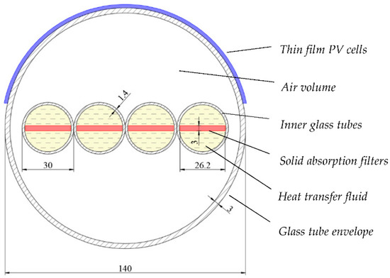
Figure 2.
Cross section of the novel CPVT receiver design with bendable PV cells, solid absorption filters and enveloping glass tube (dimensions given in mm).
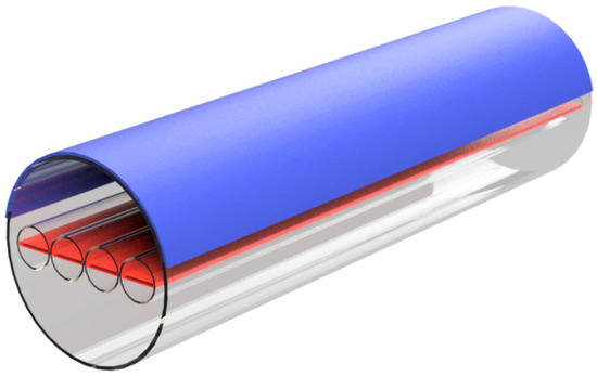
Figure 3.
Rendering of the novel CPVT receiver with bendable PV cells, solid absorption filters and enveloping glass tube.
The presented CPVT receiver design was developed with the main aim to be implemented as a prototype for performing experimental measurements on a Fresnel mirror field. Therefore, material availability was a significant criterion during the design phase. The cross section of the receiver in Figure 2 reveals the exact dimensions of glass tubes and absorption filters that are available on the market. The assembly of a prototype with a length of 1.5 m, according to Figure 3, is already completed. Details of the prototype assembling and experimental performance measurements will be provided in a subsequent paper.
3. Modelling the Potential Gain of Conversion Performance
The potential gain of electrical conversion performance, the waste heat dissipation within the PV cells and the thermal power output of the receiver were modelled in MATLABTM for the considered compact CPVT receiver designs [31]. The analysis was conducted for the three PV cell technologies, c-Si, CIGS and CdTe. The following key parameters were calculated:
- Spectral efficiency of the PV cells in %;
- Theoretical efficiency of the PV cells in %;
- Maximum electrical power output considering spectral efficiency in Wel/m2;
- Electrical power output in idealised MPP operation in Wel/m2;
- Waste heat dissipated in the PV cells in Wth/m2;
- Idealised thermal power output of the receiver in Wth/m2.
3.1. Modelling Methodology
The modelling of the Spectral Splitting concept was performed in two stages. Firstly, the lower threshold wavelength of the solid filter was increased iteratively from 300 nm to 1100 nm in order to find the maximum electrical conversion efficiency. Secondly, this optimised filter configuration was used to calculate the impacts of the cell temperature and the concentration ratio on the conversion performance.
All calculations were performed in an area-related way. Hence, current values are expressed in A/m2, and electrical, thermal and radiant power values are given in W/m2.
3.1.1. Optimisation of Electrical Conversion Efficiency
In a first step, an idealised configuration is considered, i.e., all optical, thermal or electrical losses are neglected. The photocurrent of a PV cell can be calculated by the spectral response and the solar irradiance [28]:
The spectral response is further expressed as a function of the external quantum efficiency , in combination with the elementary charge , the Planck constant and the speed of light [28]:
The generated total photocurrent results in:
If the full solar spectrum is applied to the PV cells, the wavelength limits and are defined by the minimum and maximum wavelengths of the solar spectrum data, which are 280 nm and 4000 nm for the case of the considered AM1.5 spectrum. If the generated photocurrent in the described Spectral Splitting arrangement is calculated, corresponds to the lower threshold wavelength given by the absorption filter, whereas is defined by the upper threshold wavelength of 1100 nm due to the spectral behaviour of the HTF.
The idealised photovoltage of a PV cell is related to the bandgap energy [29]:
The spectral efficiency of an ideal PV cell can be calculated as the ratio between the generated electrical power and the solar irradiance [29]:
It is important to emphasize for the Spectral Splitting configuration that in W/m2 is the solar radiant flux density entering the PV cells, which is different from the total solar irradiance impinging the entire receiver. depends on the particular chosen absorption filter and the resulting lower threshold wavelength :
The thermal power dissipated within the PV cells is considered as waste heat. It is calculated by the difference between the solar irradiance and the generated electrical power :
The thermal power output of the receiver is generated within the absorption filter and the heat transfer fluid by converting the absorbed wavelength ranges into heat. In an idealised configuration without considering any optical or thermal losses, the generated thermal power output is:
The described idealised analysis of energy conversion in PV cells with Spectral Splitting provides a first insight into the expected impacts on efficiencies and powers. Nevertheless, real operating conditions in PV cells differ significantly from the ideal state. One further important key parameter for quantifying the energy conversion in PV technologies is the theoretical efficiency . Compared to the spectral efficiency , the theoretical efficiency includes the fact that the open-circuit voltage in a real PV cell is smaller than the photovoltage . Furthermore, the fill factor is considered by , as it also has a distinct influence on the conversion performance [29].
The maximum possible open-circuit voltage is given by the following equation [29]:
The short-circuit current is equal to the photocurrent . The constant is defined by 40,000 A/cm2 [29]. The thermal diode voltage is calculated as follows [29]:
where is the diode quality factor, is the Boltzmann constant and is the absolute temperature of the considered PV cell.
The idealised fill factor is obtained by using this empirical equation [29]:
On the other hand, the fill factor also describes the relationship between the electrical output power in the idealised maximum power point (MPP) and the product of and [29]:
Therefore, the expected electrical power output is:
The theoretical efficiency is given by [29]:
The thermal power dissipated within the PV cells is calculated as follows:
The thermal output of the entire receiver is again considered in an idealised way without calculating any losses to ambient. Following Equation (8), the thermal output power is:
3.1.2. Impacts of Cell Temperature and Concentration Factor
In the second stage, the impacts of the cell temperature and the concentration factor are analysed for the consideration of theoretical efficiency. The optimised filter configuration provided by the first stage is the basis for the following calculations. The temperature of the PV cell is varied between 25 °C and 100 °C, and the concentration factor is assumed to range from 1 to 50 suns.
The electrical power output of the PV cell decreases with the cell temperature according to the temperature coefficient [28]:
In Equation (17), is the idealised output power at 25 °C. Similar to Equation (7), the thermal power dissipated within the PV cells is:
The temperature-dependent theoretical conversion efficiency is calculated as follows:
The idealised thermal output of the entire receiver does not change with the PV cell temperature, as thermal losses are not considered at this stage of the modelling. Nevertheless, this value can serve as an indication of the thermal potential of the Spectral Splitting configuration.
The concentration factor influences the photocurrent , the open-circuit voltage and the fill factor [30] in the following ways. The photocurrent changes linearly with the concentration factor, referring to the photocurrent at the standard irradiance of one sun:
The open-circuit voltage shows a logarithmic dependency on the concentration factor, whereby is the corresponding open-circuit voltage at one sun:
Subsequently, the fill factor can be calculated in dependence of the concentration factor, similarly to Equation (11):
The electrical power output at different concentration factors is:
The theoretical efficiency is calculated as follows:
The thermal power dissipated in the PV cells , depending on , is:
Again, the entire thermal output of the receiver is calculated in an idealised way, as no losses are considered. Therefore, rises linearly with the concentration factor .
3.2. Data Base for Modelling
The modelling is based on the AM1.5 spectrum ASTM G-173-03 from NREL [32], considering the global irradiance on a 37° tilted surface, with a total irradiance value of 1000.4 W/m2. Although a concentrating collector can only convert the direct portion of the irradiance, it appears to be more meaningful for the aimed comparison between the Spectral Splitting approach and the conventional full spectrum operation of the PV cells to use an equal basis of irradiance.
The required data of the PV cells were taken from the following types of cells, representing the current state of the art for the three technologies c-Si, CIGS and CdTe. The c-Si cell is a p-type interdigitated back contact (IBC) cell manufactured by the Institute for Solar Energy Research, Hameln (ISFH). The real cell efficiency of 26.1% was measured in February 2018 by ISFH [33]. The bandgap energy is 1.12 eV and the temperature coefficient is −0.45%/K [29]. The CIGS technology is represented by a Cu(In,Ga)(Se,S)2 cell, manufactured by Solar Frontier. The real cell efficiency of 22.9% was measured in November 2017 by the Japanese National Institute of Advanced Industrial Science and Technology (AIST). The bandgap energy is 1.13 eV [33,34] and the temperature coefficient is −0.31%/K [35]. The analysed CdTe cell is manufactured by First Solar. The real cell efficiency of 21.0% was measured in August 2014 by Newport [36]. The bandgap energy is 1.5 eV [30] and the temperature coefficient is −0.32%/K [37].
The external quantum efficiency for each cell type was taken from measurement results [33,36]. Using Equation (2), the spectral response was calculated for the three considered PV cells. Figure 4 depicts the spectral irradiance of the applied AM1.5 spectrum and the spectral responses used as the basis for the subsequent analysis.
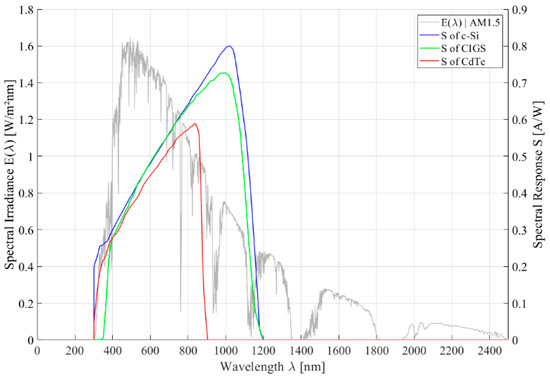
Figure 4.
AM1.5 spectrum and spectral response S of the considered c-Si, CIGS and CdTe PV cells.
4. Modelling Results of Optimised Electrical Conversion Efficiency
This chapter summarizes the results of optimising the electrical conversion efficiency by changing the lower threshold wavelength of the solid absorption filter, separately for each of the considered PV technologies. The concentration factor is defined at one sun, and the cell temperature is 25 °C for all the calculations in this chapter.
4.1. Optimised Electrical Conversion Efficiency for c-Si Cells
The performed optimisation of the Spectral Splitting configuration by iteratively changing the lower threshold wavelength of the absorption filter yields the following results for c-Si PV technology, as depicted in Figure 5. Considering the spectral efficiency (left side of Figure 5), the optimum of can be found at 945 nm, where reaches a maximum of 84.4%. The generated electrical power is 81.2 Wel/m2, the idealised thermal power output of the receiver is 904.1 Wth/m2, and the waste heat dissipated within the PV cells is 15.1 Wth/m2. Taking into account the fill factor and the reduced open-circuit voltage of the PV cell, the theoretical efficiency of the electrical conversion is calculated (right part of Figure 5). In this case, the optimum is 902 nm, where shows a maximum of 46.4%. The electrical power output in this consideration is 55.7 Wel/m2, the idealised thermal power output of the receiver is 880.2 Wth/m2, and the waste heat dissipated within the PV cells is 64.5 Wth/m2.
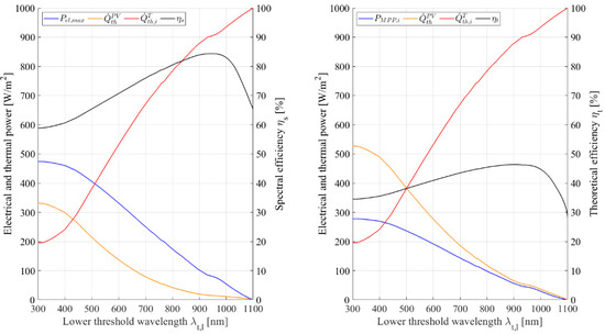
Figure 5.
Key parameters of Spectral Splitting depending on lower threshold wavelength, considering spectral efficiency (left) and theoretical efficiency (right), for c-Si PV technology.
A comparison of these results in Spectral Splitting configuration with the conventional full spectrum exposure of the PV cells is provided in Table 1. Therein, data for full spectrum mode are given on the one hand based on the literature [28], and on the other hand, the full spectrum operation is modelled according to the methodology mentioned above in order to verify the chosen modelling approach. The optimised Spectral Splitting configuration shows an improvement of the theoretical conversion efficiency of 64% compared to the modelled full spectrum operation. The waste heat dissipated within the cells can be reduced by 91%, but the electrical power output also decreases by 80.3%. However, significant additional thermal power can be generated.

Table 1.
Comparison of key parameters at full spectrum and at optimum Spectral Splitting configuration for c-Si PV technology.
4.2. Optimised Electrical Conversion Efficiency for CIGS Cells
For the considered CIGS cell technology, Figure 6 illustrates the results of the efficiency optimisation due to Spectral Splitting. In terms of the spectral efficiency (left side of Figure 6), the maximum of can be found with 76.3% at a lower threshold wavelength of 868 nm. The generated electrical power is 114.6 Wel/m2, the idealised thermal power output of the receiver is 850.2 Wth/m2 and the waste heat dissipated within the PV cells is 35.6 Wth/m2. By contrast, the theoretical efficiency reaches a maximum of 42.9%, if is 823 nm (right part of Figure 6). The electrical output is 82.9 Wel/m2, the idealised thermal power output of the receiver is 807.1 Wth/m2, and the waste heat dissipated within the PV cells is 110.4 Wth/m2.
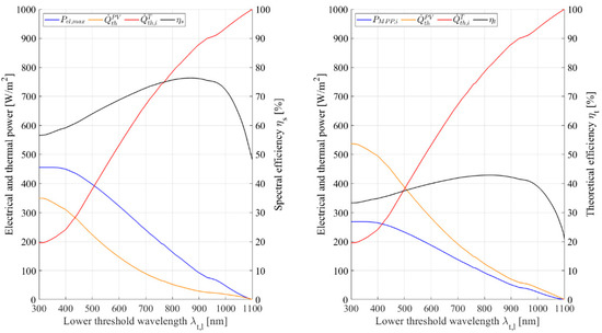
Figure 6.
Key parameters of Spectral Splitting depending on lower threshold wavelength, considering spectral efficiency (left) and theoretical efficiency (right), for CIGS PV technology.
Table 2 provides the comparison between full-spectrum operation and optimised Spectral Splitting configuration for the considered CIGS cells, separately for the spectral efficiency and the theoretical efficiency. Due to Spectral Splitting, can be enhanced by 58.3%, leading to a reduction in the unfavourable waste heat dissipation within the cells by 84.9%. The electrical power output is lowered by 69.4%, but supplementary thermal power output can be gained.
Table 2.
Comparison of key parameters at full spectrum and at optimum Spectral Splitting configuration for CIGS PV technology.
4.3. Optimised Electrical Conversion Efficiency for CdTe Cells
In the case of applying CdTe PV cell technology for the optimisation of the Spectral Splitting configuration, the resulting key parameters depending on the lower threshold wavelength can be seen in Figure 7. By considering the spectral efficiency as a basis for the analysis (left part of Figure 7), the optimum is achieved, if is 515 nm, where is 56.5%. The electrical power is 336.9 Wel/m2 in this configuration, the idealised thermal power output of the receiver is 403.6 Wth/m2, and the waste heat dissipated within the PV cells is 259.9 Wth/m2. The right part of Figure 7 depicts the results considering the theoretical efficiency , which reaches a maximum of 38%, if is 501 nm. is 235.1 Wel/m2 in this configuration, whereas the idealised thermal power output of the receiver is 382 Wth/m2. The waste heat dissipation within the PV cells is 383.3 Wth/m2.
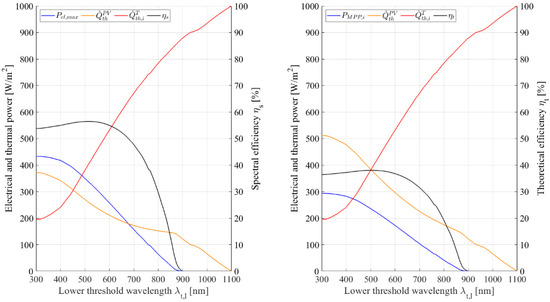
Figure 7.
Key parameters of Spectral Splitting depending on lower threshold wavelength, considering spectral efficiency (left) and theoretical efficiency (right) for CdTe PV technology.
Compared to full-spectrum operation, the relative changes in key parameters can be summarized as follows, based on the absolute values given in Table 3. The theoretical conversion efficiency of the CdTe cells is improved by 29.7% if optimised Spectral Splitting is applied. The electrical power output is reduced by 19.8%, but the waste heat dissipation within the cells also decreases by 45.8%. Additionally, the thermal output power of 382 Wth/m2 can be generated.
Table 3.
Comparison of key parameters at full spectrum and at optimum Spectral Splitting configuration for CdTe PV technology.
5. Results for Modelling the Impact of Cell Temperature and Concentration Factor
This chapter summarizes the modelling results for analysing the impacts of cell temperature and concentration factor on the conversion performance of the three PV technologies c-Si, CIGS and CdTe. The Spectral Splitting configuration with optimised filter wavelength and maximum as calculated in Section 4 was chosen as a basis for this analysis.
5.1. Impact of the Cell Temperature
The impact of the cell temperature on the key performance parameters , and is visualised in Figure 8, separately for the three PV technologies c-Si, CIGS and CdTe. The negative temperature coefficient of all technologies leads to the expected decrease in with the rising temperature. By considering the maximum temperature of 100 °C, the electrical output of c-Si cells is reduced to 36.9 Wel/m2. However, due to the conversion efficiency of 30.7%, the heat dissipation within the cells is 83.3 Wth/m2, which is a significant reduction compared to the heat dissipation of 813 Wth/m2 at full spectrum. In contrast, the results of the CdTe cell analysis look quite different. The negative temperature coefficient of CdTe is 28.9% smaller than the one of c-Si, and therefore the temperature-dependent reduction in the electrical power output is less. Furthermore, the optimised filter configuration of CdTe leads to higher electrical power output than with c-Si or CIGS cells, but the waste heat dissipation within the cells is also significantly higher. If the CdTe cells are at 100 °C, is 28.9%, is 178.7 Wel/m2 and is 439.7 Wth/m2. CIGS cells in the optimised Spectral Splitting configuration show the highest efficiency at 100 °C among the three cell types, where is 32.9%, is 63.6 Wel/m2 and is 129.7 Wth/m2.
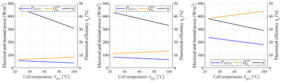
Figure 8.
Key parameters of Spectral Splitting depending on cell temperature for c-Si (left), CIGS (middle) and CdTe (right) PV technology.
5.2. Impact of the Concentration Factor
Figure 9 depicts the resulting changes in the key performance parameters , and as a function of the concentration factor , with a cell temperature of 25 °C. All analysed PV technologies reveal the expected logarithmic increase of with rising , but the electrical power outputs differ substantially. For an exemplary concentration factor of 30, the c-Si technology provides the highest of 52.7%, compared to 48.5% for CIGS and 41.2% for CdTe. The electrical power output in this case is 1.9 kWel/m2 for c-Si, 2.8 kWel/m2 for CIGS and 7.7 kWel/m2 for CdTe. The waste heat dissipation within the cells is 1.7 kWth/m2 for c-Si, 3 kWth/m2 for CIGS and 10.9 kWth/m2 for CdTe cells.
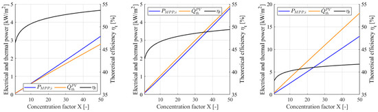
Figure 9.
Key parameters of Spectral Splitting depending on concentration factor for c-Si (left), CIGS (middle) and CdTe (right) PV technology.
6. Discussion and Conclusions
The literature-based results [28,29] and modelling results for spectral and theoretical efficiencies at full spectrum coincide within ±0.2 percentage points (pp) for c-Si, ±2 pp for CIGS and ±1.3 pp for CdTe. These deviations appear to be acceptable for applying the modelling approach also for the Spectral Splitting configurations.
The modelled gains in conversion efficiency demonstrate the potential of the considered Spectral Splitting approach. Especially the results of the spectral efficiency exhibit this effect distinctly, as it only depends on the impinging solar spectrum and the PV technology. Comparing of 48.2% (for c-Si) at full spectrum with of 84.4% in the optimised Spectral Splitting configuration exposes the spectral mismatch the conventional PV operation has to cope with.
The theoretical efficiency can be increased by 64% (c-Si), 58.3% (CIGS) or 29.7% (CdTe), compared to the conventional full spectrum operation. This maximisation corresponds to a significant reduction in the waste heat dissipation within the cells by −91% (c-Si), −84.9% (CIGS) resp. −45.8% (CdTe), which is an important factor for keeping the cell temperature low, especially for the case of applying this concept in mid-temperature CPVT collectors. The electrical output of the considered optimised Spectral Splitting configuration using c-Si or CIGS cells is also lowered considerably (−80.3% resp. −69.4%) compared to the full spectrum operation. In contrast, CdTe cells show a moderate reduction in the electrical output by −19.8%. However, this loss of electrical power can be over-compensated by the additional gain of thermal power output in the proposed CPVT receiver concept, as indicated by the calculated idealised key parameter . Moreover, the filter configuration of maximum efficiency does not necessarily mean to be the optimum arrangement for all operating conditions. The analysis results illustrated in Figure 5, Figure 6 and Figure 7 rather provide the possibility to adapt the Spectral Splitting characteristic to the requirement of the particular application. If the focus lies on the thermal output, and maximum output temperature is demanded, the waste heat dissipation within the PV cells must be kept as low as possible in order to avoid an additional temperature rise of the cells, and therefore the point of maximum can be chosen. By contrast, if more electrical output is required, an absorption filter with a lower can be implemented, but also resulting in more heat dissipation and temperature rise within the cells. Therefore, the thermal output temperature of the receiver has to be limited so that the heat transfer between the thermal and the electrical receiver part does not lead to an overheating of the cells.
Modelling of CdTe cells revealed that the conversion efficiency becomes zero for > 900 nm, which is caused by the specific spectral response of the cells. This implies that the impinging irradiance in the range of 900 nm to 1100 nm is completely dissipated as heat within the cells. Therefore, there would be even more potential for improving the conversion efficiency of CdTe, if the upper threshold wavelength could also be changed from 1100 nm to 900 nm. However, this is not possible in the current concept, as is defined by the HTF.
Comparing the impact of cell temperature on the conversion efficiencies depicts that of the three PV technologies is within a narrow range from 28.9% (CdTe) to 32.9% (CIGS) at a cell temperature of 100 °C. Moreover, c-Si generates an electrical power output of only 36.9 Wel/m², and CdTe shows internal waste heat dissipation with a factor of 3.4 higher than CIGS cells. This allows the conclusion that c-Si would be more suitable for applications with a focus on the thermal output, whereas CdTe could better satisfy higher electrical power demand. CIGS can be seen as a compromise, revealing the best conversion efficiency at 100 °C. A similar summary can also be stated for the impact of the concentration factor on the conversion efficiency. C-Si cells have the best efficiency but the lowest electrical power output. CdTe provides four times higher electrical power output than c-Si at 30 suns, but also the waste heat dissipation is higher by a factor of 6.4. In contrast, CIGS cells can provide a better balance between electrical and thermal output, also under concentration.
The novel CPVT receiver design presented in this paper reveals a realistic and feasible way of implementing the considered Spectral Splitting concept using semiconductor-doped glass and heat transfer fluid as filter elements. The materials utilised in the receiver design and in the given dimensions are available on the market so that the realisation as a prototype is viable. The transmittance characteristics of the solid filter are not continuously adjustable in practice, but the lower threshold wavelength can be chosen in steps of 15 nm to 30 nm within the range from 400 nm to 900 nm. Therefore, an implementation of the optimised filter and the described customisation of the ratio between electrical and thermal output is possible with a certain tolerance.
7. Outlook
Although the presented results are satisfying, further work will be necessary. On the one hand, the electrical model has to be enhanced by including loss mechanisms (reflection, recombination, ohmic) in order to calculate the real efficiency and the real MPP. On the other hand, detailed thermal modelling will be performed so that the real thermal power output, the expected output temperature and the expected PV cell temperature can be determined. With this information, it will be possible to derive exactly the optimum Spectral Splitting filter configuration for each particular application. Moreover, the comparison of thermal and electrical output will be extended to an exergetic consideration for gaining a thorough thermodynamic view on this concept.
Further efficiency increase in CdTe cells could be achieved if the upper threshold wavelength can be modified. Therefore, combining the solid absorption filter with an additional liquid filter for CdTe cells will also be analysed in future work.
Author Contributions
Conceptualisation, A.R. and R.H.; Methodology, A.R. and R.H.; Formal Analysis, A.R.; Software, A.R.; Visualisation, A.R.; Validation, R.H.; Writing—Original Draft Preparation, A.R.; Writing—Review and Editing, R.H.; Project Administration, A.R.; Funding Acquisition, A.R.; Supervision, R.H. All authors have read and agreed to the published version of the manuscript.
Funding
This project is financed by research funds from the government of Upper Austria.
Institutional Review Board Statement
Not applicable.
Informed Consent Statement
Not applicable.
Data Availability Statement
Not applicable.
Acknowledgments
Open Access Funding by the University for Continuing Education Krems, the University of Applied Sciences BFI Vienna and the University of Applied Sciences Upper Austria.
Conflicts of Interest
The authors declare no conflict of interest.
References
- HeatRoadmapEurope. Heating and Cooling—Facts and Figures 2017. Available online: www.heatroadmap.eu (accessed on 11 January 2021).
- Weiss, W.; Spörk-Dür, M. Solar Heat Worldwide—Global Market Development and Trends in 2020|Detailed Market Figures 2019; Gleisdorf, Austria, 2021. [Google Scholar]
- Kaltschmitt, M.; Streicher, W.; Wiese, A. Erneuerbare Energien|Systemtechnik, Wirtschaftlichkeit, Umweltaspekte; Springer: Berlin/Heidelberg, Germany, 2013; Volume 5. [Google Scholar]
- Quaschning, V. Regenerative Energiesysteme|Technologie—Berechnung—Simulation, 7th ed.; Hanser Verlag: Munich, Germany, 2011. [Google Scholar]
- Crisostomo, F.; Taylor, R.A.; Surjadi, D.; Mojiri, A.; Rosengarten, G.; Hawkes, E.R. Spectral splitting strategy and optical model for the development of a concentrating hybrid PV/T collector. Appl. Energy 2015, 141, 238–246. [Google Scholar] [CrossRef]
- Stanley, C.; Mojiri, A.; Karwa, N.; Rosengarten, G. Thermal Performance Analysis of a Concentrating Beam Splitting Hybrid PVT Collector. In Proceedings of the EuroSun 2014 Conference, Aix-les-Bains, France, 16–19 September 2014; International Solar Energy Society: Freiburg im Breisgau, Germany, 2015. [Google Scholar] [CrossRef]
- Imenes, A.G.; Mills, D.R. Spectral beam splitting technology for increased conversion efficiency in solar concentrating systems: A review. Sol. Energy Mater. Sol.Cells 2004, 84, 19–69. [Google Scholar] [CrossRef]
- Green, M.A. General temperature dependence of solar cell performance and implications for device modelling. Prog. Photovolt. Res. Appl. 2003, 11, 333–340. [Google Scholar] [CrossRef]
- Mojiri, A.; Taylor, R.; Thomsen, E.; Rosengarten, G. Spectral beam splitting for efficient conversion of solar energy—A review. Renew. Sustain. Energy Rev. 2013, 28, 654–663. [Google Scholar] [CrossRef]
- Daneshazarian, R.; Cuce, E.; Cuce, P.M.; Sher, F. Concentrating photovoltaic thermal (CPVT) collectors and systems: Theory, performance assessment and applications. Renew. Sustain. Energy Rev. 2018, 81, 473–492. [Google Scholar] [CrossRef]
- George, M.; Pandey, A.K.; Abd Rahim, N.; Tyagi, V.V.; Shahabuddin, S.; Saidur, R. Concentrated photovoltaic thermal systems: A component-by-component view on the developments in the design, heat transfer medium and applications. Energy Convers. Manag. 2019, 186, 15–41. [Google Scholar] [CrossRef] [Green Version]
- Crisostomo, F.; Hjerrild, N.; Mesgari, S.; Li, Q.; Taylor, R.A. A hybrid PV/T collector using spectrally selective absorbing nanofluids. Appl. Energy 2017, 193, 1–14. [Google Scholar] [CrossRef]
- Han, X.; Chen, X.; Sun, Y.; Qu, J. Performance improvement of a PV/T system utilizing Ag/CoSO4-propylene glycol nanofluid optical filter. Energy 2020, 192, 116611. [Google Scholar] [CrossRef]
- Otanicar, T.; Dale, J.; Orosz, M.; Brekke, N.; DeJarnette, D.; Tunkara, E.; Roberts, K.; Harikumar, P. Experimental evaluation of a prototype hybrid CPV/T system utilizing a nanoparticle fluid absorber at elevated temperatures. Appl. Energy 2018, 228, 1531–1539. [Google Scholar] [CrossRef]
- Huaxu, L.; Fuqiang, W.; Dong, Z.; Ziming, C.; Chuanxin, Z.; Bo, L.; Huijin, X. Experimental investigation of cost-effective ZnO nanofluid based spectral splitting CPV/T system. Energy 2020, 194, 116913. [Google Scholar] [CrossRef]
- Huang, G.; Wang, K.; Curt, S.R.; Franchetti, B.; Pesmazoglou, I.; Markides, C.N. On the performance of concentrating fluid-based spectral-splitting hybrid PV-thermal (PV-T) solar collectors. Renew. Energy 2021, 174, 590–605. [Google Scholar] [CrossRef]
- Looser, R.; Vivar, M.; Everett, V. Spectral characterisation and long-term performance analysis of various commercial Heat Transfer Fluids (HTF) as Direct-Absorption Filters for CPV-T beam-splitting applications. Appl. Energy 2014, 113, 1496–1511. [Google Scholar] [CrossRef]
- Everett, V.; Wu, Y.; Resch, A.; Ebert, M.; Vivar, M.; Thomsen, E.; Harvey, J.; Scott, P.; Greaves, M.; Tanner, A.; et al. Towards an innovative spectral-splitting hybrid PV-T micro-concentrator. AIP Conf. Proc. 2012, 1477, 230. [Google Scholar] [CrossRef] [Green Version]
- Stanley, C.; Mojiri, A.; Rahat, M.; Blakers, A.; Rosengarten, G. Performance testing of a spectral beam splitting hybrid PVT solar receiver for linear concentrators. Appl. Energy 2016, 168, 303–313. [Google Scholar] [CrossRef]
- Mojiri, A.; Stanley, C.; Rodriguez-Sanchez, D.; Everett, V.; Blakers, A.; Rosengarten, G. A spectral-splitting PV-thermal volumetric solar receiver. Appl. Energy 2016, 169, 63–71. [Google Scholar] [CrossRef]
- Hangweirer, M.; Höller, R.; Schneider, H. Design and analysis of a novel concentrated photovoltaic–thermal receiver concept. Jpn. J. Appl. Phys. 2015, 54, 08KE01. [Google Scholar] [CrossRef]
- Hangweirer, M. Design und Analyse eines CPV-T Receiver Konzepts; University of Applied Sciences Upper Austria: Wels, Austria, 2014. [Google Scholar]
- Reinbrech, R.; Höller, R.; Schneider, H. Integration of Spectral Splitting in a CPV-T Receiver Concept. In Proceedings of the EU PVSEC 2016, Munich, Germany, 20–24 June 2016. [Google Scholar]
- Resch, A. Implementation of Spectral Splitting in a Hybrid Concentrator Photovoltaic and Thermal Solar Collector; University of Applied Sciences Upper Austria: Wels, Austria, 2012. [Google Scholar]
- Han, X.; Tu, L.; Sun, Y. A spectrally splitting concentrating PV/T system using combined absorption optical filter and linear Fresnel reflector concentrator. Sol. Energy 2021, 223, 168–181. [Google Scholar] [CrossRef]
- Widyolar, B.; Jiang, L.; Winston, R. Spectral beam splitting in hybrid PV/T parabolic trough systems for power generation. Appl. Energy 2018, 209, 236–250. [Google Scholar] [CrossRef]
- Wang, K.; Pantaleo, A.; Herrando, M.; Faccia, M.; Pesmazoglou, I.; Franchetti, B.M.; Markides, C. Spectral-splitting hybrid PV-thermal (PVT) systems for combined heat and power provision to dairy farms. Renew. Energy 2020, 159, 1047–1065. [Google Scholar] [CrossRef]
- Mertens, K. Photovoltaik—Lehrbuch zu Grundlagen, Technologie und Praxis, 4th ed.; Hanser Verlag: München, Germany, 2018. [Google Scholar]
- Häberlin, H. Photovoltaics—System Design and Practice; John Wiley & Sons, Ltd.: Chichester, UK, 2012. [Google Scholar]
- Luque, A.; Hegedus, S. Handbook of Photovoltaic Science and Engineering. 2; John Wiley & Sons, Ltd.: Chichester, UK, 2011. [Google Scholar]
- Resch, A.; Höller, R. Design Concepts for a Spectral Splitting CPVT Receiver. In EuroSun2020 Conference; Charalambides, A., Streicher, W., Mugnier, D., Eds.; ISES: Freiburg im Breisgau, Germany, 2020; p. 12. [Google Scholar] [CrossRef]
- NREL Reference Air Mass 1.5 Spectra n.d. Available online: https://www.nrel.gov/grid/solar-resource/spectra-am1.5.html (accessed on 6 November 2019).
- Green, M.A.; Hishikawa, Y.; Dunlop, E.D.; Levi, D.H.; Hohl-Ebinger, J.; Ho-Baillie, A.W.Y. Solar cell efficiency tables (version 52). Prog. Photovolt. Res. Appl. 2018, 26, 427–436. [Google Scholar] [CrossRef]
- Wu, J.-L.; Hirai, Y.; Kato, T.; Sugimoto, H.; Bermudez, V. New World Record Efficiency up to 22.9% for Cu(In,Ga)(Se,S)2 Thin-Film Solar Cells. In Proceedings of the 7th World Conference on Photovoltaic Energy Conversion, Waikoloa, HI, USA, 10–15 June 2018; p. 4. [Google Scholar]
- Solar Frontier. Datasheet PowerModul n.d. Available online: https://www.solar-frontier.eu/fileadmin/content/downloads/powermodule/20150609/SF-PowerModule_Datenblatt_DE.pdf (accessed on 16 November 2020).
- Green, M.A.; Emery, K.; Hishikawa, Y.; Warta, W.; Dunlop, E.D. Solar cell efficiency tables (Version 45). Prog. Photovolt. Res. Appl. 2015, 23, 659–676. [Google Scholar] [CrossRef]
- First Solar. Datasheet First Solar Series 6 n.d. Available online: http://www.firstsolar.com/-/media/First-Solar/Technical-Documents/Series-6-Datasheets/Series-6-Datasheet.ashx?la=en-Emea (accessed on 16 November 2020).
Publisher’s Note: MDPI stays neutral with regard to jurisdictional claims in published maps and institutional affiliations. |
© 2021 by the authors. Licensee MDPI, Basel, Switzerland. This article is an open access article distributed under the terms and conditions of the Creative Commons Attribution (CC BY) license (https://creativecommons.org/licenses/by/4.0/).